

Page 1
DoorKing Part Number
WIRELESS TRACKER EXPANSION BOARD RF KIT
1489-080
This wireless kit provides wireless communication for a 2358-010 tracker expansion board to a wireless baseboard in a access
control system. Use wireless tracker expansion boards ONLY with DoorKing: 1833, 1835, 1837 and 1838 multi-door access
controller access control systems. DO NOT use with 1838 Access Plus model.
Installation
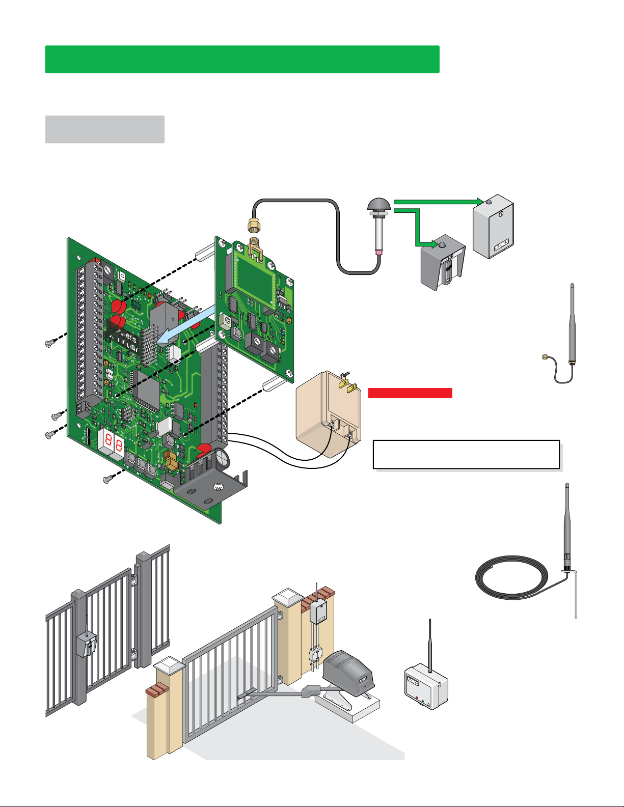
Plug the 1489-010 board into the wireless connector and secure boards with 4 screws to the tracker expansion board. See the HARDwired tracker
expansion board manual to connect desired options to terminals #1- #34 to manage a remote access point. DO NOT CONNECT ANY WIRES TO
TERMINALS #10, #17, #27, #28 or #29 (Used for HARDwire communication line ONLY). Power transformer must connect to tracker expansion
board #33 and #34 (REQUIRED). Antenna is REQUIRED, see below for antenna options.
2358-010 Tracker
1489-010
Expansion Board
BOARD ADDRESS
ON
1
3
4
2
5
1
6
0
RF
7
F
SECURE
8
E
9
0
1
2
3
4
5
6
7
8
9
10
11
12
13
14
15
16
17
18
19
20
4 Screws to secure 1489 board
D
A
C
B
RF
DATA
Wireless
Connector
RF
STAT
CODE
US
SENT
CODE
GOOD
CODE
OUTPUT
BAD
RELA
Y
ALARM
RELA
NC
Y
NO
RESET
AU
X
NC
RELAY
NO
NC
NO
2358-010
RF RANGE
21
22
23
24
25
26
27
28
29
30
31
32
33
34
PR
OGRAM
1489-010
RF ID RF CH
3
4
2
5
1
6
0
7
F
8
E
9
D
3
A
4
C
2
B
5
1
6
0
7
F
8
E
9
D
A
C
B
Transformer
Power
See back page.
to tracker expansion board.
E
N
T
Typical Remote Access Point Installations
IMPORTANT: Install the enclosure
so the antenna is in a location
that is NOT surrounded by metal
and is in free air as high as
possible above the ground.
Cabinet Mounted
Dome Antenna Included
(Vandal-resistant) The range is
approximately 100 ft direct-line-of-sight.
Install on top of a desired cabinet in an
RF
SYNC
existing antenna mounting hole.
RF
LOST
RF
STRENGTH
POWER
Input:
120 V 60 Hz
Output:
16.5 VAC 20
Important Antenna Note: Antenna range WILL VARY GREATLY
depending on individual setup (Antenna height above the
ground, background signal interference, physical obstructions
VA
(trees, buildings etc.) and what antenna you choose). Adverse
weather (rain) CAN also affect antenna range.
Range testing is HIGHLY recommended
Single Board Enclosure
with Built-In Card Reader
Sold separately P/N 1815-231
Cabinet Mounted
Longer Range
Fixed Antenna Included
Range is approximately 200 ft
direct-line-of-sight.
Install on top of a desired
cabinet. NOT vandal-resistant.
before FINAL installation.
Other
Antenna
Options
Externally Mounted
Longer Range
Antenna Kit
Sold separately,
P/N 1514-075
13 ft of cable
Range is approximately 500 ft
direct-line-of-sight. Install antenna
vertically as high as possible in free
air above Tracker Expansion Board.
Single Board
Enclosure
Sold separately
P/N 2351-080
Adjustable
sure
o
rd Encl
trolling
Single Boa
with Built-In Card Reader
Mounted on a Post Con
a Pedestrian Gate/Door
nted
u
gle Board
n
ontrolling a
Si
C
Enclosure Mo
on a Wall
Vehicular Gate Operator
Wireless Repeater
Sold separately, P/N 2364-080
May be necessary to increase the
wireless communication range
between the access control system
and the tracker expansion board(s). It
is located between the wireless antennas. It will
receive a signal sent to it by one wireless system and
repeat that signal to the next wireless system. The
range is approximately 500 ft direct-line-of-sight
with no signal interference or physical obstructions.
Page 2
Board Reference
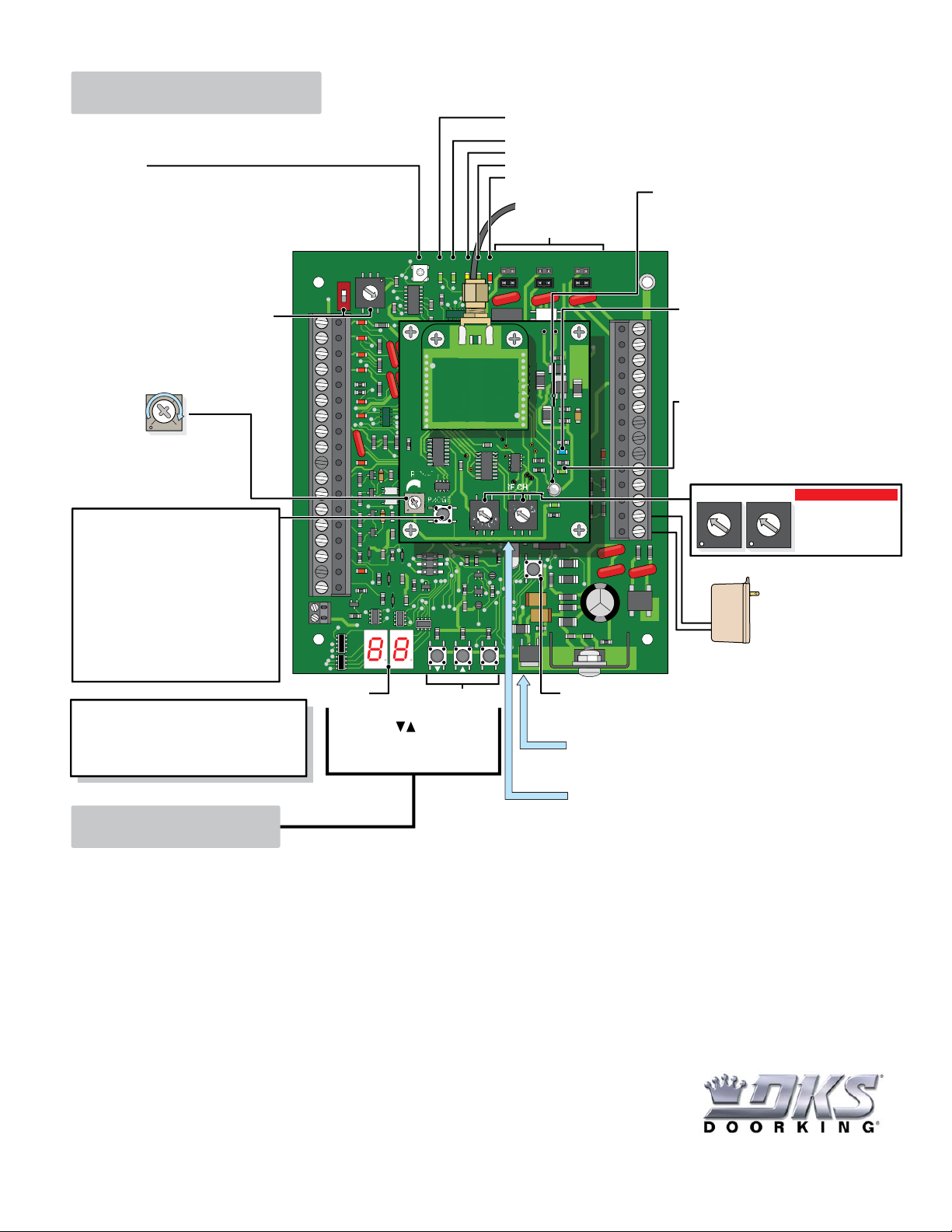
See “Wireless System Layout and Start-Up Procedure”
for system layout limitations.
RF SECURE LED
UNPAIRED MODE:
Steady Red – Board is communicating with unpaired wireless baseboard.
Blinking Red – Board is NOT communicating with unpaired wireless baseboard.
PAIRED MODE:
Steady Green - Board is communicating with paired wireless baseboard.
Blinking Green - Board is NOT communicating with paired wireless baseboard.
BOARD ADDRESS
ON
8
7
9
1
6
0
5
1
4
2
3
Connection to Wiegand 2: Addresses 03-10
Board Address (REQUIRED)
Connection to Wiegand 1: Addresses 11-18
See HARDwire tracker expansion
board manual for more information.
RF Range
Adjustment
Set to max (full clockwise) for
most applications. This may
need to be dialed back to limit
the range when using a repeater.
Program Button:
Press after adjustment has been made to
•
the RF RANGE, RF ID or RF CH before
changes will take effect.
•
Press and hold for 3 sec. to PAIR to
wireless baseboard, may take up to 20
seconds to PAIR.
(RF SECURE LED Paired - steady GREEN).
Press and hold again for 3 sec. to UNPAIR
•
from wireless baseboard if necessary
(RF SECURE LED Unpaired - steady RED).
IMPORTANT Wiring and LED Note:
See HARDwire tracker expansion board manual for
terminal #1 - #34 connections and LED descriptions.
DO NOT connect any wires to terminals #10, #17,
#27, #28 and #29.
1
2
3
4
5
6
7
8
9
10
11
12
13
14
15
16
17
18
19
20
LED Display
0
RF RANGE
Press buttons or
ENT button to activate
LED display.
RF
SECURE
RF
DATA
PROGRAM
1489-010
Programming
RF
CODE
STATUS
SENT
Buttons
RF Data LED – Blinks when receiving a reply from
wireless baseboard after a card code is sent.
RF Status LED – Not used.
Code Sent LED – Blinks after a card code has been sent to wireless baseboard.
Code Good LED – Blinks if the card code is in the database (access granted).
Code Bad LED – Blinks if the card code is not in the database (access denied).
RF Strength LED:
Antenna is REQUIRED.
Board Relay Jumpers
OUTPUT
CODE
CODE
RELAY
GOOD
BAD
NC
NO
ALARM
RELAY
AUX
RELAY
NC
NC
NO
NO
Updated every time a RF SYNC signal is received.
Green - Strong signal - Normal
Yellow - Marginal signal - May lose communication.
Red - Poor signal - Unreliable
2358-010
RF SYNC LED:
Blinking Blue - Connected with wireless baseboard.
Blinking Rapidly - Pairing with wireless baseboard.
21
OFF - No signal with wireless baseboard.
Note: If LED lights for a couple of seconds after the
22
reset button or program button is pressed, this indicates
23
this board has been programmed to forward card codes
for other boards (See program table).
24
25
RF LOST LED:
26
ON - Lost communication with wireless baseboard.
27
OFF - Communication is established with wireless
28
baseboard.
Blinking Rapidly - Pairing with wireless baseboard.
29
30
31
32
33
34
1
0
RF CHRF ID
4
5
3
6
2
F
E
2
7
1
8
0
9
F
A
B
D
C
RF ID RF CH
4
5
3
6
2
7
1
1
8
0
0
9
F
F
A
E
B
D
C
RF
SYNC
RF
LOST
RF
STRENGTH
4
5
3
6
2
E
POWER
7
8
9
A
B
D
C
Power Transformer
RESET
18 GA. Wire 100 ft max
ENT
16 GA. Wire 200 ft max
16.5 VAC
20 VA
RESET Button - Press to reboot tracker expansion board
AND the 1489 wireless board.
2358 Tracker Expansion Board
DoorKing Part Number
1489-080
Important
MUST be set to SAME
4
5
3
6
7
8
ID number and channel
9
A
number as the wireless
E
B
D
C
baseboard.
Power transformer is
REQUIRED and is wired to
terminals #33 and #34, wire
polarity does not matter.
1489 Wireless Board
Programming
See the “HARDwired Installation/Owner’s manual” for complete programming information for the tracker expansion board.
Important Notice
totally lost. Although significant delays or losses of data are rare when wireless devices are used in a normal manner with a well-constructed network, DoorKing wireless products should not
be used in situations where failure to transmit or receive data could result in damage of any kind to the user or any other party, including but not limited to personal injury, death, or loss of
property. DoorKing, Inc. accepts no responsibility for damages of any kind resulting from delays or errors in data transmitted or received using DoorKing wireless products, or for failure of
DoorKing wireless products to transmit or receive such data.
Safety and Hazards
where cellular radio can interfere such as explosive atmospheres, medical equipment, or any other equipment which may be susceptible to any form of radio interference. DoorKing wireless
products can transmit signals that could interfere with this equipment. Do not operate DoorKing wireless products in any aircraft, whether the aircraft is on the ground or in flight. In aircraft,
DoorKing wireless products MUST BE POWERED OFF. When operating, DoorKing wireless products can transmit signals that could interfere with various onboard systems.
Note: Some airlines may permit the use of cellular phones while the aircraft is on the ground and the door is open. DoorKing wireless
products may be used at this time.
The driver or operator of any vehicle should not operate DoorKing wireless products while in control of a moving vehicle. Doing so will detract
from the driver or operator’s control and operation of that vehicle. In some states and provinces, operating such communications devices
while in control of a vehicle is an offence.
1489-065-D-10-14 - Not for Release
Due to the nature of wireless communications, transmission and reception of data can never be guaranteed. Data may be delayed, corrupted (i.e., have errors) or be
Do not operate DoorKing wireless products in areas where cellular modems are not advised without proper device certifications. These areas include environments
120 S. Glasgow Avenue
Copyright 2014 DoorKing, Inc. All rights reserved.
Inglewood, California 90301
U.S.A.
 Loading...