

Page 1
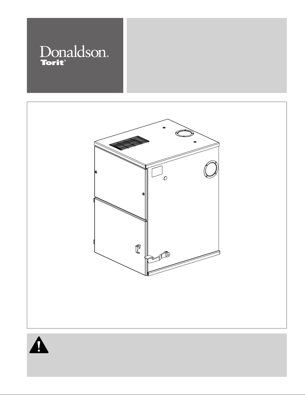
Cabinet Collector
Series 50-90
Models 54, 64, 66, 75, 81, 84, 90
Installation and Operation Manual
Installation, Operation, and Service Information
Models 54-84 Shown
This manual is property of the owner. Leave with the collector when set-up and start-up are complete. Donaldson Company reserves the
right to change design and specifications without prior notice.
Illustrations are for reference only as actual product may vary.
This is the safety alert symbol. It is used to alert you to potential personal injury hazards.
Obey all safety messages that follow this symbol to avoid possible injury or death.
English
Master Language
IOM 7509401 (ENG)
Revision 6
Page 2

Donaldson Company, Inc.
Process owners/operators have important responsibilities relating to combustible hazards.
Process owners/operators must determine whether their process creates combustible
dust, fume, or mist. If combustible dust, fume, or mist is generated, process owners/operators should at a
minimum:
• Comply with all applicable codes and standards. Among other considerations, current NFPA standards
require owners/operators whose processes involve potentially combustible materials to have a current
Hazard Analysis, which can serve as the foundation for their process hazard mitigation strategies.
• Prevent all ignition sources from entering any dust collection equipment.
• Design, select, and implement fire and explosion mitigation, suppression, and isolation strategies that
are appropriate for the risks associated with their application.
• Develop and implement maintenance work practices to maintain a safe operating environment, ensuring
that combustible dust, fume, or mist does not accumulate within the plant.
Donaldson recommends process owners/operators consult with experts to insure each of these
responsibilities are met.
As a manufacturer and supplier of Industrial Filtration Products, Donaldson can assist process owners/
operators in the selection of filtration technologies. However, process owners/operators retain all
responsibility for the suitability of fire and explosion hazard mitigation, suppression, and isolation strategies.
Donaldson assumes no responsibility or liability for the suitability of any fire and/or explosion mitigation
strategy, or any items incorporated into a collector as part of an owner/operators hazard mitigation strategy.
Improper operation of a dust control system may contribute to conditions in the work area or facility that
could result in severe personal injury and product or property damage. Check that all collection equipment is
properly selected and sized for the intended use.
DO NOT operate this equipment until you have read and understand the instruction warnings in the
Installation and Operations Manual. For a replacement manual, contact Donaldson Torit.
This manual contains specific precautionary statements relative to worker safety. Read thoroughly and comply
as directed. Discuss the use and application of this equipment with a Donaldson Torit representative. Instruct all
personnel on safe use and maintenance procedures.
Page 3

Contents
Cabinet Collector, Models 54-90
Description ................................................................................1
Purpose and Intended Use ....................................................1
Rating and Specifications ......................................................2
Operation ...................................................................................3
Inspection on Arrival ...............................................................4
Installation Codes and Procedures ......................................4
Installation.................................................................................4
Foundations or Support Framing .......................................4
Collector Location ................................................................5
Site Selection .......................................................................5
Rigging Instructions.................................................................5
Hoisting Information ............................................................5
Typical Installation ...................................................................6
Standard Equipment ................................................................7
Provisional Anchor Bolt Recommendations ....................7
Electrical Wiring ...................................................................7
Preliminary Start-Up Check ...................................................8
Maintenance Information .......................................................9
Operational Checklist ..........................................................9
Filter Removal and Installation ...........................................9
Filter Pack Maintenance .....................................................9
EZ Filter Pack Removal - Models 54-84 ..........................10
EZ Filter Pack Installation - Models 54-84
Filter Removal - Model 90 .................................................12
Filter Installation - Model 90 .............................................14
Dust Disposal ......................................................................16
Optional Equipment................................................................17
Hopper ..................................................................................17
Hopper Access ...................................................................17
5-Gallon Pail Pack ..............................................................19
55-Gallon Drum Pack .........................................................19
Hopper Attachments ..........................................................20
Indoor Exhaust Deflector ..................................................21
Outdoor Exhaust Deflector ...............................................22
Ductwork .............................................................................23
Magnehelic® Gauge .........................................................24
Outrigger Pack ....................................................................25
HEPA Filter ...........................................................................26
Exhaust Silencer .................................................................28
Attenuator ............................................................................29
Chamber Silencer ...............................................................30
Troubleshooting ......................................................................31
Collector Information.............................................................33
Service Notes .........................................................................34
......................10
Magnehelic® is a registered trademark of Dwyer Instruments, Inc.
DANGER indicates a hazardous situation which, if not avoided, will result
in death or serious injury.
WARNING indicates a hazardous situation which, if not avoided, could
result in death or serious injury.
CAUTION, used with the safety alert symbol, indicates a hazardous
situation which, if not avoided, could result in minor or moderate injury.
NOTICE is used to address practices not related to personal injury that
may result in damage to equipment.
i
Page 4

Donaldson Company, Inc.
Description Purpose and Intended Use
Cabinet Series 50 to 90 dust collectors are selfcontained, intermittent-duty collectors with envelopestyle filters. The Cabinet series collectors provide highly
efficient, low maintenance air cleaning. Filters are
cleaned using the standard manual filter shaker.
Designed to increase the versatility of the collector,
standard options include a dust drawer, hopper
package for a 5-gallon pail or 55-gallon drum, indoor
and outdoor exhaust deflectors, HEPA filter packs,
and exhaust silencers. Four filter media choices and
three construction options are among the many options
available to customize the collector to the specific
application.
Cabinet collectors provide excellent efficiency on
nuisance dust generated in industrial operations and are
a good choice for low airflow, light-load applications that
do not require continuous airflow. Typical applications
include grinding, buffing and polishing, abrasive blasting,
batch mixing, and bag dumping. Often, individual Cabinet
collectors are dedicated to one or two machines.
Four filter media selections offer a wide variety of
characteristics: cotton sateen is the standard media
and provides good efficiency in applications up to 180°F;
polyester sateen provides the same efficiency, but has
higher temperature resistance (240° F) and is more
abrasion-resistant; woven polyester provides better
dust release capabilities with lower efficiency; and
polypropylene provides some chemical resistance up to
180° F.
Note: Standard collectors (Models 54-90) are
limited to 150°F because of internal blower
motor.
Combustible materials such as buffing lint, paper, wood, metal dusts, weld fume, or flammable
coolants or solvents represent potential fire and/or explosion hazards. Use special care when
selecting, installing, and operating all dust, fume, or mist collection equipment when such combustible
materials may be present in order to protect workers and property from serious injury or damage due to a
fire and/or explosion.
Consult and comply with all National and Local Codes related to fire and/or explosion properties of
combustible materials when determining the location and operation of all dust, fume, or mist collection
equipment.
Standard Donaldson Torit equipment is not equipped with fire extinguishing or explosion protection systems.
1
Page 5
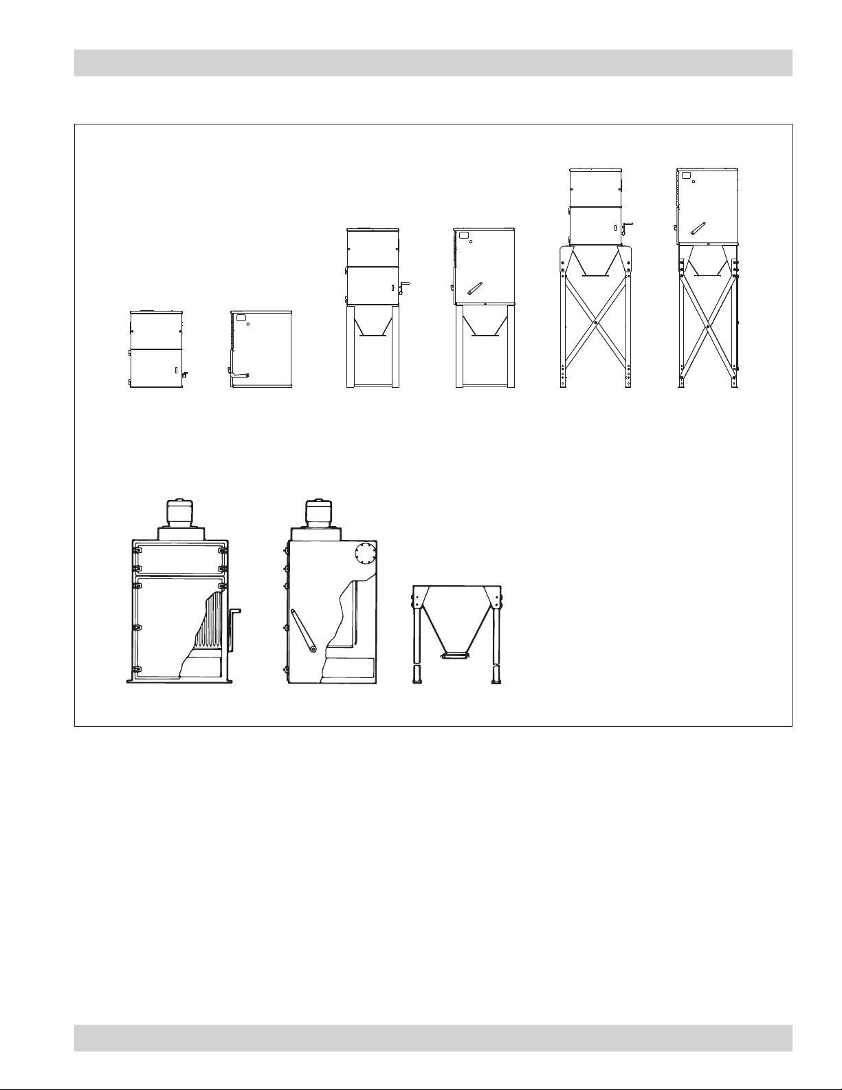
Rating and Specifications
Cabinet Collector, Models 54-90
55-Gallon Drum Pack
Cabinet Models 54-84
5-Gallon Pail Pack
Cabinet Base
Front View Typical
Typical
Side View
Front View
Side View
Cabinet Model 90
FILTER
SECTION
60° SLOPE ON
HOPPER
Front View
Typical
Side View
DUST
DRAWER
Front View
Typical Side View
8” SQUARE
SLIDE GATE
Collectors are rated for the following loads as calculated
per relevant sections of the IBC 2015 code*:
Basic Wind Speed & Exposure
............90 mph, Exposure C
..................................................115 mph, Exposure C (90 only)
Seismic Spectral Acceleration, S
Seismic Spectral Acceleration, S
Installed Collector Base Elevation
Risk Category
.......................................................................... II
................................ .1.5 g
s
................................. 0.6 g
1
...............................Grade
Housing rating, inches water gauge ............................+/- 20
Control power
...............................................120-Volt 50/60 Hz
*If collector was supplied with a Record Drawing,
the specifications on the drawing will supersede the
standard specifications above.
2
Page 6
Donaldson Company, Inc.
Operation
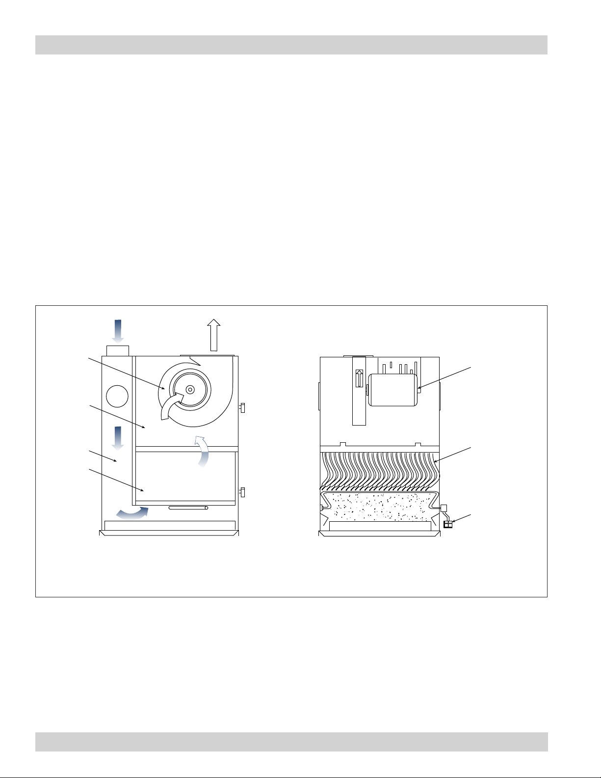
During normal operation, dust-laden air enters the
collector through the dirty-air inlet and passes through
the collector where the dust collects on the outside
surface of the filter media. As dust collects on the filter
surfaces, a dust cake forms, which actually improves the
efficiency of the filters. The greater the amount of dust
cake accumulated, the higher the efficiency of the filter.
dirty-air inlet
blower ON
clean-air
chamber
clean-air outlet
The filtered air flows up through the center of the
filters and into the clean-air chamber. Clean, filtered air
discharges through clean-air outlet located on top of the
collector.
To clean the filters the fan must first be shut off. Pushing
down on the hand- or foot-operated shaker pedal and
releasing rapidly six times completes manual filter
cleaning. The releasing action causes the dust cake to
fracture and fall into the dust storage area.
blower
motor OFF
fan rotation
stopped
inlet zone
filter bags
Normal Operation
Side View
Collector Operation (Cabinet 54-84 Shown)
Filter Cleaning
Front View
filter bags
shaker pedal
press down
and release
quickly six
times
3
Page 7
Cabinet Collector, Models 54-90
Inspection on Arrival
1. Inspect collector upon delivery.
2. Report any damage to the delivery carrier.
3. Request a written inspection report from the Claims
Inspector to substantiate any damage claim.
4. File claims with the delivery carrier.
5. Compare collector received with description of
product ordered.
6. Report incomplete shipments to the delivery carrier
and your Donaldson Torit representative.
7. Remove crates and shipping straps. Remove loose
components and accessory packages before lifting
collector from truck.
8. Check for hardware that may have loosened during
shipping.
9. Use caution removing temporary covers.
Installation Codes and Procedures
Codes may regulate recirculating
filtered air in your facility.
Consult with the appropriate authorities
having jurisdiction to ensure compliance
with all national and local codes regarding
recirculating filtered air.
Safe and efficient operation of the collector depends on
proper installation.
Authorities with jurisdiction should be consulted
before installing to verify local codes and installation
procedures. In the absence of such codes, install
collector according to the National Electric Code,
NFPA No. 70-latest edition and NFPA 91 (NFPA 654 if
combustible dust is present).
Installation
Use proper equipment and adopt
all safety precautions needed for
servicing equipment.
Electrical service or maintenance work must
be performed by a qualified electrician and
comply with all applicable national and local
codes.
Turn power off and lock out electrical
power sources before performing service or
maintenance work.
Do not install in classified hazardous
atmospheres without an enclosure rated for
the application.
Site selection must account for
wind, seismic zone, and other
load conditions when selecting the location for
collectors.
Codes may regulate acceptable locations for
installing dust collectors. Consult with the
appropriate authorities having jurisdiction to
ensure compliance with all national and local
codes regarding mist collector installation.
Collectors must be anchored in a manner
consistent with local code requirements.
Anchors must be sufficient to support dead,
live, seismic, and other anticipated loads.
Consult a qualified engineer for final selection
of anchorage.
The collector is suitable for either indoor or outdoor
installations. Reference the Rating and Specification
Information.
A qualified installation and service agent must complete
installation and service of this equipment.
All shipping materials, including shipping covers, must
be removed from the collector prior to or during collector
installation.
Failure to remove shipping
materials from the collector will
compromise collector performance.
Inspect collector to ensure all hardware is properly
installed and tight prior to operating collector.
4
Foundations or Support Framing
Prepare the foundation or support framing in the
selected location. Foundation or support framing must
comply with local code requirements and may require
engineering.
Foundation and support framing must be capable of
supporting dead, live, wind, seismic and other applicable
loads. Consult a qualified engineer for final selection of
foundation or support framing.
Page 8
Donaldson Company, Inc.
Collector Location
Donaldson Torit equipment is not
designed to support site installed
ducts, interconnecting piping, or electrical
services. All ducts, piping, or electrical
services must be adequately supported to
prevent severe personal injury and/or property
damage.
When hazardous conditions or materials are
present, consult with local authorities for the
proper location of the collector.
Dust collection equipment may
reach peak sound pressure
levels above 80 dB (A). Noise levels should be
considered when selecting collector location.
Locate the collector to ensure easy access to electrical
and compressed air connections, to simplify solids
collection container handling and routine maintenance,
and to ensure the straightest inlet and outlet ducts.
Site Selection
This collector can be located on a foundation or
structural framing.
Provide clearance from heat sources and avoid any
interference with utilities when selecting the location.
Portable collectors require special installation
accommodations.
Rigging Instructions
Suggested Tools & Equipment
Clevis Pins and Clamps Lifting Slings
Crane or Forklift Pipe Sealant
Drift Pins Pipe Wrenches
Drill and Drill Bits Screwdrivers
End Wrenches Socket Wrenches
Adjustable Wrench Spreader Bars
Torque Wrench (inch/lbs, 9/16-in Socket)
Hoisting Information
Failure to lift the collector
correctly can result in severe
personal injury and/or property damage.
Use appropriate lifting equipment and adopt
all safety precautions needed for moving and
handling the equipment.
A crane or forklift is recommended for
unloading, assembly, and installation of the
collector.
Location must be clear of all obstructions, such
as utility lines or roof overhang.
Use all lifting points provided.
Use clevis connectors, not hooks, on lifting slings.
Use spreader bars to prevent damage to collector’s
casing.
Check the Specification Control drawing for weight and
dimensions of the collector and components to ensure
adequate crane capacity.
Allow only qualified crane or forklift operators to lift the
equipment.
Refer to applicable OSHA regulations and local codes
when using cranes, forklifts, and other lifting equipment.
Lift collector and accessories separately and assemble
after collector is in place.
Use drift pins to align holes in section flanges during
assembly.
5
Page 9
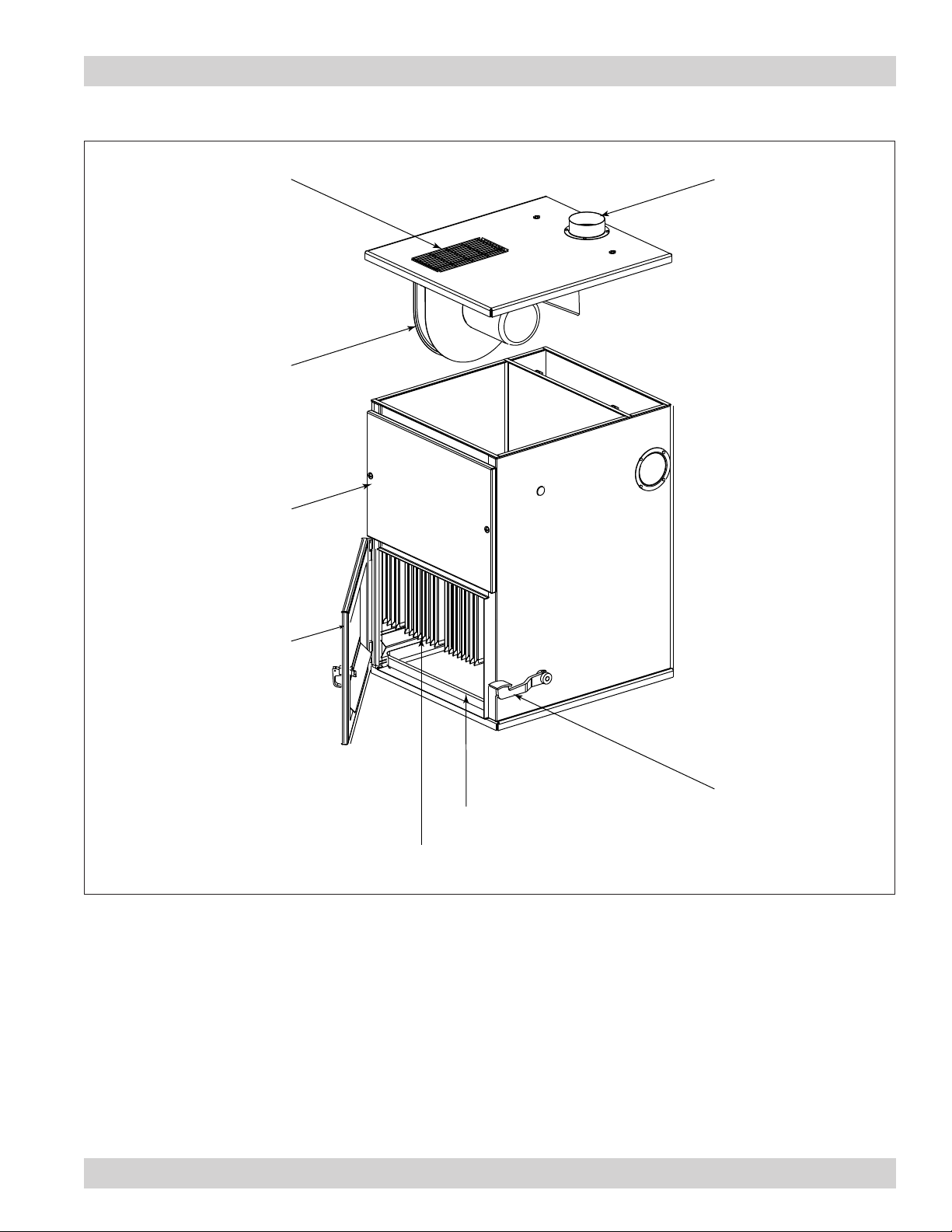
Typical Installation
Cabinet Collector, Models 54-90
clean-air outlet
blower
top door assembly
dirty-air inlet
(one of three
optional locations)
bottom door assembly
shaker pedal
dust drawer
EZ Filter Pack
Typical Installation (Cabinet 54-84 Shown)
6
Page 10
Donaldson Company, Inc.
Standard Equipment
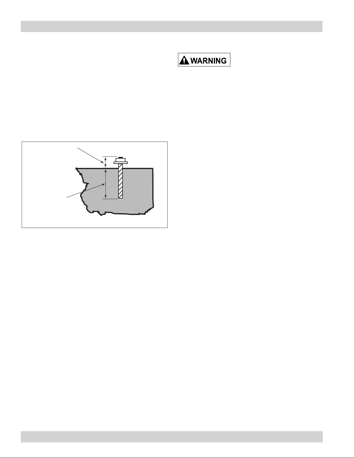
Provisional Anchor Bolt Recommendations
1. Consider Hilti HIT-HY 200 Anchor System or
equivalent. Quantity of anchor bolts should match the
number of holes provided in the base plates.
2. Anchor diameter is typically 1/8-in less than
baseplate hole diameter.
3. Corrosive environment or outdoor installation may
require stainless steel anchors.
Anchor should project
a minimum of 1 3/4-in
and account for nut,
washer, base plate
and shims/grout.
Embedment depth
(suitable for the
physical properties
of the foundation).
Electrical Wiring
Electrical installation, service,
or maintenance work must
be performed by a qualified electrician and
comply with all applicable national and local
codes.
Turn power off and lock out electrical
power sources before performing service or
maintenance work.
Do not install in classified hazardous
atmospheres without an enclosure rated for
the application.
All electrical wiring and connections, including electrical
grounding, should be made in accordance with the
National Electric Code (NFPA No. 70-latest edition).
Check local ordinances for additional requirements that
apply.
The appropriate wiring schematic and electrical rating
must be used. See collector’s rating plate for required
voltage.
Typical Foundation Anchor for Collectors With Hopper
and Leg Assemblies
An electric disconnect switch having adequate amp
capacity shall be installed in accordance with Part IX,
Article 430 of the National Electrical Code (NFPA No.
70-latest edition). Check collector’s rating plate for
voltage and amperage ratings.
Refer to the wiring diagram for the number of wires
required for main power wiring and remote wiring.
7
Page 11

Preliminary Start-Up Check
Cabinet Collector, Models 54-90
Instruct all personnel on safe use and maintenance
procedures.
Electrical work during
installation, service or
maintenance must be performed by a qualified
electrician and comply with all applicable
national and local codes.
Turn power off and lock out electrical
power sources before performing service or
maintenance work.
Check that the collector is clear and free of all
debris before starting.
Do not install in classified hazardous
atmospheres without an enclosure rated for
the application.
1. Check all electrical connections for tightness and
contact.
2. Check for proper rotation as noted on the fan and/or
hopper discharge device housing.
5. Check that fan exhaust damper (if provided) is set to
the fully-closed position.
6. Check and remove all loose items in or near the inlet
and outlet of the collector.
7. Check that all remote controls are properly wired
and all service switches are in the OFF position.
8. Check that all optional accessories are installed
properly and secured.
9. Turn power ON at source.
10. Turn fan motor ON.
11. Adjust airflow with the exhaust damper, if applicable.
Excess airflow can shorten filter
life, cause electrical system
failure and fan motor failure.
12. When airflow diminishes, turn the collector OFF and
manually shake the filter pack.
To reverse rotation, single-phase power supply:
Follow manufacturer’s instructions on the motor’s
nameplate.
To reverse rotation, three-phase power supply:
Switch any two leads on the motor junction box.
Do not look into fan outlet to
determine rotation. View the fan
rotation through the back of the motor.
Check that the exhaust plenum is free of tools
or debris before checking blower/fan rotation.
Stand clear of exhaust to avoid personal injury.
Do not interchange a power lead with the
ground wire. Severe personal injury and/or
property damage may result.
3. All access panels should be sealed and secure.
4. Check that the dust container (if provided) is properly
sealed and clamped.
8
Page 12

Donaldson Company, Inc.
Maintenance Information
Instruct all personnel on safe use and maintenance
procedures.
Use proper equipment and adopt
all safety precautions needed for
servicing equipment.
Use appropriate access equipment and
procedures. Note the standard collector is not
equipped with access platforms unless noted
on the specification drawings.
Electrical service or maintenance work must
be performed by a qualified electrician and
comply with all applicable national and local
codes.
Turn power off and lock out electrical
power sources before performing service or
maintenance work.
Do not install in classified hazardous
atmospheres without an enclosure rated for
the application.
Operational Checklist
1. Monitor the physical condition of the collector and
repair or replace any damaged components.
Routine inspections will minimize downtime and
maintain optimum system performance. This
is particularly important on continuous-duty
applications.
2. Monitor pressure drop across filters.
Abnormal changes in pressure drop may indicate a
change in operating conditions and possibly a fault
to be corrected.
Filter Removal and Installation
Use proper safety and protective
equipment when removing
contaminants and filters.
Dirty filters may be heavier than they appear.
Use care when removing filters to avoid
personal injury and/or property damage.
Turn power off and lock out electrical
power sources before performing service or
maintenance work.
Do not operate with missing or damaged filters.
Filter Pack Maintenance
1. Clean the filters once each day depending on load
circumstances.
2. Shut off fan.
3. Allow fan to coast down.
4. Depress the cleaning pedal or handle.
5. Release to allow cleaning pedal or handle to drop
rapidly.
6. Repeat step 4 six to eight times.
7. Allow dust to settle.
8. Open filter access door and remove any dust which
has now accumulated in the dust drawer.
9. Close the filter access door.
10. A good practice is to clean filters at break, lunch,
and end of day.
3. Monitor exhaust.
4. Monitor dust disposal.
9
Page 13

EZ Filter Pack Removal - Models 54-84
1. Remove upper door and open lower door.
Step 1
2. Loosen the filter pack slide latch wing screws and
move the slide latches away from the gasket by
sliding them inward. Note, this is easier when the
filter pack is supported with one hand on the bottom
side.
Cabinet Collector, Models 54-90
4. Allow the filter pack to collapse in the center and
remove it by guiding it out the bottom side of the
sealing frame.
EZ Filter Pack Installation - Models 54-84
1. Remove banded EZ Filter Pack from box. Do not
remove bands.
2. Fully loosen wing screws.
3. Move slide latches to the rear—away from gasket.
loosen wing
slide to rear
screws
Step 2
3. Remove the center support bar by unscrewing the
wing screws on each end. Note, this is easier when
the filter pack is supported with one hand on the
bottom side.
Steps 1-3
4. Insert banded EZ Filter Pack over shaker bar.
Step 4
Step 3
10
Page 14

Donaldson Company, Inc.
5. Rest banded EZ Filter Pack on shaker bar.
Step 5
6. Cut and remove bands and cardboard protectors.
8. Important - place one hand under center of EZ
Filter Pack. Holding EZ Filter Pack against bottom of
cabinet ledge, push each slide latch over cabinet
ledge.
Do not tighten wing screws at this time.
Step 8
9. Adjust EZ Filter Pack for good fit. Finger tighten wing
screws.
Step 6
7. Insert one hand midway under each side of the
EZ Filter Pack. Push EZ Filter Pack to bottom of
cabinet filter frame.
Step 7
Step 9
10. Remove support bar from box.
Step 10
11
Page 15

Cabinet Collector, Models 54-90
Filter Removal - Model 90
11. Place support bar over center of EZ Filter Pack
Step 11
12. Insert small wing screws through holes in support
bar. Hand tighten all wing screws.
1. Remove upper and lower doors to access the filters.
2. Loosen both set screws on the front and rear hold
down brackets.
Step 1
Step 2
3. Remove front hold down bar.
Step 12
13. Inspect filter seal.
14. Insert clean dust pan.
15. Install and close doors.
Steps 13-15
Step 3
4. Remove rear hold down bar.
Step 4
12
Page 16

Donaldson Company, Inc.
5. Insert rear filter inserter as shown with long arm
towards the front. Insert the right angle plate as
shown BETWEEN two filters. DO NOT insert the
angle bracket inside of a filter. Insert the rear angle
bracket in the space between the filter to the left of
the front angle bracket and the next filter to the left
so both angle brackets are straddling one filter.
Step 5
6. Swing the long arm of the filter inserter from left
to right to open a space around the filter that the
inserter is straddling. Make sure the inserter is
pushed all the way to the back of the bags.
7. Install the front filter inserter with the long arm
towards the back as shown and the angle brackets
inserted into the spaces created by the rear filter
inserter.
Step 7
8. Swing the long arm of the filter inserter from right
to left while keeping the inserter tight to the front of
the bags. This will create a space that will allow the
removal of the first bag.
13
Step 6
Step 8
Page 17

Cabinet Collector, Models 54-90
Filter Installation - Model 90
9. Remove the filter that is between the filter inserts.
Step 9
10. Remove the filter inserters and the rest of the filters.
1. Install the bags into the collector. All but the last bag
should be able to be installed easily.
2. Slide the rear hold down bar beneath the set screws
at the back of the collector.
Steps 1-2
3. To create space to install the last filter, install the
rear filter inserter so the right and left angle brackets
straddle one filter. Position the filter inserter so the
long arm of the inserter is towards the front.
Step 10
Step 3
14
Page 18

Donaldson Company, Inc.
4. Swing the long arm of the filter inserter from left
to right to open a space around the filter that the
inserter is straddling. Make sure the inserter is
pushed all the way to the back of the bags.
Step 4
5. Install the front filter inserter with the long arm
towards the back as shown and the angle brackets
inserted into the spaces created by the rear filter
inserter.
6. Swing the long arm of the filter inserter from right
to left while keeping the inserter tight to the front of
the bags. This will create a space that will allow the
installation of the last bag.
Step 6
7. Insert the final filter in the space created by filter
inserters. When done with the final filter, release the
filter inserters and rest them on top of the bags so
they are easy to locate for future use
15
Step 5
Step 7
Page 19

Cabinet Collector, Models 54-90
8. Install the front hold down bar.
Steps 8
9. Tighten both front and rear hold down bar set
screws.
10. To make sure all bags are sealed properly, shine a
light up between each set of filters. If no light can be
seen from the top side, the bags are properly sealed.
If light can be seen, insert the filter inserter inside
the bag with the bent frame to expand the inside
width of the bag. In addition, it may be necessary to
install a bag clip (refer to the replacement parts list)
at the location of the leak and adjacent bag.
Step 9
Step 10
Dust Disposal
1. Turn collector OFF and empty dust container as
necessary to minimize dust in the hopper.
2. If the optional 5- or 55-gallon drum attachment is
used, empty when drum is 2/3 full.
3. If optional slide gate is used, close gate before
servicing drum.
4. Reinstall drum and open gate.
16
Page 20

Donaldson Company, Inc.
Optional Equipment
Hopper
cabinet
1. Attach legs and cross bracing to hopper using 3/816 x 1-in bolts, washers, and nuts as shown. Cross
braces can be installed to allow front or back hopper
access.
Note: The 5-gallon pail hopper does not require
cross bracing.
2. Position the hopper and leg assembly on the
foundation’s anchor bolts and fasten securely.
3. Apply 1/4-in diameter rope-type sealant to the
hopper’s top flange.
4. Lift cabinet over hopper and leg assembly and lower
slowly.
5. Secure with bolts, washers, and nuts supplied.
Hopper Access
Completely turn off and lock out
all dust collector and ancillary
equipment before accessing the inside of the
hopper.
3/8-in flat washer
3/8-16 x 1-in bolt
see Detail A
leg
hopper
cabinet
sealant
hopper
Dust may build up behind hatch and fall out
when opened. Position yourselft so dust will
not hit you.
Most dusts present safety and health hazards
that require precautions.
Wear eye, respiratory, head and other
protective equipment suitable for the type of
dust.
Detail A
Hopper to 5-Gallon Pail Assembly
(Size 90 hopper is welded to cabinet)
17
Page 21
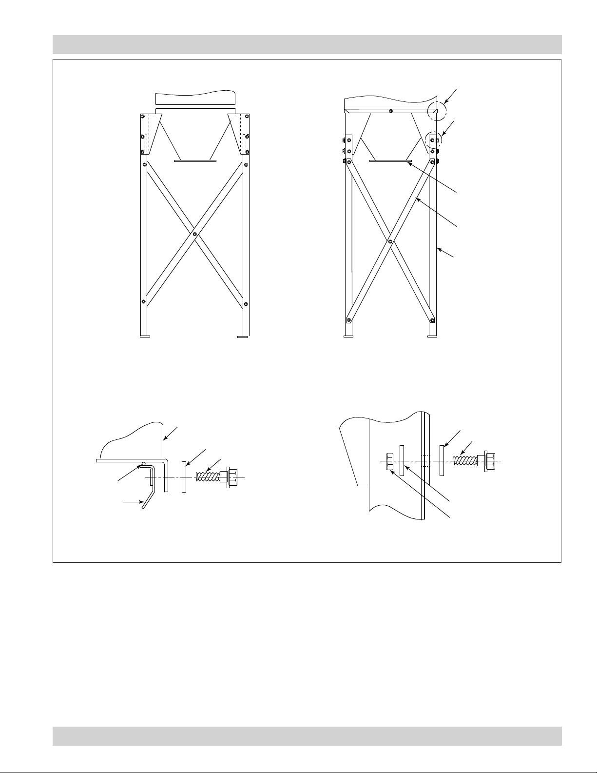
Cabinet Collector, Models 54-90
See Detail A
See Detail B
hopper
cross brace
two, 2 x 50.62-in
leg
sealant
hopper
Front View
cabinet
3/8-in flat washer
Side View
3/8-in flat washer
3/8-16 x 1-in bolt
3/8-16 x 1-in bolt
3/8-in flat washer
3/8-16 hex nut
Detail BDetail A
Hopper to 55-Gallon Drum Assembly
(Size 90 hopper is welded to cabinet)
18
Page 22

Donaldson Company, Inc.
5-Gallon Pail Pack
1. Apply sealant to the hopper flange or the pail cover
mounting plate flange toward the inside edge of the
bolt pattern.
2. Fasten the pail pack to the hopper using the bolts,
washers, and nuts supplied.
3. Place pail beneath seater mechanism.
4. Tighten clamps on either side by pulling down.
55-Gallon Drum Pack
The drum pack is designed to fit a customer-supplied,
standard 55-gallon drum and provides easy access for
dust removal and disposal. A flexible hose connects
the drum cover to the hopper. Placing a pallet under the
drum allows heavier materials to be moved quickly using
a forklift or pallet jack. If a pallet is used, the length of
flexible hose may need to be shortened.
Sharp edge of slide gate may
result in personal injury while
closing the slide gate. Keep hands clear when
operating the slide gate.
With Slide Gate
1. Place the 1/8-in gasket spacer between the hopper
flange and slide gate as shown.
2. Attach the drum pack and slide gate to the hopper
flange using 3/8-16 bolts, washers, and hex nuts.
3. Attach the drum cover to the 55-gallon drum.
4. Use latches to secure the cover to the drum, if
equipped.
5. Connect the flexible hose between the drum cover
and slide gate. Secure with hose clamps.
Without Slide Gate
1. Place 1/4-in diameter rope-type sealant between the
hopper flange and the drum cover mounting flange
toward the inside edge of the bolt pattern.
2. Fasten using the bolts, washers, and nuts supplied.
3. Attach the drum cover to the 55-gallon drum.
4. Use latches to secure the cover to the drum, if
equipped.
5. Connect the flexible hose between the drum cover
and the adapter. Secure with hose clamps.
19
Page 23
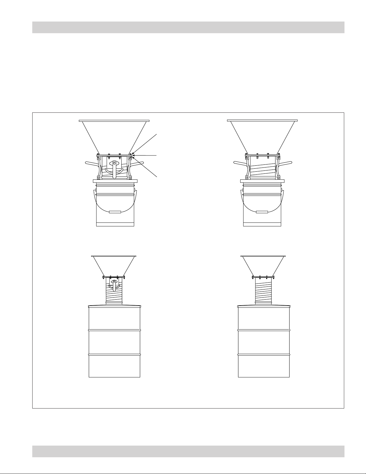
Hopper Attachments
5- or 55-Gallon Drum Packs with or without Slide
Gate
1. Apply 1/4-in diameter rope-type sealant to the drum
cover mounting plate flange.
hopper flange
sealant
drum or pail cover
mounting plate
Cabinet Collector, Models 54-90
2. Fasten the drum cover assembly to the hopper flange
using the hardware supplied.
Pail Pack
with Gate Valve
Models 54-84 Shown
Drum Cover Pack
with Gate Valve
Models 54-84 Shown
Pail Pack
without Gate Valve
Models 54-84 Shown
Drum Cover Pack
without Gate Valve
5- or 55-Gallon Drum Packs with and without Slide Gate
20
Page 24
Donaldson Company, Inc.
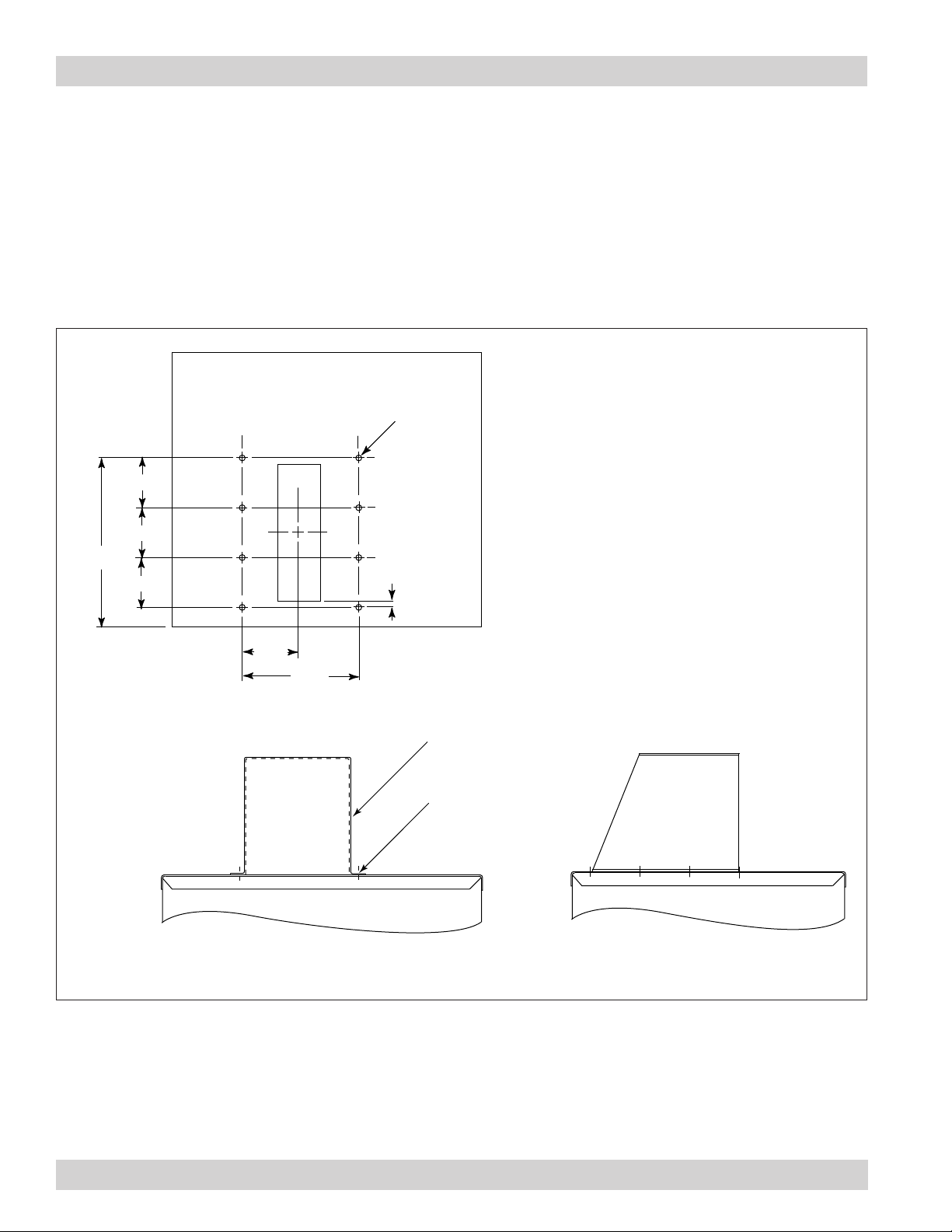
Indoor Exhaust Deflector
1. Remove the top door assembly and set aside.
2. Place a piece of non-combustible cloth over the
filters in the clean-air chamber to protect them from
drilling chips.
3. Use a .213-in diameter drill bit to drill eight holes as
shown.
.213
8x
3.50
3.50
10.50
3.50
.50
4. Position the indoor exhaust deflector on the cabinet
top and fasten using eight 1/4-20 thread-cutting
screws. Tighten securely.
5. Carefully remove the cloth protecting the filters.
Replace the top door assembly and tighten securely
by hand.
4.20
8.41
Drill Location
indoor
exhaust deflector
1/4-20 thread
cutting screw
Front View
Indoor Exhaust Deflector (only available on models 54-84)
Left Side View
21
Page 25
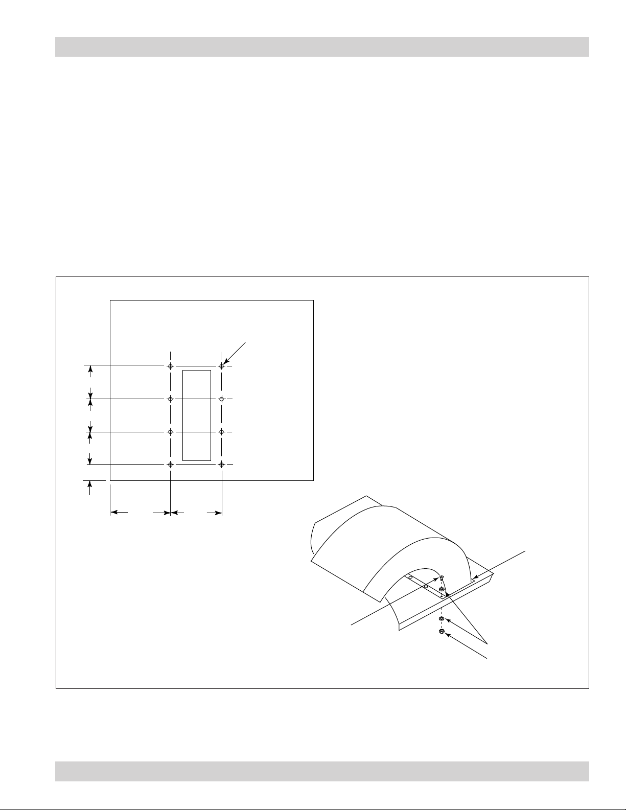
Outdoor Exhaust Deflector
Cabinet Collector, Models 54-90
1. Remove the top door assembly and set aside.
2. Place a piece of non-combustible cloth over the
filters in the clean-air chamber to protect them from
drilling chips.
3. Use a .218-in diameter drill bit to drill eight holes as
shown.
.218
8x
3.25
3.25
4. Position the outdoor exhaust deflector on the cabinet
top, align holes and fasten using eight #10-24 x 1/2-in
bolts, washers, and nuts supplied. Tighten securely.
5. Apply sealant around outside edge of the exhaust
deflector.
6. Carefully remove the cloth protecting the filters.
Replace the top door assembly and tighten securely
by hand.
3.25
2.37
8.94
7.31
sealant
10-24 x 1/2-in
slot-head screw
#10 flat washer
10-24 hex nut
Outdoor Exhaust Deflector (only available on models 54-84)
22
Page 26

Donaldson Company, Inc.
Ductwork
If collector is operated with more
than the maximum permissible
inlet size, the fan motor can overload or dust
can settle in the duct due to low air velocity.
1. Inlet collars can be located on the side, top, or back
of the cabinet by removing the desired inlet cover
plate and installing the inlet collar using the same
screws.
2. Use the shortest possible inlet duct. Avoid the use
of tees or flexible, wire-molded duct except where
machine motion or vibration needs to be isolated.
Flexible duct has a high static pressure and reduces
airflow.
3. Size duct for the recommended air velocity of the
conveyed material or material may collect inside the
duct.
4. Connect joints with sheet metal screws, rivets, or
sealer. Finish each joint with sealer or duct tape.
Note: Sheet metal screws may cause fibrous
or stringing particulate to accumulate
inside duct. Use rivets or sealant in these
conditions.
23
Page 27
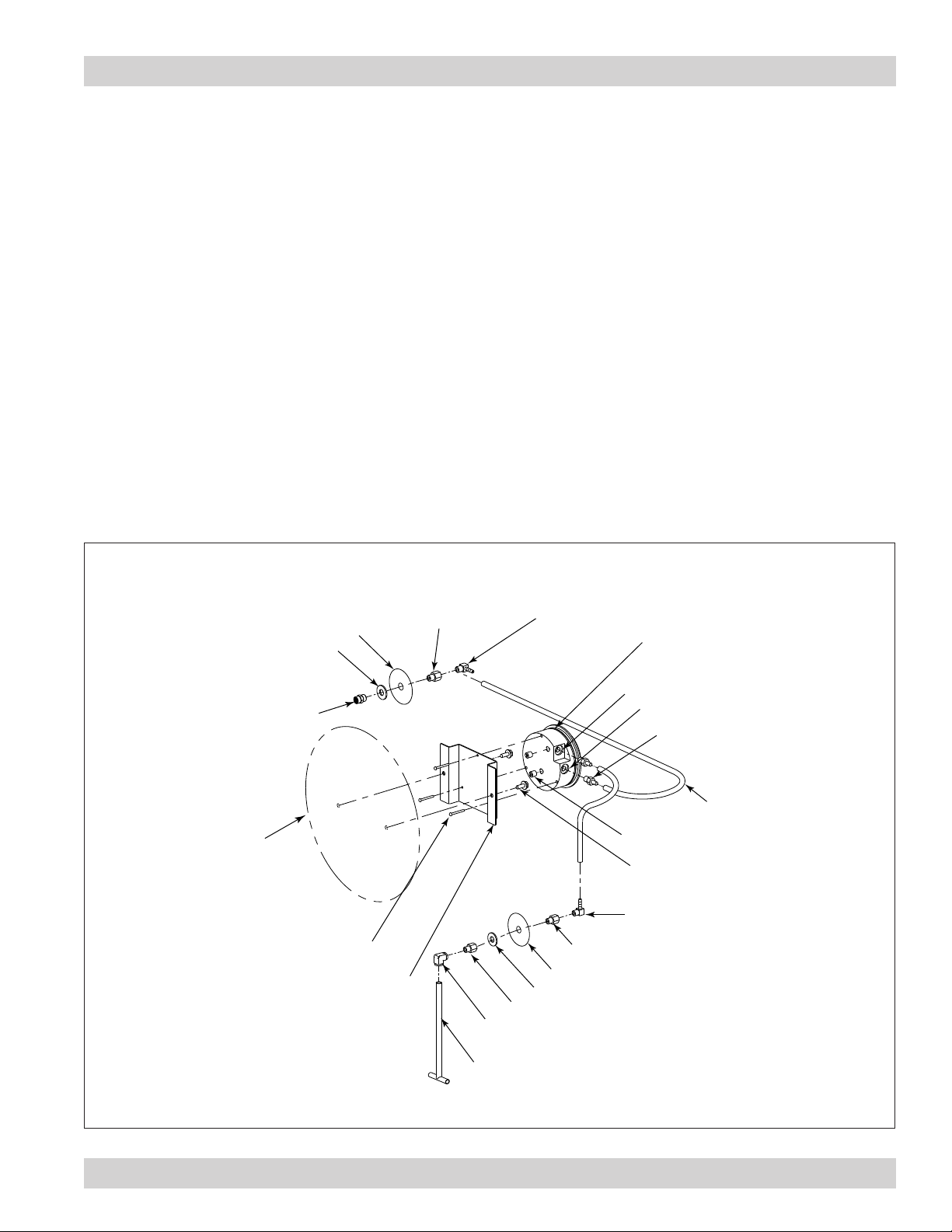
Magnehelic® Gauge
Cabinet Collector, Models 54-90
The Magnehelic is a differential pressure gauge used
to measure the pressure difference between the cleanair and dirty-air plenums and provides a visual display
of filter change requirements. The high-pressure tap is
located in the dirty-air plenum and the low-pressure tap
is located in the clean-air plenum.
1. Choose a convenient, accessible location on or near
the collector for mounting that provides the best
visual advantage.
2. Plug the pressure ports on the back of the gauge
using two, 1/8-in NPT pipe plugs supplied. Install
two, 1/8-in NPT male adapters supplied with the
gauge into the high- and low-pressure ports on the
side of the gauges.
clean-air plenum pressure
tap location
plenum tap location
3/8-in flat washer
1/8-in NPT coupling
1/8-in NPT adapter
3. Attach the mounting bracket using three, #6-32 x 1/4in screws supplied.
4. Mount the gauge and bracket assembly to the
supporting structure using two, self-drilling screws.
5. Thirty-five feet of plastic tubing is supplied and must
be cut in two sections. Connect one section of tubing
from the gauge’s high-pressure port to the pressure
fitting located in the dirty-air plenum. Connect
remaining tubing from the gauge’s low-pressure
port to the fitting in the clean-air plenum. Additional
tubing can be ordered from your representative.
6. Zero and maintain the gauge as directed in the
manufacturer’s Operating and Maintenance
Instructions provided.
1/8-in NPT x 90°
male elbow
Magnehelic gauge
high-pressure port
low-pressure port
two, 1/8-in NPT
adapters
plastic tubing
support structure
mounting surface
#6-32 x 1/4-in mounting screws
mounting bracket
1/8-in NPT adapter
dirty-air plenum pressure tap location
3/8-in flat washer
1/8-in NPT adapter
1/8-in NPT x 90° elbow
static pressure tee
two, 1/8-in NPT pipe plugs
two, self-drilling screws
1/8-in NPT x 90° male elbow
Magnehelic Gauge Assembly
24
Page 28

Donaldson Company, Inc.
Outrigger Pack
Note: Outrigger pack is for use with dust drawer
models only.
Outriggers are standard for Model 90.
1. Center the collector on the outrigger pack aligning
the appropriate bolt patterns.
2. Fasten the four mounting tabs to the outrigger base
using four 5/16-18 x 4-in bolts, washers, and nuts.
Tighten securely.
3. Drill four .312-in diameter holes in the cabinet base
using the mounting tab holes as a guide.
4. Attach the cabinet base to the mounting tabs using
four 5/16-18 x 3/4-in bolts, washers, and nuts. Tighten
securely.
Series 50
Series 60 and 70
Series 80
Center the unit on the outrigger pack
aligning the appropriate bolt patterns.
fasten mounting tabs
to outrigger base using
5/16-18 x 4-in bolts,
flat washers, and hex nuts
mounting tab
outrigger base
match drill .312-in
diameter holes in
cabinet base
fasten cabinet base
to mounting tabs using
5/16-18 x 3/4-in bolts,
flat washers, and hex nuts
25
Outrigger Pack Assembly (casters are optional on models 90-3 and 90-5)
Page 29
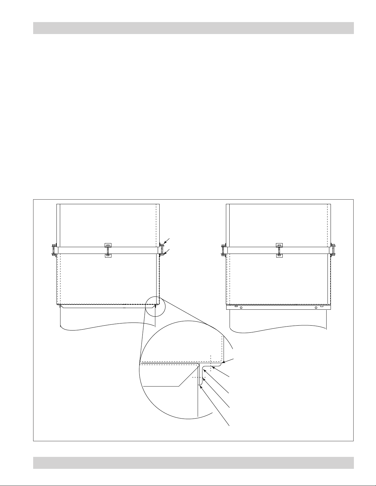
HEPA Filter
Models 60 and 70
Cabinet Collector, Models 54-90
1. Position the HEPA filter pack on top of the collector
as shown.
2. Remove the top door assembly and set aside.
3. Place a piece of non-combustible cloth over the
filters in the clean-air chamber to protect them from
drilling chips.
4. Position angle bracket on each side of the collector
flush with the top and under the HEPA filter brackets
as shown.
5. Using the holes in the angle brackets as a guide, drill
two .213-in diameter holes in the cabinet side and
two in the HEPA filter pack.
5/16-18 lock nut
5/16-18 x 2.5-in
hex bolt
6. Remove HEPA filter pack and apply silicone sealant
around mounting surface.
7. Fasten angle bracket to cabinet using four
1/4-20 thread-cutting screws supplied.
8. Align holes in the HEPA filter pack angle brackets
with the holes drilled in the bracket top surfaces and
secure using four 1/4-20 thread-cutting screws.
9. Carefully remove the cloth protecting the filters.
Replace the top door assembly and tighten securely
by hand.
drill four .213-in diameter
holes per side
1 2 3 4
Front View
HEPA Filter Pack
Cabinet Top
silicone sealant around
all mounting surfaces
match-drill two .213-in diameter holes
through HEPA filter pack
1 x 1 x 1/8-in angle bracket
match-drill two .213-in diameter holes
through cabinet top and wall
silicone sealant around
all mounting surfaces
Side View
HEPA Filter Models 60 and 70
26
Page 30

Donaldson Company, Inc.
Model 80
1. Remove the top door assembly and set aside.
2. Place a piece of non-combustible cloth over the
filters in the clean-air chamber to protect them from
drilling chips.
3. Use a .312-in diameter drill bit to drill four holes in the
collector top as shown.
4. Apply sealant around sealing surface on
cabinet top.
2.38
4.23
20.00
23.68
.312
4x
5. Position the HEPA filter pack on top of the collector
aligning holes.
6. From inside the clean-air chamber, fasten the filter
pack to the top using four 1/4-20 thread-cutting
screws.
7. Carefully remove the cloth protecting the filters.
Replace the top door assembly and tighten securely
by hand.
27
Top View Drill Location
5/16-18 lock nut
5/16-18 x 2.5-in
hex bolt
four 1/4-20
thread-cutting screws
Front View Right Side View
silicone sealant
around all
mounting
surfaces
HEPA Filter Model 80
Page 31
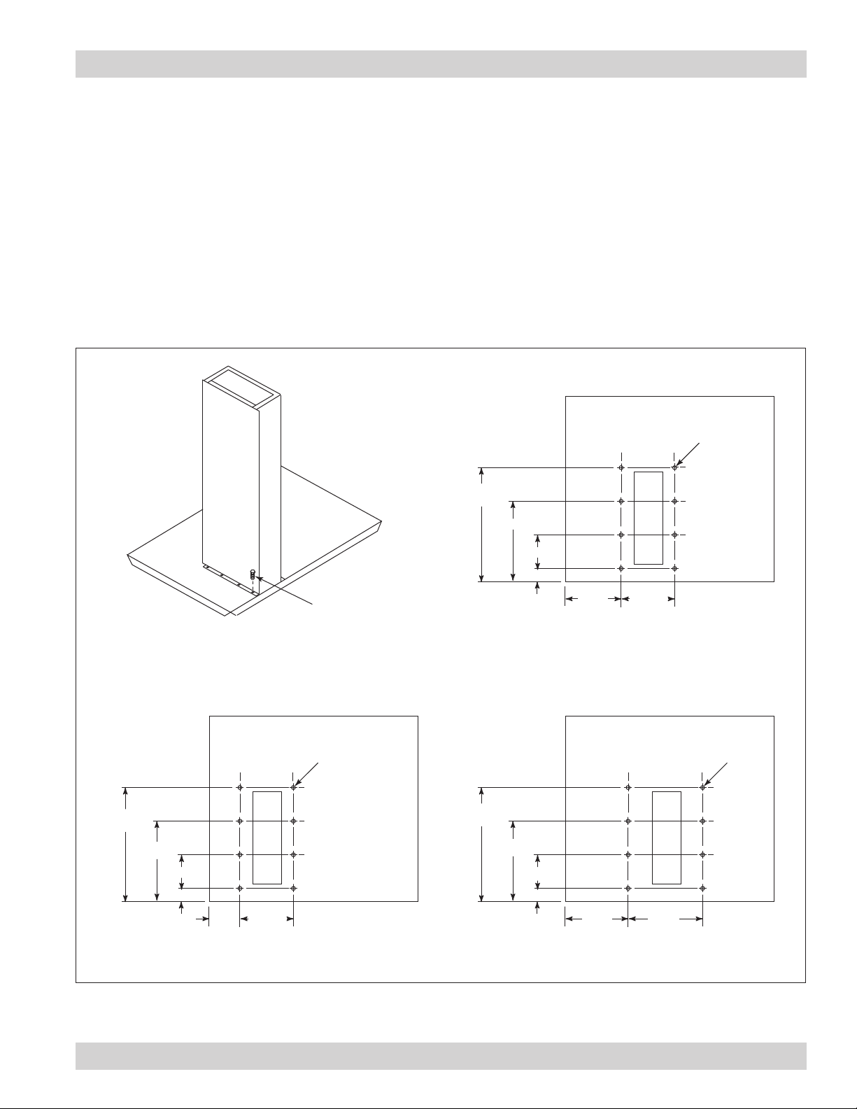
Exhaust Silencer
Cabinet Collector, Models 54-90
If an exhaust silencer was ordered with the collector, the
mounting holes are pre-drilled.
To install an add-on silencer:
1. Remove the top door assembly and set aside.
2. Place a piece of non-combustible cloth over the
filters in the clean-air chamber to protect them from
drilling chips.
3. Use a .116-in diameter drill bit to drill eight holes in
the collector top as shown.
4. Position the exhaust silencer, align holes, and fasten
securely with #7 x 1/2-in screws supplied.
5. Carefully remove the cloth protecting the filters.
Replace the top door assembly and tighten securely
by hand.
.116
8x
10.21
7.75
2.56
1.65
11.17
8.11
3.06
1.92
#7 x 1/2-in
self tapping screw
8 required
.116
8x
11.45
8.95
3.50
1.95
3.90 6.81
Series 60 and 70 Drill Location Series 80 Drill Location
5.24 5.06
Series 50 Drill Location
8.01 8.41
Exhaust Silencer Installation (only available on models 54-84)
.116
8x
28
Page 32

Donaldson Company, Inc.
Attenuator
If an attenuator was ordered with the collector, the
mounting holes are pre-drilled.
To install an add-on attenuator:
1. Remove the top door assembly and set aside.
2. Place a piece of non-combustible cloth over the
filters in the clean-air chamber to protect them from
drilling chips.
.213
8x
3. Use a .213-in diameter drill bit to drill eight holes in
the collector top as shown.
4. Position the attenuator assembly, align holes, and
fasten securely using eight 1/4-20 thread-cutting
screws supplied.
5. Carefully remove the cloth protecting the filters.
Replace the top door assembly and tighten securely
by hand.
Model A B
Series 50 14.50 8.50
Series 60 and 70 14.50 8.63
Series 80 18.00 8.63
6.81
6.81
Drill Location
6.81
B
6.81
A
attenuator
1/4-20 thread
cutting screw
8 required
Front View
29
Attenuator Installation (only available on models 54-84)
Page 33
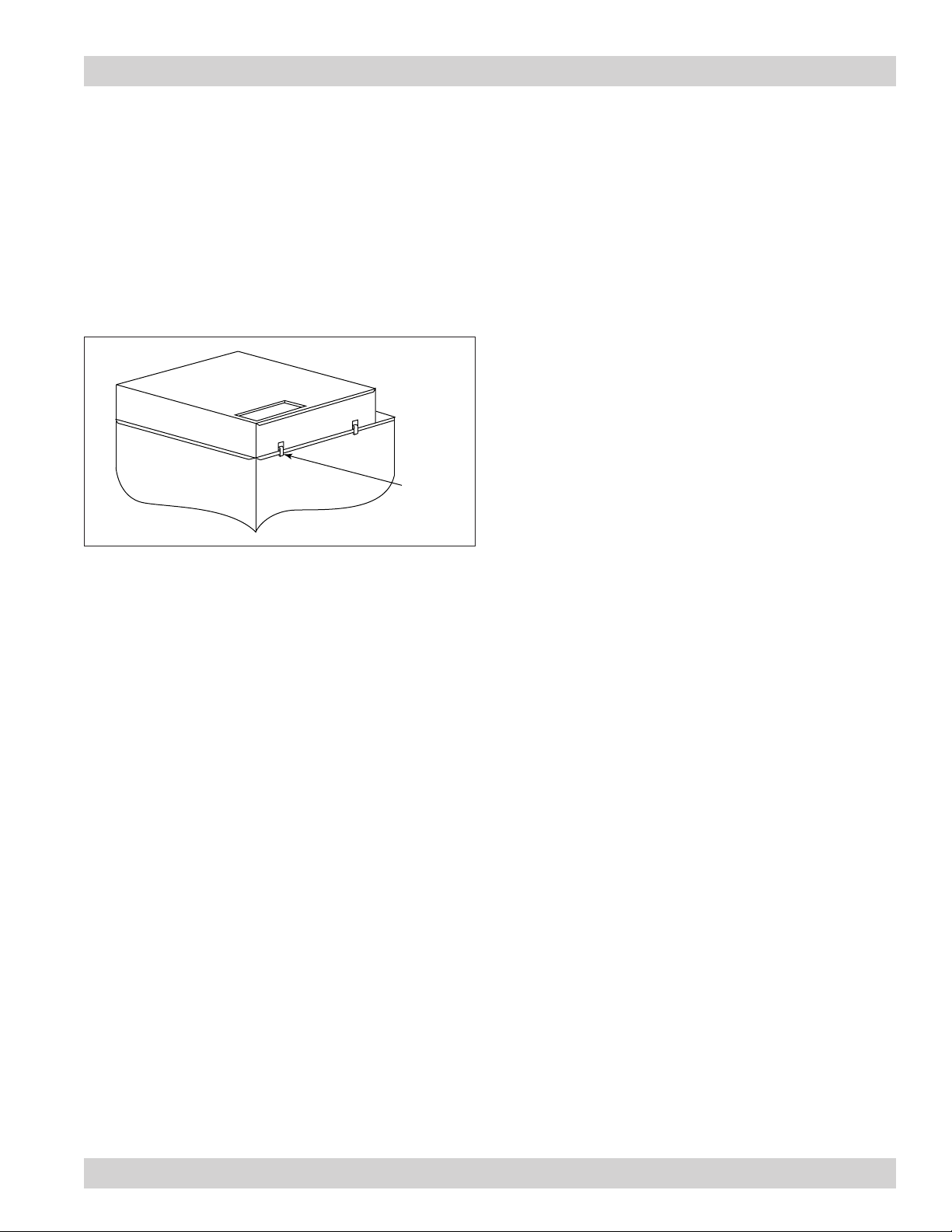
Chamber Silencer
1. Place the chamber silencer over the clean-air outlet
on top of the collector.
2. Position silencer flush with the front of the collector
and the exhaust opening facing the front.
3. Secure with all latches.
Cabinet Collector, Models 54-90
Front
latch
Chamber Silencer (only available on Models 54-84)
30
Page 34

Donaldson Company, Inc.
Troubleshooting
Problem Probable Cause Remedy
Fan blower and motor do
not start
Fan blower and motor
start, but do not stay
running
Insufficient airflow
Improper motor wire size Rewire using the correct wire gauge as specified by
national and local codes.
Not wired correctly Check and correct motor wiring for supply voltage.
See motor manufacturer's wiring diagram. Follow
wiring diagram and the National Electric Code.
Collector not wired for available
Correct wiring for proper supply voltage.
voltage
Input circuit down Check power supply to motor circuit on all leads.
Electrical supply circuit down Check power supply circuit for proper voltage.
Check for fuse or circuit breaker fault. Replace as
necessary.
Incorrect motor starter installed Check for proper motor starter and replace if
necessary.
Access doors are open or not
closed tight
Close and tighten access doors. See Filter
Installation.
Hopper discharge open Check that dust container is installed and properly
sealed.
Damper control not adjusted
properly
Check airflow in duct. Adjust damper control until
proper airflow is achieved and the blower motor’s
amp draw is within the manufacturer’s rated amps.
Electrical circuit overload Check that the power supply circuit has sufficient
power to run all equipment.
Inlet too large for collector
Contact installer of dust collection equipment.
rating
Fan rotation backwards Proper fan rotation is clockwise from the top of the
collector. The fan can be viewed through the back of
the motor. See Preliminary Start-Up Check.
Access doors open or not
closed tight
Check that all access doors are in place and
secured. Check that the hopper discharge opening is
sealed and that dust container is installed correctly.
Fan exhaust area restricted Check fan exhaust area for obstructions. Remove
material or debris. Adjust damper flow control.
31
Dust storage area overfilled or
plugged
Clean out dust storage area. See Dust Disposal.
Page 35

Cabinet Collector, Models 54-90
Problem Probable Cause Remedy
Insufficient airflow Collapsed or plugged duct Clean duct of all debris. Replace collapsed duct.
Improper duct sizing Contact installer of dust collection equipment.
EZ Filter Pack plugged Shake filter packs a minimum of once a day. Brush
or manually clean filter packs plugged with sticky or
fibrous material. Replace filter packs that do not clean
properly by shaking. See EZ Filter Pack Installation.
Manual shaker mechanism
Check that the roll pin is in place. Replace if necessary.
malfunctioning
32
Page 36

Donaldson Company, Inc.
Collector Information
(Process Owner to complete and retain for your records)
Model Number _____________________________ Serial Number ______________________________
Ship Date _________________________________ Installation Date _____________________________
Filter Type ____________________________________________________________________________
Dust Being Collected ___________________________________________________________________
Dust Properties: Kst _______________Pmax ______________ MIE ____________ MEC __________________
Accessories __________________________________________________________________________
Other ________________________________________________________________________________
____________________________________________________________________________________
33
Page 37

Service Notes
Date Service Performed Notes
Cabinet Collector, Models 54-90
34
Page 38

The Donaldson Torit Warranty
Donaldson warrants to the original purchaser that the major structural components of the goods will be free
from defects in materials and workmanship for ten (10) years from the date of shipment, if properly installed,
maintained and operated under normal conditions. Donaldson warrants all other Donaldson built components
and accessories including Donaldson Airlocks, TBI Fans, TRB Fans, Fume Collector products and Donaldson built
Afterfilters for twelve (12) months from date of shipment. Donaldson warrants Donaldson built filter elements to
be free from defects in materials and workmanship for eighteen (18) months from date of shipment. Donaldson
does not warrant against damages due to corrosion, abrasion, normal wear and tear, product modification,
or product misapplication. Donaldson also makes no warranty whatsoever as to any goods manufactured or
supplied by others including electric motors, fans and control components. After Donaldson has been given
adequate opportunity to remedy any defects in material or workmanship, Donaldson retains the sole option to
accept return of the goods, with freight paid by the purchaser, and to refund the purchase price for the goods
after confirming the goods are returned undamaged and in usable condition. Such a refund will be in the full
extent of Donaldson’s liability. Donaldson shall not be liable for any other costs, expenses or damages whether
direct, indirect, special, incidental, consequential or otherwise. The terms of this warranty may be modified
only by a special warranty document signed by a Director, General Manager or Vice President of Donaldson.
To ensure proper operational performance of the equipment, use only genuine Donaldson replacement parts.
THERE EXIST NO OTHER REPRESENTATIONS, WARRANTIES OR GUARANTEES EXCEPT AS STATED IN THIS
PARAGRAPH AND ALL OTHER WARRANTIES INCLUDING MERCHANTABILITY AND FITNESS FOR A PARTICULAR
PURPOSE, WHETHER EXPRESS OR IMPLIED ARE HEREBY EXPRESSLY EXCLUDED AND DISCLAIMED.
This product is provided subject to Donaldson’s Terms and Conditions of Sale, a copy of which is available on
our website or by calling our customer service line at 1-800-365-1331.
Parts and Service
For genuine Donaldson replacement filters and parts, call the Parts Express Line. For faster service,
have collector’s model and serial number, quantity, part number, and description available.
Donaldson Company, Inc.
Torit
PO Box 1299
Minneapolis, MN 55440-1299 U.S.A.
Donaldson Company, Inc. is the leading designer and manufacturer of dust, mist, and fume collection
equipment used to control industrial-air pollutants. Our equipment is designed to help reduce
occupational hazards, lengthen machine life, reduce in-plant maintenance requirements, and
improve product quality.
© 2002 Donaldson Company, Inc. IOM 7509401 (ENG), Revision 6
Printed in USA October 2017
800-365-1331 USA
800-343-3639 within Mexico
+52 (449) 300 24 42 Latin America
[email protected]
donaldsontorit.com
 Loading...