

Page 1
OPERATIONS
Timer Adjustment - Timer Models only
Isolate the power supply. Replace front cover BEFORE switching on the power supply.
The timer is factory set at midpoint. Time is set by placing the black bridge over 2 of the
pins on the right hand side of the timer board. If bridge is not fitted, timer will default to
20 minute setting. Replacement bridges are available from Silavent.
30 Mins 15 Mins 5 Mins
HUMIDITY ADJUSTMENT - HUMIDITY MODELS ONLY
Isolate the power supply. Replace the front cover and the humidity control adjustment
position is clearly marked. Turn clockwise for less sensitivity and anti-clockwise for
more sensitivity. Turn fully clockwise to turn the humidity sensor off. Replace front cover
BEFORE switching on the fan.
SVC 100 RANGE
VENTILAT ION
Installation Instructions
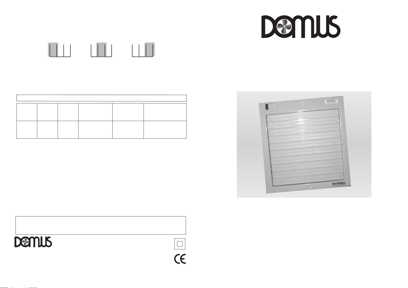
SVC100B Standard SVC100PB With Pull Cord
SVC100TB
CLEANING
Disconnect power supply before cleaning. It is important to clean fans annually as regular cleaning helps
maintain performance and ensure safe, reliable operation.
The front cover shutter can be removed from the fan and gently dusted with a soft brush or washed in
warm water with dishwashing liquid. Dry carefully before refitting.
IMPORTANT : Make sure that the shutter thermoactuator on the fan chassis is fully withdrawn (i.e. cold)
The interior of the fan can be dusted with a soft brush. Do not use water.
On humidity control models, please ensure that no water enters the sensor grille.
For window fitting, the SDF901WFK window kit is required.
230v AC - 50Hz 15W
Single Speed IPX4 Rating – This product is double insulated.
This appliance is not intended for use by persons (including children) with reduced physical, sensory or mental
capabilities, or lack of experience and knowledge, unless they have been given supervision or instruction
concerning use of the appliance by a person responsible for their safety.
With
Timer
SVC100HTB
before fitting the front cover shutter.
With Humidistat
and Timer
SVC100HTBPC
With Humidistat, Timer
and Pull Cord
SVC100
Shuttered
VENTILAT ION
Domus Ventilation
Cambria House, Caerphilly Business Park, Van Road, Caerphilly
CF83 3ED
Tel: +44 (0)3443 715523 Fax: +44 (0)3443 715524
Email: [email protected]
www.domusventilation.co.uk
ISSUE 2
09/17 LAB538R
Axial Wall / Window Fans
Page 2
SVC 100
Window / Wall Fan
These high quality extractor fans are designed to give effective ventilation and in order
to achieve this, please read these instructions carefully BEFORE installing the fan unit.
Failure to comply with these instructions could reduce the life of the product and may
invalidate the warranty.
This product is suitable for use with up to 2 metres of ducting.
WARNING: ISOLATE ELECTRICITY SUPPLY BEFORE STARTING WORK
FITTING WALL FAN
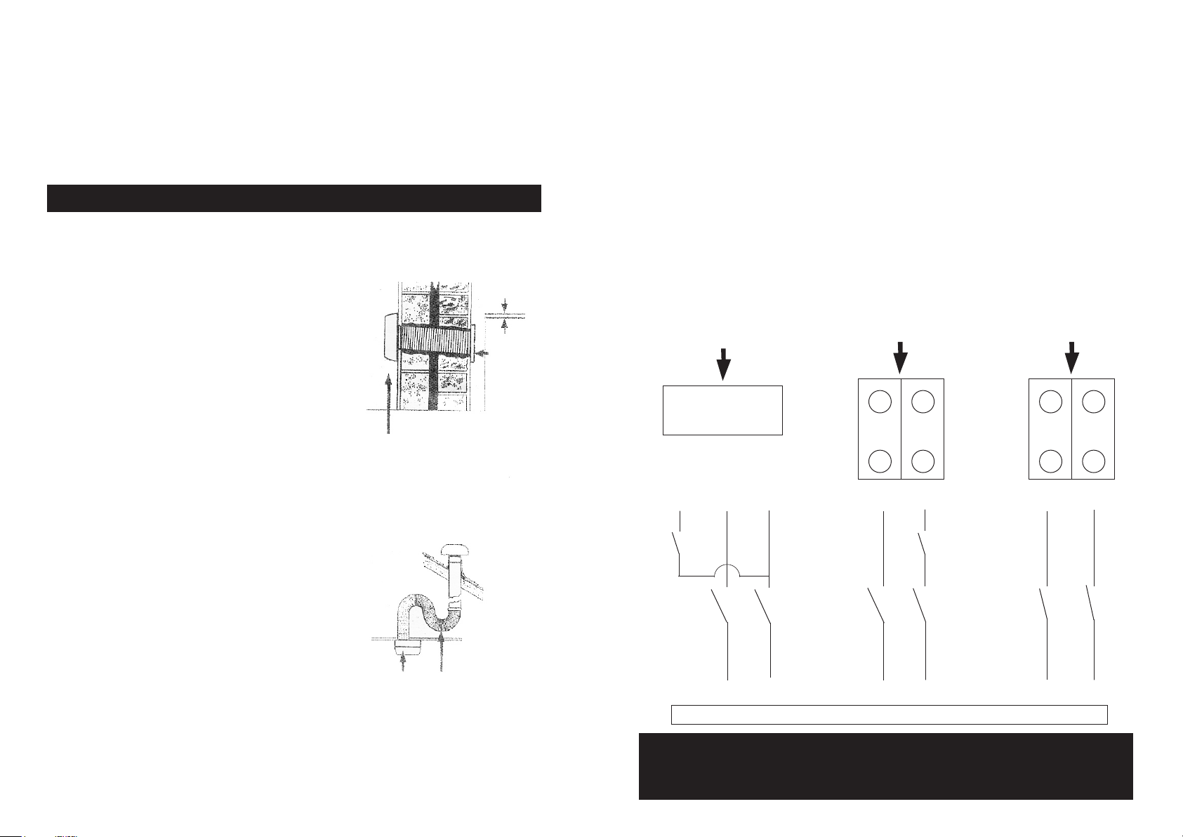
1. Select a suitable position for the fan in relation
to outside walls, ceilings and roofs, keeping the
FALL TO
OUITSIDE
ducting as short as possible – see Ducting.
2. Cut a hole in the wall or ceiling to take rear
spigot of fan plus ducting if fitted.
3. Remove the front cover from the fan by undoing
WALL
GRILLE
the retaining screw at the bottom edge of front
cover. Position the fan chassis and mark the
retaining screw positions.
4. Remove the appropriate cable entry knock out
FAN
position from the fan chassis and thread power
cable through before fixing the fan to the wall.
Note: Fans fitted with pull cord switches are not
suitable for ceiling mounting.
WIRING INSTRUCTIONS
It is recommended that the fans be connected into the lighting circuit, with double pole
(3mm) isolation provided before the room light switch and suitably fused, in accordance
with IEE Regulations.
Window fans should be connected to power supply using a flexible cord with conductors
of between 0.75mm2 and 1.5mm2 only. Wall and ceiling mounted fans for fixed wiring
should be connected to the power supply via a cable with solid conductors of 1mm2 to
1.5mm2 only.
CAUTION : Fans incorporating electronic control systems may be damaged if used in
conjunction with fluorescent lamps. If in doubt, we recommend you contact
Silavent customer services on
IF IN DOUBT CONSULT A QUALIFIED ELECTRICIAN
MODELS
SVC100TB
MODELS
SVC100B
MODELS
SVC100PB
SVC100HTB
SVC100HTBPC
To access terminals
on these models,
lift off control cover
S/L N L N L N L
DUCTING
1. Bring the ducting to the chosen locations and
trim its ends flush to the surfaces.
2. Note that there are 3 basic types of installation
and that condensation drainage should be
provided as shown. Ceiling location makes
drainage provision essential.
3. A small condensation trap should be made at
the lowest point of the ducting as shown it is
advisable to lag duct.
Note: All the ancillary items can be obtained through
Domus stockists.
call +44 (0) 3443 715 523
to find your nearest stockist
FAN
CONDENSATION
TRAP
Operating
Switch
Isolator
Switch
Isolator
Switch
S/L N L N L N L
L = LIVE N = NEUTRAL S/L = SWITCH LIVE
WARNING: ISOLATE ELECTRICITY SUPPLY BEFORE STARTING WORK
DO NOT INSTALL IN SHOWER CUBICLES
MAXIMUM ROOM TEMPERATURE 50ºC
 Loading...