

Page 1
1.0 Safety Informaon
Front view
269mm
134 mm*
269mm
137mm*
272mm
DX6GL (6 in ch)
Front view
DX9GL (9 in ch) DX12GL (12 inch)
Side view
Cable entry
Aperture required
184mm dia.
*To centre of
'duct'
337 mm
171 mm*
342mm
175mm*
342mm
Cable entry
*To centre of
'duct'
413mm
206mm*
420mm
214 mm*
420mm
Cable entry
*To centre
of 'duct'
Aperture required
260mm dia.
Aperture required
337mm dia.
269mm
272mm
DX6GL (6 in ch)
Front view
DX9GL (9 in ch) DX12GL (12 inch)
Side view
342mm
342mm
420mm
420mm
V E N T I L A T I O N
DX Window Fan Kit 50Hz/60Hz
Supply / Extract Units – Installaon and Maintenance
IMPORTANT: Installaon or replacement of units or spare parts must be carried out by a qualified
or Domus approved service engineer/ electrician and in accordance with IEE or local naonal wiring
regulaons.
2.0 Introducon
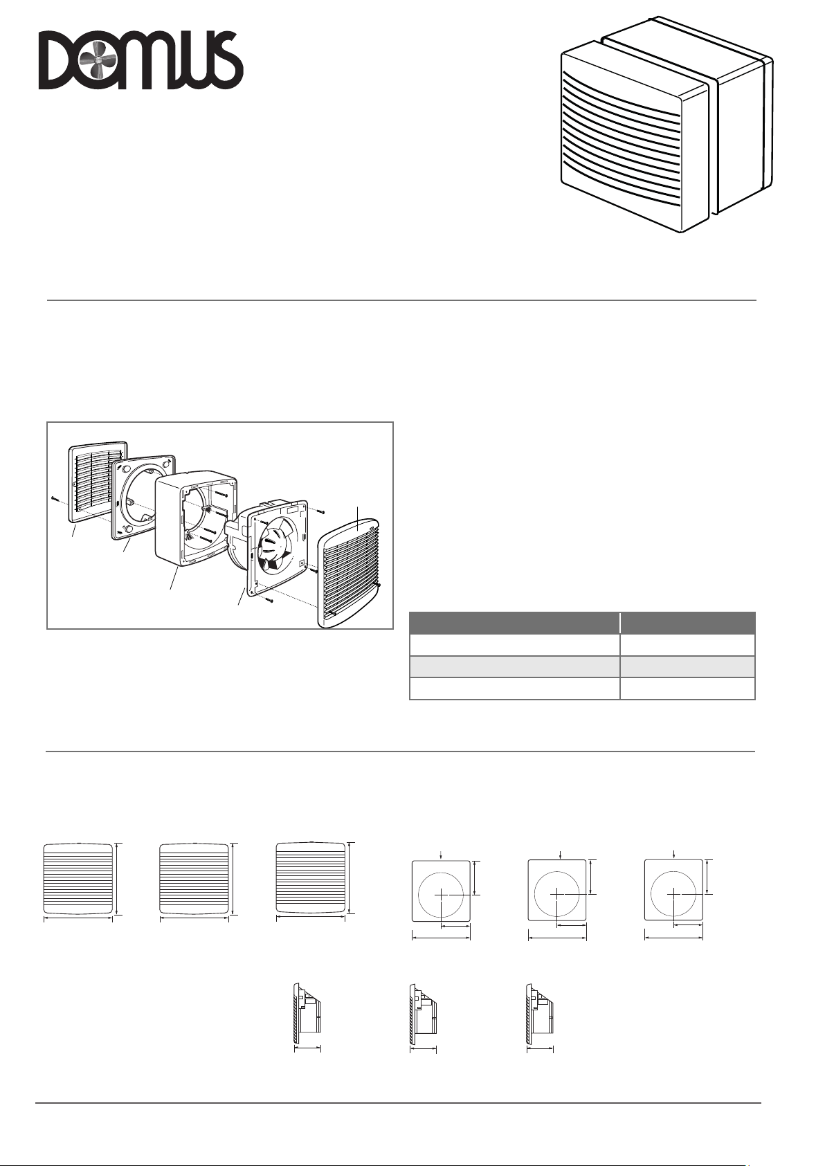
The Domus DX Window Fan Kit is available in 6, 9 and 12 inch impeller
sizes suitable for supply or extract and can be the heart of a room’s
automac venlaon system.
Ensure adequate air replacement for the fan and any fuel burning
appliance in the room.
Figure 1. Main components of Window installaon assembly.
Outer grille
Clamping plate
2.1 Switching
Operated via a separately wired 3 amp fused spur (by others) or operated
via the optional DX-CON remote controller allowing supply or extract,
variable speed and automatic or manual switching of several fans if
desired.
Spacer
Fan plate assembly
Inside grille
2.2 Sensors
Sensors are available as remote units or integral ‘plug in’ units. They
are able to control mulple fans, depending on sensor and fan types.
Integral sensors are quick and easy to install and are aesthecally
pleasing, whilst remote sensors give the benefit of locaon close to
the pollutant source. Remote sensors can be fied with an oponal
security strap to prevent unwanted tampering.
2.3 General
The removable interior grille provides easy access while the external
rotor motor makes for simple removal of the push-on impeller for
cleaning. Upward angled interior grille vanes shield workings from view
and downward sloping external vanes throw off rain. The fan is IP24
splash proof approved with the motor rated at IP44.
All external components are made in so grey colours from ultra violet
stable ABS material so they will blend with most decors and will not
fade in sunlight.
2.3.1 Coding For Window Fan Kits
Descripon Code*
6 inch Window Fan Kit Complete DX6WW
9 inch Window Fan Kit Complete DX9WW
12 inch Window Fan Kit Complete DX12WW
Window Fan Kits are supplied as a complete package with all
window installaon parts included and are suitable for glazing
thickness of up to 32mm and wall/panels of 360mm.
3.0 Dimensions
DX6WW (6 inch)
269mm
LAB1350R May
272mm
2018 Page 1
Figure 2.
DX9WW (9 inch) DX12WW
342mm
Rear view
342mm
( 12 inch)
420mm
128mm
420mm
Aperture required
184mm dia.
Cable entry
134 mm*
269 mm
130mm
137 mm*
*To centre of
'duct'
Aperture required
260mm dia.
Cable entry
171 mm*
337 mm
169 mm
175mm*
*To centre of
'duct'
Aperture required
337mm dia.
Cable entry
206 mm*
413mm
214 mm*
*To centre
of 'duct'
Page 2
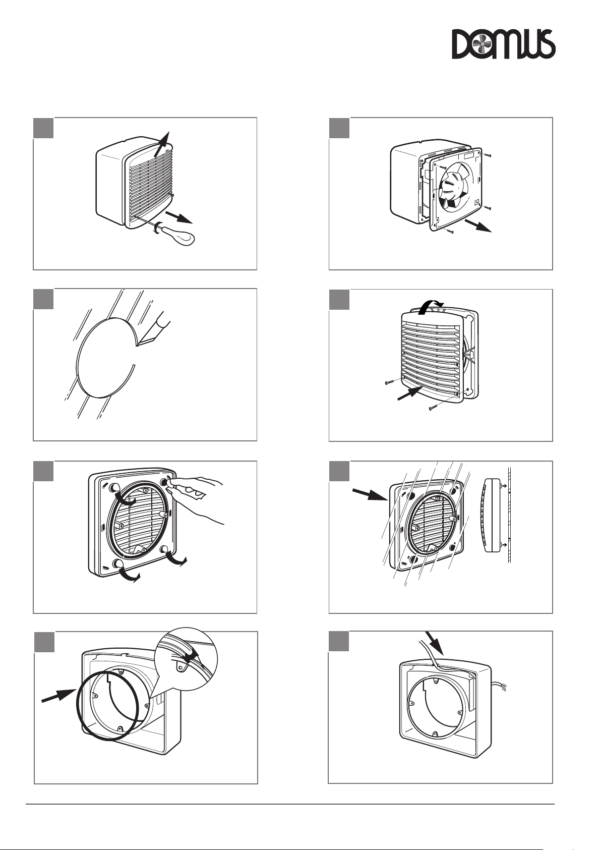
Clean the window glass and affix the
outer grille assembly over window aperture.
2
4
6
8
Feed supply cable into the case.
Remove fan plate.
Fix outer grille to spigot plate. Check plate orientaon is
vercal. N ote grille locates over top lugs on spigot plate.
Installation and Maintenance
DX Window Fan Kit 50Hz/60Hz
4.0 Installaon
4.1 Installaon of Window Fan Kits
1
Remove front grille.
Release 2 screws. Lift grille upwards.
3
Required Glass Aperture
DX6WW
DX9WW
XDX12WW
184 dia
260 dia
337 dia
V E N T I L A T I O N
2
Remove fan plate.
4
Prepare the window.
5
Remove adhesive pad covers.
7
Fix outer grille to spigot plate. Check plate orientaon is
vercal. Note grille locates over top lugs on spigot plate.
6
Clean the window glass and affix the
outer grille assembly over window aperture.
8
Ensure rubber seal is located into case spigot.
LAB1350R May 2018
Feed supply cable into the case.
Page 2
Page 3
Installation and Maintenance
10
12
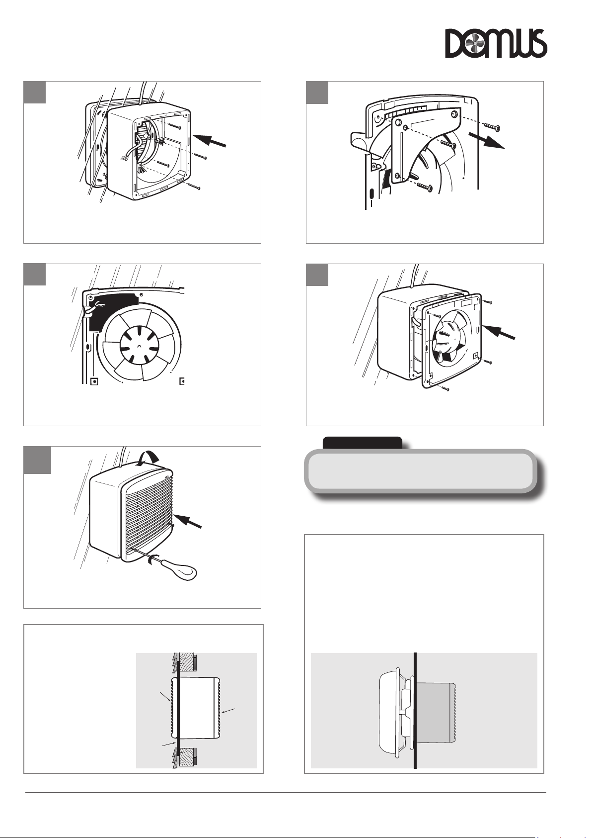
Release the electrical cover from the fan plate.
Assemble the fan plate to the case.
IMPORTANT
(Shuer Operaon XS fans)
There will be a short delay on start-up and shutdown of
approximately 40 seconds, this is normal.
4.2.2 WeatherTerminal
The oponal Weather Terminal is offered for use in exposed site
condions.
The illustraon shows the Weather Terminal installed replacing the
Outside Grille assembly.Terminal is held in posion using the same
fixings as the Outside Grille assembly. The base of the Terminal
incorporates a foam strip which is designed to adhere to the
glass surface assisng fing and also as a seal for the joint when
assembled together with the fan unit.
Glass
Main
Window
fan kit
Weather
Terminal
DX Window Fan Kit 50Hz/60Hz
9
Screw the case/ grille assembly together.
11
10
Release the electrical cover from the fan plate.
12
V E N T I L A T I O N
For various wiring opons see page 5.
13
Fit the inside grille, locang it over the top lip before
engaging screws.
4.2 Fing Ancillaries (Also see page 8)
4.2.1 Thin Wall Installaon
The diagram shows the unit
installed in a mber wall.
A Wall Fixing Plate is used
to support the fan assembly
and the installaon is similar
to that for a window.
Outside
Grille
Spacer
Wall
Fixing
Plate
Interior
Grille
Assemble the fan plate to the case.
IMPORTANT
There will be a short delay on start-up and shutdown of
(Shuer Operaon XS fans)
approximately 40 seconds, this is normal.
4.2.2 Weather Terminal
The oponal Weather Terminal is offered for use in exposed site
condions.
The illustraon shows the Weather Terminal installed replacing the
Outside Grille assembly. Terminal is held in posion using the same
fixings as the Outside Grille assembly. The base of the Terminal
incorporates a foam strip which is designed to adhere to the
glass surface assisng fing and also as a seal for the joint when
assembled together with the fan unit.
Glass
Weather
Terminal
Main
Window
fan kit
LAB1350R May 2018
Page 3
Page 4
Installation and Maintenance
accordance with the wiring regulaons.
2
4
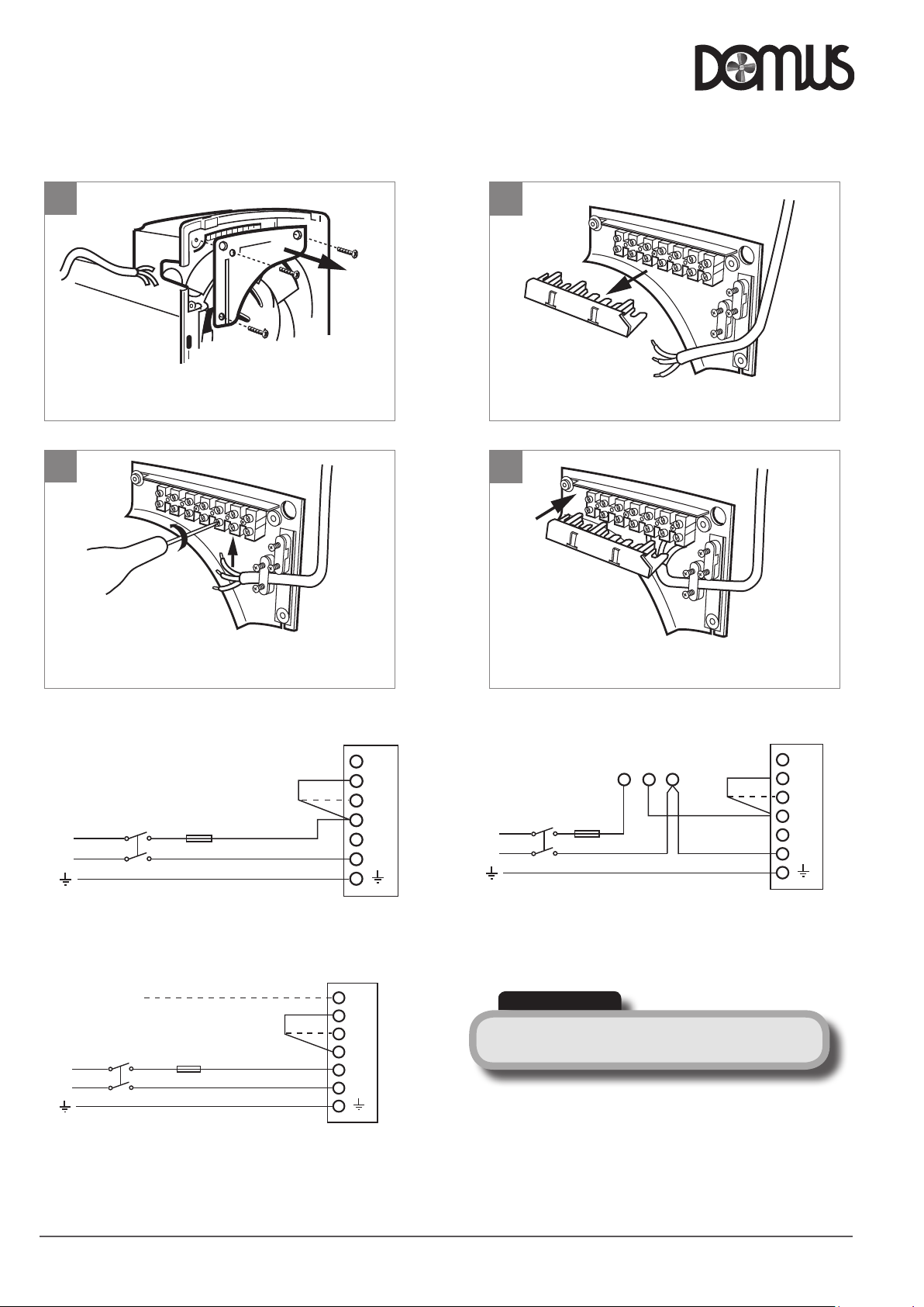
Remove the terminal cover.
Refit terminal cover before replacing the electrical panel.
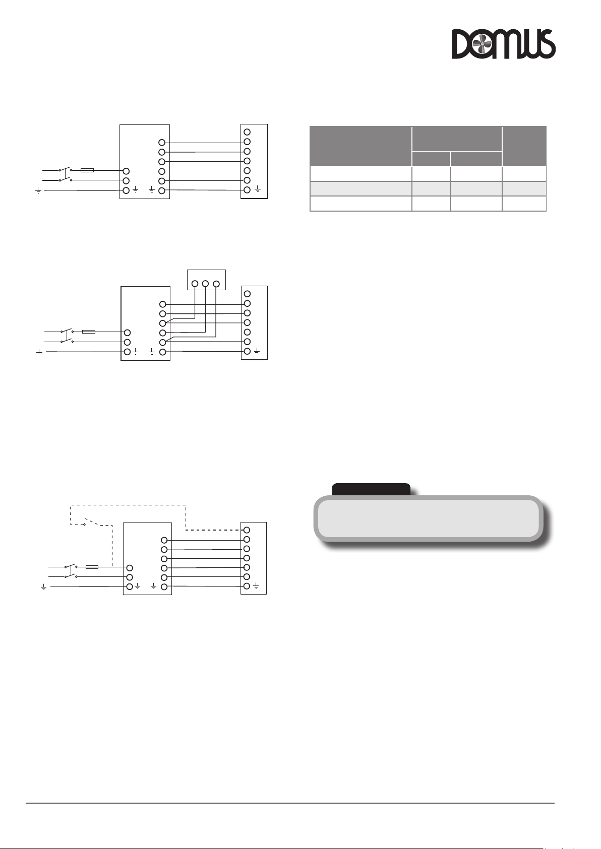
5.1.3 Basic Fan Operated By Remote Sensor
Double
pole
isolator
max.
Fuse
3 amp
Remote sensor
L5
L4
L3
L2
L1
N
or
L
N
DX Fan unit
L1 L2 N
Connect link wire between L2 & L4 for extract OR
connect link wire between L2 & L3 for supply.
IMPORTANT
Isolaon - Before commencing work, make sure that the unit is
electrically isolated from the mains supply.
DX Window Fan Kit 50Hz/60Hz
5.0 Electrical Installaon
5.0 Electrical Installaon
Electrical work should be undertaken by a qualified electrician in
Electrical work should be undertaken by a qualified electrician in accordance with the wiring regulaons.
1
Release the electrical panel from the fan plate.
3
2
Remove the terminal cover.
4
V E N T I L A T I O N
Clamp the cable and complete the connecons.
5.1 Wiring
5.1.1 Fan Operated By On / Off Switch
or
Double pole
isolator
L
N
Fuse
max. 3 amp
DX Fan unit
Connect link wire between L2 & L4 for extract OR
connect link wire between L2 & L3 for supply.
5.1.2 Fan Operated By Integral Sensor
SL
(Switched Live)
Double pole
isolator
L
N
Fuse
max. 3 amp
Connect link wire between L2 & L4 for extract OR
connect link wire between L2 & L3 for supply.
Connect switched live signal to L5 for integral mer module.
or
DX Fan unit with
integral sensor
Refit terminal cover before replacing the electrical panel.
5.1.3 Basic Fan Operated By Remote Sensor
L5
L4
L3
L2
L1
N
L5
L4
L3
L2
L1
N
Connect link wire between L2 & L4 for extract OR
connect link wire between L2 & L3 for supply.
Double
pole
isolator
L
N
IMPORTANT
Isolaon - Before commencing work, make sure that the unit is
electrically isolated from the mains supply.
Fuse
max.
3 amp
Remote sensor
L1 L2 N
or
L5
L4
L3
L2
L1
N
DX Fan unit
LAB1350R May 2018
Page 4
Page 5
Installation and Maintenance
IMPORTANT
(Shuer Operaon DX fans)
There will be a short delay on startup and shutdown of
approximately 40 seconds. This is normal.
Model
Input Power
(W)
Weight
(kg)
Max. Economy
DX6WW supply & extract 38 20 4.1
DX9WW supply & extract 50 37 5.7
DX12WW supply & extract 100 70 8.6
5.2 Unit Consumpon & Weight
5.3 Electrical Specificaon
230V ~ 50Hz / 220V ~ 60Hz Class I. Motor thermally protected by
overload device. Cable: 1mm max. or min. Fuse: 3 amp (if fan is supplied
from a 5A lighng circuit, no local fuse is required).
Note: If 2 x 12 inch fans or 3 x 6 or 9 inch fans are used in the same
operang mode in the same room they should all be controlled from
the same CON speed control. This avoids the possibility of one fan (if
speed controlled at a lower flow rate) being stalled by the other fan(s).
Adequate make-up air provision sufficient to provide venlaon in
accordance with building regulaons is required in all rooms. This
should be checked during commissioning with all fans in the same room
running together in all possible configuraons.
The automac shuers, motor bearings should be frequently inspected
and maintained to ensure they open fully/operate sasfactorily. Use
of an RCD and fused spur with 1A, BussmannTDC180, BS1362, fuse
(Farnell order no: 1123029) for 1 fan or 2A, Bussmann TDC180, BS1362
fuse (Farnell order no: 1123032) for 2 or 3 fans is recommended.
Always confirm airflow direcon before commissioning.
Note figures are for extract only at 50hz.
DX Window Fan Kit 50Hz/60Hz
5.1.4 Supply / Extract Fan Operated via remote DX-CON Control
Double
Fuse
pole
max.
isolator
L
N
mains
supply
3 amp
Remote switch may be set: On/Off, Supply/ Extract, Economy/Std.
(variable
speed), Auto/Manual.
5.1.5 Supply / Extract Fan Operated via remote DX-CON Control
Double
Fuse
pole
max.
isolator
L
N
mains
supply
3 amp
Remote switch may be set: On/Off, Supply/ Extract, Economy/Std.
(variable speed), Auto/Manual.
One or more Remote Sensors may be wired in parallel to one DX-CON
Control.
Humidity Sensor: DX-RH
5.1.6 Supply / Extract Fan Operated via remote DX-CON Control
Double
Fuse
pole
max.
isolator
3 amp
mains
supply
L
N
L4
L3
L2
L1
L1
N
N
DX-CON controller
L4
L3
L2
L1
NL1N
DX-CON controller
L4
L3
L2
L1
NL1N
DX-CON controller
Remote sensor
L2 L1 N
Required if using
integral Timer
DX Fan unit
DX Fan unit
DX Fan unit with
integral sensor
V E N T I L A T I O N
5.2 Unit Consumpon & Weight
L5
L4
L3
L2
L1
N
DX6WW supply & extract 38 20 4.1
DX9WW supply & extract 50 37 5.7
DX12WW supply & extract 100 70 8.6
Note figures are for extract only at 50hz.
Model
L5
L4
L3
L2
L1
N
5.3 Electrical Specificaon
230V ~ 50Hz / 220V ~ 60Hz Class I. Motor thermally protected by
overload device. Cable: 1mm max. or min. Fuse: 3 amp (if fan is supplied
from a 5A lighng circuit, no local fuse is required).
Note: If 2 x 12 inch fans or 5 x 6 or 9 inch fans are used in the same
operang mode in the same room they should all be controlled from
the same CON speed control. This avoids the possibility of one fan (if
speed controlled at a lower flow rate) being stalled by the other fan(s).
Adequate make-up air provision sufficient to provide venlaon in
accordance with building regulaons is required in all rooms. This
should be checked during commissioning with all fans in the same room
running together in all possible configuraons.
The automac shuers, motor bearings should be frequently inspected
and maintained to ensure they open fully/operate sasfactorily. Use
of an RCD and fused spur with 1A, Bussmann TDC180, BS1362, fuse
(Farnell order no: 1123029) for 1 fan or 2A, Bussmann TDC180, BS1362
fuse (Farnell order no: 1123032) for 2 or 3 fans is recommended.
Always confirm airflow direcon before commissioning.
L5
L4
L3
L2
L1
N
IMPORTANT
(Shuer Operaon DX fans)
There will be a short delay on startup and shutdown of
approximately 40 seconds. This is normal.
Input Power
(W)
Max. Economy
Weight
(kg)
Remote
switch may be set: On/Off, Supply/ Extract, Economy/Std.
(variable speed), Auto/Manual.
Maximum one Integral Sensor per fan, 6/9/12 denotes unit size identy.
Humidity Sensor: DX-H6/9/12
Passive I
nfra Red Sensor: DX-PIR6/9/12
Run on Timer: DX-T6/9/12.
A single sensor will switch all fans if mo re than one fan is being
operated by a single DX-CON controller.
NOTE: M
ul-fan opons:
Up to 5 fans (size 6"/9") can be controlled by one DX-CON.
Up to 2 fans (size 12") can be controlled by one DX-CON.
Do not mix different fan sizes on the same controller.
LAB1350R May 2018
Page 5
Page 6
Installation and Maintenance
Screw the sensor module into posion.
1
3
5
7
Push the repacement cover into the grille front.
Lift out the sensormodule wiring connector.
Unscrew the module plate from motor plate assy.
DX Window Fan Kit 50Hz/60Hz
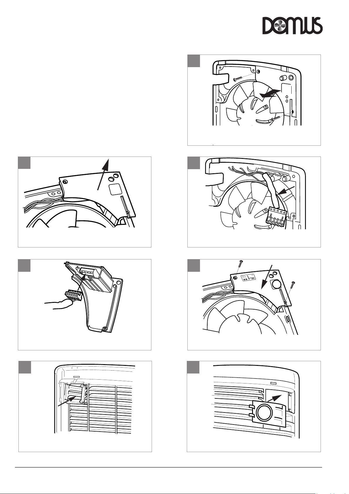
5.4 Fing Integral Sensors (Oponal)
Note: Before following the pictorial sequence shown, first remove the
fans front cover grille (2 screws). Release the four main corner screws
and li out the motor/fan plate assembly. Remove the electrical cover
plate opposite the sensor plate. Follow the pictorial sequence on this
page.
2
1
Unscrew the module plate from motor plate assy.
3
V E N T I L A T I O N
Remove the module plate.
4
Plug the connector into the required sensor module.
6
Lift out the sensor module wiring connector.
5
Screw the sensor module into posion.
7
Push out the sensor area cover from the grille.
LAB1350R May 2018
Push the repacement cover into the grille front.
Page 6
Page 7
Installation and Maintenance
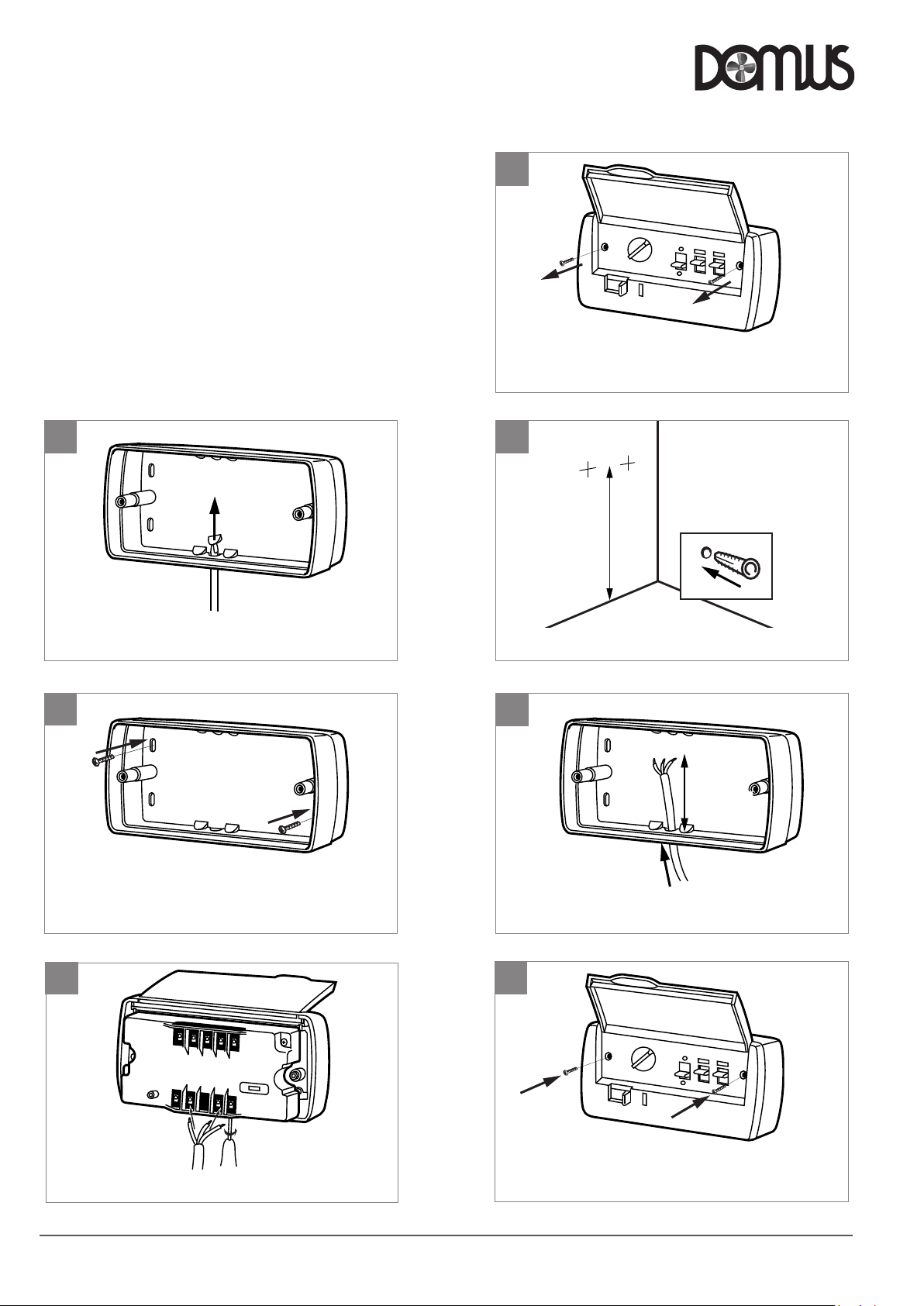
Feed approx. 200mm of supply cable into the box
1
3
5
7
Fit the control into the backplate box and secure.
Test the installaon.
Lift up panel and remove two screws to dismantle unit.
Spot through backplate box and drill and plug the wall.
200mm
1.5m
DX Window Fan Kit 50Hz/60Hz
5.5 Fing Remote Controller DX-CON or
Remote sensors (oponal)
The DX-CON Mul Fan Control provides supply or extract, variable
speed and automac or manual switching of several fans if desired, (see
note below). The control is best mounted approx 1.5m above the floor.
Remote Sensors are available for Humidity, Air Quality and Passive Infra
Red control. Remote Sensors should be posioned at least 1.5m above
the floor and away from direct heat sources e.g. radiators.
Note:
Up to 5 fans (size 6 / 9 inch) can be controlled by one DX-CON.
Up to 2 fans (size 12 inch) can be controlled by one DX-CON.
Do not mix different fan sizes on the same controller.
2
1
Lift up panel and remove two screws to dismantle unit.
3
1.5m
V E N T I L A T I O N
Push out backplate box cable entry using a screwdriver.
4
Fix backplate box to the prepared wall.
6
Spot through backplate box and drill and plug the wall.
5
Feed approx. 200mm of supply cable into the box
7
200mm
Connect the end of the cable into the control block.
LAB1350R May 2018
Fit the control into the backplate box and secure.
Test the installaon.
Page 7
Page 8
Installation and Maintenance
DX Window Fan Kit 50Hz/60Hz
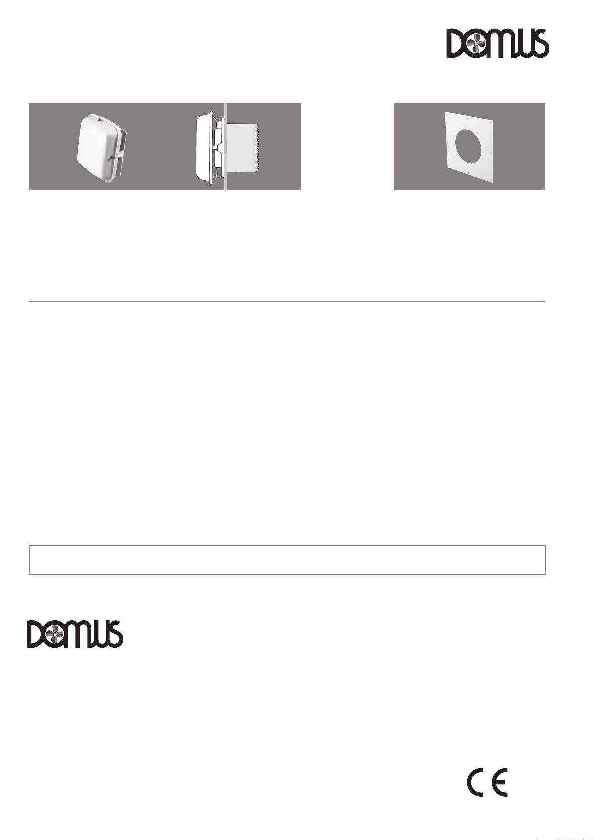
6.0 Ancillaries
Glass
Weather
Terminal
Weather Terminal
Used for exposed site wall
installaons, comprising one
weather terminal, manufactured
from HIPS.
Order Code DX-WT6
Dimensions: 360 x 360 x 170mm
7.0 Maintenance
Periodically, at least once a year or more frequently in case of heavy
use, remove the dirt and encrustaon from the grille(s) fan impeller
and motor casing. Ensure the impeller is not cracked or deformed and is
able to rotate freely and without oscillaon.
Do not use any solvents to clean this product.
The Weather terminal unit replaces
the outside grille and is supplied
with installaon details.
Order Code DX-WT9
Dimensions: 425 x 425 x 180mm
V E N T I L A T I O N
Main
Window
fan kit
Wall Fixing Plate
The Wall Fixing Plate is used for thin wall
and above ceiling applicaons, to support
the fan assembly.
Order Code DX-WT12
Dimensions: 506 x 506 x 185mm
9.0 Warranty
The 2 year warranty starts from the day of deli very and includes parts
and labour for the first year. The remaining period covers replacement
parts only.
This warranty is void if the equipment is modified without
authorisaon, is incorrectly applied, misused, disassembled, or not
installed, commissioned and maintained in accordance with the details
contained in this manual and general good pracce.
8.0 Replacement Of Parts
As a manufacturer Domus is aware that me is important. In the event
of a breakdown of this equipment, it should be adequately packaged
and returned to Domus.
Please telephone Domus before posng your unit. A returns number will
be issued to idenfy your package.
We will endeavour to repair or replace it within five working days of
receipt. See our warranty terms.
Technical or commercial consideraons may, from me to me, make it necessary to alter the design, performance and dimensions of equipment
and the right is reserved to make such changes without prior noce.
The product warranty applies to the UK mainland and in accordance
with Clause 14 of our Condions of Sale.
Customers purchasing from outside of the UK should contact Domus
Internaonal Sales office for further details. A unit returned to Domus
should be suitably protecvely packaged and clearly marked with the
‘returns number’ obtained from Domus prior to posng.
10.0 Aer Sales Enquiries
For technical assistance or further product informaon, including spare
parts and replacement components, please contact the Aer Sales
Department.
V E N T I L A T I O N
Domus Ventilation
Block C
Caerphilly Business Park
V an Road
Caerphilly
CF83 3ED
T el: +44 (0)3443 715523
Fax: +44 (0)3443 715524
Email: [email protected]
www.domusventilation.co.uk
The EMC Directive
2014/30/EU
The Low Voltage
Directive
2014/35/EU
LAB1350R May 2018
Page 8
 Loading...