

GRID
AC INPUT
230V AC
OUTPUT
POW
OLP
OVP
UVP
AC INPUT
CIRCUIT
BREAKER
ENDEFR
ES
PT
IT
NL
DASVNOFIRUPLSKCSHU
ENERGY & LIGHTING
PERFECTPOWER
PP1002, PP1004, PP2002, PP2004
Inverter with mains priority circuit
Installation and Operating Manual. . . . . . . . 6
Wechselrichter mit
Netz-Vorrangschaltung
Montage- und Bedienungsanleitung . . . . .23
Onduleur avec commutation
prioritaire du secteur
Instructions de montage
et de service . . . . . . . . . . . . . . . . . . . . . . . . . 41
Inversor de onda sinusoidal con
conmutador de red de prioridad
Instrucciones de montaje y de uso. . . . . . .59
Conversor com ligação prioritária
de rede
Instruções de montagem e manual de
instruções . . . . . . . . . . . . . . . . . . . . . . . . . . .77
Inverter con commutazione di
priorità di rete
Istruzioni di montaggio e d’uso . . . . . . . . .95
Inverter met
netvoorrangsschakeling
Montagehandleiding en
gebruiksaanwijzing. . . . . . . . . . . . . . . . . . 113
Ensretter med prioritetskobling
til net
Monterings- og betjeningsvejledning. . . 131
Växelricktare med
nät-prioritetomkoppling
Monterings- och bruksanvisning . . . . . . . 149
Vekselretter med
nettprioritetskobling
Monterings- og bruksanvisning. . . . . . . . 166
Verkkoetusijaiskytkennällä
varustettu vaihtomuunnin
Asennus- ja käyttöohje . . . . . . . . . . . . . . . 183
Инвертор c приоритетной сетевой
схемой
Инструкция по монтажу и эксплуатации 201
Przetwornica z sieciowym
przełącznikiem pierwszeństwa
Instrukcja montażu i obsługi. . . . . . . . . . .220
Menič napätia so sieťovým
prioritným spínaním
Návod na montáž a uvedenie
do prevádzky. . . . . . . . . . . . . . . . . . . . . . .238
Měnič s prioritním síťovým
spínáním
Návod k montáži a obsluze . . . . . . . . . . .257
Inverter hálózati elsőbbségi
kapcsolással
Szerelési és használati útmutató . . . . . . . 274

PerfectPower
1
2
A
B
3
321 4
GRID
AC INPUT
AC INPUT
CIRCUIT
BREAKER
123 4 675
ON
OFF
REMO.
230V AC
OUTPUT
DC INPUT
REVERSE POLARITY
WILL DAMAGE UNIT
NEG– POS+
POWER
OLP
UVP
OVP
5
6
7
8
AB
3
PerfectPower
FG
J3
N + FG
FG
J3
N + FG
1
22
PP1000 PP2000
3
4
5
3
4
5
4
Status
Power
Level
Load
Level
Input
1.
2.
5
4
PerfectPower
6
7
Output
FI 1
230 Vw
RCD
L1
N
PE
L!
N
PE
L1
N
PE
2
654
FI 2
RCD
Input
230 Vw
DC
PerfectPower
PE
L1
N
DC
Input
230 Vw
1
3
5

EN
PerfectPower
Please read this instruction manual carefully before installation and first
use, and store it in a safe place. If you pass on the product to another
person, hand over this instruction manual along with it.
Table of contents
1 Explanation of symbols. . . . . . . . . . . . . . . . . . . . . . . . . . . . . . . . . . . . . . . . . . .7
2 General safety instructions . . . . . . . . . . . . . . . . . . . . . . . . . . . . . . . . . . . . . . . .7
3 Scope of delivery . . . . . . . . . . . . . . . . . . . . . . . . . . . . . . . . . . . . . . . . . . . . . . .8
4 Accessories . . . . . . . . . . . . . . . . . . . . . . . . . . . . . . . . . . . . . . . . . . . . . . . . . . . .9
5 Target group for this manual. . . . . . . . . . . . . . . . . . . . . . . . . . . . . . . . . . . . . . .9
6 Intended use . . . . . . . . . . . . . . . . . . . . . . . . . . . . . . . . . . . . . . . . . . . . . . . . . . .9
7 Technical description . . . . . . . . . . . . . . . . . . . . . . . . . . . . . . . . . . . . . . . . . . . 10
8 Fastening and connecting the inverter . . . . . . . . . . . . . . . . . . . . . . . . . . . . .12
9 Using the inverter . . . . . . . . . . . . . . . . . . . . . . . . . . . . . . . . . . . . . . . . . . . . . .17
10 Cleaning and caring for the inverter. . . . . . . . . . . . . . . . . . . . . . . . . . . . . . . . 18
11 Rectifying faults . . . . . . . . . . . . . . . . . . . . . . . . . . . . . . . . . . . . . . . . . . . . . . . .19
12 Guarantee . . . . . . . . . . . . . . . . . . . . . . . . . . . . . . . . . . . . . . . . . . . . . . . . . . . 20
13 Disposal . . . . . . . . . . . . . . . . . . . . . . . . . . . . . . . . . . . . . . . . . . . . . . . . . . . . . 20
14 Technical data . . . . . . . . . . . . . . . . . . . . . . . . . . . . . . . . . . . . . . . . . . . . . . . . . 21
6

EN
PerfectPower Explanation of symbols
1 Explanation of symbols
WARNING!
!
A
I
Safety instruction: Failure to observe this instruction can cause fatal or
serious injury.
NOTICE!
Failure to observe this instruction can cause material damage and impair
the function of the product.
NOTE
Supplementary information for operating the product.
2 General safety instructions
The manufacturer accepts no liability for damage in the following cases:
• Faulty assembly or connection
• Damage to the product resulting from mechanical influences and excess voltage
• Alterations to the product without express permission from the manufacturer
• Use for purposes other than those described in the operating manual
2.1 General safety
WARNING!
!
• Use the device only as intended.
• Maintenance and repair work may only be carried out by qualified
personnel who are familiar with the risks involved and the relevant
regulations.
• People (including children) whose physical, sensory or mental
capacities or whose lack of experience or knowledge prevent them
from using this product safely should not use it without the supervision
or instruction of a responsible person.
• Electrical devices are not toys!
Always keep and use the device well out of the reach of children.
7

EN
Scope of delivery PerfectPower
2.2 Safety when installing the device
WARNING!
!
• Installing the device may only be performed by qualified personnel
who are familiar with the guidelines and safety precautions to be
applied.
• If electrical devices are incorrectly installed on boats, corrosion damage might occur. The device should be installed by a specialist
(marine) electrician.
2.3 Operating the device safely
WARNING!
!
Note the following basic safety information when using electrical
devices to protect against:
• Electric shock
• Fire hazards
• Injury
• Operate the device only if you are certain that the housing and the
cables are undamaged.
• Make sure the air inlets and outlets of the device are not covered.
• Ensure good ventilation. The inverter produces dissipated heat which
has to be diverted.
• Always disconnect the power supply when working on the device.
3Scope of delivery
Quantity Designation
1Inverter
1 230 V connection cable
4 Mounting brackets
1 Mounting plate
2 Cable terminal
1 Operating manual
8

EN
PerfectPower Accessories
4Accessories
Available as accessories (not included in the scope of delivery):
Description Ref. no.
Remote control MCR9 9600000091
If you have questions in respect of the accessories, please contact your local service
partner.
5 Target group for this manual
The chapter “Connecting the inverter” on page 13 is solely intended for qualified
professionals who are familiar with the relevant VDE (German Engineering Society)
regulations!
All other chapters are intended for the users.
6 Intended use
WARNING!
!
Never use the inverter on vehicles where the positive terminal of the
battery is connected to the chassis.
Inverters PP1002, PP1004, PP2002 and PP2004 are used for supplying power to
230 V consumers with a 12 V or 24 V power supply:
• 12 V: PP1002 and PP2002
• 24 V: PP1004 and PP2004
The inverters are suitable for use in caravans, commercial vehicles and motor and
sailing vessels.
9

EN
Technical description PerfectPower
7 Technical description
Inverters PP1000 and PP2000 consist of two function units:
• Inverter switch: generates 230 Vw power from a battery voltage of
– 12 V: PP1002 and PP2002
– 24 V: PP1004 and PP2004
• Mains priority circuit: switches automatically between 230 V of external mains
voltage (e.g. on a camping site) and a battery generated 230 V power supply
The external supply has priority. If no more external voltage is available, the
output socket is disconnected from the external power supply and connected to
the inverter voltage. This ensures that the output socket always has a power
supply of 230 V.
From inverter operation to mains power supply:
There is a delay when switching from inverter operation (whereby the 230 Vw
power is produced from the battery voltage) to the mains power supply.
When the plug is inserted in the outside socket (camping site, harbour) the
inverter is switched off after a delay of approx. 4 s. After a further 2 s, the mains
power supply is switched through. This gives the devices connected enough
time to switch off properly.
From mains power to inverter operation:
A delay also occurs when switching from mains power to inverter operation.
If the mains supply fails, the inverter switches on after 2 seconds.
NOTICE!
A
The inverter is equipped with protection against thermal and electrical overloading,
as well as excess and insufficient voltage. The inverter switches off:
• If its internal temperature is too high
• If the load exceeds the values listed in the technical data
• If the input voltage is too high or too low
A single consumer or a socket distribution system can be connected to the inverter
to create an on-board 230 V supply with several sockets.
When switching over, any devices connected should be switched off.
Because they do not receive voltage for 2 s, they may have to be
switched back on.
10

EN
PerfectPower Technical description
The device is equipped at delivery with galvanic isolation. For the safe operation of
multiple consumers, it is essential that a circuit breaker (residual current circuit
breaker) is built into the socket distribution circuit and the grounding bridge is set in
the inverter.
NOTE
I
The inverter can be switched on manually or using a remote control.
Cooling is provided by a fan and is load-dependent.
Note when connecting devices with an electrical drive (such as power
drills and refrigerators), that they often need more power than is stated
on the type plate.
7.1 Control elements
NOTE
I
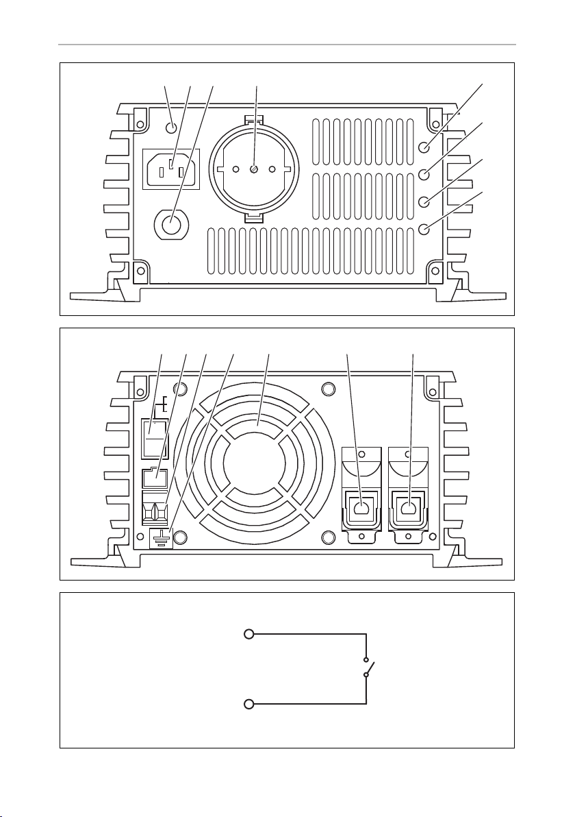
Front view (fig. 1, page 3)
The version for continental Europe is pictured.
No. Description
1 Grid: This LED lights up if the inverter is supplied with external 230 V mains
power; the priority circuit is active.
2 Connection for the external 230 V power supply
3 Circuit breaker: Fuse
4 230 Vw output
5 POWER: This LED lights up when the inverter is switched on.
6 OLP: This LED lights up when the consumers connected draw too much
electricity.
7 UVP: This LED lights up when battery capacity is too weak.
8 OVP: This LED lights up when the input voltage is too high.
11

EN
Fastening and connecting the inverter PerfectPower
Rear view (fig. 2, page 3)
No. Description
1 Main switch
2 Connection for MCR9 remote control
3 Connection for an external switch contact
4 Earth connection
5Fan
6 Negative terminal
7 Positive terminal
8 Fastening and connecting the inverter
8.1 Fastening the inverter
WARNING!
!
• Ensure the device is standing firmly.
Set up the device securely and fasten it in such a way that
– it cannot tip over or fall down
– it cannot move while the vehicle is in motion
• Take precautions necessary to ensure that it is out of reach of
children. Dangerous situations may occur which cannot be
recognised by children!
You can fasten the inverter using the holders supplied.
When selecting the installation location, observe the following instructions:
• Do not operate the device
– in wet or damp environments
– in dusty environments
– in the vicinity of flammable materials
– in spaces where there is a danger of explosion
• Do not expose the device to a heat source (such as direct sunlight or heating).
Avoid additional heating of the device in this way.
• Make sure the cables are the correct length and choose the installation location
near the battery supply.
12

EN
PerfectPower Fastening and connecting the inverter
• Select a well-ventilated location for the device.
A ventilation system must be present for installations in small, enclosed spaces.
• Make sure that the air intake on the front of the inverter remains clear.
• Select a mounting surface which is flat and sufficiently firm.
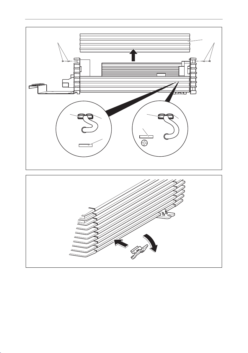
Fasten the inverter as follows (fig. 5, page 4):
NOTICE!
A
➤ Clip two holders on the left bar and two on the lower right bar.
You can move the holders as required.
➤ Fasten the inverter by screwing one screw through each hole in the holder.
8.2 Connecting the inverter
!
Before drilling any holes, make sure that no electrical cables or other
parts of the vehicle can be damaged by drilling, sawing and filing.
WARNING!
The inverter may only be connected by a qualified workshop.
The following information is intended for specialists who are familiar with
the guidelines and safety precautions to be applied.
Observe the following safety instructions for the electrical connections:
NOTICE!
A
• Caution – Risk of short circuit!
When working on the vehicle, always disconnect the earth
connection to the supply battery.
• Disconnect the 230 V external power supply to the caravan.
• If you have to feed cables through metal walls or other walls with
sharp edges, use ducts or tubes to prevent damage.
• Do not lay cables which are loose or bent next to electrically
conductive material (metal).
• Fasten the cables securely.
• Do not pull on the cables.
• Do not lay the 230 V mains cable and the 12/24 V DC cable in the
same duct.
• Lay the cables so that they cannot be tripped over or damaged.
13

EN
Fastening and connecting the inverter PerfectPower
WARNING! Danger of electrocution!
!
Earthing the inverter
➤ Connect the earth connection on the inverter (fig. 2 4, page 3) with the earth of
the vehicle.
Connecting the inverter to the battery
I
A
➤ Connect the terminal on the red battery connection cable to the positive terminal
(fig. 2 7, page 3) on the inverter.
If you wish to connect more than one consumer to the inverter and install
a socket distributor loop, you must arrange a circuit breaker (residual
current circuit breaker) and set a grounding bridge in the inverter, see
chapter “Connecting multiple consumers” on page 15.
NOTE
Please be aware that all volatile memories of the connected electric consumers will lose their stored data if the battery is disconnected.
NOTICE!
Make sure the polarity is correct. If the positive and negative
connections are reversed, this may damage the device.
➤ Connect the terminal on the black battery connection cable to the negative
terminal (fig. 2 6, page 3) on the inverter.
➤ Check the connections are secure.
You might have to tighten the screws again later.
NOTE
I
➤ Connect the red battery connection cable to the positive terminal on the battery.
➤ Connect the black battery connection cable to the negative terminal on the
battery.
14
Sparks may be produced when the connections are made due to the
internal capacitors being charged.

EN
PerfectPower Fastening and connecting the inverter
Connecting the inverter to the 230 V mains supply
➤ Plug the 230 V connection cable into the connector for the 230 V power supply
to the inverter (fig. 1 2, page 3).
➤ Connect the 230 V connection cable to a 230 V socket in the vehicle.
Connecting the remote control to the inverter
➤ Switch off the inverter.
➤ Insert the cable end of the remote control into the connection (fig. 2 2,
page 3).
➤ Set the main switch (fig. 2 1, page 3) to “Remote”.
Connecting the external switch contact to the inverter
➤ Switch off the inverter.
➤ Connect the external switch contact (power supply from the inverter) at the
remote port (fig. 2 3, page 3) in accordance with the wiring diagram (fig. 3,
page 3),
➤ Set the main switch (fig. 2 1, page 3) to “Remote”.
NOTE
I
If you wish to use an external switch contact with a power supply of it
own, e.g. the ignition, you must interconnect a suitable relay.
8.3 Connecting multiple consumers
WARNING! Danger of electrocution!
!
The device is equipped at delivery with galvanic isolation. For the safe operation of
multiple consumers, it is essential that a circuit breaker (residual current circuit
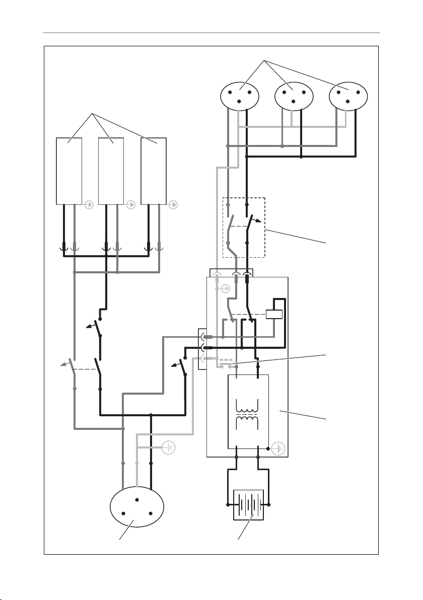
breaker) is built into the socket distribution circuit, see sample circuit diagram in
fig. 6, page 5.
If you wish to connect more than one consumer to the inverter and install
a socket distribution circuit, you must arrange a circuit breaker (residual
current circuit breaker) and set a grounding bridge in the inverter. The
grounding bridge may only be connected by a trained professional who
is familiar with the relevant VDE (German Engineering Society) regulations.
15

EN
Fastening and connecting the inverter PerfectPower
Sample circuit diagram legend:
No. in fig. 6,
page 5
1 230 Vw power source
2 Additional devices, e.g. battery charger, refrigerator
3 DC power source (battery)
4Inverter
5 Grounding bridge set
6 Circuit breaker (residual current circuit breaker)
7 Socket distribution circuit for consumers
➤ Install a residual current circuit breaker in the socket distribution circuit.
Setting grounding bridge (fig. 4, page 4)
WARNING! Danger of electrocution!
!
I
The grounding bridge may only be connected by a trained professional
who is familiar with the relevant VDE (German Engineering Society)
regulations.
NOTE
The grounding bridge plug is always plugged into socket “FG”
(insulated AC current) when delivered.
Explanation
(At delivery: not set, shown by dotted line)
➤ Unscrew the top four fastening screws (2) on the front of the device with a hex
key.
➤ Take off the cover (1).
NOTICE!
A
➤ Remove the plug (3) from socket “FG” (4).
➤ Insert the plug (3) into socket “N + FG” (5).
➤ Replace the device cover (1) and fix using the screws (2).
The grounding bridge is changed with sockets “FG” and “N + FG”. Do
not alter the other sockets, otherwise the device may be damaged.
16

EN
PerfectPower Using the inverter
9Using the inverter
NOTICE!
A
A
When using the inverter, observe the following instructions:
• If the battery voltage drops below the alarm value during operation (see “Low
voltage alarm” in chapter “Technical data” on page 21), a warning signal sounds
and LED “UVP” (fig. 1 7, page 3) lights up.
• If the battery voltage drops below the shutdown value (See “Low voltage
shutdown” in chapter “Technical data” on page 21), the inverter switches off.
• If the inverter overheats, it switches off and LED “OLP” (fig. 1 6, page 3) lights
up.
After it cools down, the inverter automatically switches back on.
• When operating the inverter at a high load for lengthy periods, it is advisable to
start the engine in order to recharge the vehicle battery.
If no circuit breaker is present: If the inverter is connected to the
external mains voltage, the 230 V output socket is earthed.
If there is no external mains voltage, the inverter is only connected to the
battery (DC operation). In this case, the 230 V output socket is not
earthed, but safeguarded with the protective insulation instead.
NOTICE! Risk of short circuit!
You must switch on the inverter first before switching on the consumers.
➤ Connect your consumer to the 230 V output (fig. 1 4, page 3).
You can also connect a socket distribution system.
9.1 Using the inverter without remote control
➤ Set the main switch (fig. 2 1, page 3) to
– “ON” to switch the inverter on
– “OFF” to switch the inverter off
✓ LED “POWER” lights up when the inverter is switched on.
17

EN
Cleaning and caring for the inverter PerfectPower
9.2 Using the inverter with a remote control
NOTE
I
➤ Set the main switch (fig. 2 1, page 3) to “Remote”.
➤ Switch the inverter on or off using
– the buttons on the remote control or
– the external switch contact
✓ LED “POWER” lights up when the inverter is switched on.
Refer to the operating instructions of the remote control which are also
included in the scope of delivery.
10 Cleaning and caring for the inverter
NOTICE!
A
➤ Occasionally clean the product with a damp cloth.
Do not use sharp or hard objects or cleaning agents for cleaning as these
may damage the product.
18

EN
PerfectPower Rectifying faults
11 Rectifying faults
Fault Cause Remedy
No output voltage No contact to the battery Check contact and cable.
Switch on the ignition if
necessary.
Overheating Switch off the consumer.
Let the inverter cool down
and ensure better ventilation.
If necessary, reduce the
constant load.
Input voltage too high Check the input voltage on
the inverter and compare
with the technical data for the
inverter.
The device switches on and
off repeatedly
The inverter switches off
when the consumers are
switched on
The output voltage is too
low
Defective fuse (in the inverter
or the vehicle)
Defective device Replace the device.
Excessive constant load Reduce the load.
Starting current too high Compare consumer power
Battery voltage is lower than
shutdown value (see “Low
voltage shutdown” in chapter
“Technical data” on page 21)
Replace the fuse with one of
the same specifications.
with the maximum power
from the inverter.
Charge the battery (start the
engine).
I
NOTE
The output voltage can only be measured correctly with a True-RMS
measuring device.
19

EN
Guarantee PerfectPower
12 Guarantee
The statutory warranty period applies. If the product is defective, please contact the
manufacturer's branch in your country (see the back of the instruction manual for the
addresses) or your retailer.
For repair and guarantee processing, please include the following documents when
you send in the device:
• A copy of the receipt with purchasing date
• A reason for the claim or description of the fault
13 Disposal
➤ Place the packaging material in the appropriate recycling waste bins wherever
possible.
If you wish to finally dispose of the product, ask your local recycling centre
or specialist dealer for details about how to do this in accordance with the
M
applicable disposal regulations.
20

EN
PerfectPower Technical data
26
14 Technical data
NOTE
I
The following technical data applies to all inverters:
The constant output in the technical data may be reduced for ambient
temperatures of more than 40 °C (e.g. in engine or heating
compartments or direct sunlight).
PP1002
PP2002
Output voltage:
Output frequency: 50 Hz ± 2 Hz
Idle current consumption: < 1.5 A < 1.5 A
Efficiency at constant load: > 85 %
Input voltage range: 11 – 15 Vg 22 – 30 Vg
Mains input voltage: 230 Vw
Low voltage alarm: 11 V 22 V
Low voltage shutdown: 10.5 V 21 V
Low voltage restart: 12.2 V 24.4 V
Excess voltage shutdown: 15.5 V 30.5 V
Overload shutdown: 130 %
Excess temperature shutdown: 80 °C
Priority circuit fuse: 10 A
Ambient temperature
– storage:
– operation:
230 V
–30 °C – +70 °C
0°C – +40°C
PP1004
PP2004
Humidity
– storage:
– operation:
Testing/certification:
20 % – 90 %
10 % – 95 %
21

EN
Technical data PerfectPower
PP1002 PP1004
Constant output power: 1000 W
Peak output power: 2000 W
DC fuse: 30 A x 4 15 A x 4
Dimensions W x L x H: 176 x 338 x 95 mm
Weight: 3.5 kg
PP2002 PP2004
Constant output power: 2000 W
Peak output power: 4000 W
DC fuse: 30 A x 8 15 A x 8
Dimensions W x L x H: 176 x 443 x 95 mm
Weight: 5 kg
22

DE
PerfectPower
Bitte lesen Sie diese Anleitung vor Einbau und Inbetriebnahme sorgfältig
durch und bewahren Sie sie auf. Geben Sie sie im Falle einer Weitergabe
des Produktes an den Nutzer weiter.
Inhaltsverzeichnis
1 Erklärung der Symbole . . . . . . . . . . . . . . . . . . . . . . . . . . . . . . . . . . . . . . . . . 24
2 Allgemeine Sicherheitshinweise . . . . . . . . . . . . . . . . . . . . . . . . . . . . . . . . . 24
3 Lieferumfang . . . . . . . . . . . . . . . . . . . . . . . . . . . . . . . . . . . . . . . . . . . . . . . . . 26
4 Zubehör. . . . . . . . . . . . . . . . . . . . . . . . . . . . . . . . . . . . . . . . . . . . . . . . . . . . . 26
5 Zielgruppe dieser Anleitung . . . . . . . . . . . . . . . . . . . . . . . . . . . . . . . . . . . . 26
6 Bestimmungsgemäßer Gebrauch . . . . . . . . . . . . . . . . . . . . . . . . . . . . . . . . 27
7 Technische Beschreibung . . . . . . . . . . . . . . . . . . . . . . . . . . . . . . . . . . . . . . 27
8 Wechselrichter befestigen und anschließen . . . . . . . . . . . . . . . . . . . . . . . . 30
9 Wechselrichter benutzen . . . . . . . . . . . . . . . . . . . . . . . . . . . . . . . . . . . . . . . 35
10 Wechselrichter pflegen und reinigen . . . . . . . . . . . . . . . . . . . . . . . . . . . . . 36
11 Fehlerbeseitigung. . . . . . . . . . . . . . . . . . . . . . . . . . . . . . . . . . . . . . . . . . . . . 37
12 Gewährleistung. . . . . . . . . . . . . . . . . . . . . . . . . . . . . . . . . . . . . . . . . . . . . . . 38
13 Entsorgung . . . . . . . . . . . . . . . . . . . . . . . . . . . . . . . . . . . . . . . . . . . . . . . . . . 38
14 Technische Daten . . . . . . . . . . . . . . . . . . . . . . . . . . . . . . . . . . . . . . . . . . . . . 39
23

DE
Erklärung der Symbole PerfectPower
1 Erklärung der Symbole
WARNUNG!
!
A
I
Sicherheitshinweis: Nichtbeachtung kann zu Tod oder schwerer
Verletzung führen.
ACHTUNG!
Nichtbeachtung kann zu Materialschäden führen und die Funktion des
Produktes beeinträchtigen.
HINWEIS
Ergänzende Informationen zur Bedienung des Produktes.
2 Allgemeine Sicherheitshinweise
Der Hersteller übernimmt in folgenden Fällen keine Haftung für Schäden:
• Montage- oder Anschlussfehler
• Beschädigungen am Produkt durch mechanische Einflüsse und Über-
spannungen
• Veränderungen am Produkt ohne ausdrückliche Genehmigung vom Hersteller
• Verwendung für andere als die in der Anleitung beschriebenen Zwecke
2.1 Allgemeine Sicherheit
WARNUNG!
!
24
• Benutzen Sie das Gerät nur zu seinem bestimmungsgemäßen
Gebrauch.
• Die Wartung und Reparatur darf nur durch eine Fachkraft geschehen,
die mit den damit verbundenen Gefahren bzw. einschlägigen Vorschriften vertraut ist.
• Personen (einschließlich Kinder), die aufgrund ihrer physischen,
sensorischen oder geistigen Fähigkeiten oder ihrer Unerfahrenheit
oder Unkenntnis nicht in der Lage sind, das Produkt sicher zu
benutzen, sollten dieses Produkt nicht ohne Aufsicht oder Anweisung
durch eine verantwortliche Person nutzen.

DE
PerfectPower Allgemeine Sicherheitshinweise
• Elektrogeräte sind kein Kinderspielzeug!
Verwahren und benutzen Sie das Gerät außerhalb der Reichweite von
Kindern.
2.2 Sicherheit bei der Installation des Gerätes
WARNUNG!
!
• Die Installation des Gerätes darf ausschließlich von entsprechend aus-
gebildeten Fachbetrieben durchgeführt werden, die mit den anzuwendenen Richtlinien und Sicherheitsvorkehrungen vertraut sind.
• Bei falscher Installation elektrischer Geräte auf Booten kann es zu
Korrosionsschäden am Boot kommen. Die Installation des Gerätes
sollte von einem fachkundigen (Boots-)Elektriker durchgeführt
werden.
2.3 Sicherheit beim Betrieb des Gerätes
WARNUNG!
!
Beachten Sie folgende grundsätzliche Sicherheitsmaßnahmen beim
Gebrauch von elektrischen Geräten zum Schutz vor:
• elektrischem Schlag
• Brandgefahr
• Verletzungen
• Betreiben Sie das Gerät nur, wenn das Gehäuse und die Leitungen
unbeschädigt sind.
• Achten Sie darauf, dass Luftein- und Ausgänge des Geräts nicht verdeckt werden.
• Achten Sie auf gute Belüftung. Der Wechselrichter produziert Verlustwärme, die abgeführt werden muss.
• Unterbrechen Sie bei Arbeiten am Gerät immer die Stromversorgung.
25

DE
Lieferumfang PerfectPower
3 Lieferumfang
Menge Bezeichnung
1 Wechselrichter
1 230-V-Anschlusskabel
4 Montagehalterungen
1 Montageblech
2 Kabelschuhe
1 Bedienungsanleitung
4Zubehör
Als Zubehör erhältlich (nicht im Lieferumfang enthalten):
Bezeichnung Art.-Nr
Fernbedienung MCR9 9600000091
Bei Fragen zu Zubehör wenden Sie sich bitte an Ihren Service-Partner.
5 Zielgruppe dieser Anleitung
Das Kapitel „Wechselrichter anschließen“ auf Seite 31 wendet sich ausschließlich an
Fachleute, die mit den entsprechenden VDE-Richtlinien vertraut sind.
Alle übrigen Kapitel wenden sich auch an die Benutzer des Gerätes.
26

DE
PerfectPower Bestimmungsgemäßer Gebrauch
6 Bestimmungsgemäßer Gebrauch
WARNUNG!
!
Die Wechselrichter PP1002, PP1004, PP2002 und PP2004 dienen zur Spannungsversorgung von 230-V-Verbrauchern an einer 12-V- oder 24-V-Spannungsversorgung:
• 12 V: PP1002 und PP2002
• 24 V: PP1004 und PP2004
Die Wechselrichter sind geeignet für die Nutzung in Reisemobilen, Nutzfahrzeugen
sowie Motor- und Segelyachten.
Der Wechselrichter darf nicht in Fahrzeugen eingesetzt werden, bei
denen der Plus-Pol der Batterie mit dem Chassis verbunden ist.
7 Technische Beschreibung
Die Wechselrichter PP1000 und PP2000 bestehen aus zwei Funktionseinheiten:
• Wechselrichter-Schaltung: generiert eine 230-V-Wechselspannung aus einer
Batteriespannung von
– 12 V: PP1002 und PP2002
– 24 V: PP1004 und PP2004
• Netz-Vorrangschaltung: schaltet automatisch zwischen 230-V-FremdNetzspannung (z. B. vom Campingplatz) und aus einer Batterie generierten
230-V-Spannung um
Vorrang hat die Fremd-Netzspannung: Nur wenn keine externe Spannung mehr
vorhanden ist, wird die Ausgangssteckdose vom externen Spannungskreis
getrennt und mit dem Spannungskreis des Wechselrichters verbunden. So ist
sichergestellt, dass immer eine 230-V-Spannung an der Ausgangssteckdose
anliegt.
Vom Inverterbetrieb zur Landstromversorgung:
Die Umschaltung vom Inverterbetrieb, bei dem die 230-V-Wechselspannung
aus der Batteriespannung erzeugt wird, zur Landstromversorgung erfolgt
verzögert.
Mit Einstecken des Steckers in die Außensteckdose (Campingplatz, Hafen) wird
nach einer Verzögerungszeits von ca. 4 s der Inverter ausgeschaltet. Nach
weiteren 2 s wird der Landstrom durchgeschaltet. Hierdurch wird den angeschlossenen Geräten Zeit zum sauberen Abschalten gegeben.
27

DE
Technische Beschreibung PerfectPower
Vom Landstrom zum Inverterbetrieb:
Die Umschaltung vom Landstrom zum Inverterbetrieb ist ebenso mit einer
Verzögerung behaftet.
Fällt der Landstrom aus, schaltet sich der Inverter nach 2 Sekunden ein.
ACHTUNG!
A
Der Wechselrichter ist mit einem thermischen und einem elektrischen Überlastungsschutz sowie einem Unter- und Überspannungsschutz ausgestattet. Der Wechselrichter schaltet ab:
• wenn die interne Temperatur des Wechselrichters zu hoch ist
• wenn die Belastung die Leistungswerte übersteigt, die in den Technischen Daten
genannt sind
• wenn die Eingangsspannung zu niedrig oder zu hoch ist
An den Wechselrichter kann ein einzelner Verbraucher angeschlossen werden oder
ein Steckdosen-Verteilersystem, um ein 230-V-Bordnetz mit mehreren Steckdosen
zu realisieren.
Angeschlossene Geräte sollten beim Umschalten ausgeschaltet sein.
Da sie für 2 s keine Spannung bekommen, müssen sie eventuell wieder
eingeschaltet werden.
Das Gerät ist im Lieferzustand mit galvanischer Trennung ausgestattet. Zum sicheren
Betrieb von mehreren Verbrauchern ist es zwingend notwendig, dass im
Steckdosenverteilerkreis ein Schutzschalter (FI-Schalter) eingebaut und die Erdungsbrücke im Wechselrichter gesetzt wird.
HINWEIS
I
Der Wechselrichter kann manuell oder mit einer Fernbedienung eingeschaltet
werden.
Die Kühlung erfolgt über einen lastabhängig gesteuerten Lüfter.
Beachten Sie beim Anschluss von Geräten mit elektrischem Antrieb
(z. B. Bohrmaschine, Kühlschrank usw.), dass diese zum Anlaufen oft
eine höhere Leistung benötigen als auf dem Typen-schild angegeben.
28

DE
PerfectPower Technische Beschreibung
7.1 Bedienelemente
HINWEIS
I
Vorderansicht (Abb. 1, Seite 3)
Abgebildet ist die Version für Kontinentaleuropa.
Nr. Beschreibung
1 Grid: Diese LED leuchtet, wenn der Wechselrichter von einer externen
230-V-Netzspannung versorgt wird; die Vorrangschaltung ist aktiv.
2 Anschluss für die externe 230-V-Spannungsversorgung
3 Circuit Breaker: Sicherung
4 230-Vw-Ausgang
5 POWER: Diese LED leuchtet, wenn der Wechselrichter eingeschaltet ist.
6 OLP: Diese LED leuchtet, wenn die angeschlossenen Verbraucher zu viel
Strom aufnehmen.
7 UVP: Diese LED leuchtet, wenn die Batteriekapazität zu schwach ist.
8 OVP: Diese LED leuchtet, wenn die Eingangsspannung zu hoch ist.
Rückansicht (Abb. 2, Seite 3)
Nr. Beschreibung
1 Hauptschalter
2 Anschluss Fernbedienung MCR9
3
4 Masseanschluss
5Lüfter
6Minusklemme
7 Plusklemme
Anschluss für e
xternen Schaltkontakt
29

DE
Wechselrichter befestigen und anschließen PerfectPower
8 Wechselrichter befestigen und
anschließen
8.1 Wechselrichter befestigen
WARNUNG!
!
Sie können den Wechselrichter mit den beiliegenden Halterungen befestigen.
Beachten Sie folgende Hinweise bei der Wahl des Montageortes:
• Betreiben Sie das Gerät nicht in
– feuchter oder nasser Umgebung
–staubiger Umgebung
– Umgebungen mit entflammbaren Materialien
– explosionsgefährdeten Räumen
• Setzen Sie das Gerät keiner Wärmequelle (Sonneneinstrahlung, Heizung usw.)
aus. Vermeiden Sie so zusätzliche Erwärmung des Gerätes.
• Beachten Sie die Kabellängen und wählen Sie einen Montageort nahe der
Versorgungsbatterie.
• Wählen Sie einen gut belüfteten Montageort.
Bei Installationen in geschlossenen kleinen Räumen sollte eine Be- und
Entlüftung vorhanden sein.
• Achten Sie darauf, dass der Lufteintritt an den Stirnseiten des Wechselrichters
freibleibt.
• Wählen Sie eine Montagefläche, die eben ist und eine ausreichende Festigkeit
aufweist.
• Achten Sie auf einen sicheren Stand!
Stellen Sie das Gerät sicher auf und befestigen Sie es so, dass
– es nicht umstürzen oder herabfallen kann
– ein Bewegen während der Fahrt nicht möglich ist
• Sichern Sie das Gerät so, dass Kinder keinen Zugriff darauf haben. Es
können Gefahren entstehen, die von Kindern nicht erkannt werden.
30

DE
PerfectPower Wechselrichter befestigen und anschließen
Befestigen Sie den Wechselrichter wie folgt (Abb. 5, Seite 4):
ACHTUNG!
A
➤ Klipsen Sie je zwei Halterungen auf den linken und rechten unteren Steg.
Sie können die Halterungen anschließend beliebig verschieben.
➤ Schrauben Sie den Wechselrichter fest, indem Sie jeweils eine Schraube durch
die Bohrungen in den Halterungen schrauben.
8.2 Wechselrichter anschließen
!
Beachten Sie folgende Sicherheitshinweise beim elektrischen Anschluss:
Bevor Sie irgendwelche Bohrungen vornehmen, stellen Sie sicher,
dass keine elektrischen Kabel oder andere Teile des Fahrzeugs durch
Bohren, Sägen und Feilen beschädigt werden.
WARNUNG!
Der Anschluss des Wechselrichters darf ausschließlich von entsprechend ausgebildeten Fachbetrieben durchgeführt werden.
Die nachfolgenden Informationen richten sich an Fachkräfte die mit den
anzuwendenen Richtlinien und Sicherheitsvorkehrungen vertraut sind.
A
ACHTUNG! Kurzschlussgefahr!
• Trennen Sie bei Arbeiten am Fahrzeug immer die Masse-Verbindung
zur Versorgungsbatterie.
• Trennen Sie die 230-V-Fremdversorgung zum Wohnmobil.
• Wenn Sie Leitungen durch Blechwände oder andere scharfkantige
Wände führen müssen, benutzen Sie Leerrohre oder Leitungsdurchführungen.
• Verlegen Sie Leitungen nicht lose oder scharf abgeknickt an
elektrisch leitenden Materialien (Metall).
• Befestigen Sie die Leitungen gut.
• Ziehen Sie nicht an Leitungen.
• Verlegen Sie 230-V-Netzleitung und 12/24-V-Gleichstromleitung
nicht zusammen im gleichen Leitungskanal (Leerrohr).
• Verlegen Sie die Leitungen so, dass keine Stolpergefahr entsteht
und eine Beschädigung des Kabels ausgeschlossen ist.
31

DE
Wechselrichter befestigen und anschließen PerfectPower
WARNUNG! Lebensgefahr durch Stromschlag!
!
Wechselrichter erden
➤ Masseanschluss des Wechselrichters (Abb. 2 4, Seite 3) mit der Masse des
Fahrzeugs verbinden.
Wechselrichter an die Batterie anschließen
I
A
Wenn Sie mehr als einen Verbraucher an den Wechselrichter anschließen wollen und dazu einen Steckdosenverteilerkreis aufbauen, müssen
Sie einen Schutzschalter (FI-Schalter) vorsehen und die Erdungsbrücke
im Wechselrichter setzen, siehe Kapitel „Mehrere Verbraucher anschließen“ auf Seite 33.
HINWEIS
Beachten Sie, dass beim Abklemmen der Batterie alle flüchtigen
Speicher der angeschlossenen Verbraucher ihre gespeicherten Daten
verlieren.
ACHTUNG!
Achten Sie auf eine korrekte Polung. Wenn der Plus- und Minusanschluss vertauscht werden, kann das Gerät beschädigt werden.
➤ Anschlussklemme des roten Batterieanschlusskabels mit der Plusklemme
(Abb. 2 7, Seite 3) am Wechselrichter verbinden.
➤ Anschlussklemme des schwarzen Batterieanschlusskabels mit der Minusklemme
(Abb. 2 6, Seite 3) am Wechselrichter verbinden.
➤ Verbindungen auf sicheren Kontakt prüfen.
Eventuell müssen Sie die Verschraubungen später noch einmal nachziehen.
HINWEIS
I
➤ Rotes Batterieanschlusskabel mit dem Pluspol der Batterie verbinden.
➤ Schwarzes Batterieanschlusskabel mit dem Minuspol der Batterie verbinden.
32
Durch die Aufladung der internen Kondensatoren kann es beim
Anschließen zur Funkenbildung kommen.

DE
PerfectPower Wechselrichter befestigen und anschließen
Wechselrichter an den 230-V-Netzanschluss anschließen
➤ 230-V-Anschlusskabel in den Anschluss für die 230-V-Spannungsversorgung
des Wechselrichters (Abb. 1 2, Seite 3) stecken.
➤ 230-V-Anschlusskabel mit einer im Fahrzeug installierten 230-V-Steckdose ver-
binden.
Fernbedienung an den Wechselrichter anschließen
➤ Wechselrichter ggf. ausschalten.
➤ Kabelende der Fernbedienung in den Anschluss stecken (Abb. 2 2, Seite 3).
➤ Hauptschalter (Abb. 2 1, Seite 3) auf „Remote“ stellen.
Externen Schaltkontakt an den Wechselrichter anschließen
➤ Wechselrichter ggf. ausschalten.
➤ Externen Schaltkontakt (Spannungsversorgung aus dem Wechselrichter) ent-
sprechend Schaltbild (Abb. 3, Seite 3) am Remote-Port (Abb. 2 3, Seite 3)
anschließen.
➤ Hauptschalter (Abb. 2 1, Seite 3) auf „Remote“ stellen.
HINWEIS
I
Wenn Sie einen externen Schaltkontakt mit eigener Spannungsversorgung, z. B. von der Zündung, verwenden möchten, müssen Sie
ein geeignetes Relais zwischenschalten.
8.3 Mehrere Verbraucher anschließen
WARNUNG! Lebensgefahr durch Stromschlag!
!
Das Gerät ist im Lieferzustand mit galvanischer Trennung ausgestattet. Zum sicheren
Betrieb von mehreren Verbrauchern ist es zwingend notwendig, dass im
Steckdosenverteilerkreis ein Schutzschalter (FI-Schalter) eingebaut wird, siehe
Beispiel-Schaltplan in Abb. 6, Seite 5.
Wenn Sie mehr als einen Verbraucher an den Wechselrichter anschließen wollen und dazu einen Steckdosenverteilerkreis aufbauen, müssen
Sie einen Schutzschalter (FI-Schalter) vorsehen und die Erdungsbrücke
im Wechselrichter setzen. Die Erdungsbrücke darf nur von einer Fachkraft angeschlossen werden, die mit den entsprechenden VDE-Richtlinien vertraut ist.
33

DE
Wechselrichter befestigen und anschließen PerfectPower
Legende zum Beispiel-Schaltplan:
Pos. in Abb. 6,
Seite 5
1 230-Vw-Spannungsquelle
2 weitere Geräte wie z. B. Batterielader, Kühlschrank
3 DC-Spannungsquelle (Batterie)
4 Wechselrichter
5 Erdungsbrücke gesetzt
6 Schutzschalter (FI-Schalter)
7 Steckdosenverteilerkreis für Verbraucher
➤ Bauen Sie einen FI-Schalter in den Steckdosenverteilerkreis ein.
Erdungsbrücke setzen (Abb. 4, Seite 4)
WARNUNG! Lebensgefahr durch Stromschlag!
!
I
Die Erdungsbrücke darf nur von einer Fachkraft angeschlossen werden,
die mit den entsprechenden VDE-Richtlinien vertraut ist.
HINWEIS
Im Auslieferungszustand ist der Stecker für die Erdungsbrücke immer auf
den Steckplatz „FG“ gesteckt (isolierte Wechselspannung).
Erklärung
(Lieferzustand: nicht gesetzt, gestrichelt dargestellt)
➤ Schrauben Sie die oberen vier Befestigungsschrauben (2) an den Stirnseiten des
Gerätes mit einem Innensechskant-Schlüssel heraus.
➤ Nehmen Sie den Deckel (1) ab.
ACHTUNG!
A
➤ Ziehen Sie den Stecker (3) vom Steckplatz „FG“ (4) ab.
➤ Stecken Sie den Stecker (3) auf den Steckplatz „N + FG“ (5).
➤ Setzen Sie den Deckel des Gerätes (1) wieder auf und befestigen Sie ihn mit den
Schrauben (2).
Die Erdungsbrücke wird mit den Steckplätzen „FG“ und „N + FG“
geändert. Verändern Sie die anderen Steckplätze nicht, sonst kann das
Gerät beschädigt werden.
34

DE
PerfectPower Wechselrichter benutzen
9 Wechselrichter benutzen
ACHTUNG!
A
A
Beachten Sie folgende Hinweise bei der Nutzung des Wechselrichters:
• Sinkt die Batteriespannung während des Betriebes unter den Alarm-Wert (siehe
„Unterspannungsalarm“ im Kapitel „Technische Daten“ auf Seite 39), ertönt ein
Warnton und die LED „UVP“ (Abb. 1 7, Seite 3) leuchtet.
• Sinkt die Batteriespannung unter den Abschalt-Wert (siehe „Unterspannungsabschaltung“ im Kapitel „Technische Daten“ auf Seite 39), schaltet sich der
Wechselrichter aus.
• Bei zu hoher Erwärmung schaltet sich der Wechselrichter aus, und die LED „OLP“
(Abb. 1 6, Seite 3) leuchtet.
Nach dem Abkühlen schaltet sich der Wechselrichter automatisch wieder ein.
• Beim Betreiben des Wechselrichters über längere Zeit und mit größter Belastung
empfiehlt es sich, den Motor zu starten, um die Batterie des Fahrzeuges wieder
aufzuladen.
Wenn kein Schutzschalter vorhanden ist: Wenn der Wechselrichter an die externe Netzspannung angeschlossen ist, ist die 230-VAusgangs-Steckdose geerdet.
Wenn keine externe Netzspannung anliegt, ist der Wechselrichter nur
mit der Batterie (Gleichstrom) verbunden. In diesem Fall ist die 230-VAusgangs-Steckdose nicht geerdet, sondern über die Schutzisolierung
gesichert.
ACHTUNG! Kurzschlussgefahr!
Schalten Sie zuerst den Wechselrichter ein und danach erst die
Verbraucher.
➤ Schließen Sie Ihren Verbraucher am 230-V-Ausgang (Abb. 1 4, Seite 3) an.
Sie können auch ein Steckdosen-Verteilersystem anschließen.
9.1 Wechselrichter ohne Fernbedienung benutzen
➤ Stellen Sie den Hauptschalter (Abb. 2 1, Seite 3) auf
– „ON“, um den Wechselrichter einzuschalten
– „OFF“, um den Wechselrichter auszuschalten
✓ Die LED „POWER“ leuchtet, wenn der Wechselrichter eingeschaltet ist.
35

DE
Wechselrichter pflegen und reinigen PerfectPower
9.2 Wechselrichter mit einer Fernbedienung benutzen
HINWEIS
I
➤ Stellen Sie den Hauptschalter (Abb. 2 1, Seite 3) auf „Remote“.
➤ Schalten Sie den Wechelrichter ein oder aus über
– die Tasten auf der Fernbedienung oder
– den externen Schaltkontakt
✓ Die LED „POWER“ leuchtet, wenn der Wechselrichter eingeschaltet ist.
Beachten Sie auch die im Lieferumfang der Fernbedienung enthaltene
Bedienungsanleitung.
10 Wechselrichter pflegen und reinigen
ACHTUNG!
A
➤ Reinigen Sie das Produkt gelegentlich mit einem feuchten Tuch.
Keine scharfen oder harten Gegenstände oder Reinigungsmittel zur
Reinigung verwenden, da dies zu einer Beschädigung des Produktes
führen kann.
36

DE
PerfectPower Fehlerbeseitigung
11 Fehlerbeseitigung
Fehler Ursache Behebung
Keine Ausgangsspannung Kein Kontakt zur Batterie Kontakt und Kabel prüfen.
Ggf. Zündung einschalten.
Thermische Überlastung Verbraucher abschalten.
Wechselrichter abkühlen
lassen und für bessere
Belüftung sorgen.
Verringern Sie ggf. die
Dauerbelastung.
Eingangsspannung zu hoch. Eingangsspannung am
Wechselrichter prüfen und
mit den technischen Daten
des Wechselrichters vergleichen.
Gerät schaltet zyklisch Ein/
Aus
Beim Einschalten der Verbraucher schaltet der
Wechselrichter aus
Zu geringe Ausgangsspannung
HINWEIS
I
Die Ausgangsspannung kann nur mit einem True-RMS-Messgerät
korrekt gemessen werden.
Sicherung defekt (Im Wechselrichter oder fahrzeugseitig)
Gerät defekt Gerät austauschen.
Dauerbelastung zu hoch Belastung reduzieren.
Einschaltstrom zu hoch Leistung der Verbraucher mit
Batteriespannung kleiner als
Abschalt-Wert (siehe
„Unterspannungsabschaltung“ im Kapitel
„Technische Daten“ auf
Seite 39)
Austausch der Sicherung
durch eine Sicherung derselben Spezifikation.
der maximalen Leistung des
Wechselrichters vergleichen.
Batterie laden (Motor starten).
37

DE
Gewährleistung PerfectPower
12 Gewährleistung
Es gilt die gesetzliche Gewährleistungsfrist. Sollte das Produkt defekt sein, wenden
Sie sich bitte an die Niederlassung des Herstellers in Ihrem Land (Adressen siehe
Rückseite der Anleitung) oder an Ihren Fachhändler.
Zur Reparatur- bzw. Gewährleistungsbearbeitung müssen Sie folgende Unterlagen
mitschicken:
• eine Kopie der Rechnung mit Kaufdatum,
• einen Reklamationsgrund oder eine Fehlerbeschreibung.
13 Entsorgung
➤ Geben Sie das Verpackungsmaterial möglichst in den entsprechenden
Recycling-Müll.
Wenn Sie das Produkt endgültig außer Betrieb nehmen, informieren Sie
sich bitte beim nächsten Recyclingcenter oder bei Ihrem Fachhändler
M
über die zutreffenden Entsorgungsvorschriften.
38

DE
PerfectPower Technische Daten
26
14 Technische Daten
HINWEIS
I
Folgende technische Daten gelten für alle Wechselrichter:
Bei Umgebungstemperaturen, die höher als 40 °C sind (z. B. in Motoroder Heizungsräumen, direkte Sonneneinstrahlung), reduziert sich die
in den Technischen Daten genannte Dauerleistung.
PP1002
PP2002
Ausgangsspannung:
Ausgangsfrequenz: 50 Hz ± 2 Hz
Leerlaufstromaufnahme: < 1,5 A < 1,5 A
Wirkungsgrad bei Dauerlast: > 85 %
Eingangsspannungsbereich: 11 – 15 Vg 22 – 30 Vg
Netz-Eingangsspannung: 230 Vw
Unterspannungsalarm: 11 V 22 V
Unterspannungsabschaltung: 10,5 V 21 V
Unterspannungswiedereinschaltung: 12,2 V 24,4 V
Überspannungsabschaltung: 15,5 V 30,5 V
Überlastabschaltung: 130 %
Übertemperaturabschaltung: 80 °C
Sicherung Vorrangsschaltung: 10 A
Umgebungstemperatur
– Lagerung:
– Betrieb:
230 V
–30 °C – +70 °C
0°C – +40°C
PP1004
PP2004
Luftfeuchtigkeit
– Lagerung:
– Betrieb:
Prüfung/Zertifikat:
20 % – 90 %
10 % – 95 %
39

DE
Technische Daten PerfectPower
PP1002 PP1004
Dauer-Ausgangsleistung: 1000 W
Spitzen-Ausgangsleistung: 2000 W
DC-Sicherung: 30 A x 4 15 A x 4
Abmessungen B x L x H: 176 x 338 x 95 mm
Gewicht: 3,5 kg
PP2002 PP2004
Dauer-Ausgangsleistung: 2000 W
Spitzen-Ausgangsleistung: 4000 W
DC-Sicherung: 30 A x 8 15 A x 8
Abmessungen B x L x H: 176 x 443 x 95 mm
Gewicht: 5 kg
40

FR
PerfectPower
Veuillez lire attentivement cette notice avant le montage et la mise en
service. Veuillez ensuite la conserver. En cas de passer le produit, veuillez
le transmettre au nouvel acquéreur.
Table des matières
1 Explication des symboles . . . . . . . . . . . . . . . . . . . . . . . . . . . . . . . . . . . . . . . 42
2 Consignes de sécurité générales . . . . . . . . . . . . . . . . . . . . . . . . . . . . . . . . . 42
3 Contenu de la livraison . . . . . . . . . . . . . . . . . . . . . . . . . . . . . . . . . . . . . . . . . 44
4 Accessoires . . . . . . . . . . . . . . . . . . . . . . . . . . . . . . . . . . . . . . . . . . . . . . . . . . 44
5 Groupe cible de cette notice . . . . . . . . . . . . . . . . . . . . . . . . . . . . . . . . . . . . 44
6 Usage conforme . . . . . . . . . . . . . . . . . . . . . . . . . . . . . . . . . . . . . . . . . . . . . . 45
7 Description technique . . . . . . . . . . . . . . . . . . . . . . . . . . . . . . . . . . . . . . . . . 45
8 Fixation et raccordement de l’onduleur . . . . . . . . . . . . . . . . . . . . . . . . . . . 48
9 Utilisation de l’onduleur . . . . . . . . . . . . . . . . . . . . . . . . . . . . . . . . . . . . . . . . 53
10 Entretien et nettoyage de l’onduleur . . . . . . . . . . . . . . . . . . . . . . . . . . . . . . 54
11 Réparation des pannes . . . . . . . . . . . . . . . . . . . . . . . . . . . . . . . . . . . . . . . . . 55
12 Garantie. . . . . . . . . . . . . . . . . . . . . . . . . . . . . . . . . . . . . . . . . . . . . . . . . . . . . 56
13 Recyclage . . . . . . . . . . . . . . . . . . . . . . . . . . . . . . . . . . . . . . . . . . . . . . . . . . . 56
14 Caractéristiques techniques . . . . . . . . . . . . . . . . . . . . . . . . . . . . . . . . . . . . . 57
41

FR
Explication des symboles PerfectPower
1 Explication des symboles
AVERTISSEMENT !
!
A
I
Consigne de sécurité : le non-respect de ces consignes peut entraîner
la mort ou de graves blessures.
AVIS !
Le non-respect de ces consignes peut entraîner des dommages
matériels et des dysfonctionnements du produit.
REMARQUE
Informations complémentaires sur l'utilisation du produit.
2 Consignes de sécurité générales
Le fabricant décline toute responsabilité pour des dommages dans les cas suivants :
• des défauts de montage ou de raccordement
• des influences mécaniques et des surtensions ayant endommagé le matériel
• des modifications apportées au produit sans autorisation explicite de la part du
fabricant
• une utilisation différente de celle décrite dans la notice
2.1 Sécurité générale
AVERTISSEMENT !
!
42
• Utilisez l’appareil conformément à l’usage pour lequel il a été conçu.
• Seul du personnel qualifié et parfaitement informé des dangers et
règlements spécifiques à ces manipulations est habilité à effectuer les
réparations et l’entretien.
• Ne laissez pas des personnes (enfants compris) incapables d’utiliser le
produit de manière sûre, en raison de déficiences physiques, sensorielles ou mentales ou de leur manque d’expérience ou de connaissances, utiliser ce produit sans surveillance.
• Les appareils électriques ne sont pas des jouets pour enfants !
Placez et utilisez l’appareil hors de la portée des enfants.

FR
PerfectPower Consignes de sécurité générales
2.2 Sécurité lors de l’installation de l’appareil
AVERTISSEMENT !
!
2.3 Consignes de sécurité concernant le fonctionnement
!
• Seuls des artisans spécialisés, formés dans ce domaine et connaissant
les directives et les consignes de sécurité à appliquer sont habilités à
procéder à l’installation de l’appareil.
• Une mauvaise installation des appareils électriques sur des bateaux
peut entraîner des dommages dus à la corrosion au niveau du bateau.
L’installation de l’appareil doit être effectuée par un électricien spécialisé.
de l’appareil
AVERTISSEMENT !
Lors de l’utilisation d’appareils électriques, les consignes générales de
sécurité suivantes doivent être respectées afin d’éviter
• une électrocution
• un incendie
• des blessures.
• Faites fonctionner l’appareil seulement si le boîtier et les conduites
sont intacts.
• Assurez-vous que les entrées et sorties d’air de l’appareil ne sont pas
couvertes.
• Veillez à ce que l’aération soit suffisante. L’onduleur produit de la chaleur qui doit pouvoir se dissiper librement.
• Coupez l’alimentation électrique avant tous travaux sur l’appareil.
43

FR
Contenu de la livraison PerfectPower
3 Contenu de la livraison
Quantité Désignation
1Onduleur
1 Câble de connexion 230 V
4 Supports de montage
1 Elément de montage
2 Cosses de câble
1 Manuel d’utilisation
4Accessoires
Disponibles en accessoires (non compris dans la livraison) :
Désignation N° d'article
Télécommande MCR9 9600000091
En cas de questions concernant les accessoires, veuillez vous adresser à votre
partenaire de service après-vente.
5 Groupe cible de cette notice
Le chapitre « Raccordement de l’onduleur », page 49, s’adresse exclusivement aux
spécialistes familiers des directives VDE correspondantes.
Tous les autres chapitres s’adressent également aux utilisateurs de l’appareil.
44

FR
PerfectPower Usage conforme
6Usage conforme
AVERTISSEMENT !
!
Les onduleurs PP1002, PP1004, PP2002 et PP2004 servent d’alimentation en tension pour les consommateurs 230 V pour une alimentation électrique de 12 V ou
24 V :
• 12 V : PP1002 et PP2002
• 24 V : PP1004 et PP2004
Les onduleurs sont prévus pour l’utilisation dans des camping-cars, véhicules utilitaires et yachts à moteur et à voile.
L’onduleur ne doit pas être utilisé pour les véhicules dont le pôle positif
de la batterie est relié au châssis.
7 Description technique
Les onduleurs PP1000 et PP2000 se composent de deux unités de fonctionnement :
• Commutation de l’onduleur : génération d’une tension alternative de 230 V à
partir d’une alimentation de batterie
– 12 V : PP1002 et PP2002
– 24 V : PP1004 et PP2004
• Raccordement prioritaire au secteur : commute automatiquement entre une alimentation secteur 230 V (provenant du camping p. ex.) et une tension de 230 V
générée à partir d’une batterie.
La tension du secteur est prioritaire : la prise de sortie est débranchée du circuit
de tension externe et branchée au circuit de tension de l’onduleur uniquement
lorsqu’il n’y a plus de tension externe. Ceci garantit qu’il y a toujours une tension
230 V au niveau de la prise de sortie.
Du fonctionnement avec inverseur au courant secteur :
Le passage du fonctionnement avec inverseur, pour lequel la tension alternative
230 Volt est générée par la tension de la batterie, au courant secteur se produit
avec un décalage.
Lorsque vous branchez la fiche dans la prise (camping, port), l’inverseur s’éteint
après un délai d’environ 4 s. 2 s plus tard, le courant secteur est activé. Ceci
donne le temps au appareils raccordés de s’éteindre correctement.
Du courant secteur au fonctionnement avec inverseur :
Le passage du courant secteur au fonctionnement avec inverseur est également
soumis à un décalage.
45

FR
Description technique PerfectPower
Si le courant secteur est coupé, l’inverseur se met en marche au bout de 2 s.
AVIS !
A
L’onduleur est équipé d’une protection thermique et d’une protection électrique
contre les surcharges ainsi que d’une protection de sous-tension et de surtension.
L’onduleur s’éteint :
• lorsque la température interne de l’onduleur est trop élevée
• lorsque la charge dépasse les valeurs de puissance indiquées dans les
caractéristiques techniques
• lorsque la tension d’entrée est trop faible ou trop élevée
Il est possible de brancher un consommateur unique ou un système de répartiteurs
de prises sur l’onduleur pour obtenir un réseau de bord de 230 V avec plusieurs
prises.
A la livraison, l’appareil est équipé d’une séparation galvanique. Afin d’exploiter
plusieurs consommateurs en toute sécurité, il est absolument nécessaire qu’un
commutateur de sécurité soit monté dans le circuit de répartiteurs de prises et que
les cavaliers soit installés dans l’onduleur.
Les appareils raccordés doivent être éteints lors de la commutation.
Comme la tension est coupée pendant 2 s, il faudra éventuellement les
rallumer.
REMARQUE
I
L’onduleur peut être mis en marche manuellement ou par télécommande.
Le refroidissement se fait par un ventilateur qui dépend de la charge.
Lors du raccordement d’appareils avec entraînement électrique (p. ex.
perceuse, réfrigérateur, etc.), prenez en compte le fait qu’ils utilisent
souvent une puissance supérieure à celle indiquée sur la plaque signalétique pendant le démarrage.
46

FR
PerfectPower Description technique
7.1 Eléments de commande
REMARQUE
I
Vue de face (fig. 1, page 3)
La version présentée est celle pour l’Europe continentale.
Nº Description
1 GRID : cette DEL s’allume lorsque l’onduleur est alimenté par une tension
secteur 230 V externe ; le raccordement prioritaire est activé.
2 Branchement de l’alimentation 230 V externe
3 Disjoncteur : fusible
4 Sortie 230 Vw
5 POWER : cette DEL s’allume lorsque l’onduleur est en marche.
6 OLP : cette DEL s’allume lorsque les consommateurs raccordés consomment
trop de courant.
7 UVP : cette DEL s’allume lorsque la puissance de la batterie est trop faible.
8 OVP : cette DEL s’allume lorsque la tension d’entrée est trop élevée.
Vue de dos (fig. 2, page 3)
Nº Description
1 Commutateur principal
2 Raccordement télécommande MCR 9
3 Raccordement pour contacteur externe
4 Connexion à la masse
5 Ventilateur
6 Borne négative
7 Borne positive
47

FR
Fixation et raccordement de l’onduleur PerfectPower
8 Fixation et raccordement de l’onduleur
8.1 Fixation de l’onduleur
AVERTISSEMENT !
!
Vous pouvez fixer l’onduleur à l’aide des supports fournis dans la livraison.
Tenez compte des remarques suivantes lors du choix du lieu d’installation :
• N’utilisez pas l’appareil
– en milieu humide
– dans un environnement poussiéreux
– à proximité de matériaux inflammables
– dans des espaces où risquent de se produire des explosions
• N’exposez pas l’appareil à des sources de chaleur (exposition directe au soleil,
chauffage, etc.). Vous éviterez ainsi une surchauffe supplémentaire de l’appareil.
• Tenez compte des longueurs des câbles et choisissez un lieu de montage à
proximité de la batterie d’alimentation.
• Choisissez un lieu de montage bien aéré.
En cas d’installation dans de petits locaux fermés, ceux-ci doivent disposer d’un
système d’aération et de ventilation.
• Veillez à ce que l’entrée d’air située sur les faces avant de l’onduleur reste libre.
• Veillez à ce que la surface de montage soit plane et suffisamment stable.
• Veillez à un positionnement stable de l’appareil !
Veillez à installer et fixer l’appareil de manière à ce que
– il ne puisse ni se renverser ni tomber
– il ne puisse pas bouger pendant la marche
• Conservez l’appareil hors de portée des enfants. Ces derniers
pourraient s’exposer à des dangers dont ils ne sont pas conscients.
48

FR
PerfectPower Fixation et raccordement de l’onduleur
Fixez l’onduleur comme suit (fig. 5, page 4) :
AVIS !
A
➤ Enclenchez deux supports sur les barres inférieures de gauche et de droite.
Vous pouvez ensuite décaler les supports comme vous le souhaitez.
➤ Fixez l’onduleur en vissant une vis dans chacun des trous des supports.
8.2 Raccordement de l’onduleur
!
Veuillez respecter les consignes de sécurité suivantes pour le raccordement
électrique :
Avant de commencer à percer, assurez-vous qu’aucun câble électrique
ou autre élément du véhicule ne risque d’être endommagé par le perçage, le sciage ou le limage.
AVERTISSEMENT !
Seule une entreprise spécialisée possédant le savoir-faire nécessaire est
habilitée à effectuer le raccordement de l’onduleur.
Les informations suivantes sont destinées à du personnel qualifié,
informé des directives et des consignes de sécurité à appliquer.
A
AVIS ! Risque de court-circuit !
• Lors de travaux sur le véhicule, le point de mise à la masse pour la
batterie d’alimentation doit toujours être déconnecté.
• Débranchez l’alimentation secteur 230 V du véhicule !
• Si des lignes électriques doivent traverser des cloisons en tôle ou
autres murs à arêtes vives, utilisez des tubes vides ou des conduits
pour câbles.
• Ne posez pas de lignes électriques sans fixation ou en les pliant sur
des matériaux conducteurs (métal).
• Fixez bien les câbles.
• Ne tirez pas sur les câbles.
• Ne placez pas les câbles 230 V et la ligne de courant continu 12/
24 V dans le même conduit (tube vide).
• Posez les câbles de manière à exclure tout risque de trébuchement
ou d’endommagement du câble.
49

FR
Fixation et raccordement de l’onduleur PerfectPower
AVERTISSEMENT ! Danger de mort par électrocution !
!
Mise à la terre de l’onduleur
➤ Raccordez la connexion à la masse de l’onduleur (fig. 2 4, page 3) à la masse
du véhicule.
Raccordement de l’onduleur à la batterie
I
A
Si vo us so uh ait ez ra cc or der pl us d’ un con so mm at eu r à l ’o nd ul eu r et qu e
vous montez pour ce faire un circuit de répartiteurs de prises, vous
devez prévoir un commutateur de sécurité et placer les cavaliers de mise
à la terre dans l’onduleur, voir chapitre « Raccordement de plusieurs
consommateurs », page 51.
REMARQUE
Notez que lorsque vous déconnectez la batterie, les données enregistrées dans les mémoires volatiles des appareils qu’elle alimente
s’effacent.
AVIS !
Respectez la polarité. Si vous inversez les bornes positive et négative,
l’appareil peut être endommagé.
➤ Branchez la borne de raccordement du câble de raccordement rouge de la
batterie à la borne positive (fig. 2 7, page 3) de l’onduleur.
➤ Branchez la borne de raccordement du câble de raccordement noir de la
batterie à la borne négative (fig. 2 6, page 3) de l’onduleur.
➤ Vérifiez que les contacts des connexions sont bons.
Vous devez éventuellement resserrer les raccords vissés ultérieurement.
REMARQUE
I
➤ Branchez le câble de raccordement rouge au pôle positif de la batterie.
➤ Branchez le câble de raccordement noir au pôle négatif de la batterie.
50
La charge des condensateurs internes peut entraîner la formation
d’étincelles lors du branchement.

FR
PerfectPower Fixation et raccordement de l’onduleur
Raccordement de l’onduleur à un réseau de 230 V
➤ Enfichez le câble de raccordement 230 V dans le raccordement pour l’alimenta-
tion en tension 230 V de l’onduleur (fig. 1 2, page 3).
➤ Branchez le câble de raccordement 230 V à une prise 230 V installée dans le
véhicule.
Raccordement de la télécommande à l’onduleur
➤ Eteignez l’onduleur le cas échéant.
➤ Enfichez l’extrémité du câble de la télécommande dans le raccord correspon-
dant (fig. 2 2, page 3).
➤ Placez le commutateur principal (fig. 2 1, page 3) sur la position « Remote ».
Raccordement d’un contacteur externe à l’onduleur
➤ Eteignez l’onduleur le cas échéant.
➤ Raccordez le contacteur externe (alimentation électrique provenant de l’ondu-
leur) au port à distance (fig. 2 3, page 3) selon le schéma de raccordement
(fig. 3, page 3).
➤ Placez le commutateur principal (fig. 2 1, page 3) sur la position « Remote ».
REMARQUE
I
Vous devrez intercaler un relais approprié si vous souhaitez utiliser un
contacteur externe avec une propre alimentation électrique à partir de
l’allumage par exemple.
8.3 Raccordement de plusieurs consommateurs
AVERTISSEMENT ! Danger de mort par électrocution !
!
A la livraison, l’appareil est équipé d’une séparation galvanique. Afin d’exploiter plusieurs consommateurs en toute sécurité, il est absolument nécessaire qu’un commutateur de sécurité soit monté dans le circuit de répartiteurs de prises, voir exemple
de schéma du circuit à la fig. 6, page 5.
Si vo us so uh ait ez ra cc or der pl us d’ un con so mm at eu r à l ’o nd ul eu r et qu e
vous montez pour ce faire un circuit de répartiteurs de prises, vous
devez prévoir un commutateur de sécurité et placer les cavaliers de mise
à la terre dans l’onduleur. Seul un spécialiste connaissant les directives
VDE correspondantes est habilité à raccorder les cavaliers de mise à la
terre.
51

FR
Fixation et raccordement de l’onduleur PerfectPower
Légende de l’exemple de schéma du circuit :
Pos. dans
fig. 6, page 5
1 Source de tension 230 Vw
2 Autres appareils comme p. ex. chargeur de batterie, réfrigérateur
3 Source de tension CC (batterie)
4Onduleur
5 Cavaliers de mise à la terre en place (à la livraison : pas en place,
6 Commutateur de sécurité
7 Circuit de répartiteurs de prises pour consommateurs
➤ Montez un commutateur de sécurité dans le circuit de répartiteurs de prises.
Placement des cavaliers de mise à la terre (fig. 4, page 4)
AVERTISSEMENT ! Danger de mort par électrocution !
!
I
Seul un spécialiste connaissant les directives VDE correspondantes est
habilité à raccorder les cavaliers de mise à la terre.
REMARQUE
A la livraison, la prise pour les cavaliers de mise à la terre est toujours
branchée dans l’emplacement « FG » (tension alternative isolée).
Signification
représentés en pointillés)
➤ Dévissez les quatre vis de fixation (2) sur les faces avant de l’appareil avec une clé
à six pans creux.
➤ Retirez le couvercle (1).
AVIS !
A
➤ Retirez la prise (3) de l’emplacement « FG » (4).
➤ Branchez la prise (3) dans l’emplacement « N + FG » (5).
➤ Replacez le couvercle de l’appareil (1) et fixez-le avec les vis (2).
Les cavaliers de mise à la terre sont changés avec les emplacements
« FG » et « N + FG ». Ne changez pas les autres emplacements afin de
ne pas risquer d’endommager l’appareil.
52

FR
PerfectPower Utilisation de l’onduleur
9 Utilisation de l’onduleur
AVIS !
A
A
Tenez compte des remarques suivantes lors de l’utilisation de l’onduleur :
• Si la tension de la batterie devient inférieure à la valeur d’alarme pendant le fonctionnement (voir « Alarme de sous-tension » dans chapitre « Caractéristiques
techniques », page 57), un signal sonore retentit et la DEL « UVP » (fig. 1 7,
page 3) s’allume.
• Si la tension de la batterie devient inférieure à la valeur d’arrêt (voir « Arrêt en cas
de sous-tension » dans chapitre « Caractéristiques techniques », page 57),
l’onduleur s’éteint.
• En cas de surchauffe, l’onduleur s’arrête et la DEL « OLP » (fig. 1 6, page 3)
s’allume.
Après un refroidissement complet, l’onduleur se remet automatiquement en
marche.
• Lors de l’utilisation de l’onduleur pendant une longue période et avec une
charge importante, il est conseillé de démarrer le moteur afin de recharger la batterie du véhicule.
Si aucun commutateur de sécurité n’est installé : quand l’onduleur est raccordé à la tension de réseau externe, la prise de sortie pour
230 V est reliée à la terre.
Si la tension de réseau externe n’est pas disponible, l’onduleur n’est
relié qu’à la batterie (courant continu). Dans ce cas, la prise de sortie
pour 230 V n’est pas reliée à la terre mais protégée par la double isolation.
AVIS ! Risque de court-circuit !
Mettez d’abord l’onduleur en marche et mettez ensuite les consommateurs en marche.
➤ Raccordez vos consommateurs à la sortie 230 V (fig. 1 4, page 3).
Vous pouvez également brancher un système de répartiteurs de prises.
53

FR
Entretien et nettoyage de l’onduleur PerfectPower
9.1 Utilisation de l’onduleur sans télécommande
➤ Placez le commutateur principal (fig. 2 1, page 3) sur la position
– « ON » pour mettre l’onduleur en marche
– « OFF » pour mettre l’onduleur à l’arrêt
✓ La DEL « POWER » s’allume lorsque l’onduleur est en marche.
9.2 Utilisation de l’onduleur avec une télécommande
REMARQUE
I
➤ Placez le commutateur principal (fig. 2 1, page 3) sur la position « Remote ».
➤ Pour mettre l’onduleur en marche ou à l’arrêt utilisez
– les touches de la télécommande ou
– le contacteur externe.
✓ La DEL « POWER » s’allume lorsque l’onduleur est en marche.
Consultez également la notice d’utilisation de la télécommande
(comprise dans la livraison).
10 Entretien et nettoyage de l’onduleur
AVIS !
A
➤ Nettoyez le produit avec un tissu humide.
54
N’utilisez aucun objet coupant ou dur, ni de détergents pour le
nettoyage. Cela pourrait endommager le produit.

FR
PerfectPower Réparation des pannes
11 Réparation des pannes
Défaut Cause Solution
Pas de tension de sortie Pas de contact avec la
batterie
Surcharge thermique Arrêter le consommateur.
La tension d’entrée est trop
élevée.
Défaillance fusible (dans
l’onduleur ou le véhicule)
Appareil défectueux Remplacer l’appareil.
L’appareil s’allume et
s’éteint cycliquement.
Lorsque les consommateurs sont mis en marche,
l’onduleur s’éteint.
Tension de sortie trop basse La tension de la batterie est
La charge continue est trop
élevée.
Le courant d’allumage est
trop élevé.
inférieure à la valeur d’arrêt
(voir « Arrêt en cas de soustension » dans chapitre
« Caractéristiques
techniques », page 57).
Contrôler le contact et le
câble.
Mettre l’allumage en marche
le cas échéant.
Laisser l’onduleur refroidir et
améliorer l’aération.
Réduire si nécessaire la
charge continue.
Contrôler la tension à l’entrée
de l’onduleur et la comparer
avec les caractéristiques
techniques de l’onduleur.
Remplacer le fusible par un
fusible de la même spécification.
Réduire la charge.
Comparer la puissance des
consommateurs et la puissance maximale de l’onduleur.
Charger la batterie (démarrer
le moteur).
I
REMARQUE
La tension de sortie ne peut être correctement mesurée qu’avec un dispositif de mesure True-RMS.
55

FR
Garantie PerfectPower
12 Garantie
Le délai légal de garantie s'applique. Si le produit s'avérait défectueux, veuillez vous
adresser à la filiale du fabricant située dans votre pays (voir adresses au verso du
présent manuel) ou à votre revendeur spécialisé.
Veuillez y joindre les documents suivants pour la gestion des réparations et de la
garantie :
• une copie de la facture avec la date d'achat,
• le motif de la réclamation ou une description du dysfonctionnement.
13 Recyclage
➤ Jetez les emballages dans les conteneurs de déchets recyclables prévus à cet
effet.
Lorsque vous mettrez votre produit définitivement hors service, informezvous auprès du centre de recyclage le plus proche ou auprès de votre
M
revendeur spécialisé sur les prescriptions relatives au retraitement des
déchets.
56

FR
PerfectPower Caractéristiques techniques
26
14 Caractéristiques techniques
REMARQUE
I
Les caractéristiques techniques suivantes sont valables pour tous les onduleurs :
Si la température ambiante est supérieure à 40 °C (p. ex. dans les
compartiments moteur ou chauffage, en cas d’exposition directe au
soleil), la puissance continue indiquée dans les caractéristiques
techniques baisse.
PP1002
PP2002
Tension de sortie :
Fréquence de sortie : 50 Hz ± 2 Hz
Intensité absorbée à vide : < 1,5 A < 1,5 A
Rendement en charge continue : > 85 %
Plage de tension d’entrée : 11 – 15 Vg 22 – 30 Vg
Tension d’entrée secteur : 230 Vw
Alarme de sous-tension : 11 V 22 V
Arrêt en cas de sous-tension : 10,5 V 21 V
Remise en marche après sous-tension : 12,2 V 24,4 V
Arrêt en cas de surtension : 15,5 V 30,5 V
Arrêt en cas de surcharge : 130 %
Arrêt en cas de surchauffe : 80 °C
Priorité aux fusibles : 10 A
Température ambiante
– Stockage :
– Fonctionnement :
230 V
–30 °C – +70 °C
0°C – +40°C
PP1004
PP2004
Humidité de l’air
– Stockage :
– Fonctionnement :
Contrôle / certificat:
20 % – 90 %
10 % – 95 %
57

FR
Caractéristiques techniques PerfectPower
PP1002 PP1004
Puissance de sortie continue : 1000 W
Puissance de sortie en crête : 2000 W
Fusible CC : 30 A x 4 15 A x 4
Dimensions L x l x h : 176 x 338 x 95 mm
Poids : 3,5 kg
PP2002 PP2004
Puissance de sortie continue : 2000 W
Puissance de sortie en crête : 4000 W
Fusible CC : 30 A x 8 15 A x 8
Dimensions L x l x h : 176 x 443 x 95 mm
Poids : 5 kg
58

ES
PerfectPower
Lea detenidamente estas instrucciones antes de llevar a cabo la instalación
y puesta en funcionamiento, y consérvelas en un lugar seguro. En caso de
vender o entregar el producto a otra persona, entregue también estas
instrucciones.
Índice
1 Aclaración de los símbolos . . . . . . . . . . . . . . . . . . . . . . . . . . . . . . . . . . . . . . 60
2 Indicaciones generales de seguridad . . . . . . . . . . . . . . . . . . . . . . . . . . . . . 60
3 Volumen de entrega . . . . . . . . . . . . . . . . . . . . . . . . . . . . . . . . . . . . . . . . . . . 62
4 Accesorios. . . . . . . . . . . . . . . . . . . . . . . . . . . . . . . . . . . . . . . . . . . . . . . . . . . 62
5 Destinatarios de estas instrucciones . . . . . . . . . . . . . . . . . . . . . . . . . . . . . . 62
6 Uso adecuado . . . . . . . . . . . . . . . . . . . . . . . . . . . . . . . . . . . . . . . . . . . . . . . . 63
7 Descripción técnica . . . . . . . . . . . . . . . . . . . . . . . . . . . . . . . . . . . . . . . . . . . 63
8 Fijar y conectar el inversor . . . . . . . . . . . . . . . . . . . . . . . . . . . . . . . . . . . . . . 66
9 Usar el inversor . . . . . . . . . . . . . . . . . . . . . . . . . . . . . . . . . . . . . . . . . . . . . . . .71
10 Mantenimiento y limpieza del inversor . . . . . . . . . . . . . . . . . . . . . . . . . . . . 72
11 Solución de fallos . . . . . . . . . . . . . . . . . . . . . . . . . . . . . . . . . . . . . . . . . . . . . 73
12 Garantía legal . . . . . . . . . . . . . . . . . . . . . . . . . . . . . . . . . . . . . . . . . . . . . . . . 74
13 Gestión de residuos . . . . . . . . . . . . . . . . . . . . . . . . . . . . . . . . . . . . . . . . . . . 74
14 Datos técnicos. . . . . . . . . . . . . . . . . . . . . . . . . . . . . . . . . . . . . . . . . . . . . . . . 75
59

ES
Aclaración de los símbolos PerfectPower
1 Aclaración de los símbolos
¡ADVERTENCIA!
!
A
I
Indicación de seguridad: su incumplimiento puede acarrear la
muerte o graves lesiones.
¡AVISO!
Su incumplimiento puede acarrear daños materiales y perjudicar el
correcto funcionamiento del producto.
NOTA
Información adicional para el manejo del producto.
2 Indicaciones generales de seguridad
El fabricante declina toda responsabilidad ante daños ocurridos en los siguientes
casos:
• errores de montaje o de conexión
• daños en el producto debido a influencias mecánicas y sobretensiones
• modificaciones realizadas en el producto sin el expreso consentimiento del
fabricante
• utilización del aparato para fines distintos a los descritos en las instrucciones
2.1 Seguridad general
¡ADVERTENCIA!
!
60
• Utilice el aparato sólo para aquellos fines para los que ha sido concebido.
• Sólo personal técnico especializado que conozca los posibles peligros y las normativas pertinentes puede realizar trabajos de mantenimiento y reparación.

ES
PerfectPower Indicaciones generales de seguridad
• Las personas (incluidos los niños) que, debido a sus capacidades
físicas, sensoriales o mentales, a su falta de experiencia o a desconocimiento, no pueden utilizar el producto de forma segura, no tienen
permitido utilizar este producto sin la vigilancia y las instrucciones de
una persona sobre la que recae tal responsabilidad.
• ¡Los aparatos eléctricos no son juguetes!
Guarde y utilice el aparato fuera del alcance de los niños.
2.2 Seguridad en la instalación del aparato
¡ADVERTENCIA!
!
• La instalación del aparato sólo la puede realizar personal técnico debi-
damente cualificado y familiarizado con las directivas y normativas de
seguridad que se han de aplicar.
• Una instalación incorrecta de aparatos eléctricos en embarcaciones
puede producir daños de corrosión en la embarcación. La instalación
del aparato debe ser realizada por un electricista especializado (en
embarcaciones).
2.3 Seguridad durante el funcionamiento del aparato
!
¡ADVERTENCIA!
Tenga en cuenta las siguientes medidas básicas de seguridad en el
manejo de aparatos eléctricos para la protección ante:
• descargas eléctricas
• peligro de incendio
• lesiones
• Utilice el aparato sólo si la carcasa y los cables no presentan daños.
• Asegúrese de que las entradas y salidas de aire del aparato no queden
tapadas.
• Procure mantener una buena ventilación. El inversor disipa calor al
que se debe dar salida.
• Siempre que realice trabajos en el aparato, desconecte la alimentación de corriente.
61

ES
Volumen de entrega PerfectPower
3 Volumen de entrega
Cantidad Denominación
1 Inversor
1 Cable de conexión de 230 V
4 Soportes de montaje
1 Escuadra de montaje
2 Terminales de cable
1 Instrucciones de uso
4Accesorios
Disponibles como accesorio (no incluidos en el volumen de entrega):
Denominación Nº de artículo
Control remoto MCR9 9600000091
Para cualquier pregunta respecto a los accesorios diríjase a su socio de servicio.
5 Destinatarios de estas instrucciones
El capítulo “Conectar el inversor” en la página 67 va dirigido únicamente a personal
técnico familiarizado con las directivas VDE correspondientes.
Todos los demás capítulos van también dirigidos al usuario del aparato.
62

ES
PerfectPower Uso adecuado
6Uso adecuado
¡ADVERTENCIA!
!
Los inversores PP1002, PP1004, PP2002 y PP2004 proporcionan alimentación
eléctrica a aparatos de 230 V partiendo de una tensión de alimentación de 12 ó
24 V:
• 12 V: PP1002 y PP2002
• 24 V: PP1004 y PP2004
Estos inversores son adecuados para su uso en caravanas, vehículos industriales y
yates a motor o a vela.
El inversor no se puede usar en vehículos cuyo polo positivo de la batería esté conectado al chasis.
7 Descripción técnica
Los inversores PP1000 y PP2000 constan de dos unidades funcionales:
• Función del inversor: generación de una tensión alterna de 230 V a partir de una
tensión en la batería de
– 12 V: PP1002 y PP2002
– 24 V: PP1004 y PP2004
• Conexión de prioridad a la red: cambia automáticamente entre tensión de red
externa de 230 V (por ejemplo, en el camping) y tensión de 230 V generada por
una batería.
Tiene prioridad la tensión de red externa: sólo cuando deja de haber tensión
externa, la caja de enchufe de salida se desconecta del circuito externo de tensión y se conecta al circuito de tensión del inversor. De este modo se garantiza
que haya siempre una tensión de 230 V en la caja de enchufe de salida.
Paso del modo inversor al modo fuente de alimentación fija:
El cambio del modo inversor, en el cual se genera una tensión alterna de 230 V a
partir de la tensión de la batería, al funcionamiento con fuente de alimentación
fija se produce con un retardo.
Al conectarse la clavija del enchufe a la toma externa (camping, puerto), el inversor se apaga tras un tiempo de retardo de aprox. 4 s. La corriente de la fuente fija
se transmite una vez transcurridos otros 2 s. De este modo, los aparatos conectados disponen de tiempo para una desconexión adecuada.
63

ES
Descripción técnica PerfectPower
De fuente de alimentación fija a modo inversor:
El cambio de la fuente de alimentación fija al modo inversor también está sujeto
a un retardo.
El inversor se enciende 2 segundos después de desaparecer la corriente procedente de la fuente de alimentación fija.
¡AVISO!
A
El inversor está equipado con una protección térmica y otra eléctrica contra sobrecargas, así como con una protección contra subtensión y sobretensión. El inversor
se desconecta cuando:
• la temperatura interna del inversor es demasiado alta;
• la carga supera los valores de potencia expuestos en los Datos Técnicos;
• la tensión de entrada es demasiado baja o demasiado alta.
A los inversores puede conectarse un solo aparato o un sistema de distribución a las
cajas de enchufe, formando un sistema de alimentación de tensión del vehículo de
230 V con varias cajas de enchufe.
Los aparatos conectados deben estar apagados cuando se realice el
cambio. Al no recibir tensión durante 2 s, puede ser necesario encenderlos de nuevo.
El aparato se suministra equipado con separación galvánica. Para el funcionamiento
seguro de los aparatos conectados es absolutamente necesario que se instale un
interruptor de protección (interruptor FI) en el circuito de distribución a las cajas de
enchufe, y que se coloque el puente de puesta a tierra en el inversor.
NOTA
I
El inversor puede conectarse manualmente o por control remoto.
La refrigeración tiene lugar a través de un ventilador regulado en función de la carga.
Si conecta aparatos con un motor eléctrico (por ejemplo, una
taladradora, una nevera, etc.), tenga en cuenta que éstos, a menudo,
requieren más potencia para arrancar que la indicada en la placa de
características.
64

ES
PerfectPower Descripción técnica
7.1 Elementos de mando
NOTA
I
Vista frontal (fig. 1, página 3)
En la imagen se representa la versión para Europa continental.
N.° Descripción
1 Grid: este LED luce cuando el inversor recibe una tensión de red externa de
230 V; la conexión de prioridad está activa.
2 Toma de alimentación de tensión externa de 230 V
3 Circuit Breaker: fusible
4 Salida de 230 Vw
5 POWER: este LED luce cuando el inversor está conectado.
6 OLP: este LED luce cuando los aparatos conectados consumen una corriente
excesiva.
7 UVP: este LED luce cuando la capacidad de la batería es insuficiente.
8 OVP: este LED luce cuando la tensión de entrada es excesiva.
Vista trasera (fig. 2, página 3)
N.° Descripción
1 Interruptor principal
2 Conexión control remoto MCR9
3 Conexión para contacto de mando externo
4 Conexión a masa
5 Ventilador
6 Borne negativo
7 Borne positivo
65

ES
Fijar y conectar el inversor PerfectPower
8 Fijar y conectar el inversor
8.1 Fijar el inversor
¡ADVERTENCIA!
!
Puede fijar el inversor con los soportes adjuntos.
Tenga en cuenta las siguientes indicaciones al elegir el lugar de montaje:
• No utilice este aparato en:
– entornos húmedos ni mojados
– entornos polvorientos
– entornos con materiales inflamables
– recintos con peligro de explosión
• No exponga el aparato a fuentes de calor (radiación directa del sol, calefacción,
etc.). De este modo, evitará un calentamiento adicional del aparato.
• Respete las longitudes de cable y seleccione un lugar de montaje cerca de la
batería de alimentación.
• Elija un lugar de montaje bien ventilado.
En caso de instalación en recintos cerrados pequeños, debe haber ventilación
suficiente.
• Asegúrese de que la entrada de aire de los laterales del inversor quede libre.
• Elija una superficie de montaje llana y lo suficientemente resistente.
• ¡Preste atención a que quede garantizada la estabilidad!
Coloque el aparato de forma segura y fíjelo de manera que
– no pueda volcarse ni caerse
– no pueda moverse durante el trayecto
• Asegure el aparato de tal modo que los niños no tengan acceso al
mismo. De no hacerlo, los niños podrían estar expuestos a peligros
de los que no son conscientes.
66

ES
PerfectPower Fijar y conectar el inversor
Fije el inversor como se indica a continuación (fig. 5, página 4):
¡AVISO!
A
➤ Enganche dos soportes en la trabilla inferior izquierda y dos en la derecha.
A continuación puede desplazar los soportes a voluntad.
➤ Fije el inversor apretando un tornillo en los orificios de cada soporte.
8.2 Conectar el inversor
!
Tenga en cuenta las siguientes indicaciones de seguridad durante la conexión
eléctrica:
Antes de realizar cualquier perforación, asegúrese de que ningún cable
eléctrico ni ninguna pieza del vehículo puedan resultar dañados al
taladrar, serrar o limar.
¡ADVERTENCIA!
La conexión del inversor sólo la puede llevar a cabo personal técnico
debidamente cualificado.
La siguiente información va dirigida a personal técnico familiarizado con
las directivas y normativas de seguridad que se han de aplicar.
A
¡AVISO! Peligro de cortocircuito!
• Cuando trabaje en el vehículo, suelte siempre la conexión a masa de
la batería de alimentación.
• Desconecte la alimentación externa de 230 V de la autocaravana.
• Si los cables deben pasar a través de paredes de chapa o de otro
tipo de paredes con aristas afiladas, utilice tubos corrugados o guías
de cable.
• Los cables no deben colocarse sueltos ni muy doblados en contacto
con materiales conductores de electricidad (metales).
• Fije bien los cables.
• No tire de los cables.
• No tienda el cable de red de 230 V y el cable de corriente continua
de 12/24 V en el mismo canal de cableado (tubo corrugado).
• Tienda los cables de forma que no generen ningún peligro de tropiezo y que se excluyan daños en el cable.
67

ES
Fijar y conectar el inversor PerfectPower
¡ADVERTENCIA! ¡Peligro de muerte por descarga eléctrica!
!
Puesta a tierra del inversor
➤ Conecte la masa del inversor (fig. 2 4, página 3) a la masa del vehículo.
Conectar el inversor a la batería
I
A
➤ Conecte el terminal del cable rojo de conexión de la batería al borne positivo
(fig. 2 7, página 3) del inversor.
Si desea conectar al inversor más de un aparato e instala para ello un circuito de distribución para las cajas de enchufe, deberá instalar un interruptor de protección (interruptor FI) y colocar un puente de puesta a
tierra en el inversor (véase capítulo “Conectar varios aparatos” en la
página 69).
NOTA
Tenga en cuenta que al desembornar la batería, todas las memorias
volátiles de los consumidores conectados perderán los datos memorizados.
¡AVISO!
Preste atención a la polaridad correcta. Si se intercambia la conexión de
los bornes positivo y negativo, el aparato puede resultar dañado.
➤ Conecte el terminal del cable negro de conexión de la batería al borne negativo
(fig. 2 6, página 3) del inversor.
➤ Compruebe si las conexiones tienen un contacto seguro.
Es posible que posteriormente tenga que volver a apretar las uniones roscadas.
NOTA
I
➤ Conecte el cable rojo de conexión de la batería al polo positivo de la misma.
➤ Conecte el cable negro de conexión de la batería al polo negativo de la misma.
68
Durante la conexión pueden saltar chispas al cargarse los condensadores internos.

ES
PerfectPower Fijar y conectar el inversor
Conectar el inversor a la toma de red de 230 V
➤ Enchufe el cable de conexión de 230 V a la toma de alimentación de 230 V del
inversor (fig. 1 2, página 3).
➤ Conecte el cable de conexión de 230 V a una caja de enchufe de 230 V instalada
en el vehículo.
Conectar el control remoto al inversor
➤ En caso necesario, apague el inversor.
➤ Enchufe los extremos del cable del control remoto en la toma (fig. 2 2,
página 3).
➤ Ponga el interruptor principal (fig. 2 1, página 3) en “Remote”.
Conexión del contacto de mando externo al inversor
➤ En caso necesario, apague el inversor.
➤ Conecte el contacto de mando externo (alimentación de tensión a partir del
inversor) al puerto Remote (fig. 2 3, página 3) conforme al esquema de conexiones (fig. 3, página 3).
➤ Ponga el interruptor principal (fig. 2 1, página 3) en “Remote”.
NOTA
I
Si desea utilizar un contacto de mando externo con alimentación propia
de tensión, por ejemplo a partir del mechero, es necesario insertar un
relé adecuado.
8.3 Conectar varios aparatos
¡ADVERTENCIA! ¡Peligro de muerte por descarga eléctrica!
!
El aparato se suministra equipado con separación galvánica. Para el funcionamiento
seguro de los aparatos conectados es absolutamente necesario que se instale un
interruptor de protección (interruptor FI) en el circuito de distribución de cajas de
enchufe, véase el esquema de conexiones de ejemplo en la fig. 6, página 5.
Si desea conectar al inversor más de un aparato e instala para ello un
circuito de distribución de cajas de enchufe, deberá instalar un interruptor de protección (interruptor FI) y colocar un puente en el inversor. Sólo
personal técnico familiarizado con las directivas VDE correspondientes
puede conectar el puente de puesta a tierra.
69

ES
Fijar y conectar el inversor PerfectPower
Leyenda para el esquema de conexiones de ejemplo:
Pos. en fig. 6,
página 5
1 Fuente de tensión de 230 Vw
2 Otros aparatos como p. ej. cargador de batería, nevera
3 Fuente de tensión CC (batería)
4 Inversor
5 Puente de puesta a tierra colocado
6 Interruptor de protección (interruptor FI)
7 Circuito de distribución de cajas de enchufe para aparatos
➤ Instale un interruptor FI en el circuito de distribución de cajas de enchufe.
Colocar puente de puesta a tierra (fig. 4, página 4)
¡ADVERTENCIA! ¡Peligro de muerte por descarga eléctrica!
!
I
Sólo personal técnico familiarizado con las directivas VDE correspondientes puede conectar el puente de puesta a tierra.
NOTA
En su estado de suministro, la clavija del puente de puesta a tierra
siempre está introducida en el punto de conexión “FG” (tensión alterna
aislada).
Explicación
(suministro: sin colocar, se representa rayado)
conectados
➤ Desatornille los cuatro tornillos de fijación superiores (2) situados en los laterales
del aparato con una llave Allen.
➤ Retire la tapa (1).
¡AVISO!
A
El puente de puesta a tierra se puede modificar con los puntos de
conexión “FG” y “N + FG”. No modifique la conexión de los demás
puntos, de otro modo el aparato podría resultar dañado.
70

ES
PerfectPower Usar el inversor
➤ Extraiga la clavija (3) del punto de conexión “FG” (4).
➤ Introduzca la clavija (3) en el punto de conexión “N + FG” (5).
➤ Vuelva a colocar la tapa del aparato (1) y fíjela con los tornillos (2).
9Usar el inversor
¡AVISO!
A
A
Tenga en cuenta las siguientes indicaciones al utilizar el inversor:
• Si la tensión de la batería cae durante el funcionamiento por debajo del valor de
alarma (véase “Alarma de subtensión” en capítulo “Datos técnicos” en la
página 75), se emite una señal acústica de advertencia y el LED “UVP” (fig. 1 7,
página 3) se enciende.
• Si la tensión de la batería cae por debajo del valor de desconexión (véase “Desconexión por subtensión” en capítulo “Datos técnicos” en la página 75), el inversor se apaga.
• En caso de un calentamiento excesivo, el inversor se apaga y el LED “OLP”
(fig. 1 6, página 3) se ilumina.
Una vez enfriado, el inversor se vuelve a encender automáticamente.
• Cuando se utilice el inversor durante mucho tiempo y bajo una carga considerable, se recomienda arrancar el motor para recargar la batería del vehículo.
Si no existe interruptor de protección: cuando el inversor esté
conectado a la tensión de red externa, la caja de enchufe de 230 V de
salida estará puesta a tierra.
Cuando no haya una conexión externa a la red, el inversor sólo estará
conectado a la batería (corriente continua). En este caso, la caja de
enchufe de 230 V de salida no estará puesta a tierra, sino que estará
asegurada mediante el aislamiento de protección.
¡AVISO! ¡Peligro de cortocircuito!
Conecte en primer lugar el inversor y sólo entonces los aparatos.
➤ Conecte su aparato a la salida de 230 V (fig. 1 4, página 3).
También puede conectar un sistema de distribución a las cajas de enchufe.
71

ES
Mantenimiento y limpieza del inversor PerfectPower
9.1 Utilizar el inversor sin control remoto
➤ Coloque el interruptor principal (fig. 2 1, página 3) en la posición
– “ON” para encender el inversor
– “OFF” para apagar el inversor
✓ Cuando el inversor está encendido luce el LED “POWER”.
9.2 Utilizar el inversor con un control remoto
NOTA
I
➤ Coloque el interruptor principal en (fig. 2 1, página 3) en la posición “Remote”.
➤ Encienda o apague el inversor con
– las teclas de encendido y apagado del control remoto o
– al contacto de mando externo
✓ Cuando el inversor está encendido luce el LED “POWER”.
Tenga también en cuenta las instrucciones de uso que se adjuntan al
control remoto.
10 Mantenimiento y limpieza del inversor
¡AVISO!
A
➤ Limpie de vez en cuando el producto con un paño húmedo.
72
No utilice ningún objeto o producto de limpieza corrosivo o duro en la
limpieza, ya que podría dañar el producto.

ES
PerfectPower Solución de fallos
11 Solución de fallos
Fallo Causa Solución
No hay tensión de salida. No hay contacto con la
batería.
Sobrecarga térmica Desconecte el aparato
La tensión de entrada es
demasiado alta.
El fusible está averiado (en el
inversor o en el lado del
vehículo).
Aparato averiado Cambie el aparato.
El aparato se enciende y
apaga cíclicamente.
Al conectar los aparatos se
desconecta el inversor.
Tensión de salida demasiado baja.
La carga continua es demasiado alta.
La corriente de conexión es
demasiado alta.
Tensión de la batería menor
que el valor de desconexión
(véase “Desconexión por
subtensión” en capítulo
“Datos técnicos” en la
página 75)
Compruebe el contacto y el
cable.
En caso necesario, conecte el
encendido.
conectado.
Deje que el inversor se enfríe
y asegure una mejor ventilación.
En caso necesario, disminuya
la carga continua.
Compruebe la tensión de
entrada del inversor comparándola con los datos técnicos del mismo.
Cambie el fusible por uno de
la misma especificación.
Reduzca la carga.
Compare la potencia de los
aparatos conectados con la
potencia máxima del inversor.
Cargue la batería (arranque el
motor).
I
NOTA
La tensión de salida sólo puede medirse correctamente mediante un
dispositivo de medición True RMS.
73

ES
Garantía legal PerfectPower
12 Garantía legal
Rige el plazo de garantía legal. Si el producto presenta algún defecto, diríjase a la
sucursal del fabricante de su país (ver direcciones en el dorso de estas instrucciones)
o a su establecimiento especializado.
Para la tramitación de la reparación y de la garantía debe enviar también los siguientes documentos:
• una copia de la factura con fecha de compra,
• el motivo de la reclamación o una descripción de la avería.
13 Gestión de residuos
➤ Deseche el material de embalaje en el contenedor de reciclaje correspondiente.
Cuando vaya a desechar definitivamente el producto, infórmese en el
centro de reciclaje más cercano o en un comercio especializado sobre las
M
normas pertinentes de eliminación de materiales.
74

ES
PerfectPower Datos técnicos
26
14 Datos técnicos
NOTA
I
Los siguientes datos técnicos rigen para todos los inversores:
En el caso de temperaturas ambiente superiores a 40 °C (por ejemplo,
en salas de motores o de calderas, bajo la radiación directa del sol) se
reduce la potencia continua expuesta en los Datos Técnicos.
PP1002
PP2002
Tensión de salida:
Frecuencia de salida: 50 Hz ± 2 Hz
Consumo de corriente sin carga: < 1,5 A < 1,5 A
Rendimiento bajo carga continua: > 85 %
Rango de tensión de entrada: 11 – 15 Vg 22 – 30 Vg
Tensión de entrada de la red: 230 Vw
Alarma de subtensión: 11 V 22 V
Desconexión de subtensión: 10,5 V 21 V
Reconexión de subtensión: 12,2 V 24,4 V
Desconexión por sobretensión: 15,5 V 30,5 V
Desconexión por sobrecarga: 130 %
Desconexión por sobretemperatura: 80 °C
Fusible conexión de prioridad: 10 A
Temperatura ambiente
– Almacenamiento:
– Funcionamiento:
230 V
–30 °C – +70 °C
0°C – +40°C
PP1004
PP2004
Humedad del aire
– Almacenamiento:
– Funcionamiento:
Homologación/Certificado:
20 % – 90 %
10 % – 95 %
75

ES
Datos técnicos PerfectPower
PP1002 PP1004
Potencia de salida continua: 1.000 W
Potencia de salida máxima: 2.000 W
Fusible CC: 30 A x 4 15 A x 4
Dimensiones A x L x H: 176 x 338 x 95 mm
Peso: 3,5 kg
PP2002 PP2004
Potencia de salida continua: 2.000 W
Potencia de salida máxima: 4.000 W
Fusible CC: 30 A x 8 15 A x 8
Dimensiones A x L x H: 176 x 443 x 95 mm
Peso: 5 kg
76

PT
PerfectPower
Por favor, leia atentamente este manual antes da montagem e colocação
em funcionamento do aparelho e guarde-o em local seguro. Em caso de
transmissão do produto, entregue o manual ao novo utilizador.
Índice
1 Explicação dos símbolos . . . . . . . . . . . . . . . . . . . . . . . . . . . . . . . . . . . . . . . 78
2 Indicações gerais de segurança . . . . . . . . . . . . . . . . . . . . . . . . . . . . . . . . . . 78
3 Material fornecido. . . . . . . . . . . . . . . . . . . . . . . . . . . . . . . . . . . . . . . . . . . . . 80
4 Acessórios . . . . . . . . . . . . . . . . . . . . . . . . . . . . . . . . . . . . . . . . . . . . . . . . . . . 80
5 Destinatários do presente manual . . . . . . . . . . . . . . . . . . . . . . . . . . . . . . . . 80
6 Utilização adequada . . . . . . . . . . . . . . . . . . . . . . . . . . . . . . . . . . . . . . . . . . . . 81
7 Descrição técnica . . . . . . . . . . . . . . . . . . . . . . . . . . . . . . . . . . . . . . . . . . . . . .81
8 Fixar e ligar o conversor . . . . . . . . . . . . . . . . . . . . . . . . . . . . . . . . . . . . . . . . 84
9 Utilizar o conversor . . . . . . . . . . . . . . . . . . . . . . . . . . . . . . . . . . . . . . . . . . . . 89
10 Conservar e limpar o conversor . . . . . . . . . . . . . . . . . . . . . . . . . . . . . . . . . . 90
11 Eliminação de erros. . . . . . . . . . . . . . . . . . . . . . . . . . . . . . . . . . . . . . . . . . . . .91
12 Garantia . . . . . . . . . . . . . . . . . . . . . . . . . . . . . . . . . . . . . . . . . . . . . . . . . . . . . 92
13 Eliminação . . . . . . . . . . . . . . . . . . . . . . . . . . . . . . . . . . . . . . . . . . . . . . . . . . . 92
14 Dados técnicos . . . . . . . . . . . . . . . . . . . . . . . . . . . . . . . . . . . . . . . . . . . . . . . 93
77

PT
Explicação dos símbolos PerfectPower
1 Explicação dos símbolos
AVISO!
!
A
I
Indicação de segurança: o incumprimento pode provocar a morte ou
ferimentos graves.
NOTA!
O incumprimento pode causar danos materiais e pode prejudicar o
funcionamento do produto.
OBSERVAÇÃO
Informações suplementares sobre a operação do produto.
2 Indicações gerais de segurança
O fabricante não se responsabiliza por danos nos seguintes casos:
• Erros de montagem ou de conexão
• Danos no produto resultantes de influências mecânicas e sobretensões
• Alterações ao produto sem autorização expressa do fabricante
• Utilização para outras finalidades que não as descritas no manual de instruções
2.1 Segurança geral
AVISO!
!
78
• Utilize o aparelho apenas para o fim previsto.
• A manutenção e reparação apenas podem ser realizadas por um
técnico familiarizado com os perigos inerentes ou com as prescrições
em vigor.
• As pessoas (incluindo crianças) que não estão aptas a utilizar o
produto de modo seguro devido a incapacidade física, sensorial ou
mental ou devido à sua inexperiência não devem utilizar o produto
sem a supervisão ou as instruções de uma pessoa responsável.
• Os aparelhos elétricos não são brinquedos!
Guarde e utilize o aparelho fora do alcance das crianças.

PT
PerfectPower Indicações gerais de segurança
2.2 Segurança durante a instalação do aparelho
AVISO!
!
2.3 Segurança durante a utilização do aparelho
!
• A instalação do aparelho apenas pode ser efetuada por empresas
especializadas que estão familiarizadas com as diretivas e as medidas
de segurança a aplicar.
• No caso de instalação incorreta de aparelhos elétricos em embarcações, podem ser provocados danos de corrosão na embarcação. A
instalação do aparelho deve ser efetuada por um eletricista especializado (em embarcações).
AVISO!
Tenha em atenção as seguintes medidas de segurança fundamentais
durante a utilização de aparelhos elétricos para a proteção contra:
• Choque elétrico
• Perigo de incêndio
• Ferimentos
• Utilize o aparelho apenas quando a carcaça e os cabos não
apresentam danos.
• Preste atenção para não obstruir as entradas e saídas de ar do
aparelho.
• Assegure uma boa ventilação. O conversor produz calor que deve ser
dissipado.
• Para realizar trabalhos no aparelho, deve interromper sempre a fonte
de alimentação.
79

PT
Material fornecido PerfectPower
3 Material fornecido
Quantidade Designação
1Conversor
1 Cabo de conexão de 230 V
4 Suportes de montagem
1 Chapa de montagem
2 Terminais de cabos
1 Manual de instruções
4Acessórios
Disponível como acessório (não consta do material fornecido):
Designação N.º art.
Controlo remoto MCR9 9600000091
Em caso de dúvidas quanto a acessórios, por favor, entre em contacto com o seu
parceiro de assistência técnica.
5 Destinatários do presente manual
O capítulo “Ligar o conversor” na página 85 destina-se exclusivamente a técnicos
que estejam devidamente familiarizados com as diretivas VDE.
Todos os outros capítulos também se destinam aos utilizadores do aparelho.
80

PT
PerfectPower Utilização adequada
6Utilização adequada
AVISO!
!
Os conversores PP1002, PP1004, PP2002 e PP2004 destinam-se à alimentação de
tensão de consumidores de 230 V numa alimentação de tensão de 12 V ou 24 V:
• 12 V: PP1002 e PP2002
• 24 V: PP1004 e PP2004
Os conversores são adequados para a utilização em autocaravanas, veículos
comerciais, bem como em embarcações a motor e a vela.
O conversor não pode ser utilizado em veículos cujo polo positivo da
bateria está ligado ao chassis.
7 Descrição técnica
Os conversores PP1000 e PP2000 são compostos por duas unidades funcionais:
• Ligação do conversor: gera uma tensão alternada de 230 V a partir de uma
tensão da bateria de
– 12 V: PP1002 e PP2002
– 24 V: PP1004 e PP2004
• Ligação prioritária de rede: comuta automaticamente entre tensão de alimentação externa de 230 V (por exemplo de um parque de campismo) e uma tensão
de 230 V gerada a partir de uma bateria
A tensão de alimentação externa tem prioridade: a tomada de saída é separada
do circuito de tensão externo e ligada ao circuito de tensão do conversor, apenas quando já não existir tensão externa. Assim, garante-se que existe sempre
uma tensão de 230 V na tomada de saída.
Do funcionamento de inversor para a fonte alimentação de terra:
A comutação do funcionamento de inversor, onde é gerada uma tensão alternada de 230 V a partir da tensão da bateria, para a fonte de alimentação de terra
realiza-se com atraso.
Ao inserir a ficha na tomada externa (parque de campismo, porto), o inversor é
desligado após um tempo de atraso de aprox. 4 s. A corrente de terra é comutada 2 s mais tarde. Assim, os aparelhos ligados têm tempo para se desligar sem
problemas.
Da corrente de terra para o funcionamento de inversor:
A comutação da corrente de terra para o funcionamento de inversor também
está sujeita a um atraso.
81

PT
Descrição técnica PerfectPower
Se a corrente de terra falhar, o inversor liga-se após 2 segundos.
NOTA!
A
O conversor está equipado com uma proteção contra sobrecarga térmica e elétrica,
bem como com uma proteção contra subtensão e sobretensão. O conversor desliga-se:
• quando a temperatura interna do conversor é demasiado elevada
• quando a sobrecarga ultrapassa os valores de potência indicados nos dados
técnicos
• quando a tensão de entrada é demasiado baixa ou demasiado elevada
Nos conversores, pode ser ligado um consumidor individual ou um sistema de distribuição de tomadas para realizar uma rede de bordo de 230 V com várias tomadas.
No estado inicial, o aparelho está equipado com um isolamento galvânico. Para o
funcionamento seguro com vários consumidores, é obrigatoriamente necessário
que seja instalado um interruptor de proteção (corta-circuito) no circuito de distribuição das tomadas e que a ponte de ligação à terra seja estabelecida no conversor.
Durante a comutação, os aparelhos ligados devem estar desligados.
Uma vez que não recebem tensão durante 2 s, eventualmente, têm de
ser ligados novamente.
OBSERVAÇÃO
I
O conversor pode ser ligado manualmente ou com um controlo remoto.
A refrigeração é realizada através de um ventilador controlado, dependente da
carga.
Ao conectar aparelhos com acionamento elétrico (por exemplo,
berbequim, frigorífico, etc.), tenha em consideração que os mesmos
necessitam de uma potência de arranque mais elevada do que a
indicada na chapa de características.
82

PT
PerfectPower Descrição técnica
7.1 Elementos de comando
OBSERVAÇÃO
I
Vista frontal (fig. 1, página 3)
A versão ilustrada destina-se à Europa continental.
N.º Descrição
1 Grid: este LED acende quando o conversor é alimentado por uma tensão de
alimentação externa de 230 V; a ligação prioritária está ativa.
2 Conexão para a alimentação de tensão externa de 230 V
3 Circuit Breaker: fusível
4 Saída de 230 Vw
5 POWER: este LED acende quando o conversor está ligado.
6 OLP: este LED acende quando os consumidores ligados consomem
demasiada corrente.
7 UVP: este LED acende quando a capacidade da bateria é demasiado fraca.
8 OVP: este LED acende quando a tensão de entrada é demasiado elevada.
Vista traseira (fig. 2, página 3)
N.º Descrição
1 Interruptor principal
2 Conexão do controlo remoto MCR9
3
4 Ligação à terra
5 Ventilador
6 Borne negativo
7 Borne positivo
Conexão para
comutador externo
83

PT
Fixar e ligar o conversor PerfectPower
8Fixar e ligar o conversor
8.1 Fixar o conversor
AVISO!
!
O conversor pode ser fixado com os suportes fornecidos.
Respeite as seguintes indicações durante a escolha do local de montagem:
• Não opere o aparelho em
– ambientes húmidos ou molhados
– ambientes com pó
– ambientes com materiais inflamáveis
– espaços com perigo de explosão
• Não exponha o aparelho a fontes de calor (radiação solar, aquecimento, etc.).
Evite assim um aquecimento adicional do aparelho.
• Respeite os comprimentos dos cabos e escolha um local de montagem perto da
bateria de alimentação.
• Escolha um local de montagem bem arejado.
No caso de instalações em espaços pequenos e fechados, deve existir uma boa
ventilação e exaustão de ar.
• Preste atenção para que a entrada de ar nas faces laterais do conversor
permaneça desobstruída.
• Escolha uma superfície de montagem que seja plana e apresente uma
estabilidade suficiente.
• Tenha atenção para que o aparelho esteja posicionado num local
seguro!
Instale o aparelho e fixe-o de modo que
– não possa tombar ou cair
– não seja possível mover-se durante a condução
• Proteja o aparelho de modo que não esteja acessível a crianças.
Podem existir perigos que não são reconhecidos pelas crianças.
84

PT
PerfectPower Fixar e ligar o conversor
Fixe o conversor da seguinte forma (fig. 5, página 4):
NOTA!
A
➤ Encaixe cada dois suportes na saliência inferior esquerda e na direita.
Em seguida, os suportes podem ser livremente deslocados.
➤ Fixe o conversor, aparafusando um parafuso de cada vez nas perfurações dos
suportes.
8.2 Ligar o conversor
!
Durante a ligação elétrica, respeite as seguintes indicações de segurança:
Antes de fazer quaisquer perfurações, certifique-se de que não são
danificados cabos elétricos ou outras peças do veículo devido a
trabalhos de perfuração, corte ou lixamento.
AVISO!
A conexão do conversor apenas pode ser efetuada por empresas
especializadas.
As seguintes informações destinam-se a técnicos devidamente
familiarizados com as diretivas e medidas de segurança a aplicar.
A
NOTA! Perigo de curto-circuito!
• Durante os trabalhos no veículo, separe sempre primeiro a ligação
da massa da bateria de alimentação.
• Separe a alimentação externa de 230 V da caravana.
• Se tiver de passar cabos por paredes em chapa ou paredes com
arestas afiadas, utilize tubos vazios ou tubos de passar cabos.
• Não coloque os cabos soltos ou muito dobrados em materiais
eletrocondutores (metal).
• Fixe bem os cabos.
• Não puxe pelos cabos.
• Não instale o cabo de rede de 230 V e o cabo de corrente contínua
de 12/24 V no mesmo canal de cabos (tubo vazio).
• Coloque os cabos de modo a que não exista perigo de queda e que
se possa excluir danos nos cabos.
85

PT
Fixar e ligar o conversor PerfectPower
AVISO! Perigo de morte devido a choque elétrico!
!
Ligar o conversor à terra
➤ Ligue a ligação à terra do conversor (fig. 2 4, página 3) com a terra do veículo.
Ligar o conversor à bateria
I
A
➤ Ligue o terminal de conexão do cabo vermelho de conexão da bateria ao borne
positivo (fig. 2 7, página 3) no conversor.
Se pretender ligar mais do que um consumidor ao conversor e para tal
construir um circuito de distribuição das tomadas, terá de prever um
interruptor de proteção (corta-circuito) e estabelecer a ponte de ligação
à terra no conversor, ver capítulo “Ligar vários consumidores” na
página 87.
OBSERVAÇÃO
Tenha em consideração que, ao desligar a bateria, todos os
acumuladores voláteis dos consumidores ligados perdem os seus
dados memorizados.
NOTA!
Tenha atenção à polaridade correta. Se a ligação positiva e a negativa
forem trocadas, o aparelho pode ser danificado.
➤ Ligue o terminal de conexão do cabo preto de conexão da bateria ao borne
negativo (fig. 2 6, página 3) no conversor.
➤ Verifique se as ligações fazem contacto corretamente.
Eventualmente, tem de reapertar outra vez as uniões roscadas posteriormente.
OBSERVAÇÃO
I
➤ Ligue o cabo vermelho de conexão da bateria ao polo positivo da bateria.
➤ Ligue o cabo preto de conexão da bateria ao polo negativo da bateria.
86
Devido à carga dos condensadores internos, ao ligar, pode provocar a
formação de faúlhas.

PT
PerfectPower Fixar e ligar o conversor
Ligar o conversor à ligação de rede de 230 V
➤ Insira o cabo de conexão de 230 V na conexão para a alimentação de tensão de
230 V do conversor (fig. 1 2, página 3).
➤ Ligue o cabo de conexão de 230 V a uma tomada de 230 V instalada no veículo.
Ligar o controlo remoto ao conversor
➤ Se necessário, desligue o conversor.
➤ Insira o controlo remoto na conexão (fig. 2 2, página 3).
➤ Coloque o interruptor principal (fig. 2 1, página 3) em “Remote”.
Ligar o comutador externo ao conversor
➤ Se necessário, desligue o conversor.
➤ Ligue o comutador externo (alimentação de tensão de um conversor) de acordo
com o esquema de ligação (fig. 3, página 3) à porta Remote (fig. 2 3,
página 3).
➤ Coloque o interruptor principal (fig. 2 1, página 3) em “Remote”.
OBSERVAÇÃO
I
Se pretender utilizar um comutador externo com alimentação de tensão
própria, por exemplo, da ignição, tem de inserir num circuito um relé
adequado.
8.3 Ligar vários consumidores
AVISO! Perigo de morte devido a choque elétrico!
!
No estado inicial, o aparelho está equipado com um isolamento galvânico. Para o
funcionamento seguro com vários consumidores, é obrigatoriamente necessário
que no circuito de distribuição das tomadas seja instalado um interruptor de proteção (corta-circuito), ver o exemplo do esquema de ligações em fig. 6, página 5.
Se pretender ligar mais do que um consumidor ao conversor e para tal
construir um circuito de distribuição das tomadas, terá de prever um
interruptor de proteção (corta-circuito) e estabelecer a ponte de ligação
à terra no conversor. A ponte de ligação à terra só pode ser ligada por
um técnico que esteja devidamente familiarizado com as diretivas VDE.
87

PT
Fixar e ligar o conversor PerfectPower
Legenda do exemplo do esquema de ligações:
Pos. na fig. 6,
página 5
1 Fonte de tensão de 230 Vw
2 Aparelhos adicionais como, por exemplo, carregador de baterias,
3 Fonte de tensão DC (bateria)
4 Conversor
5 Ponte de ligação à terra estabelecida
6 Interruptor de proteção (corta-circuito)
7 Circuito de distribuição das tomadas para os consumidores
➤ Monte um corta-circuito no circuito de distribuição das tomadas.
Estabelecer a ponte de ligação à terra (fig. 4, página 4)
AVISO! Perigo de morte devido a choque elétrico!
!
I
A ponte de ligação à terra só pode ser ligada por um técnico que esteja
devidamente familiarizado com as diretivas VDE.
OBSERVAÇÃO
No estado de fornecimento, a ficha para a ponte de ligação à terra está
sempre inserida no local de encaixe “FG” (tensão alternada isolada).
Explicação
frigorífico
(estado inicial: não estabelecida, representada a tracejado)
➤ Desaperte os quatro parafusos de fixação superiores (2) nas faces laterais do
aparelho com uma chave sextavada interior.
➤ Retire a tampa (1).
NOTA!
A
➤ Retire a ficha (3) do local de encaixe “FG” (4).
➤ Insira a ficha (3) no local de encaixe “N + FG” (5).
➤ Coloque novamente a tampa do aparelho (1) e fixe-a com os parafusos (2).
A ponte de ligação à terra é alterada com os locais de encaixe “FG” e
“N + FG”. Não modifique os outros locais de encaixe, caso contrário, o
aparelho pode ser danificado.
88

PT
PerfectPower Utilizar o conversor
9 Utilizar o conversor
NOTA!
A
A
Respeite as seguintes indicações durante a utilização do conversor:
• Se, durante o funcionamento, a tensão da bateria descer para um valor inferior ao
valor de alarme (ver “Alarme de subtensão” no capítulo “Dados técnicos” na
página 93), é emitido um aviso sonoro e o LED “UVP” acende (fig. 1 7,
página 3).
• Se a tensão da bateria descer para um valor inferior ao valor de desativação, (ver
“Desativação por subtensão” no capítulo “Dados técnicos” na página 93), o
conversor desliga-se.
• No caso de um aquecimento demasiado elevado, o conversor desliga-se e o
LED “OLP” (fig. 1 6, página 3) acende.
Após o arrefecimento, o conversor volta a ligar-se automaticamente.
• Ao utilizar o conversor durante muito tempo e sob carga considerável,
recomenda-se que ligue o motor para recarregar a bateria do veículo.
Se não existir interruptor de proteção: se o conversor estiver
ligado à tensão de alimentação externa, a tomada de saída de 230 V
está ligada à terra.
Se não existir tensão de alimentação externa, o conversor apenas está
ligado à bateria (corrente contínua). Neste caso, a tomada de saída de
230 V não está ligada à terra, estando antes protegida através do isolamento de proteção.
NOTA! Perigo de curto-circuito!
Comece por ligar o conversor e só depois o consumidor.
➤ Ligue o seu consumidor à saída de 230 V (fig. 1 4, página 3).
Também pode ligar um sistema de distribuição de tomadas.
89

PT
Conservar e limpar o conversor PerfectPower
9.1 Utilizar o conversor sem controlo remoto
➤ Coloque o interruptor principal (fig. 2 1, página 3) em
–“ON” para ligaro conversor
– “OFF” para desligaro conversor
✓ O LED “POWER” acende quando o conversor está ligado.
9.2 Utilizar o conversor com um controlo remoto
OBSERVAÇÃO
I
➤ Coloque o interruptor principal (fig. 2 1, página 3) em “Remote”.
➤ Ligue ou desligue o conversor através
– dos botões no controlo remoto ou
– do comutador externo
✓ O LED “POWER” acende quando o conversor está ligado.
Respeite também o manual de instruções incluído no material fornecido
do controlo remoto.
10 Conservar e limpar o conversor
NOTA!
A
➤ De vez em quando, limpe o aparelho com um pano húmido.
90
Não utilizar objectos afiados ou duros ou agentes de limpeza para
a limpeza, uma vez que podem ser causados danos no produto.

PT
PerfectPower Eliminação de erros
11 Eliminação de erros
Falha Causa Eliminação
Sem tensão de saída Sem contacto com a bateria Verifique o contacto e o
cabo.
Se necessário, ligue a
ignição.
Sobrecarga térmica Desligue o consumidor.
Deixe o conversor arrefecer e
garanta uma melhor ventilação.
Se necessário, diminua a
carga contínua.
Aparelho liga/desliga de
modo cíclico
Quando os consumidores
são ligados, o conversor
desliga-se
Tensão de saída demasiado
baixa
OBSERVAÇÃO
I
A tensão de saída só pode ser medida corretamente com um aparelho
de medição True RMS.
Tensão de entrada demasiado elevada.
Fusível fundido (no conversor
ou no veículo)
O aparelho está avariado Substitua o aparelho.
Carga contínua demasiado
elevada
Corrente de arranque
demasiado elevada
Tensão da bateria inferior ao
valor de desativação (ver
“Desativação por subtensão”
no capítulo “Dados técnicos” na página 93)
Verifique a tensão de entrada
no conversor e compare com
os dados técnicos do conversor.
Substituição do fusível por
um fusível com a mesma
especificação.
Reduza a carga.
Compare a potência dos
consumidores com a
potência máxima do
conversor.
Carregue a bateria (coloque o
motor a trabalhar).
91

PT
Garantia PerfectPower
12 Garantia
É válido o prazo de garantia legal. Se o produto estiver com defeito, por favor,
dirija-se à representação do fabricante no seu país (endereços, ver verso do manual)
ou ao seu revendedor.
Para fins de reparação ou de garantia, terá de enviar os seguintes documentos em
conjunto:
• uma cópia da factura com a data de aquisição,
• um motivo de reclamação ou uma descrição da falha.
13 Eliminação
➤ Sempre que possível, coloque o material de embalagem no respectivo
contentor de reciclagem.
Para colocar o aparelho definitivamente fora de funcionamento, por
favor, informe-se junto do centro de reciclagem mais próximo ou
M
revendedor sobre as disposições de eliminação aplicáveis.
92

PT
PerfectPower Dados técnicos
14 Dados técnicos
OBSERVAÇÃO
I
Os seguintes dados técnicos são válidos para todos os conversores:
No caso de temperaturas ambiente superiores a 40 °C (por exemplo,
em divisões com motor ou aquecimento, radiações solares diretas),
reduz-se a potência contínua indicada nos dados técnicos.
PP1002
PP2002
Tensão de saída:
Frequência de saída: 50 Hz ± 2 Hz
Consumo de corrente sem carga: < 1,5 A < 1,5 A
Grau de eficiência com carga
permanente:
Gama da tensão de entrada: 11 – 15 Vg 22 – 30 Vg
Tensão de entrada de rede: 230 Vw
Alarme de subtensão: 11 V 22 V
Desativação por subtensão: 10,5 V 21 V
Novo arranque por subtensão: 12,2 V 24,4 V
Desativação por sobretensão: 15,5 V 30,5 V
Desativação por sobrecarga: 130 %
Desativação por temperatura excessiva: 80 °C
Ligação prioritária do fusível: 10 A
Temperatura ambiente
– armazenamento:
– funcionamento:
Humidade do ar
– armazenamento:
– funcionamento:
Verificação/certificado:
230 V
> 85 %
–30 °C – +70 °C
0°C – +40°C
20 % – 90 %
10 % – 95 %
PP1004
PP2004
26
93

PT
Dados técnicos PerfectPower
PP1002 PP1004
Potência de saída permanente: 1000 W
Potência de saída máxima: 2000 W
Fusível DC: 30 A x 4 15 A x 4
Dimensões L x C x A: 176 x 338 x 95 mm
Peso: 3,5 kg
PP2002 PP2004
Potência de saída permanente: 2000 W
Potência de saída máxima: 4000 W
Fusível DC: 30 A x 8 15 A x 8
Dimensões L x C x A: 176 x 443 x 95 mm
Peso: 5 kg
94

IT
PerfectPower
Prima di effettuare il montaggio e la messa in funzione leggere accuratamente questo manuale di istruzioni, conservarlo e in caso di trasmissione
del prodotto, consegnarlo all'utente successivo.
Indice
1 Spiegazione dei simboli . . . . . . . . . . . . . . . . . . . . . . . . . . . . . . . . . . . . . . . . 96
2 Indicazioni di sicurezza generali. . . . . . . . . . . . . . . . . . . . . . . . . . . . . . . . . . 96
3 Dotazione . . . . . . . . . . . . . . . . . . . . . . . . . . . . . . . . . . . . . . . . . . . . . . . . . . . 98
4 Accessori . . . . . . . . . . . . . . . . . . . . . . . . . . . . . . . . . . . . . . . . . . . . . . . . . . . . 98
5 Destinatari di queste istruzioni . . . . . . . . . . . . . . . . . . . . . . . . . . . . . . . . . . . 98
6 Uso conforme alla destinazione . . . . . . . . . . . . . . . . . . . . . . . . . . . . . . . . . . 99
7 Descrizione tecnica. . . . . . . . . . . . . . . . . . . . . . . . . . . . . . . . . . . . . . . . . . . . 99
8 Fissaggio e collegamento dell’inverter . . . . . . . . . . . . . . . . . . . . . . . . . . . .102
9 Impiego dell’inverter . . . . . . . . . . . . . . . . . . . . . . . . . . . . . . . . . . . . . . . . . .107
10 Cura e pulizia dell’inverter . . . . . . . . . . . . . . . . . . . . . . . . . . . . . . . . . . . . . .108
11 Eliminazione dei guasti . . . . . . . . . . . . . . . . . . . . . . . . . . . . . . . . . . . . . . . . .109
12 Garanzia . . . . . . . . . . . . . . . . . . . . . . . . . . . . . . . . . . . . . . . . . . . . . . . . . . . . 110
13 Smaltimento . . . . . . . . . . . . . . . . . . . . . . . . . . . . . . . . . . . . . . . . . . . . . . . . . 110
14 Specifiche tecniche. . . . . . . . . . . . . . . . . . . . . . . . . . . . . . . . . . . . . . . . . . . . 111
95

IT
Spiegazione dei simboli PerfectPower
1 Spiegazione dei simboli
AVVERTENZA!
!
A
I
Avviso di sicurezza: la mancata osservanza di questo avviso può
causare ferite gravi anche mortali.
AVVISO!
La mancata osservanza di questa nota può causare danni materiali e
compromettere il funzionamento del prodotto.
NOTA
Informazioni integranti relative all'impiego del prodotto.
2 Indicazioni di sicurezza generali
Il produttore non si assume nessuna responsabilità per danni nei seguenti casi:
• errori di montaggio o di allacciamento
• danni al prodotto dovuti a influenze meccaniche o a sovratensioni
• modifiche al prodotto senza esplicita autorizzazione del produttore
• impiego per altri fini rispetto a quelli descritti nel manuale di istruzioni
2.1 Sicurezza generale
AVVERTENZA!
!
96
• Utilizzare l’apparecchio solamente per un uso conforme alla sua destinazione.
• I lavori di manutenzione e di riparazione devono essere effettuati solo
da uno specialista informato sui pericoli connessi e sulle relative prescrizioni.
• Persone (bambini compresi) che a causa della proprie capacità fisiche,
sensoriali o mentali, oppure che a causa della propria inesperienza e
scarsa conoscenza non siano in grado di utilizzare il prodotto in modo
sicuro, devono evitare di utilizzarlo se non in presenza e seguendo le
istruzioni di una persona per loro responsabile.
• Gli elettrodomestici non sono giocattoli!
Conservare e impiegare l’apparecchio lontano dalla portata dei bambini.

IT
PerfectPower Indicazioni di sicurezza generali
2.2 Sicurezza durante l’installazione dell’apparecchio
AVVERTENZA!
!
2.3 Sicurezza durante il funzionamento dell’apparecchio
!
• L’installazione dell’apparecchio deve essere eseguita esclusivamente
da tecnici specializzati ed istruiti a conoscenza delle direttive da adottare e dei dispositivi di sicurezza.
• Se gli apparecchi elettrici vengono installati in modo errato sulle
imbarcazioni, possono verificarsi danni all’imbarcazione dovuti a corrosione. L’installazione dell’apparecchio dovrebbe essere eseguita
da un elettricista competente (per imbarcazioni).
AVVERTENZA!
Durante l’uso di apparecchi elettrici attenersi alle misure di sicurezza
fondamentali descritte qui di seguito per proteggersi da:
• scosse elettriche
• pericolo di incendio
• ferite
• Azionare l’apparecchio solamente se l’alloggiamento e i cavi non
sono danneggiati.
• Accertarsi che gli ingressi e le uscite dell’aria dell’apparecchio non
siano coperti.
• Accertarsi che ci sia una buona aerazione. L’inverter genera calore di
dissipazione che deve essere espulso.
• Qualora si operi sull’apparecchio, interrompere sempre
l’alimentazione elettrica.
97

IT
Dotazione PerfectPower
3Dotazione
Quantità Denominazione
1Inverter
1 Cavo di allacciamento principale 230 V
4 Supporti per il montaggio
1 Piastra di montaggio
2 Capocorde
1 Istruzioni per l’uso
4Accessori
Disponibile come accessorio (non in dotazione):
Denominazione N. articolo
Telecomando MCR9 9600000091
In caso di domande sugli accessori rivolgersi al proprio partner di servizio.
5 Destinatari di queste istruzioni
Il capitolo “Collegamento dell’inverter” a pagina 103 si rivolge esclusivamente a
persone specializzate a conoscenza delle varie direttive VDE!
Tutti gli altri capitoli si rivolgono anche agli utenti dell’apparecchio.
98

IT
PerfectPower Uso conforme alla destinazione
6 Uso conforme alla destinazione
AVVERTENZA!
!
Gli inverter PP1002, PP1004, PP2002 e PP2004 alimentano con tensione le utenze
a 230 V a una alimentazione di tensione da 12 V o 24 V:
• 12 V: PP1002 e PP2002
• 24 V: PP1004 e PP2004
Gli inverter sono adatti all’uso in caravan, utilitarie oppure barche a motore o a vela.
Non montare l’inverter in veicoli sui quali il polo positivo della batteria è
collegato al telaio.
7 Descrizione tecnica
Gli inverter PP1000 e PP2000 sono composti da due unità funzionali:
• Commutazione dell’inverter: generazione di una tensione alternata di 230 V da
una tensione di batteria di
– 12 V: PP1002 e PP2002
– 24 V: PP1004 e PP2004
• Circuito prioritario di rete: commuta automaticamente tra la tensione di rete
esterna di 230 V (p. es. in campeggio) e la tensione da 230 V generata da una
batteria.
La tensione di rete esterna ha la precedenza: solo quando non è più presente
tensione esterna, la presa di uscita del circuito di tensione esterno viene staccata
e collegata al circuito di tensione dell’inverter. In questo modo viene assicurato
che alla presa di uscita è presente una tensione di 230 V.
Dal funzionamento inverter all’alimentazione elettrica terrestre:
la commutazione dal funzionamento dell’inverter (che genera una tensione alternata da 230 Volt), alla corrente terrestre avviene in modo ritardato.
Con l’inserimento della spina nella presa esterna (campeggio, porto), dopo un
tempo di ritardo di ca. 4 sec, l’inverter si spegne. Dopo altri 2 sec la corrente terrestre viene collegata. In questo modo viene dato tempo agli apparecchi collegati di spegnersi correttamente.
Dalla corrente terrestre al funzionamento inverter:
anche la commutazione dalla corrente terrestre al funzionamento inverter
avviene in modo ritardato.
Se viene a mancare la corrente terrestre, l’inverter si accende dopo 2 secondi.
99

IT
Descrizione tecnica PerfectPower
AVVISO!
A
L’inverter è dotato di una protezione da sovraccarico per il calore e per la corrente
nonché di una protezione contro la sottotensione e la sovratensione. L’inverter si
spegne
• se la temperatura interna dell’inverter è eccessiva
• se il carico supera i valori di prestazione menzionati nelle specifiche tecniche
• se la tensione di ingresso è insufficiente o eccessiva
All’inverter è possibile collegare solo un’utenza oppure un sistema di distribuzione
di prese per realizzare una rete di bordo da 230 V con diverse prese.
Allo stato di consegna, l’apparecchio è dotato di separazione galvanica. Per far funzionare in modo sicuro più di un’utenza è indispensabile che nel circuito di
distribuzione prese sia integrato un interruttore di protezione (interruttore differenziale), e che sia presente un ponte elettrico nell’inverter.
I
Gli apparecchi collegati devono essere spenti al momento della
commutazione. Dal momento che essi non vengono alimentati per
2 sec, devono eventualmente venire riaccesi.
NOTA
Durante il collegamento di apparecchi con azionamento elettrico (ad es.
trapani, frigoriferi e simili) tenere presente che durante la fase di avvio
spesso essi necessitano di una potenza maggiore rispetto a quella
riportata sulla targhetta.
L’inverter può venire inserito manualmente o con il comando a distanza.
Il raffreddamento avviene ad opera di una una ventola regolata in base al carico.
100
 Loading...