

Dometic WAECO MagicSpeed CBI 150 Installation And Operating Manual
faltblatt_abbildungen.fm Seite 1 Freitag, 26. November 2010 3:36 15
1
2
MagicSpeed CBI 150
DE: 2
EN: 8
FR: 15
2
ES: 21
IT: 27
NL: 33
DA: 39
SV: 45
NO: 52
1
DE: 3
EN: 9
FR: 16
ES: 22
IT: 28
FI: 58
NL: 34
DA: 40
SV: 46
NO: 53
FI: 59
5
DE: 5
EN: 11
FR: 18
FIAT XXX
ES: 24
IT: 30
NL: 36
CAN L
ON
DA: 42
FI: 61
SV: 48
NO: 55
bl
ws
++
CAN H
3
4
DE: 4
EN: 10
FR: 16
ES: 23
IT: 29
1
2
3
NL: 35
DA: 41
SV: 47
NO: 53
FI: 60
6
FIAT XXX
CAN H
ws
bl
CAN L
OBD-II
DE: 4
EN: 10
FR: 17
ES: 23
IT: 29
NL: 35
DA: 41
SV: 47
NO: 54
FI: 60
87643251
161514121110 139
+12 V
CAN L
CAN H
≤ 5 A
sw
ws
10
bl
pk
1
rt
br
2
vt
9
8
7
3
gn
4
ge
5
or
6
(≤ 1 A)
(≤ 1 A)
(≤ 1 A)
(≤ 100 mA)
(≤ 100 mA)
(≤ 1 A)
R
ON
110
130
90
150
70
170
50
190
30
210
10
4
3
5
2
6
1
7
0
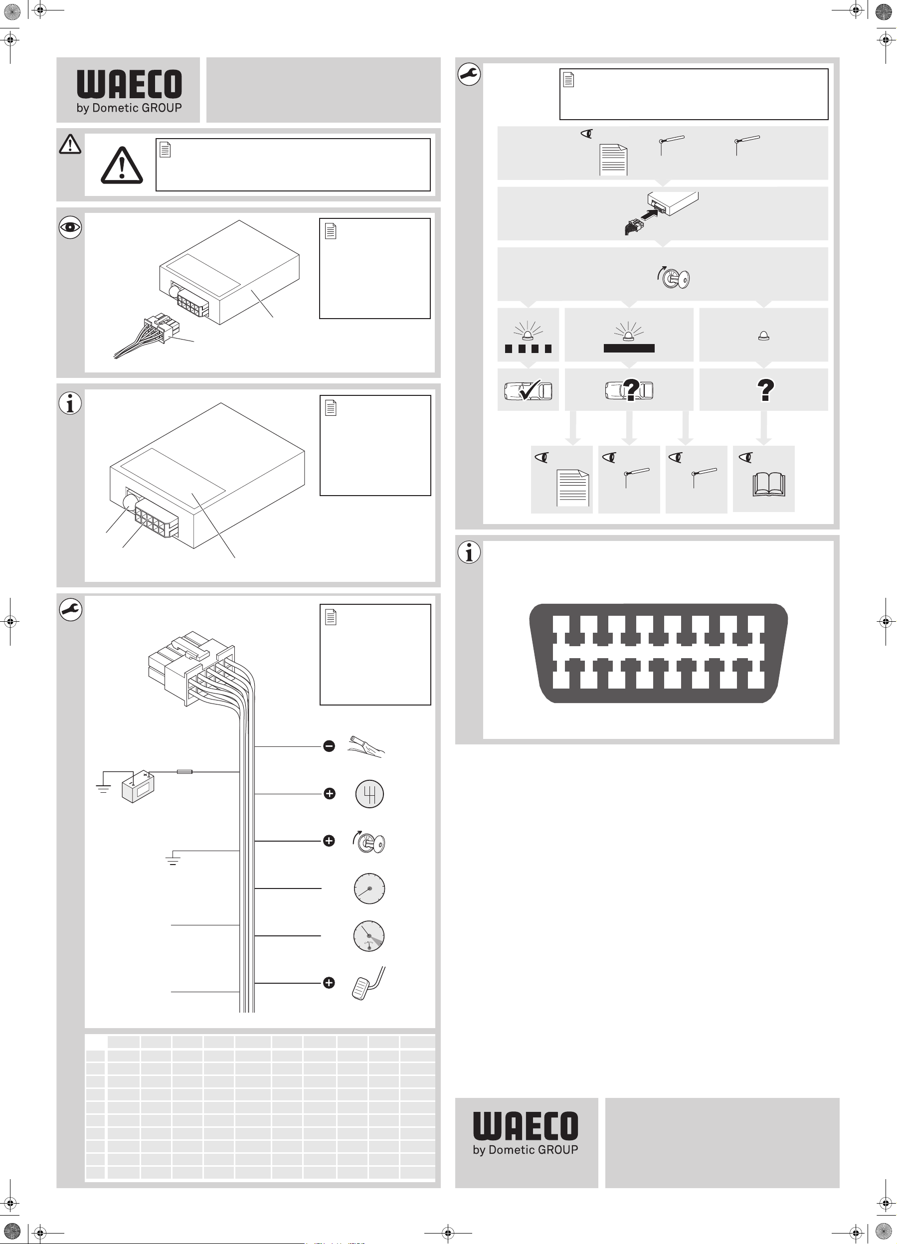
DE EN FR ES IT NL DA SV NO FI
bl Blau Blue Bleu Azul Blu Blauw Blå Blå Blå Sininen
br Braun Brown Marron Marrón Marrone Bruin Brun Brun Brun Ruskea
ge Gelb Yellow Jaune Amarillo Giallo Geel Gul Gul Gul Keltainen
gn Grün Green Vert Verde Verde Groen Grøn Grön Grønn Vihreä
or Orange Orange Orange Naranja Arancione Oranje Orange Orange Oransje Oranssi
pk Pink Pink Rosa Rose Rosa Roze Lyserøde Rosa Rosa Pinkki
rt Rot Red Rouge Rojo Rosso Rood Rød Röd Rød Punainen
sw Schwarz Black Noir Negro Nero Zwart Sort Svart Svart Musta
vt Violett Violet Violeta Lila Violetto Paars Violet Violett Fiolett Violetti
ws Weiß White Blanc Blanco Bianco Wit Hvid Vit Hvit Valkoinen
Dometic WAECO International GmbH
Hollefeldstrasse 63
D-48282 Emsdetten
www.dometic-waeco.com
3.03.06.01730F 11/2010
_IA_Can Interface.book Seite 1 Montag, 29. November 2010 5:02 17
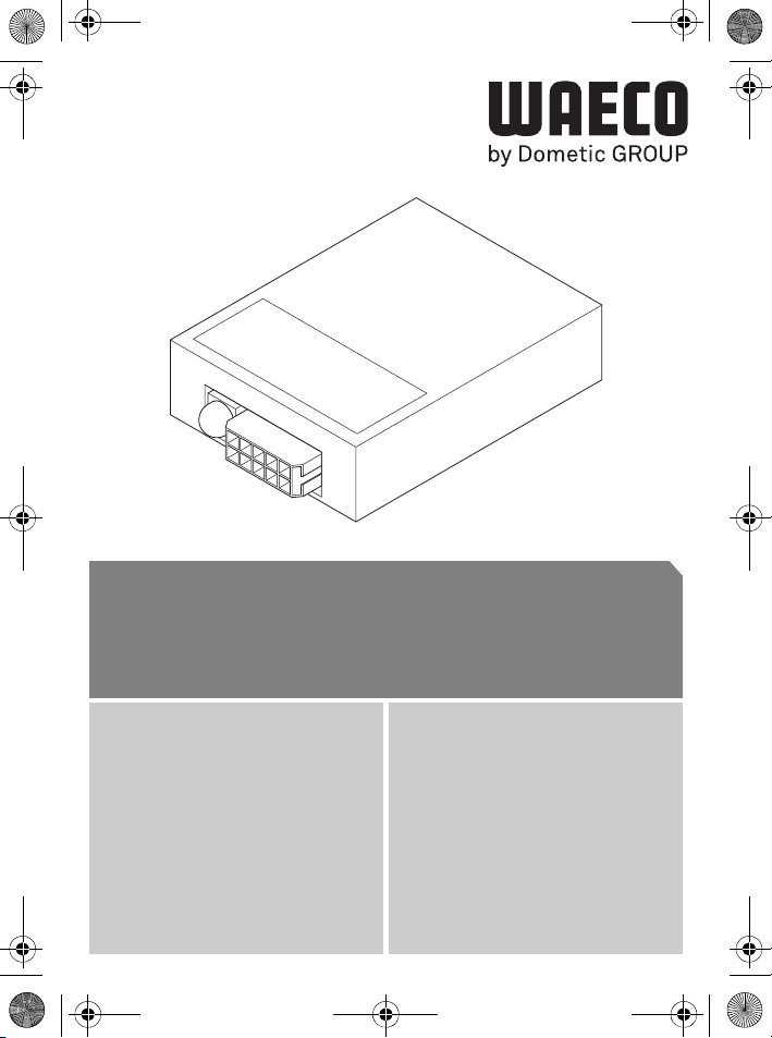
MagicSpeed CBI 150
DE 2 CAN-Bus Interface
Montage- und Bedienungsanleitung
EN 7 CAN bus interface
Installation and Operating Manual
FR 12 Interface de bus CAN
Instructions de montage et de service
ES 17 Interfaz Bus CAN
Instrucciones de montaje y de uso
IT 22 CAN-Bus Interface
Istruzioni di montaggio e d’uso
NL 27 CAN-bus interface
Montagehandleiding en gebruiksaanwijzing
DA 32 CAN-bus-interface
Monterings- og betjeningsvejledning
SV 37 CAN-bus gränssnitt
Monterings- och bruksanvisning
NO 42 CAN-bus-grensesnitt
Monterings- og bruksanvisning
FI 47 CAN-väyläliittymä
Asennus- ja käyttöohje

_IA_Can Interface.book Seite 2 Montag, 29. November 2010 5:02 17
Sicherheits- und Einbauhinweise MagicSpeed CBI 150
Bitte lesen Sie diese Anleitung vor Einbau und Inbetriebnahme sorgfältig
durch und bewahren Sie sie auf. Geben Sie sie im Falle einer Weitergabe des
Systems an den Nutzer weiter.
Inhaltsverzeichnis
1 Sicherheits- und Einbauhinweise . . . . . . . . . . . . . . . . . . . . . . . . . . . . . . . . . 2
2 Lieferumfang. . . . . . . . . . . . . . . . . . . . . . . . . . . . . . . . . . . . . . . . . . . . . . . . . 3
3 Bestimmungsgemäßer Gebrauch. . . . . . . . . . . . . . . . . . . . . . . . . . . . . . . . . 3
4 Bedienelemente . . . . . . . . . . . . . . . . . . . . . . . . . . . . . . . . . . . . . . . . . . . . . . 3
5 CAN-Bus Interface . . . . . . . . . . . . . . . . . . . . . . . . . . . . . . . . . . . . . . . . . . . . 4
6 CAN-Bus Interface anschließen . . . . . . . . . . . . . . . . . . . . . . . . . . . . . . . . . . 4
7 Gewährleistung. . . . . . . . . . . . . . . . . . . . . . . . . . . . . . . . . . . . . . . . . . . . . . . 5
8 Entsorgung . . . . . . . . . . . . . . . . . . . . . . . . . . . . . . . . . . . . . . . . . . . . . . . . . . 5
9 Technische Daten. . . . . . . . . . . . . . . . . . . . . . . . . . . . . . . . . . . . . . . . . . . . . 6
1 Sicherheits- und Einbauhinweise
Siehe Abb. 1
Die folgenden Texte ergänzen die Abbildungen auf dem Beiblatt lediglich. Sie
alleine sind keine vollständigen Einbau- und Bedienhinweise! Bitte beachten
Sie unbedingt die Abbildungen auf dem Beiblatt!
Beachten Sie die vom Fahrzeughersteller und vom Kfz-Handwerk vorgeschriebenen Sicherheitshinweise und Auflagen!
Der Hersteller übernimmt keine Haftung für Schäden aufgrund folgender Punkte:
z Beschädigungen am Produkt durch mechanische Einflüsse
z Veränderungen am Produkt ohne ausdrückliche Genehmigung vom Hersteller
z Verwendung für andere als die in der Anleitung beschriebenen Zwecke
z Beachten Sie die geltenden gesetzlichen Vorschriften.
z Installieren Sie das System im Fahrzeuginnenraum.
A
z Befestigen Sie das System so, dass sie sich unter keinen Umständen
(scharfes Abbremsen, Verkehrsunfall) lösen und zu Verletzungen der
Fahrzeuginsassen führen können.
z Montieren Sie das System nicht im Wirkungsbereich eines Airbags.
Sonst besteht Verletzungsgefahr, wenn der Airbag auslöst.
z Halten Sie einen ausreichenden Abstand zu starken Wärmequellen ein.
z Die Steuerelektronik darf keiner Feuchtigkeit ausgesetzt sein
z Der Anschluss des Geräts an sonstige, von den Vorgaben abweichende
Spannungen kann zu Gefahrsituationen führen.
2
_IA_Can Interface.book Seite 3 Montag, 29. November 2010 5:02 17
MagicSpeed CBI 150 Lieferumfang
z Nach einer Aktualisierung des Datenprotokolls durch den Fahrzeug-
hersteller funktioniert das Gerät eventuell nicht länger vorschriftsgemäß.
2 Lieferumfang
Siehe Abb. 2
Nr. Menge Bezeichnung Artikel-Nr.
1 1 CAN-Bus Interface 9101400060
2 1 Anschlusskabel
– 1 Fahrzeugliste
3 Bestimmungsgemäßer Gebrauch
MagicSpeed CBI 150 (Artikel-Nr. 9101400060) ist ein Interface zur Umwandlung digitaler CAN-Bus Signale in analoge Signale. CBI 150 dekodiert die Digitalsignale der
Bordelektrik eines Fahrzeugs und liefert an den Ausgängen Analogsignale.
MagicSpeed CBI 150 ist zum Einbau in Pkw mit CAN-Bus-Schnittstelle ausgelegt.
4 Bedienelemente
Siehe Abb. 3
Nr. Bezeichnung
1 Status-LED
2 10-polige Buchse
3 Software-Version des Moduls
3

_IA_Can Interface.book Seite 4 Montag, 29. November 2010 5:02 17
CAN-Bus Interface MagicSpeed CBI 150
5 CAN-Bus Interface
Siehe Abb. 4
Nr. Bezeichnung
1 Pinkfarbene Ader: Signal „Handbremse betätigt“
2 Braune Ader: Signal „Rückwärtsgang eingelegt“
3 Violette Ader: Signal „Zündung eingeschaltet“
4 Grüne Ader: Geschwindigkeitsignal des Tachometers
5 Gelbe Ader: Drehzahlsignal
6 Orange Ader: Signal „Kupplung getreten“
7 Weiße Ader: Anschluss an CAN High
8 Blaue Ader: Anschluss an CAN Low
9 Schwarze Ader: Anschluss an Masse
10 Rote Ader: Anschluss an eine Leitung, die mit höchstens 5 A abgesichert ist
6 CAN-Bus Interface anschließen
HINWEIS
Die Belegung des OBD-II-Steckers finden Sie in Abb. 6.
I
Ergänzung zu Abb. 5
➤ Stellen Sie vor dem Einbau sicher, dass die von Ihnen benötigten Ausgangs-
signale für Ihr Fahrzeug von CBI150 zur Verfügung gestellt werden können.
Eine detaillierte Fahrzeugliste finden Sie unter:
htp://www.dometic-waeco.de/cbi150.
HINWEIS
Verbinden Sie die Leitungen nur mit den CAN-Bus-Leitungen im Fahrzeug,
I
die in der Fahrzeugliste angegebenen sind.
➤ Verbinden Sie die weiße und die blaue Ader mit den CAN-Bus-Leitungen, wie in
der Fahrzeugliste beschrieben.
➤ Stecken Sie den Stecker des Anschlusskabels in die Buchse am CAN-Bus In-
terface.
➤ Schalten Sie die Zündung ein.
✓ Die Status-LED zeigt den Zustand des Systems an.
4

_IA_Can Interface.book Seite 5 Montag, 29. November 2010 5:02 17
MagicSpeed CBI 150 Gewährleistung
Status-LED blinkt: das Fahrzeug wurde erkannt
Sie können das CAN-Bus Interface verwenden.
Sie können die Funktionalität wie folgt prüfen:
➤ Schalten Sie die Zündung und alle Verbraucher aus.
➤ Ziehen Sie den Zündschlüssel ab.
➤ Schließen und verriegeln Sie alle Fahrzeugtüren.
✓ Nach einer Verzögerungszeit (fahrzeugabhängig) erlischt die Status-LED.
Status-LED leuchtet: das Fahrzeug wurde nicht erkannt
➤ Prüfen Sie, ob:
– das gewünschte Fahrzeug in der Fahrzeugliste enthalten ist
– die CAN-Bus-Leitungen korrekt angeschlossen sind
– die CAN-Bus-Leitungen an der richtigen Stelle im Fahrzeug (siehe Fahrzeug-
liste) abgegriffen werden
Status-LED ist ausgeschaltet
➤ Prüfen Sie, ob:
– die Spannungsversorgung 12 V beträgt
– die CAN-Bus-Leitungen korrekt angeschlossen sind
7 Gewährleistung
Es gilt die gesetzliche Gewährleistungsfrist. Sollte das Produkt defekt sein, wenden
Sie sich bitte an die Niederlassung des Herstellers in Ihrem Land (Adressen siehe
Rückseite der Anleitung) oder an Ihren Fachhändler.
Zur Reparatur- bzw. Gewährleistungsbearbeitung müssen Sie folgendes einschicken:
z defekte Komponenten,
z eine Kopie der Rechnung mit Kaufdatum,
z einen Reklamationsgrund oder eine Fehlerbeschreibung.
8 Entsorgung
➤ Geben Sie das Verpackungsmaterial möglichst in den entsprechenden
Recycling-Müll.
Wenn Sie das Produkt endgültig außer Betrieb nehmen, informieren Sie
sich bitte beim nächsten Recyclingcenter oder bei Ihrem Fachhändler über
M
die zutreffenden Entsorgungsvorschriften.
5
_IA_Can Interface.book Seite 6 Montag, 29. November 2010 5:02 17
Technische Daten MagicSpeed CBI 150
9 Technische Daten
MagicSpeed CBI 150
Artikel-Nr.: 9101400060
Anschlussspannung: 12 V
Stromaufnahme (bei 12 V): maximal 0,5 A
Ruhestromaufnahme: max. 1 mA
Betriebstemperatur: –40 °C bis + 85 °C
Zulassung:
11
Ausführungen, dem technischen Fortschritt dienende Änderungen und Liefermöglichkeiten vorbehalten.
6

_IA_Can Interface.book Seite 7 Montag, 29. November 2010 5:02 17
MagicSpeed CBI 150 Safety and installation instructions
Please read this manual carefully before installing and starting up, and store it
in a safe place. If you pass on the system to another person, hand over this instruction manual along with it.
Table of contents
1 Safety and installation instructions . . . . . . . . . . . . . . . . . . . . . . . . . . . . . . . . 7
2 Scope of delivery . . . . . . . . . . . . . . . . . . . . . . . . . . . . . . . . . . . . . . . . . . . . . 8
3 Intended use. . . . . . . . . . . . . . . . . . . . . . . . . . . . . . . . . . . . . . . . . . . . . . . . . 8
4 Control elements. . . . . . . . . . . . . . . . . . . . . . . . . . . . . . . . . . . . . . . . . . . . . . 8
5 CAN bus interface. . . . . . . . . . . . . . . . . . . . . . . . . . . . . . . . . . . . . . . . . . . . . 9
6 Connecting the CAN bus interface . . . . . . . . . . . . . . . . . . . . . . . . . . . . . . . . 9
7 Guarantee. . . . . . . . . . . . . . . . . . . . . . . . . . . . . . . . . . . . . . . . . . . . . . . . . . 10
8 Disposal . . . . . . . . . . . . . . . . . . . . . . . . . . . . . . . . . . . . . . . . . . . . . . . . . . . 10
9 Technical data . . . . . . . . . . . . . . . . . . . . . . . . . . . . . . . . . . . . . . . . . . . . . . 11
1 Safety and installation instructions
See Abb. 1
The following texts are only a supplement to the illustrations on the supple-
mentary sheet. They do not contain the full installation and operating instructions. Please observe the illustrations on the supplementary sheet.
Please observe the prescribed safety instructions and stipulations from the vehicle manufacturer and service workshops.
The manufacturer will not be held liable for claims for damage resulting from the following:
z Damage to the product resulting from mechanical influences and excess voltage
z Alterations to the product without express permission from the manufacturer
z Use for purposes other than those described in the operating manual
z Observe the applicable legal regulations.
z Install the system in the vehicle interior.
A
z Secure the system in such a way that it cannot become loose under any
circumstances (sudden braking, accidents) and cause injuries to the
occupants of the vehicle.
z Do not fit the system where an airbag may open. This could cause injury
if the airbag deploys.
z Maintain a sufficient interval to intense sources of heat.
z Do not expose the control electronics to moisture.
7
_IA_Can Interface.book Seite 8 Montag, 29. November 2010 5:02 17
Scope of delivery MagicSpeed CBI 150
z Connecting the device to other operating voltages than those specified
may cause hazardous situations.
z After a data protocol update by the vehicle manufacturer, the device may
no longer function according to the instructions.
2 Scope of delivery
See Abb. 2
No. Quantity Designation Item no.
1 1 CAN bus interface 9101400060
2 1 Connection cable
– 1 Vehicle list
3 Intended use
MagicSpeed CBI 150 (item no. 9101400060) is an interface for converting digital
CAN bus signals into analogue signals. CBI 150 decodes the digital signals from the
on-board vehicle electronics and transmits analogue signals to the outputs.
MagicSpeed CBI 150 is designed for installation in passenger vehicles with a CAN
bus port.
4 Control elements
See Abb. 3
No. Designation
1 Status LED
2 10-pin socket
3 Software version for the module
8
_IA_Can Interface.book Seite 9 Montag, 29. November 2010 5:02 17
MagicSpeed CBI 150 CAN bus interface
5 CAN bus interface
See Abb. 4
No. Designation
1 Pink cable: “Handbrake applied” signal
2 Brown cable: “Reverse gear engaged” signal
3 Violet cable: “Ignition switched on” signal
4 Green cable: Speedometer signal
5 Yellow cable: Engine speed signal
6 Orange cable: “Clutch applied” signal
7 White cable: Connection to CAN High
8 Blue cable: Connection to CAN Low
9 Black cable: Connection to earth
10 Red cable: Connection to a cable which is protected with max. 5 A
6 Connecting the CAN bus interface
NOTE
The configuration of the OBD-II plug can be found in Abb. 6.
I
Supplementary to Abb. 5
➤ Before installation, make sure that the output signals you need for your vehicle
are available from CBI150.
You can find a detailed vehicle list at:
htp://www.dometic-waeco.de/cbi150.
NOTE
Only connect the cables to the CAN bus cables in the vehicle which are
I
specified in the vehicle list.
➤ Connect the white and the blue cables with the CAN bus cables as described in
the vehicle list.
➤ Insert the plug of the connection cable into the socket of the CAN bus interface.
➤ Switch on the ignition.
✓ The status LED indicates the system status.
9
_IA_Can Interface.book Seite 10 Montag, 29. November 2010 5:02 17
Guarantee MagicSpeed CBI 150
Status LED flashes: the vehicle type has been recognised
You can use the CAN bus interface.
You can test the functions as follows:
➤ Switch the ignition and all the consumer units off.
➤ Remove the ignition key.
➤ Close and lock all the vehicle doors.
✓ The status LED goes out after a delay time (depending on the model).
Status LED is lit: the vehicle type is not recognised
➤ Check whether:
– the vehicle type is included in the vehicle list.
– the CAN bus cables are correctly connected.
– the CAN bus cables are detected in the right position in the vehicle (see ve-
hicle list)
Status LED is switched off
➤ Check whether:
– the power supply is 12 V
– the CAN bus cables are correctly connected.
7Guarantee
The statutory warranty period applies. If the product is defective, please contact the
manufacturer's branch in your country (see the back of the instruction manual for the
addresses) or your retailer.
For repair and guarantee processing, please send the following items:
z Defect components
z A copy of the receipt with purchasing date
z A reason for the claim or description of the fault
8Disposal
➤ Place the packaging material in the appropriate recycling waste bins wherever
possible.
If you wish to finally dispose of the product, ask your local recycling centre
or specialist dealer for details about how to do this in accordance with the
M
applicable disposal regulations.
10
_IA_Can Interface.book Seite 11 Montag, 29. November 2010 5:02 17
MagicSpeed CBI 150 Technical data
9 Technical data
MagicSpeed CBI 150
Item no.: 9101400060
Voltage: 12 V
Power consumption (at 12 V): maximum 0.5 A
Quiescent current consumption: max. 1 mA
Operating temperature: –40 °C to + 85 °C
Certification:
11
Different versions, technical modifications and delivery options reserved.
11

_IA_Can Interface.book Seite 12 Montag, 29. November 2010 5:02 17
Consignes de sécurité et instructions de montage MagicSpeed CBI 150
Veuillez lire ce manuel avec attention avant le montage et la mise en service,
puis le conserver. En cas de revente du système, veuillez le transmettre au
nouvel acquéreur.
Table des matières
1 Consignes de sécurité et instructions de montage . . . . . . . . . . . . . . . . . . . 12
2 Contenu de la livraison . . . . . . . . . . . . . . . . . . . . . . . . . . . . . . . . . . . . . . . . 13
3 Usage conforme . . . . . . . . . . . . . . . . . . . . . . . . . . . . . . . . . . . . . . . . . . . . . 13
4 Eléments de commande . . . . . . . . . . . . . . . . . . . . . . . . . . . . . . . . . . . . . . . 13
5 Interface de bus CAN . . . . . . . . . . . . . . . . . . . . . . . . . . . . . . . . . . . . . . . . . 14
6 Raccordement interface de bus CAN . . . . . . . . . . . . . . . . . . . . . . . . . . . . . 14
7 Garantie . . . . . . . . . . . . . . . . . . . . . . . . . . . . . . . . . . . . . . . . . . . . . . . . . . . 15
8 Elimination . . . . . . . . . . . . . . . . . . . . . . . . . . . . . . . . . . . . . . . . . . . . . . . . . 15
9 Caractéristiques techniques . . . . . . . . . . . . . . . . . . . . . . . . . . . . . . . . . . . . 16
1 Consignes de sécurité et instructions de montage
Voir Abb. 1
Les textes suivants ne font que compléter les illustrations en annexe. Il ne
s'agit pas d'instructions complètes de montage et d'utilisation ! Veuillez impérativement respecter les illustrations en annexe !
Respectez les consignes de sécurité et autres prescriptions imposées par le
fabricant du véhicule et par les professionnels de l'automobile !
Le fabricant décline toute responsabilité en cas de dommages causés par :
z des influences mécaniques et des surtensions ayant endommagé le matériel
z des modifications apportées au produit sans autorisation explicite de la part du
fabricant
z une utilisation différente de celle décrite dans la notice
z Respectez les consignes légales en vigueur.
z Installez le système dans l'habitacle du véhicule.
A
z Fixez le système de manière à ce qu’il ne puisse en aucun cas (freinage
violent, accident) se détacher et blesser les occupants du véhicule.
z N'installez pas le système dans le champ d'action d'un airbag. Il risque-
rait de blesser les passagers en cas d'enclenchement de l'airbag.
z Veillez à respecter un écart suffisant par rapport aux fortes sources de
chaleur.
12
_IA_Can Interface.book Seite 13 Montag, 29. November 2010 5:02 17
MagicSpeed CBI 150 Contenu de la livraison
z Veillez à ce que l'électronique de commande ne soit pas exposée à l'hu-
midité.
z Le raccordement de l'appareil à des tensions ne correspondant pas à
celles indiquées peut entraîner des situations dangereuses.
z En cas d'actualisation du protocole de données par le constructeur du
véhicule, il est possible que l'appareil ne fonctionne plus de manière conforme.
2 Contenu de la livraison
Voir Abb. 2
Nº Quantité Désignation N° d'article
1 1 Interface de bus CAN 9101400060
2 1 Câble de raccordement
– 1 Liste de véhicules
3 Usage conforme
MagicSpeed CBI 150 (n° d'article 9101400060) est une interface permettant de
transformer les signaux numériques de bus CAN en signaux analogiques. CBI 150
décode les signaux numériques de l'électronique de bord d'un véhicule et transmet
des signaux analogiques aux sorties.
MagicSpeed CBI 150 est conçu pour être monté dans des véhicules de tourisme à
interface de bus CAN.
4 Eléments de commande
Voir Abb. 3
Nº Désignation
1 LED d'état
2 Prise femelle à 10 pôles
3 Version logicielle du module
13
_IA_Can Interface.book Seite 14 Montag, 29. November 2010 5:02 17
Interface de bus CAN MagicSpeed CBI 150
5 Interface de bus CAN
Voir Abb. 4
Nº Désignation
1 Fil rose : signal « Frein à main actionné »
2 Fil marron : signal « Marche arrière enclenchée »
3 Fil violet : signal « Contact allumé »
4 Fil vert : signal de vitesse du compteur de vitesse
5 Fil jaune : signal du régime
6 Fil orange : signal « Pédale d'embrayage actionnée »
7 Fil blanc : raccordement à CAN High
8 Fil bleu : raccordement à CAN Low
9 Fil noir : raccordement à la masse
10 Fil rouge : raccordement à un câble dont le fusible de protection est au maximum de
5A
6 Raccordement interface de bus CAN
REMARQUE
Vous trouverez l'affectation du connecteur OBD-II à la Abb. 6.
I
Complément de Abb. 5
➤ Avant le montage, assurez-vous que CBI150 peut vous fournir les signaux de
sortie dont vous avez besoin pour votre véhicule.
Vous trouverez une liste détaillée des véhicules sur :
htp://www.dometic-waeco.de/cbi150.
REMARQUE
Raccordez les câbles uniquement aux câbles de bus CAN du véhicule indi-
I
qués dans la liste des véhicules.
➤ Raccordez les câbles blanc et bleu aux câbles de bus CAN comme indiqué dans
la liste des véhicules.
➤ Enfoncez le connecteur du câble de raccordement dans la douille de l'interface
de bus CAN.
➤ Mettez le contact.
✓ La LED indique l'état du système.
14
_IA_Can Interface.book Seite 15 Montag, 29. November 2010 5:02 17
MagicSpeed CBI 150 Garantie
La LED d'état clignote : le véhicule a été reconnu
Vous pouvez utiliser l'interface de bus CAN.
Vous pouvez vérifier le fonctionnement de la manière suivante :
➤ Eteignez l'allumage et tous les consommateurs de courant.
➤ Retirez la clé de contact.
➤ Fermez et verrouillez toutes les portières du véhicule.
✓ Après un temps de délai (selon le véhicule), la LED d'état s'éteint.
La LED d'état s'allume : le véhicule n'a pas été reconnu
➤ Vérifiez si :
– le véhicule souhaité figure sur la liste des véhicules
– les lignes du bus CAN sont correctement raccordées
– les lignes du bus CAN sont captées au bon endroit du véhicule (voir liste des
véhicules)
La LED d'état est éteinte
➤ Vérifiez si :
– l'alimentation électrique est bien de 12 V
– les lignes du bus CAN sont correctement raccordées
7Garantie
Le délai légal de garantie s'applique. Si le produit s'avérait défectueux, veuillez vous
adresser à la filiale du fabricant située dans votre pays (voir adresses au verso du
présent manuel) ou à votre revendeur spécialisé.
Pour toute réparation ou autre prestation de garantie, veuillez joindre à l'appareil les
documents suivants :
z composants défectueux,
z une copie de la facture avec la date d'achat,
z le motif de la réclamation ou une description du dysfonctionnement.
8 Elimination
➤ Jetez les emballages dans les conteneurs de déchets recyclables prévus à cet
effet.
Lorsque vous mettrez votre produit définitivement hors service, informezvous auprès du centre de recyclage le plus proche ou auprès de votre
M
revendeur spécialisé sur les prescriptions relatives au retraitement des
déchets.
15
 Loading...