

Page 1
VT50WiFi
ENDEFR
ESPTIT
NL
DA
SV
NO
FIRUPL
SKCSHU
DRIVING SUPPORT
PERFECTVIEW
WiFi-achteruitrijvideosysteem met
smartphone-app
Montagehandleiding en
gebruiksaanwijzing . . . . . . . . . . . . . . . . . 74
WiFi-bakkamerasystem med
smartphone-app
Monterings- og betjeningsvejledning . . 85
WiFi-backvideosystem med
mobiltelefon-app
Monterings- och bruksanvisning. . . . . . . 95
WiFi rear view system with
smartphone app
Installation and Operating Manual . . . . . . 8
WiFi-Rückfahrvideosystem mit
Smartphone-App
Montage- und Bedienungsanleitung . . . 19
Système vidéo de recul WiFi avec
application smartphone
Instructions de montage
et de service . . . . . . . . . . . . . . . . . . . . . . . 30
Sistema de vídeo para marcha
atrás con app para smartphone
Instrucciones de montaje y de uso . . . . . 41
Sistema de vídeo de marcha-atrás
WiFi com aplicação para
smartphone
Instruções de montagem e manual de
instruções . . . . . . . . . . . . . . . . . . . . . . . . . 52
Sistema video per retromarcia
WiFi con app per smartphone
Istruzioni di montaggio e d’uso . . . . . . . .63
WiFi-ryggevideosystem med
smarttelefon-app
Monterings- og bruksanvisning . . . . . . 105
WiFi-peruutusvideojärjestelmä
älypuhelinsovelluksella
Asennus- ja käyttöohje. . . . . . . . . . . . . . .116
Видеосистема заднего обзора с
поддержкой WiFi и мобильным
приложением
Инструкция по монтажу
и эксплуатации. . . . . . . . . . . . . . . . . . . . 127
System wideo cofania WiFi
z aplikacją na smartfona
Instrukcja montażu i obsługi . . . . . . . . . 138
WiFi cúvací videosystém
s aplikáciou pre smartfóny
Návod na montáž a uvedenie
do prevádzky . . . . . . . . . . . . . . . . . . . . . 149
WiFi kamerový systém pro couvání
s aplikací pro smartphony
Návod k montáži a obsluze . . . . . . . . . . 160
WiFi tolató-videorendszer
okostelefon applikációval
Szerelési és használati útmutató . . . . . . .171
Page 2

Page 3
VT50WiFi
1
1
2
5
4
3
2
3
Page 4
VT50WiFi
1
2
3
4
9
6 8
5
7
10
11
3
4
Page 5
VT50WiFi
180°
1
2
4
180°
1
2
5
5
Page 6
VT50WiFi
6
1.
2.
7
8
6
Page 7

VT50WiFi
2.
1.
1
3
2
9
7
Page 8

Explanation of symbols VT50WiFi
EN
Please read this instruction manual carefully before installation and first use, and store
it in a safe place. If you pass on the product to another person, hand over this instruction manual along with it.
Table of contents
1 Explanation of symbols. . . . . . . . . . . . . . . . . . . . . . . . . . . . . . . . . . . . . . . . . . . . . . . . . . . . . . .8
2 Safety and installation instructions . . . . . . . . . . . . . . . . . . . . . . . . . . . . . . . . . . . . . . . . . . . . . .9
3 Scope of delivery . . . . . . . . . . . . . . . . . . . . . . . . . . . . . . . . . . . . . . . . . . . . . . . . . . . . . . . . . . 11
4 Intended use . . . . . . . . . . . . . . . . . . . . . . . . . . . . . . . . . . . . . . . . . . . . . . . . . . . . . . . . . . . . . . 11
5 Technical description . . . . . . . . . . . . . . . . . . . . . . . . . . . . . . . . . . . . . . . . . . . . . . . . . . . . . . . 11
6 Mounting the camera and transmitter . . . . . . . . . . . . . . . . . . . . . . . . . . . . . . . . . . . . . . . . . . 12
7 Connecting the transmitter electrically . . . . . . . . . . . . . . . . . . . . . . . . . . . . . . . . . . . . . . . . . 14
8 Using VT50WiFi . . . . . . . . . . . . . . . . . . . . . . . . . . . . . . . . . . . . . . . . . . . . . . . . . . . . . . . . . . . 16
9 Troubleshooting . . . . . . . . . . . . . . . . . . . . . . . . . . . . . . . . . . . . . . . . . . . . . . . . . . . . . . . . . . . 16
10 Warranty . . . . . . . . . . . . . . . . . . . . . . . . . . . . . . . . . . . . . . . . . . . . . . . . . . . . . . . . . . . . . . . . . 17
11 Disposal. . . . . . . . . . . . . . . . . . . . . . . . . . . . . . . . . . . . . . . . . . . . . . . . . . . . . . . . . . . . . . . . . . 17
12 Technical data. . . . . . . . . . . . . . . . . . . . . . . . . . . . . . . . . . . . . . . . . . . . . . . . . . . . . . . . . . . . . 18
1 Explanation of symbols
WARNING!
!
!
A
Safety instruction: Failure to observe this instruction can cause fatal or serious injury.
CAUTION!
Safety instruction: Failure to observe this instruction can lead to injury.
NOTICE!
Failure to observe this instruction can cause material damage and impair the function
of the product.
NOTE
I
8
Supplementary information for operating the product.
Page 9

VT50WiFi Safety and installation instructions
EN
2 Safety and installation instructions
The manufacturer accepts no liability for damage in the following cases:
• Damage to the product resulting from mechanical influences and excess voltage
• Alterations to the product without express permission from the manufacturer
• Use for purposes other than those described in the operating manual
Please observe the prescribed safety instructions and stipulations from the vehicle
manufacturer and service workshops.
WARNING!
Inadequate supply cable connections could result in short circuits, which could have as
!
a consequence that:
• Cable fires occur
• The airbag is triggered
• Electronic control devices are damaged
• Electric functions fail (indicators, brake light, horn, ignition, lights)
NOTICE!
To prevent the risk of short circuits, always disconnect the negative terminal of the
A
Please observe the following instructions:
• When working on the following cables, only use insulated cable lugs, plugs and flat push-on
receptacles:
– 30 (direct supply from positive battery terminal)
–15 (connected positive terminal, behind the battery)
– 31 (return line from the battery, earth)
– L (indicator lights left)
– R (indicator lights right)
Do not use terminal strips.
• Use a crimping tool to connect the cables.
• When connecting to cable 31 (earth), screw the cable
– to the vehicle's earth bolt with a cable lug and a gear disc or
– to the sheet-metal bodywork with a cable lug and a self-tapping screw.
vehicle's electrical system before working on it.
If the vehicle has an additional battery, its negative terminal should also be disconnected.
Ensure that there is a good earth connection.
9
Page 10

Safety and installation instructions VT50WiFi
EN
If you disconnect the negative terminal of the battery, all data stored in the volatile memories will
be lost.
• The following data must be set again, depending on the vehicle equipment options:
–Radio code
– Vehicle clock
–Timer
– On-board computer
– Seat position
You can find instructions for making these settings in the appropriate operating instructions.
Observe the following installation instructions:
CAUTION!
!
A
Observe the following instructions when working with electrical parts:
A
• Secure the parts installed in the vehicle in such a way that they cannot become loose
under any circumstances (sudden braking, accidents) and cause injuries to the
occupants of the vehicle.
• Secure any parts of the system covered by the bodywork in such a manner that they
cannot be come loose or damage other parts and cables or impair vehicle functions
(steering, pedals, etc).
• Always follow the safety instructions of the vehicle manufacturer.
Some work (e.g. on retention systems such as the AIRBAG etc.) may only be
performed by qualified specialists.
NOTICE!
• To prevent damage when drilling, make sure there is sufficient space on the other
side for the drill head to come out.
• Deburr all drill holes and treat them with a rust-protection agent.
NOTICE!
• When testing the voltage in electrical cables, only use a diode test lamp or a
voltmeter.
Test lamps with an illuminant take up voltages which are too high and which can
damage the vehicle's electronic system.
• When making electrical connections, ensure that:
– they are not kinked or twisted
– they do not rub on edges
– they are not laid in sharp edged ducts without protection.
• Insulate all connections.
• Secure the cables against mechanical wear with cable binders or insulating tape,
for example to existing cables.
10
Page 11

VT50WiFi Scope of delivery
EN
3Scope of delivery
Quantity Label
1 Camera with number plate fastening
1Transmitter
–Fastening material
1Instruction
4Intended use
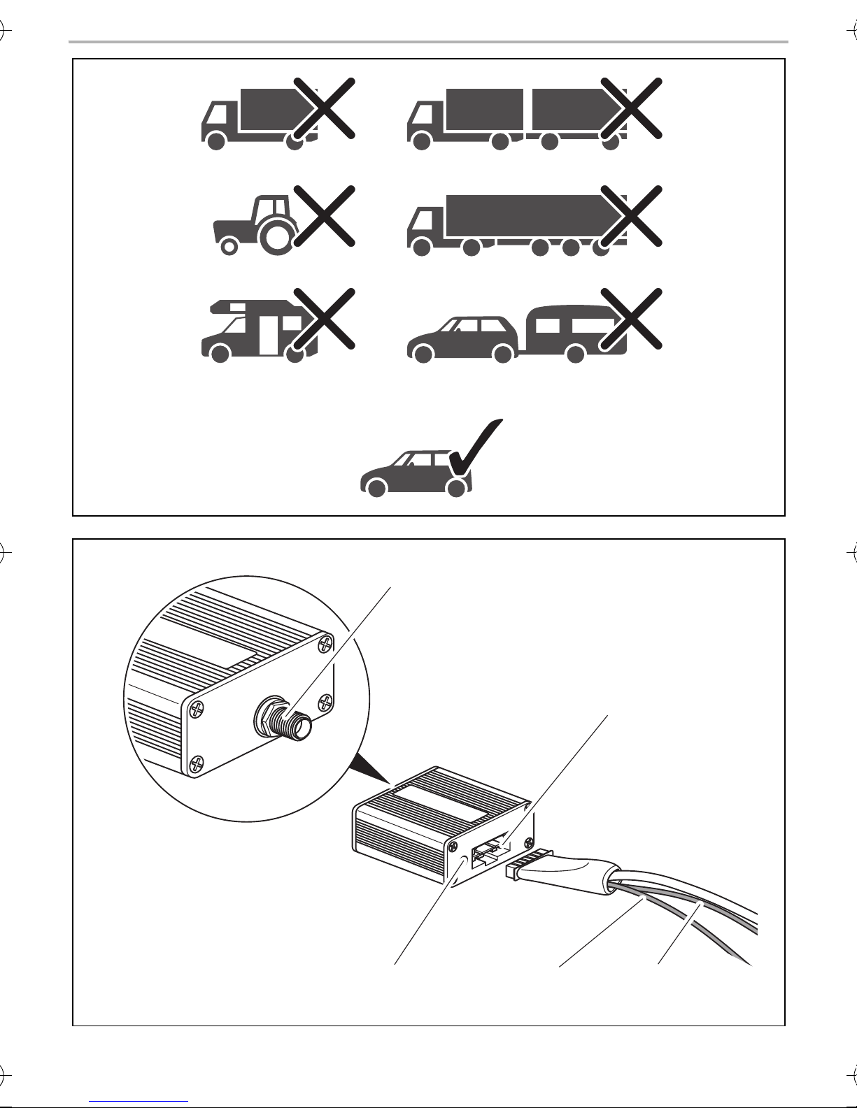
PerfectView VT50WiFi (ref. no. 9600003262) is a rear view video camera with a WiFi transmitter.
The transmitter wirelessly transmits the signals between the rear view video camera and a smartphone or tablet with an iOS™ or Android™ operating system. PerfectView VT50WiFi is only
suitable for use on cars (fig. 1, page 3).
5 Technical description
5.1 Function description
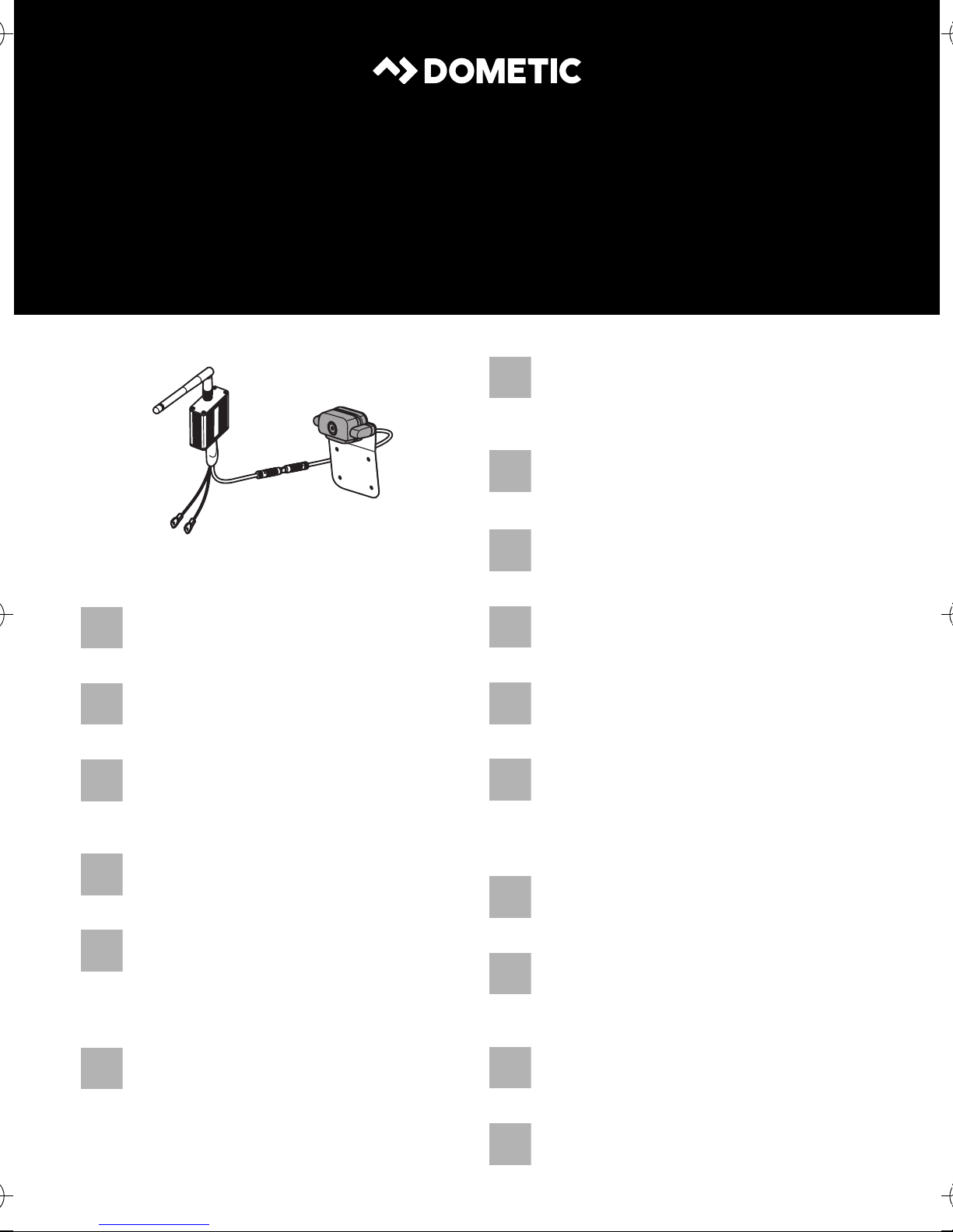
PerfectView VT50WiFi comprises a rear view video camera with a number plate fastening, a WiFi
transmitter and an app for mobile end devices such as smartphones or tablets.
The transmitter is mounted in the vehicle. It establishes a wireless radio network and transmits the
image over it to a smartphone or tablet.
The transmitter is connected to the reversing light and is also used to supply the camera with
power. The transmitter must re-establish the wireless connection every time the car is shifted into
reverse gear. This requires about six seconds.
The wireless signals are transmitted in the 2.4 GHz range.
As the system is only designed as an additional aid for reversing, it does not relieve you of the duty
to exercise due care especially when driving with a trailer.
NOTICE!
A
The transmitter sends digital data. The camera image is displayed on the monitor with
a delay of 0.2 seconds. It is therefore essential that you drive slowly.
11
Page 12

Mounting the camera and transmitter VT50WiFi
EN
5.2 Control elements
No. in
fig. 2, page 3
1 Antenna connection
2 Camera connection
3 Red cable (DC INPUT): Connection to the positive terminal (+) of the
4 Black cable (GND): Connection to the negative terminal (–) of the
5 Operating display; lights up as soon as voltage is applied
Meaning
power supply
power supply or earth terminal
6 Mounting the camera and transmitter
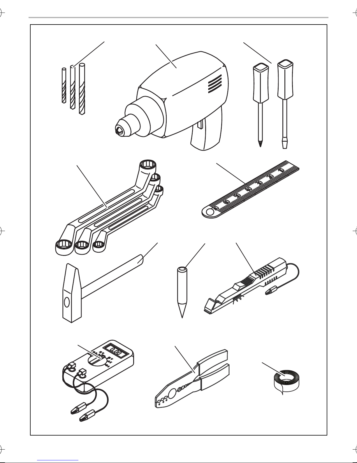
6.1 Tools required (fig. 3, page 4)
For installation and assembly you will need the following tools:
• Drill head set (1)
• Drill (2)
• Screwdriver (3)
• Set of ring or open-ended spanners (4)
• Tape measure (5)
• Hammer (6)
• Centre punch (7)
To establish and test the electrical connection, the following tools are required:
• Diode test lamp (8) or voltmeter (9)
• Crimping tool (10)
• Insulating tape (11)
• Cable bushing sleeves (optional)
To secure the camera, transmitter and the cable, you may require additional screws, cable
binders and double-sided tape.
12
Page 13

VT50WiFi Mounting the camera and transmitter
EN
6.2 Preparing the camera for installation
Observe the following mounting instructions:
• Place the camera in the centre over or under the number plate. The camera requires a free space
of 30 mm above or below the number plate.
• Fasten the camera in a way that does not cover the number plate.
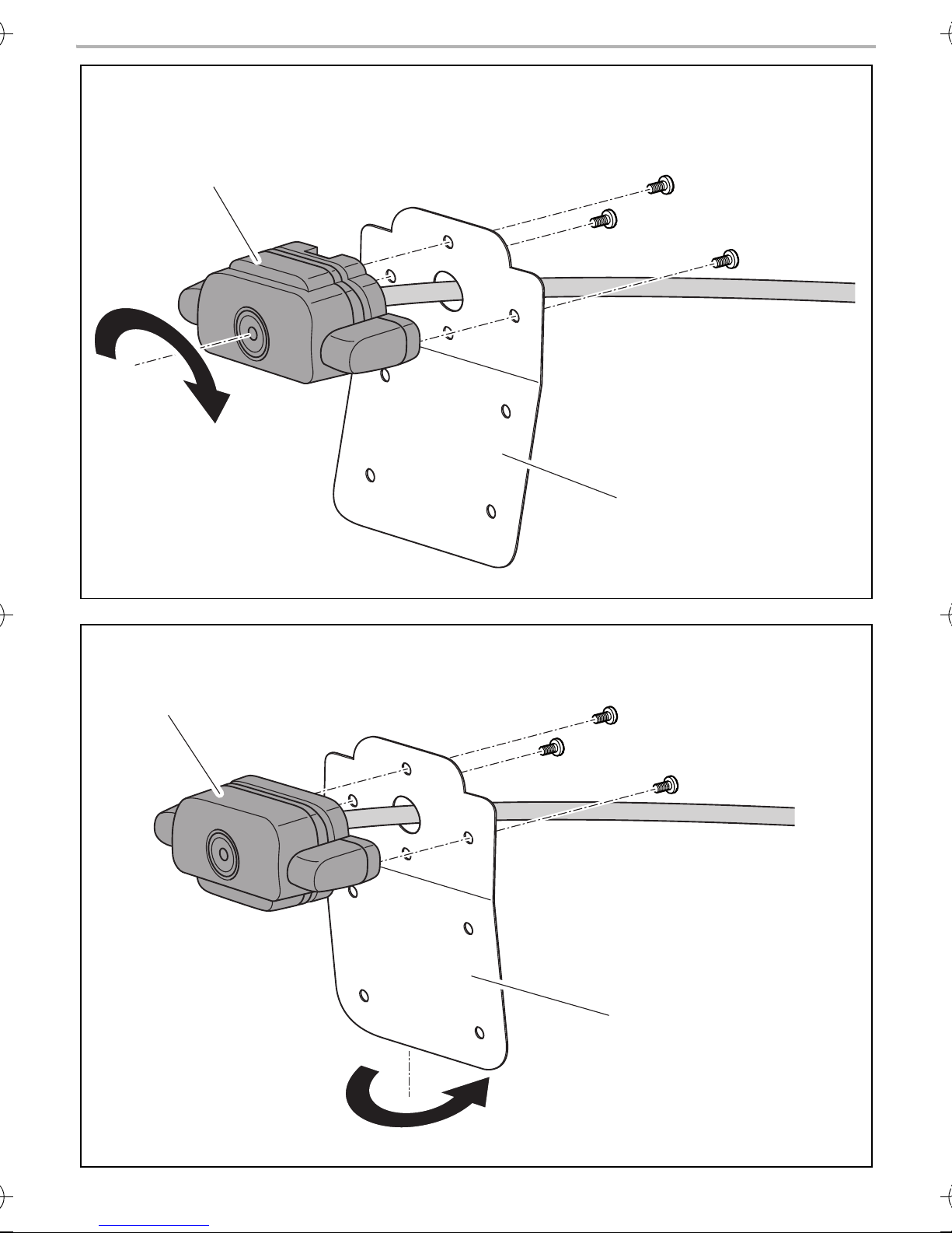
Mounting the camera under the number plate (fig. 4, page 5)
➤ Unscrew the camera (1) from the assembly plate (2).
➤ Turn the camera by 180°.
➤ Reattach the camera to the assembly plate.
Adjusting the installation position on the rear of the vehicle (fig. 5, page 5)
The camera is attached to the upper part of the assembly plate. The upper part of the assembly
plate is bent at an angle of approximately 5°. You can fit the camera to the rear of the assembly
plate to adjust the assembly position to the shape of the vehicle rear.
➤ Unscrew the camera (1) from the assembly plate (2).
➤ Turn the assembly plate by 180°.
➤ Reattach the camera to the assembly plate.
6.3 Fastening the camera
➤ Remove the rear number plate holder from the vehicle.
➤ Attach the camera assembly plate to the rear of the number plate holder with double-sided
tape.
➤ Reattach the number plate holder to the vehicle. In doing so, press the double-sided tape onto
the bodywork.
✓ The camera is now attached to the vehicle.
6.4 Preparing the transmitter for installation
CAUTION!
!
Observe the following mounting instructions:
Select the location of the transmitter so that it cannot injure the passengers in the
vehicle under any circumstances (e.g. sudden braking, road traffic accidents).
• Install the transmitter so that as few objects as possible are situated between the transmitter and
receiving device. Moving the transmitter can help if there is a poor connection.
• The installation location should be flat.
• Before drilling each hole, ensure there is sufficient space on the other side for the drill head to
emerge (fig. 6, page 6).
• Make sure you can lay the connection cable from the transmitter to the camera.
13
Page 14

Connecting the transmitter electrically VT50WiFi
EN
NOTE
I
The image is sent from the transmitter to the receiving device. To ensure flawless
functioning, you need to check whether the wireless transmission is stable before final
installation.
6.5 Attaching the transmitter
➤ Attach the transmitter temporarily to the planned installation location.
➤ Put the transmitter into operation.
➤ Activate the app on your receiving device (see chapter “Using VT50WiFi” on page 16).
If a fault occurs, e.g. there are flickering images:
➤ Adjust the location of the transmitter slightly.
➤ Retest the transmission.
If the camera image transmission is stable (no flickering images):
➤ Secure the transmitter with double-sided tape.
7 Connecting the transmitter electrically
7.1 General notes on laying cables
NOTE
I
Therefore, please observe the following instructions:
• Wherever possible, lay cables inside the vehicle, as they are better protected there than
outside.
If you do need to lay a cable outside the vehicle, ensure that it is well fastened (use additional
cable ties, insulating tape etc.).
• As far as possible, use original ducts for laying the cables, or other suitable options
such as panelling edges, ventilation grilles or dummy plugs.
If no openings are available, you must drill holes for the cables. Check beforehand
that there is sufficient space on the other side for the drill head to emerge.
• Cables and connections that are not properly installed will cause malfunctions or
damage to components. Correct installation of cables and connections ensures
lasting and trouble-free operation of the retrofitted components.
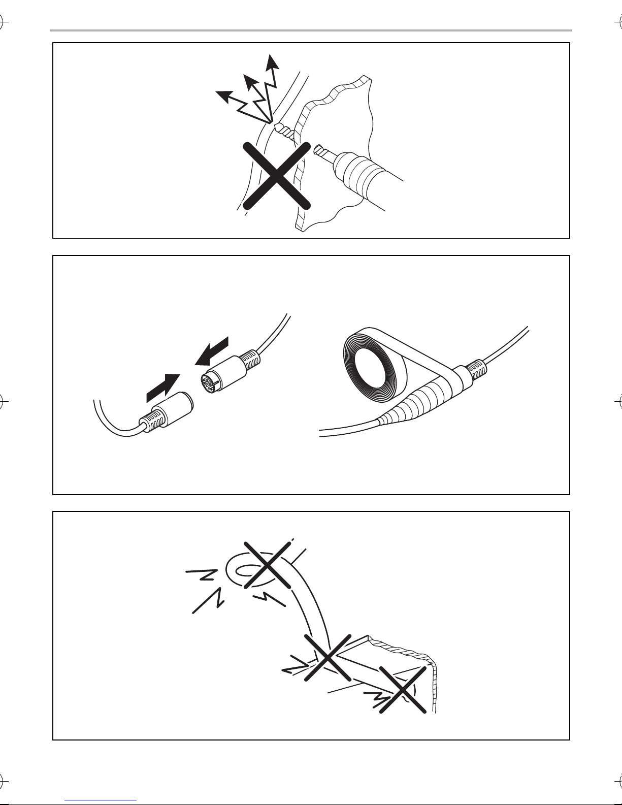
• To prevent damage to the cables when laying them, ensure that they are far enough away from
hot or moving vehicle components (exhaust pipes, drive shafts, light systems, fans, heaters,
etc.).
• Use adhesive insulating tape to prevent water from penetrating the plug connection (fig. 7,
page 6).
14
Page 15

VT50WiFi Connecting the transmitter electrically
EN
• When laying the cables (fig. 8, page 6), make sure:
– they are not kinked or twisted
– they do not rub on edges
– they are not laid in sharp-edged ducts without protection.
• Protect every through-hole made in the bodywork against water penetration, e.g. by using a
cable with a sealant and by spraying the cable and the cable sleeve with sealant.
NOTE
I
7.2 Connecting the transmitter electrically
A
I
Only start sealing through-holes when you have completed all installation work on the
camera and have laid the required cable lengths.
NOTICE!
Make sure the polarity is correct.
NOTE
The transmitter creates a wireless network that does not permit access to the Internet.
Therefore internet services cannot be used once the transmitter is being supplied with
power.
The use of telephony and text messages is also restricted.
Connecting the transmitter to the reversing light
NOTE
I
Proceed as follows (fig. 2, page 3):
➤ Connect the red cable of the transmitter (3) to the positive cable of the reversing light.
➤ Connect the black cable of the transmitter (4) to the earth wire (–) on the reversing light or to
the earth terminal on the bodywork.
➤ Connect the transmitter to the camera (fig. 9, page 7):
– Plug the connection cable (1) together.
– Insert the plug (2) into the transmitter’s camera connection (3).
✓ After a few seconds, the VT50WiFi establishes the digital wireless connection.
On some vehicles, the reversing light only works when the ignition is switched on. In
this case, you must switch on the ignition to identify the positive and earth cables.
15
Page 16

Using VT50WiFi VT50WiFi
EN
8Using VT50WiFi
8.1 Installing the VT50 RearCam app
To be able to use the system, you need to install the manufacturer’s free app on your receiving
device before initial use.
You can find the app in Google Play Store™ (Android™) and in the App Store™ (iOS™) under the
name VT50 RearCam.
8.2 Putting VT50WiFi into operation
NOTE
I
➤ Activate the wireless reception of your receiving device.
➤ Switch the vehicle ignition on.
Change the name and password of the wireless network after you have connected
your receiving device for the first time.
➤ Engage the reverse gear of the vehicle.
✓ The transmitter is operational about six seconds after putting the vehicle into reverse gear. The
operating display (fig. 2 5page 3) lights up permanently in red on the transmitter.
➤ Connect your receiving device to the wireless network of the transmitter.
➤ Start the app on your receiving device.
✓ The receiving device displays the camera image.
9 Troubleshooting
Fault Cause Suggested remedy
The receiving device cannot find the transmitter’s
wireless network.
The transmitter’s operating display does not light
up.
The app on the receiving
device has a black
screen.
The transmitter does not
work.
The transmitter does not
work.
Check the power supply.
Check whether the app responds:
Open the menu.
Check the transmitter connection and
function.
The receiving device cuts
off during image playback.
The connection between
transmitter and receiving
device is too weak.
16
Adjust the location of the transmitter by
a few centimetres.
Page 17

VT50WiFi Warranty
EN
10 Warranty
The statutory warranty period applies. If the product is defective, please contact the
manufacturer's branch in your country (see the back of the instruction manual for the addresses) or
your retailer.
For repair and guarantee processing, please include the following documents when you send in
the device:
• A copy of the receipt with purchasing date
• A reason for the claim or description of the fault
11 Disposal
➤ Place the packaging material in the appropriate recycling waste bins wherever possible.
If you wish to finally dispose of the product, ask your local recycling centre or specialist
dealer for details about how to do this in accordance with the applicable disposal
M
regulations.
17
Page 18

Technical data VT50WiFi
EN
12 Technical data
VT50WiFi
Ref. no.: 9600003262
Image sensor: CMOS
Pixels: 300000 pixels
Sensitivity: < 1 lux
Delay: 200 ms
Time needed to establish connection: < 10 s
Resolution: VGA
Videocodec: MPEG4
TV system: PAL
WLAN frequency: 2412 – 2483.5 MHz
WLAN standard: WIFI 802.11 g/n (QPSK, 16QAM)
Transmission distance (direct vision): 15 m
Operating voltage: 9 – 16 Vg
Amperage: 200 mA
Operating temperature: –20 °C to +70 °C
Camera dimensions (without assembly
plate):
Transmitter dimensions (without
antenna):
Weight (camera and transmitter): 150 g
62 x 27 x 26 mm
45 x 47 x 20 mm
18
Page 19

VT50WiFi Erklärung der Symbole
DE
Bitte lesen Sie diese Anleitung vor Einbau und Inbetriebnahme sorgfältig durch und
bewahren Sie sie auf. Geben Sie sie im Falle einer Weitergabe des Produktes an den
Nutzer weiter.
Inhaltsverzeichnis
1 Erklärung der Symbole . . . . . . . . . . . . . . . . . . . . . . . . . . . . . . . . . . . . . . . . . . . . . . . . . . . . . . 19
2 Sicherheits- und Einbauhinweise. . . . . . . . . . . . . . . . . . . . . . . . . . . . . . . . . . . . . . . . . . . . . .20
3 Lieferumfang . . . . . . . . . . . . . . . . . . . . . . . . . . . . . . . . . . . . . . . . . . . . . . . . . . . . . . . . . . . . . .22
4 Bestimmungsgemäßer Gebrauch . . . . . . . . . . . . . . . . . . . . . . . . . . . . . . . . . . . . . . . . . . . . .22
5 Technische Beschreibung . . . . . . . . . . . . . . . . . . . . . . . . . . . . . . . . . . . . . . . . . . . . . . . . . . .22
6 Kamera und Sender montieren . . . . . . . . . . . . . . . . . . . . . . . . . . . . . . . . . . . . . . . . . . . . . . .23
7 Sender elektrisch anschließen . . . . . . . . . . . . . . . . . . . . . . . . . . . . . . . . . . . . . . . . . . . . . . . .25
8 VT50WiFi benutzen . . . . . . . . . . . . . . . . . . . . . . . . . . . . . . . . . . . . . . . . . . . . . . . . . . . . . . . .27
9 Störungsbeseitigung . . . . . . . . . . . . . . . . . . . . . . . . . . . . . . . . . . . . . . . . . . . . . . . . . . . . . . .27
10 Gewährleistung . . . . . . . . . . . . . . . . . . . . . . . . . . . . . . . . . . . . . . . . . . . . . . . . . . . . . . . . . . .28
11 Entsorgung . . . . . . . . . . . . . . . . . . . . . . . . . . . . . . . . . . . . . . . . . . . . . . . . . . . . . . . . . . . . . . .28
12 Technische Daten . . . . . . . . . . . . . . . . . . . . . . . . . . . . . . . . . . . . . . . . . . . . . . . . . . . . . . . . . .29
1 Erklärung der Symbole
WARNUNG!
!
!
A
Sicherheitshinweis: Nichtbeachtung kann zu Tod oder schwerer Verletzung führen.
VORSICHT!
Sicherheitshinweis: Nichtbeachtung kann zu Verletzungen führen.
ACHTUNG!
Nichtbeachtung kann zu Materialschäden führen und die Funktion des Produktes
beeinträchtigen.
HINWEIS
I
Ergänzende Informationen zur Bedienung des Produktes.
19
Page 20

Sicherheits- und Einbauhinweise VT50WiFi
DE
2 Sicherheits- und Einbauhinweise
Der Hersteller übernimmt in folgenden Fällen keine Haftung für Schäden:
• Beschädigungen am Produkt durch mechanische Einflüsse und Überspannungen
• Veränderungen am Produkt ohne ausdrückliche Genehmigung vom Hersteller
• Verwendung für andere als die in der Anleitung beschriebenen Zwecke
Beachten Sie die vom Fahrzeughersteller und vom Kfz-Handwerk vorgeschriebenen
Sicherheitshinweise und Auflagen!
WARNUNG!
Unzureichende Leitungsverbindungen können zur Folge haben, dass durch Kurzschluss
!
A
• Kabelbrände entstehen,
• der Airbag ausgelöst wird,
• elektronische Steuerungseinrichtungen beschädigt werden,
• elektrische Funktionen ausfallen (Blinker, Bremslicht, Hupe, Zündung, Licht).
ACHTUNG!
Klemmen Sie wegen der Kurzschlussgefahr vor Arbeiten an der Fahrzeugelektrik immer
den Minuspol ab.
Bei Fahrzeugen mit Zusatzbatterie müssen Sie an dieser ebenfalls den Minuspol
abklemmen.
Beachten Sie deshalb folgende Hinweise:
• Verwenden Sie bei Arbeiten an den folgenden Leitungen nur isolierte Kabelschuhe, Stecker
und Flachsteckhülsen:
– 30 (Eingang von Batterie Plus direkt)
– 15 (Geschaltetes Plus, hinter Batterie)
– 31 (Rückleitung ab Batterie, Masse)
– L (Blinkerleuchten links)
– R (Blinkerleuchten rechts)
Verwenden Sie keine Lüsterklemmen.
• Verwenden Sie eine Krimpzange zum Verbinden der Kabel.
• Schrauben Sie das Kabel bei Anschlüssen an Leitung 31 (Masse)
– mit Kabelschuh und Zahnscheibe an eine fahrzeugeigene Masseschraube oder
– mit Kabelschuh und Blechschraube an das Karosserieblech.
Achten Sie auf eine gute Masseübertragung!
20
Page 21

VT50WiFi Sicherheits- und Einbauhinweise
DE
Beim Abklemmen des Minuspols der Batterie verlieren alle flüchtigen Speicher der Komfortelektronik ihre gespeicherten Daten.
• Folgende Daten müssen Sie je nach Fahrzeugausstattung neu einstellen:
–Radiocode
–Fahrzeuguhr
– Zeitschaltuhr
– Bordcomputer
– Sitzposition
Hinweise zur Einstellung finden Sie in der jeweiligen Bedienungsanleitung.
Beachten Sie folgende Hinweise bei der Montage:
VORSICHT!
!
A
Beachten Sie folgende Hinweise bei der Arbeit an elektrischen Teilen:
A
• Befestigen Sie die im Fahrzeug montierten Teile so, dass sie sich unter keinen
Umständen (scharfes Abbremsen, Verkehrsunfall) lösen und zu Verletzungen der
Fahrzeuginsassen führen können.
• Befestigen Sie verdeckt unter Verkleidungen anzubringende Teile des Systems so,
dass sie sich nicht lösen oder andere Teile und Leitungen beschädigen und keine
Fahrzeugfunktionen (Lenkung, Pedale usw.) beeinträchtigen können.
• Beachten Sie immer die Sicherheitshinweise des Fahrzeugherstellers.
Einige Arbeiten (z. B. an Rückhaltesystemen wie Airbag usw.) dürfen nur von
geschultem Fachpersonal durchgeführt werden.
ACHTUNG!
• Achten Sie beim Bohren auf ausreichenden Freiraum für den Bohreraustritt, um
Schäden zu vermeiden.
• Entgraten Sie jede Bohrung und behandeln Sie diese mit Rostschutzmittel.
ACHTUNG!
• Benutzen Sie zum Prüfen der Spannung in elektrischen Leitungen nur eine Diodenprüflampe oder ein Voltmeter.
Prüflampen mit einem Leuchtkörper nehmen zu hohe Ströme auf, wodurch die
Fahrzeugelektronik beschädigt werden kann.
• Beachten Sie beim Verlegen der elektrischen Anschlüsse, dass diese
– nicht geknickt oder verdreht werden,
– nicht an Kanten scheuern,
– nicht ohne Schutz durch scharfkantige Durchführungen verlegt werden.
• Isolieren Sie alle Verbindungen und Anschlüsse.
• Sichern Sie die Kabel gegen mechanische Beanspruchung durch Kabelbinder oder
Isolierband, z. B. an vorhandenen Leitungen.
21
Page 22

Lieferumfang VT50WiFi
DE
3Lieferumfang
Menge Bezeichnung
1 Kamera mit Nummernschildbefestigung
1Sender
– Befestigungsmaterial
1 Anleitung
4 Bestimmungsgemäßer Gebrauch
PerfectView VT50WiFi (Art.-Nr. 9600003262) ist eine Rückfahrvideokamera mit einem WiFiSender. Der Sender dient zur kabellosen Übertragung der Signale zwischen der Rückfahrvideokamera und einem Smartphone oder Tablet mit iOS™- oder Android™-Betriebssystem.
PerfectView VT50WiFi eignet sich ausschließlich für die Anwendung an PKWs (Abb. 1, Seite 3).
5 Technische Beschreibung
5.1 Funktionsbeschreibung
PerfectView VT50WiFi besteht aus einer Rückfahrvideokamera mit Nummernschildbefestigung,
einem WiFi-Sender und einer App für mobile Endgeräte wie Smartphones oder Tablets.
Der Sender wird im Fahrzeug montiert. Er baut ein WLAN-Funknetz auf und überträgt darüber das
Bild zum Smartphone oder Tablet.
Der Sender wird an den Rückfahrscheinwerfer angeschlossen und dient gleichzeitig als Stromversorgung für die Kamera. Der Sender muss die WLAN-Verbindung bei jedem Einlegen des
Rückwärtsgangs neu aufbauen. Dies benötigt etwa sechs Sekunden.
Die Funksignale werden im 2,4-GHz-Bereich übertragen.
Das System stellt eine Unterstützung dar, es entbindet Sie jedoch nicht von der besonderen
Vorsichtspflicht beim Fahren mit Anhängern.
ACHTUNG!
A
Der Sender überträgt digitale Daten. Das Kamerabild wird mit einer Verzögerung von
0,2 s am Monitor angezeigt. Fahren Sie deshalb unbedingt langsam.
22
Page 23

VT50WiFi Kamera und Sender montieren
DE
5.2 Bedienelemente
Nr. in
Abb. 2, Seite 3
1 Antennenanschluss
2 Kameraanschluss
3 Rote Ader (DC INPUT): Anschluss an Pluspol (+) der Stromquelle
4 Schwarze Ader (GND): Anschluss an Minuspol (–) der Stromquelle
5 Betriebsanzeige: leuchtet, wenn Spannung anliegt
Bedeutung
oder an Masse-Klemme
6 Kamera und Sender montieren
6.1 Benötigtes Werkzeug (Abb. 3, Seite 4)
Für Einbau und Montage benötigen Sie folgende Werkzeuge:
• Satz Bohrer (1)
• Bohrmaschine (2)
• Schraubendreher (3)
• Satz Ring- oder Maulschlüssel (4)
• Metermaß (5)
• Hammer (6)
• Körner (7)
Für den elektrischen Anschluss und seine Überprüfung benötigen Sie folgende Hilfsmittel:
• Diodenprüflampe (8) oder Voltmeter (9)
• Krimpzange (10)
• Isolierband (11)
• Ggf. Kabeldurchführungstüllen
Zur Befestigung der Kamera, des Senders und der Kabel benötigen Sie ggf. noch weitere
Schrauben, Kabelbinder und Doppelklebeband.
23
Page 24

Kamera und Sender montieren VT50WiFi
DE
6.2 Kamera für Montage vorbereiten
Beachten Sie folgende Hinweise bei der Montage:
• Platzieren Sie die Kamera mittig über oder unter dem Nummernschild. Die Kamera benötigt
einen Freiraum von 30 mm über dem Nummernschild oder unter dem Nummernschild.
• Befestigen Sie die Kamera so, dass das Nummernschild nicht verdeckt wird.
Kamera unter dem Nummernschild montieren (Abb. 4, Seite 5)
➤ Schrauben Sie die Kamera (1) vom Montageblech (2) ab.
➤ Drehen Sie die Kamera um 180°.
➤ Befestigen Sie die Kamera wieder am Montageblech.
Montageposition an Fahrzeugheck anpassen (Abb. 5, Seite 5)
Die Kamera ist am oberen Teil des Montageblechs befestigt. Der obere Teil des Montageblechs
ist in einem Winkel von etwa 5° gebogen. Sie können die Kamera auf der Rückseite des Montageblechs anbringen, um die Montageposition an die Form des Fahrzeughecks anzupassen.
➤ Schrauben Sie die Kamera (1) vom Montageblech (2) ab.
➤ Drehen Sie das Montageblech um 180°.
➤ Befestigen Sie die Kamera wieder am Montageblech.
6.3 Kamera befestigen
➤ Entfernen Sie den hinteren Nummernschildhalter vom Fahrzeug.
➤ Befestigen Sie das Montageblech der Kamera mit Doppelklebeband an der Rückseite des
Nummernschildhalters.
➤ Befestigen Sie den Nummernschildhalter wieder am Fahrzeug. Drücken Sie dabei das
Doppelklebeband an die Karosserie.
✓ Die Kamera ist jetzt am Fahrzeug befestigt.
6.4 Sender für Montage vorbereiten
VORSICHT!
!
Beachten Sie folgende Hinweise bei der Montage:
Wählen Sie den Platz des Senders so aus, dass unter keinen Umständen (z. B. durch
scharfes Abbremsen, Verkehrsunfall) Fahrzeuginsassen verletzt werden können.
• Montieren Sie den Sender so, dass sich möglichst wenige Objekte zwischen Sender und
Empfangsgerät befinden. Bei schlechter Verbindung kann das Versetzen des Senders helfen.
• Der Montageort sollte eben sein.
• Kontrollieren Sie vor jedem Bohren, ob ausreichender Freiraum für den Bohreraustritt
vorhanden ist (Abb. 6, Seite 6).
• Stellen Sie sicher, dass Sie das Anschlusskabel vom Sender zur Kamera verlegen können.
24
Page 25

VT50WiFi Sender elektrisch anschließen
DE
HINWEIS
I
Das Bild wird vom Sender zum Empfangsgerät übertragen. Für eine einwandfreie
Funktion müssen Sie vor der endgültigen Montage prüfen, ob die Funkübertragung
stabil ist.
6.5 Sender befestigen
➤ Befestigen Sie den Sender provisorisch am geplanten Montageort.
➤ Nehmen Sie den Sender in Betrieb.
➤ Aktivieren Sie die App auf Ihrem Empfangsgerät (siehe Kapitel „VT50WiFi benutzen“ auf
Seite 27).
Wenn Störungen auftreten, z. B. ruckelnde Bildübertragung:
➤ Versetzen Sie den Sender leicht.
➤ Testen Sie die Übertragung erneut.
Wenn das Kamerabild stabil übertragen wird (kein Bildruckeln):
➤ Befestigen Sie den Sender mit dem Doppelklebeband.
7 Sender elektrisch anschließen
7.1 Allgemeine Hinweise zur Kabelverlegung
HINWEIS
I
• Verwenden Sie für die Durchführung der Anschlusskabel nach Möglichkeit
Originaldurchführungen oder andere Durchführungsmöglichkeiten, z. B.
Verkleidungskanten, Lüftungsgitter oder Blindschalter.
Wenn keine Durchführungen vorhanden sind, müssen Sie für die jeweiligen Kabel
entsprechende Löcher bohren. Schauen Sie vorher nach, ob ausreichender
Freiraum für den Bohreraustritt vorhanden ist.
• Nicht fachgerechte Kabelverlegungen und Kabelverbindungen führen immer
wieder zu Fehlfunktionen oder Beschädigungen von Bauteilen. Eine korrekte
Kabelverlegung bzw. Kabelverbindung ist die Grundvoraussetzung für eine
dauerhafte und fehlerfreie Funktion der nachgerüsteten Komponenten.
Beachten Sie deshalb folgende Hinweise:
• Verlegen Sie die Kabel nach Möglichkeit immer im Fahrzeuginneren, denn dort sind sie besser
geschützt als außen am Fahrzeug.
Wenn Sie die Kabel trotzdem außerhalb des Fahrzeuges verlegen, achten Sie auf eine sichere
Befestigung (durch zusätzliche Kabelbinder, Isolierband usw.).
• Um Beschädigungen am Kabel zu vermeiden, halten Sie beim Verlegen der Kabel immer
ausreichend Abstand zu heißen und sich bewegenden Fahrzeugteilen (Auspuffrohre,
Antriebswellen, Lichtmaschine, Lüfter, Heizung usw.).
25
Page 26

Sender elektrisch anschließen VT50WiFi
DE
• Verwenden Sie Isolierklebeband, um das Eindringen von Wasser in die Steckverbindungen zu
verhindern (Abb. 7, Seite 6).
• Beachten Sie beim Verlegen der Kabel (Abb. 8, Seite 6), dass diese
– nicht stark geknickt oder verdreht werden,
–nicht an Kanten scheuern,
– nicht ohne Schutz durch scharfkantige Durchführungen verlegt werden.
• Schützen Sie jeden Durchbruch an der Außenhaut durch geeignete Maßnahmen gegen
Wassereinbruch, z. B. durch Einsetzen des Kabels mit Dichtungsmasse und durch Abspritzen
des Kabels und der Durchführungstülle mit Dichtungsmasse.
HINWEIS
I
7.2 Sender elektrisch anschließen
Beginnen Sie mit dem Abdichten der Durchbrüche erst, nachdem alle Einstellarbeiten
an der Kamera abgeschlossen sind und die benötigten Längen der Anschlusskabel
festliegen.
ACHTUNG!
A
I
Sender an den Rückfahrscheinwerfer anschließen
I
Gehen Sie wie folgt vor (Abb. 2, Seite 3):
➤ Schließen Sie die rote Ader des Senders (3) an die Leitung zum Pluspol des
Rückfahrscheinwerfers an.
Achten Sie auf die richtige Polung.
HINWEIS
Der Sender erzeugt ein WLAN-Netz, das keinen Zugang zum Internet ermöglicht.
Internetdienste sind daher nicht mehr nutzbar, sobald der Sender mit Strom versorgt
wird.
Telefonie und SMS sind weiterhin uneingeschränkt nutzbar.
HINWEIS
Bei manchen Fahrzeugen funktioniert der Rückfahrscheinwerfer nur bei
eingeschalteter Zündung. In diesem Fall müssen Sie die Zündung einschalten, um die
Plus- und die Masseleitung zu bestimmen.
➤ Schließen Sie die schwarze Ader des Senders (4) an die Masseleitung (–) des
Rückfahrscheinwerfers oder an die Masse-Klemme der Karosserie an.
➤ Verbinden Sie den Sender mit der Kamera (Abb. 9, Seite 7):
– Stecken Sie das Anschlusskabel (1) zusammen.
– Stecken Sie den Stecker (2) in den Kameraanschluss (3) des Senders.
✓ Nach einigen Sekunden baut VT50WiFi die digitale Funkverbindung auf.
26
Page 27

VT50WiFi VT50WiFi benutzen
DE
8 VT50WiFi benutzen
8.1 Die App VT50 RearCam installieren
Um das System nutzen zu können, müssen Sie vor der ersten Nutzung die kostenlose App des
Herstellers auf Ihrem Empfangsgerät installieren.
Sie finden die App im Google Play Store™ (Android™) und im App Store™ (iOS™) unter dem
Namen VT50 RearCam.
8.2 VT50WiFi in Betrieb nehmen
HINWEIS
I
➤ Aktivieren Sie den WLAN-Empfang Ihres Empfangsgerätes.
➤ Schalten Sie die Zündung des Fahrzeugs ein.
Ändern Sie den Namen und das Passwort des WLANs, nachdem Sie Ihr
Empfangsgerät das erste Mal damit verbunden haben.
➤ Legen Sie den Rückwärtsgang des Fahrzeugs ein.
✓ Etwa sechs Sekunden nach Einlegen des Rückwärtsgangs ist der Sender betriebsbereit.Die
Betriebsanzeige (Abb. 2 5,Seite 3) am Sender leuchtet dauerhaft rot.
➤ Verbinden Sie Ihr Empfangsgerät mit dem WLAN des Senders.
➤ Starten Sie die App auf Ihrem Empfangsgerät.
✓ Das Empfangsgerät zeigt das Bild der Kamera.
9 Störungsbeseitigung
Störung Ursache Lösungsvorschlag
Das Empfangsgerät kann
das WLAN des Senders
nicht finden.
Die Betriebsanzeige des
Senders leuchtet nicht.
Die App auf dem
Empfangsgerät zeigt
einen schwarzen
Bildschirm.
Der Sender arbeitet nicht. Prüfen Sie die Stromversorgung.
Der Sender arbeitet nicht. Prüfen Sie, ob die App reagiert: Öffnen
Sie das Menü.
Prüfen Sie Anschluss und Funktion des
Senders.
Das Empfangsgerät
stockt bei der Bildwiedergabe.
Die Verbindung zwischen
Sender und Empfangsgerät ist zu schwach.
Versetzen Sie den Sender um einige
Zentimeter.
27
Page 28

Gewährleistung VT50WiFi
DE
10 Gewährleistung
Es gilt die gesetzliche Gewährleistungsfrist. Sollte das Produkt defekt sein, wenden Sie sich bitte
an die Niederlassung des Herstellers in Ihrem Land (Adressen siehe Rückseite der Anleitung) oder
an Ihren Fachhändler.
Zur Reparatur- bzw. Gewährleistungsbearbeitung müssen Sie folgende Unterlagen mitschicken:
• eine Kopie der Rechnung mit Kaufdatum,
• einen Reklamationsgrund oder eine Fehlerbeschreibung.
11 Entsorgung
➤ Geben Sie das Verpackungsmaterial möglichst in den entsprechenden Recycling-Müll.
Wenn Sie das Produkt endgültig außer Betrieb nehmen, informieren Sie sich bitte beim
nächsten Recyclingcenter oder bei Ihrem Fachhändler über die zutreffenden
M
Entsorgungsvorschriften.
28
Page 29

VT50WiFi Technische Daten
DE
12 Technische Daten
VT50WiFi
Art.-Nr.: 9600003262
Bildsensor: CMOS
Bildpunkte: 300000 Pixel
Empfindlichkeit: < 1 Lux
Verzögerung: 200 ms
Dauer des Verbindungsaufbaus: < 10 s
Auflösung: VGA
Videocodec: MPEG4
TV-System: PAL
WLAN-Frequenz: 2412 – 2483,5 MHz
WLAN-Standard: WIFI 802.11 g/n (QPSK, 16QAM)
Übertragungsdistanz (direkte Sicht): 15 m
Betriebsspannung: 9 – 16 Vg
Stromstärke: 200 mA
Betriebstemperatur: –20 °C bis +70 °C
Abmessungen Kamera
(ohne Montageblech):
Abmessungen Sender (ohne Antenne): 45 x 47 x 20 mm
Gewicht (Kamera und Sender): 150 g
62 x 27 x 26 mm
29
Page 30

Explication des symboles VT50WiFi
FR
Veuillez lire attentivement cette notice avant le montage et la mise en service. Veuillez
ensuite la conserver. En cas de passer le produit, veuillez le transmettre au nouvel
acquéreur.
Sommaire
1 Explication des symboles. . . . . . . . . . . . . . . . . . . . . . . . . . . . . . . . . . . . . . . . . . . . . . . . . . . .30
2 Consignes de sécurité et instructions de montage. . . . . . . . . . . . . . . . . . . . . . . . . . . . . . . . 31
3 Contenu de la livraison. . . . . . . . . . . . . . . . . . . . . . . . . . . . . . . . . . . . . . . . . . . . . . . . . . . . . .33
4 Usage conforme . . . . . . . . . . . . . . . . . . . . . . . . . . . . . . . . . . . . . . . . . . . . . . . . . . . . . . . . . . .33
5 Description technique . . . . . . . . . . . . . . . . . . . . . . . . . . . . . . . . . . . . . . . . . . . . . . . . . . . . . .33
6 Montage de la caméra et de l'émetteur . . . . . . . . . . . . . . . . . . . . . . . . . . . . . . . . . . . . . . . .34
7 Raccordement électrique de l'émetteur . . . . . . . . . . . . . . . . . . . . . . . . . . . . . . . . . . . . . . . .36
8 Utilisation du VT50WiFi . . . . . . . . . . . . . . . . . . . . . . . . . . . . . . . . . . . . . . . . . . . . . . . . . . . . .38
9 Guide de dépannage . . . . . . . . . . . . . . . . . . . . . . . . . . . . . . . . . . . . . . . . . . . . . . . . . . . . . . .39
10 Garantie. . . . . . . . . . . . . . . . . . . . . . . . . . . . . . . . . . . . . . . . . . . . . . . . . . . . . . . . . . . . . . . . . .39
11 Retraitement . . . . . . . . . . . . . . . . . . . . . . . . . . . . . . . . . . . . . . . . . . . . . . . . . . . . . . . . . . . . . .39
12 Caractéristiques techniques. . . . . . . . . . . . . . . . . . . . . . . . . . . . . . . . . . . . . . . . . . . . . . . . . .40
1 Explication des symboles
AVERTISSEMENT !
!
!
Consigne de sécurité : le non-respect de ces consignes peut entraîner la mort ou de
graves blessures.
ATTENTION !
Consigne de sécurité : le non-respect de ces consignes peut entraîner des bles-
sures.
AVIS !
A
I
30
Le non-respect de ces consignes peut entraîner des dommages matériels et des
dysfonctionnements du produit.
REMARQUE
Informations complémentaires sur l'utilisation du produit.
Page 31

VT50WiFi Consignes de sécurité et instructions de montage
FR
2 Consignes de sécurité et instructions de montage
Le fabricant décline toute responsabilité pour des dommages dans les cas suivants :
• des influences mécaniques et des surtensions ayant endommagé le matériel
• des modifications apportées au produit sans autorisation explicite de la part du fabricant
• une utilisation différente de celle décrite dans la notice
Respectez les consignes de sécurité et autres prescriptions imposées par le fabricant
du véhicule et par les professionnels de l'automobile !
AVERTISSEMENT !
Tout branchement électrique inadéquat peut entraîner un court-circuit causant
!
• la combustion de câbles,
• le déclenchement de l'airbag,
• l’endommagement des dispositifs électroniques de commande,
• la défaillance des fonctions électriques (clignotants, feux-stop, klaxon, allumage,
éclairage).
AVIS !
Débranchez toujours la borne négative avant de procéder à des travaux sur les éléments
A
Veuillez donc respecter les consignes suivantes :
• Pour tous les travaux sur les lignes électriques suivantes, n’utilisez que des cosses de câble,
fiches et alvéoles pour contacts plats isolés :
– 30 (entrée directe pôle positif de la batterie)
–15 (pôle positif connecté, derrière la batterie)
– 31 (ligne de retour à partir de la batterie, masse)
– L (clignotants gauches)
– R (clignotants droits)
N’utilisez pas de dominos.
• Utilisez une pince à sertir pour relier les câbles.
• Pour les raccordements à la ligne électrique 31 (masse), vissez le câble
– à une vis de masse du véhicule, avec une cosse et une rondelle crantée, ou bien
– à la carrosserie, avec une cosse et une vis à tôle.
électriques du véhicule afin d’éviter tout risque de court-circuit.
Sur les véhicules équipés d’une batterie supplémentaire, vous devez également
débrancher le pôle négatif de cette dernière.
Veillez à une bonne transmission de la masse !
31
Page 32

Consignes de sécurité et instructions de montage VT50WiFi
FR
Lorsque vous débranchez le pôle négatif de la batterie, les mémoires volatiles de l’électronique de
confort perdent toutes les données enregistrées.
• Vous devez procéder à un nouveau réglage des données suivantes en fonction de l’équipement du véhicule :
–code radio
– horloge du véhicule
–minuterie
– ordinateur de bord
– position du siège
Les instructions de réglage figurent dans les notices d’utilisation correspondantes.
Veuillez respecter les consignes suivantes lors du montage :
ATTENTION !
!
A
Veuillez respecter les consignes suivantes pour les travaux sur les éléments électriques :
A
• Fixez les pièces installées dans le véhicule de manière à ce qu’elles ne puissent en
aucun cas se desserrer (freinage abrupt, accident) et risquer de causer des blessures
aux occupants du véhicule.
• Fixez les pièces du système sous l'habillage de telle sorte qu'elles ne puissent pas se
détacher, endommager d'autres pièces ou connexions, ni gêner le fonctionnement
du véhicule (direction, pédales, etc.).
• Respectez toujours les consignes de sécurité du fabricant du véhicule.
Certains travaux (p. ex. au niveau des systèmes de retenue, AIRBAG, etc.) doivent
être effectués uniquement par un personnel spécialisé ayant reçu une formation
correspondante.
AVIS !
• Avant de percer des trous, assurez-vous que vous disposez d’un espace suffisant de
l'autre côté du trou à percer afin que la mèche n'occasionne aucun dégât.
• Ebavurez tous les trous et protégez-les avec un enduit anticorrosif.
AVIS !
• Pour le contrôle de la tension des lignes électriques, n’utilisez qu’une lampe étalon à
diode ou un voltmètre.
Les lampes étalons à corps lumineux absorbent des courants trop élevés qui
pourraient endommager les composants électroniques du véhicule.
• Lors de l'installation des raccordements électriques, veillez à ce que ceux-ci
– ne soient ni pliés, ni tordus,
– ne frottent pas contre des arêtes,
– ne soient pas placés dans des passages à arêtes vives sans protection.
• Isolez toutes les connexions et tous les raccords.
• Protégez les câbles contre toute contrainte mécanique en les fixant par exemple aux
lignes existantes à l'aide de serre-câbles ou de ruban vinyle.
32
Page 33

VT50WiFi Contenu de la livraison
FR
3 Contenu de la livraison
Quantité Désignation
1 Caméra avec fixation pour plaque d'immatriculation
1Émetteur
–Matériel de fixation
1Manuel
4Usage conforme
PerfectView VT50WiFi (n° d'art. 9600003262) est une caméra vidéo de recul avec un émetteur
WiFi. L'émetteur est utilisé pour la transmission sans fil de signaux entre la caméra vidéo de recul
et un smartphone ou une tablette avec système d'exploitation iOS™ ou Android™.
PerfectView VT50WiFi doit être utilisé exclusivement sur les voitures (fig. 1, page 3).
5 Description technique
5.1 Description du fonctionnement
PerfectView VT50WiFi se compose d'une caméra vidéo avec fixation pour plaque d'immatriculation, d'un émetteur Wi-Fi et d'une application pour les appareils mobiles comme les smartphones
ou les tablettes.
L'émetteur est monté dans le véhicule. Il établit un réseau radio Wi-Fi et transmet ainsi l'image au
smartphone ou à la tablette.
L'émetteur est raccordé au feu de recul et sert en même temps d'alimentation électrique pour la
caméra. L'émetteur doit rétablir la connexion Wi-Fi à chaque enclenchement de la marche arrière
Cela prend environ six secondes.
Les signaux radio sont transmis sur 2,4 GHz.
Le système vous apporte une aide supplémentaire, mais cet appareil ne vous dispense pas du
devoir de prudence qui vous incombe lorsque vous conduisez avec des remorques.
AVIS !
A
L'émetteur transmet des données numériques. L'image de la caméra apparaît dans un
délai de 0,2 s sur le moniteur. Vous devez donc absolument rouler lentement.
33
Page 34

Montage de la caméra et de l'émetteur VT50WiFi
FR
5.2 Éléments de commande
N° dans
fig. 2, page 3
1 Raccordement de l'antenne
2 Raccordement de la caméra
3 Fil rouge (DC INPUT) : Raccordement au pôle positif (+) de la source
4 Fil noir (GND) : raccordement au pôle négatif (–) de la source de
5 Témoin lumineux de fonctionnement ; s'allume lorsque la tension est
Signification
de courant
tension ou à la borne de masse
présente
6 Montage de la caméra et de l'émetteur
6.1 Outils nécessaires (fig. 3, page 4)
Pour la mise en place et le montage, vous devez disposer des outils suivants :
• Jeu de mèches (1)
• Perceuse (2)
• Tournevis (3)
• Jeu de clés à œil ou de clés plates (4)
• Mètre-ruban (5)
• Marteau (6)
• Pointeau (7)
Pour le raccordement électrique et la vérification de celui-ci, vous devez disposer du matériel
suivant :
• Lampe étalon à diode (8) ou voltmètre (9)
• Pince de sertissage (10)
• Ruban vinyle (11)
• Si nécessaire, passe-câbles
Pour la fixation de la caméra, de l'émetteur et des câbles, vous pourriez avoir besoin de vis,
de raccords pour câbles et de ruban adhésif double face supplémentaires.
34
Page 35

VT50WiFi Montage de la caméra et de l'émetteur
FR
6.2 Préparation de la caméra pour le montage
Veuillez respecter les consignes suivantes lors du montage :
• Placez la caméra centrée au-dessus ou au-dessous de la plaque d'immatriculation. La caméra a
besoin d'un espace de 30 mm au-dessus de la plaque d'immatriculation ou sous la plaque
d'immatriculation.
• Fixez la caméra de telle sorte que la plaque d'immatriculation ne soit pas couverte.
Montage de la caméra sous la plaque d'immatriculation (fig. 4, page 5)
➤ Dévissez la caméra (1) de la plaque de montage (2).
➤ Tournez la caméra de 180°.
➤ Fixez la caméra sur la plaque de montage.
Adaptation de la position de montage à l'arrière du véhicule (fig. 5, page 5)
La caméra est fixée sur le haut de la plaque de montage. La partie supérieure de la plaque de
montage est pliée à un angle d'environ 5°. Vous pouvez fixer la caméra sur l'arrière de la plaque
de fixation pour adapter la position de montage à la forme de l'extrémité arrière du véhicule.
➤ Dévissez la caméra (1) de la plaque de montage (2).
➤ Tournez la plaque de montage de 180°.
➤ Fixez la caméra sur la plaque de montage.
6.3 Fixation de la caméra
➤ Retirez le support de plaque d'immatriculation arrière du véhicule.
➤ Fixez la plaque de montage de la caméra avec du ruban adhésif double-face à l'arrière du
support de la plaque.
➤ Fixez de nouveau le support de la plaque d'immatriculation sur le véhicule. Ce faisant,
appuyez le ruban double-face sur la carrosserie.
✓ La caméra est maintenant fixée au véhicule.
6.4 Préparer l'émetteur au montage
ATTENTION !
!
Installez l'émetteur à un endroit où il ne risquera en aucun cas de blesser les occupants
du véhicule (p. ex. en cas de freinage violent ou d'accident).
Veuillez respecter les consignes suivantes lors du montage :
• Montez l'émetteur de telle sorte qu'il y ait aussi peu d'objets que possible entre l'émetteur et
le récepteur. En cas de mauvaise connexion, le fait de déplacer l'émetteur peut aider.
• L'emplacement de montage choisi doit être plan.
• Vérifiez avant chaque perçage qu'il y a un espace suffisant de l'autre côté du trou pour le
passage de la mèche (fig. 6, page 6).
• Assurez-vous de pouvoir poser le câble de raccordement de l'émetteur à la caméra.
35
Page 36

Raccordement électrique de l'émetteur VT50WiFi
FR
REMARQUE
I
L'image est transmise de l'émetteur vers le récepteur. Afin de garantir le parfait
fonctionnement, vous devez, avant son montage définitif, contrôler la stabilité de la
transmission radio.
6.5 Fixation de l'émetteur
➤ Fixez provisoirement l'émetteur sur l'emplacement choisi.
➤ Mettez l'émetteur en marche.
➤ Activez l'application sur votre récepteur (voir chapitre « Utilisation du VT50WiFi », page 38).
Si des problèmes surviennent, comme une transmission tremblante de l'image :
➤ Déplacez légèrement l'émetteur.
➤ Testez à nouveau la transmission.
Si l'image de la caméra est transmise de manière stable (sans saccades) :
➤ Fixez l'émetteur avec l'adhésif double face.
7 Raccordement électrique de l'émetteur
7.1 Remarques générales concernant la pose des câbles
REMARQUE
I
Veuillez respecter les consignes suivantes :
• Dans la mesure du possible, ne posez les câbles qu'à l'intérieur du véhicule. Ils y seront mieux
protégés qu'à l'extérieur.
Si vous devez malgré tout faire passer les câbles à l'extérieur du véhicule, veillez à ce qu'ils
soient solidement fixés (en utilisant des serre-fils supplémentaires, du ruban vinyle, etc.).
• Pour la pose des câbles de raccordement, utilisez si possible des passages existants
ou d'autres possibilités de passage telles que les arêtes de garnitures, grilles
d'aération ou interrupteurs intégrés.
Si aucun passage n'est disponible, vous devrez percer des trous pour y faire passer
les câbles. Vérifiez avant le perçage qu'il y a un espace suffisant pour la sortie de la
mèche de l'autre côté du trou.
• Toute erreur de pose ou de branchement des câbles entraîne presque toujours des
dysfonctionnements ou des détériorations des composants. Une pose et un
branchement corrects des câbles sont indispensables au fonctionnement durable
et fiable des composants que vous installez.
• Installez les câbles à une distance suffisante des éléments chauds et/ou mobiles du véhicule
(tuyaux d'échappement, arbres de transmission, dynamo, ventilateurs, chauffage, etc.) qui
pourraient les endommager.
36
Page 37

VT50WiFi Raccordement électrique de l'émetteur
FR
• Utilisez du ruban adhésif isolant pour empêcher l'infiltration d'eau dans les prises de
raccordement (fig. 7, page 6).
• Lors de la pose des câbles(fig. 8, page 6), veillez à ce que ceux-ci
– ne soient ni fortement pliés, ni tordus,
– ne frottent pas contre des arêtes,
– ne soient pas placés dans des traversées à arêtes vives sans protection.
• Veillez à protéger chaque trou percé dans la carrosserie en prenant des mesures appropriées
contre toute infiltration d'eau, par exemple en appliquant du mastic sur le câble et sur le
passe-câble.
REMARQUE
I
7.2 Raccordement électrique de l'émetteur
Les opérations d'étanchéification des ouvertures ne doivent être entreprises que
lorsque tous les réglages de position de la caméra ont été effectués et que les
longueurs de câbles de raccordement nécessaires sont définies.
AVIS !
A
I
Raccordement de l'émetteur au feu de recul
I
Procédez comme suit (fig. 2, page 3) :
➤ Raccordez le fil rouge de l'émetteur (3) à la ligne du pôle positif de la batterie du feu de recul.
➤ Raccordez le fil noir de l'émetteur (4) à la ligne de masse (–) du feu de recul ou à la borne de
masse de la carrosserie.
Respectez la polarité.
REMARQUE
L'émetteur crée un réseau WLAN qui ne permet aucun accès à Internet. Les services
Internet ne peuvent donc plus être utilisés dès que l'émetteur est alimenté en courant.
La téléphonie et les SMS restent utilisables sans limitation.
REMARQUE
Sur certains véhicules, le feu de recul ne fonctionne que lorsque le contact est mis.
Dans ce cas, vous devez mettre le contact pour déterminer la ligne positive et la ligne
de masse.
➤ Raccordez l'émetteur à la caméra (fig. 9, page 7) :
– Branchez le câble de raccordement (1).
– Enfichez le connecteur (2) dans le raccordement de la caméra (3) de l'émetteur.
✓ Après quelques secondes, VT50WiFi établit la communication radio numérique.
37
Page 38

Utilisation du VT50WiFi VT50WiFi
FR
8 Utilisation du VT50WiFi
8.1 Installation de l'App VT50 RearCam
Pour pouvoir utiliser le système, vous devez installer l'application mobile gratuite du fabricant sur
votre appareil récepteur.
Vous trouverez l'application mobile dans le Google Play Store™ (Android™) et dans l'App Store™
(iOS™) sous le nom VT50 RearCam.
8.2 Mise en service de VT50WiFi
REMARQUE
I
➤ Activez la réception WLAN de votre appareil récepteur.
➤ Mettez l'allumage du véhicule en marche.
Modifiez le nom et le mot de passe du WLAN après avoir raccordé votre appareil
récepteur pour la première fois.
➤ Enclenchez la marche arrière du véhicule.
✓ Environ six secondes après l'enclenchement de la marche arrière, l'émetteur est prêt à
l'emploi. Le témoin de fonctionnement (fig. 2 5,page 3) sur l'émetteur s'allume en rouge en
permanence.
➤ Raccordez votre récepteur au WLAN de l'émetteur.
➤ Démarrez l'application mobile sur votre récepteur.
✓ L'appareil récepteur affiche l'image de la caméra.
38
Page 39

VT50WiFi Guide de dépannage
FR
9 Guide de dépannage
Dysfonctionnement Cause Solution proposée
L'appareil récepteur ne
trouve pas le WLAN de
l'émetteur.
Le témoin lumineux de
fonctionnement de
l'émetteur ne s'allume
pas.
L'application mobile sur
l'appareil récepteur
affiche un écran noir.
Le récepteur s'arrête
pendant la lecture de
l'image.
10 Garantie
L'émetteur ne fonctionne
pas.
L'émetteur ne fonctionne
pas.
La connexion entre
l'émetteur et l'appareil
récepteur est trop faible.
Vérifiez l'alimentation électrique.
Contrôlez si l'application mobile
réagit : Ouvrez le menu.
Vérifiez le raccordement et le fonctionnement de l'émetteur.
Déplacez l'émetteur de quelques
centimètres.
Le délai légal de garantie s'applique. Si le produit s'avérait défectueux, veuillez vous adresser à la
filiale du fabricant située dans votre pays (voir adresses au verso du présent manuel) ou à votre
revendeur spécialisé.
Veuillez y joindre les documents suivants pour la gestion des réparations et de la garantie :
• une copie de la facture avec la date d'achat,
• le motif de la réclamation ou une description du dysfonctionnement.
11 Retraitement
➤ Jetez les emballages dans les conteneurs de déchets recyclables prévus à cet effet.
Lorsque vous mettrez votre produit définitivement hors service, informez-vous auprès
du centre de recyclage le plus proche ou auprès de votre revendeur spécialisé sur les
M
prescriptions relatives au retraitement des déchets.
39
Page 40

Caractéristiques techniques VT50WiFi
FR
12 Caractéristiques techniques
VT50WiFi
Réf. : 9600003262
Capteur d'images : circuit intégré à transistors MOS
Pixels : 300000 pixels
Sensibilité : < 1 Lux
Délai : 200 ms
Durée de l'établissement de la
connexion :
Résolution : VGA
Codec vidéo : MPEG4
Système TV : PAL
Fréquence WLAN : 2412 – 2483,5 MHz
Standard WLAN : WIFI 802.11 g/n (QPSK, 16QAM)
Distance de transmission (vue directe) : 15 m
Tension de service : 9 – 16 Vg
Intensité du courant : 200 mA
Température de fonctionnement : De –20 °C à +70 °C
Dimensions de la caméra (sans plaque
de montage) :
Dimensions de l'émetteur (sans
antenne) :
< 10 s
62 x 27 x 26 mm
45 x 47 x 20 mm
Poids (caméra et émetteur) : 150 g
40
Page 41

VT50WiFi Explicación de los símbolos
ES
Lea detenidamente estas instrucciones antes de llevar a cabo la instalación y puesta en
funcionamiento, y consérvelas en un lugar seguro. En caso de vender o entregar el
producto a otra persona, entregue también estas instrucciones.
Índice
1 Explicación de los símbolos. . . . . . . . . . . . . . . . . . . . . . . . . . . . . . . . . . . . . . . . . . . . . . . . . . 41
2 Modo de instalación y seguridad . . . . . . . . . . . . . . . . . . . . . . . . . . . . . . . . . . . . . . . . . . . . .42
3 Volumen de entrega. . . . . . . . . . . . . . . . . . . . . . . . . . . . . . . . . . . . . . . . . . . . . . . . . . . . . . . .44
4 Uso adecuado. . . . . . . . . . . . . . . . . . . . . . . . . . . . . . . . . . . . . . . . . . . . . . . . . . . . . . . . . . . . .44
5 Descripción técnica . . . . . . . . . . . . . . . . . . . . . . . . . . . . . . . . . . . . . . . . . . . . . . . . . . . . . . . .44
6 Montar la cámara y el transmisor . . . . . . . . . . . . . . . . . . . . . . . . . . . . . . . . . . . . . . . . . . . . . .45
7 Conexión eléctrica del transmisor . . . . . . . . . . . . . . . . . . . . . . . . . . . . . . . . . . . . . . . . . . . . .47
8 Utilizar la VT50WiFi . . . . . . . . . . . . . . . . . . . . . . . . . . . . . . . . . . . . . . . . . . . . . . . . . . . . . . . .49
9 Solución de averías. . . . . . . . . . . . . . . . . . . . . . . . . . . . . . . . . . . . . . . . . . . . . . . . . . . . . . . . .49
10 Garantía legal . . . . . . . . . . . . . . . . . . . . . . . . . . . . . . . . . . . . . . . . . . . . . . . . . . . . . . . . . . . . .50
11 Gestión de residuos . . . . . . . . . . . . . . . . . . . . . . . . . . . . . . . . . . . . . . . . . . . . . . . . . . . . . . . .50
12 Datos técnicos . . . . . . . . . . . . . . . . . . . . . . . . . . . . . . . . . . . . . . . . . . . . . . . . . . . . . . . . . . . . 51
1 Explicación de los símbolos
¡ADVERTENCIA!
!
!
A
Indicación de seguridad: su incumplimiento puede acarrear la muerte o graves
lesiones.
¡ATENCIÓN!
Indicación de seguridad: su incumplimiento puede acarrear lesiones.
¡AVISO!
Su incumplimiento puede acarrear daños materiales y perjudicar el correcto funcionamiento del producto.
NOTA
I
Información adicional para el manejo del producto.
41
Page 42

Modo de instalación y seguridad VT50WiFi
ES
2 Modo de instalación y seguridad
El fabricante declina toda responsabilidad ante daños ocurridos en los siguientes casos:
• daños en el producto debido a influencias mecánicas y sobretensiones
• modificaciones realizadas en el producto sin el expreso consentimiento del fabricante
• utilización del aparato para fines distintos a los descritos en las instrucciones
¡Tenga en cuenta las indicaciones de seguridad y la documentación suministrada por
el fabricante y el taller del vehículo!
¡ADVERTENCIA!
Las conexiones eléctricas deficientes pueden provocar, como consecuencia de un
!
cortocircuito, que:
• se quemen los cables,
• se dispare el airbag,
• resulten dañados los dispositivos electrónicos de control,
• queden sin funcionamiento determinadas funciones eléctricas (intermitentes, luz de
freno, claxon, encendido, luz).
¡AVISO!
Desemborne el polo negativo siempre que vaya a trabajar en el sistema eléctrico del
A
Por ello, observe las siguientes indicaciones:
• Al trabajar en los siguientes cables, utilice sólo terminales de cable, conectores y manguitos de
enchufe planos que estén provistos de aislamiento:
– 30 (entrada del polo positivo directo de la batería)
– 15 (polo positivo conectado, detrás de la batería)
– 31 (cable de retorno desde la batería, masa)
– L (lámpara de luz intermitente izquierdo)
– R (lámpara de luz intermitente derecho)
No utilice regletas.
• Utilice una crimpadora para empalmar los cables.
• En el caso de conexiones al cable 31 (masa), atornille el cable
– con terminal de cable y arandela dentada a un tornillo de masa del vehículo, o bien,
– con terminal de cable y tornillo para chapa a la chapa de la carrocería.
vehículo para evitar un cortocircuito.
Desemborne también el polo negativo de la batería adicional en aquellos vehículos que
dispongan de una.
Asegúrese de que se produzca una correcta transmisión de masa.
42
Page 43

VT50WiFi Modo de instalación y seguridad
ES
Tenga en cuenta que al desembornar el polo negativo de la batería se perderán todos los datos
almacenados en las memorias volátiles de la electrónica de confort.
• Dependiendo del equipamiento del vehículo, deberá volver a ajustar los siguientes datos:
– código de la radio
– reloj del vehículo
– reloj programador
– ordenador de a bordo
– posición del asiento
Las indicaciones para realizar los ajustes se encuentran en las instrucciones de uso correspondientes.
Tenga en cuenta las siguientes indicaciones durante el montaje:
¡ATENCIÓN!
!
A
Tenga en cuenta las siguientes indicaciones al trabajar en los componentes eléctricos:
A
• Sujete las piezas montadas en el vehículo de forma que no se puedan soltar bajo
ninguna circunstancia (frenazo o accidente) ni ocasionar lesiones a los ocupantes
del vehículo.
• Fije ocultas bajo revestimientos las partes del sistema que se deban montar, de
manera que no puedan soltarse o dañar otras piezas ni cables, y de manera que no
puedan afectar a las funciones del vehículo (dirección, pedales, etc.).
• Respete siempre las indicaciones de seguridad del fabricante del vehículo.
Algunos trabajos (p. ej. en los sistemas de retención como AIRBAG, etc.) sólo los
puede realizar personal especializado y con la debida formación.
¡AVISO!
• A fin de evitar que se produzcan daños al utilizar el taladro, asegúrese de disponer
de suficiente espacio para la salida de la broca.
• Lije las perforaciones y aplíqueles un antioxidante.
¡AVISO!
• Para comprobar la tensión en los cables eléctricos utilice solamente un diodo de
comprobación o un voltímetro.
Las lámparas de prueba con un elemento luminoso tienen un consumo de corriente
demasiado elevado, por lo que puede dañarse el sistema electrónico del vehículo.
• Al instalar las conexiones eléctricas tenga en cuenta que éstas:
– no se doblen ni se tuerzan,
– no rocen con bordes,
– no se instalen sin protección en canales de paso con bordes afilados.
• Aísle todos los empalmes y conexiones.
• Asegure los cables frente a tracciones mecánicas mediante abrazaderas para cables
o cinta aislante, por ejemplo, fijándolos a los cables eléctricos ya existentes.
43
Page 44

Volumen de entrega VT50WiFi
ES
3 Volumen de entrega
Cantidad Denominación
1 Cámara con mecanismo de fijación a matrícula
1Transmisor
– Material de fijación
1 Instrucciones
4Uso adecuado
La PerfectView VT50WiFi (art.-n.º 9600003262) es una cámara de vídeo de marcha atrás con
transmisor WiFi. El transmisor sirve para la transmisión inalámbrica de señales entre la cámara de
vídeo de marcha atrás y un smartphone o una tableta con sistema operativo iOS™ o Android™. La
PerfectView VT50WiFi está concebida únicamente para su uso en turismos (fig. 1, página 3).
5 Descripción técnica
5.1 Descripción del funcionamiento
PerfectView VT50WiFi consta de una cámara de vídeo de marcha atrás con mecanismo de fijación
a la matrícula, un transmisor WiFi y una app para dispositivos terminales móviles como
smartphones o tabletas.
El transmisor se monta en el vehículo. Establece una red inalámbrica WiFi y, a través de ella,
transmite la imagen al smartphone o a la tableta.
El transmisor se conecta a la luz de marcha atrás y suministra corriente a la cámara. El transmisor
tiene que volver a establecer la conexión WiFi cada vez que se mete la marcha atrás. Para ello
necesita unos seis segundos.
Las señales de radio se transmiten en una banda de frecuencia de 2,4 GHz.
El sistema nos ofrece una ayuda adicional, pero no exime de tomar las precauciones necesarias al
circular con remolques.
¡AVISO!
A
El transmisor transmite datos digitales. La imagen de la cámara aparece en el monitor
con un retardo de 0,2 s. Por eso es necesario que se desplace muy lentamente.
44
Page 45

VT50WiFi Montar la cámara y el transmisor
ES
5.2 Elementos de mando
N.º en
fig. 2, página 3
1 Conexión de la antena
2 Conexión de la cámara
3 Cable rojo (DC INPUT): conexión al polo positivo (+) de la fuente de
4 Cable negro (GND): conexión al polo negativo (–) de la fuente de
5 Indicación de funcionamiento: se ilumina cuando hay tensión
Significado
alimentación
alimentación o al borne de masa
6 Montar la cámara y el transmisor
6.1 Herramientas necesarias (fig. 3, página 4)
Para realizar la instalación y montaje son necesarias las siguientes herramientas:
• juego de brocas (1)
• taladradora (2)
• destornillador (3)
• juego de llaves poligonales o de boca (4)
• metro (5)
• martillo (6)
• punzón para marcar (7)
Para realizar la conexión eléctrica y su comprobación, necesitará los siguientes utensilios:
• diodo de comprobación (8) o voltímetro (9)
• crimpadora (10)
• cinta aislante (11)
• tubos protectores para los cables, si fuese necesario
Para fijar la cámara, el transmisor y los cables puede necesitar más tornillos, abrazaderas para
cables y cinta adhesiva de doble cara.
45
Page 46

Montar la cámara y el transmisor VT50WiFi
ES
6.2 Preparar la cámara para su montaje
Tenga en cuenta las siguientes indicaciones durante el montaje:
• Coloque la cámara centrada encima o debajo de la matrícula. La cámara necesita un espacio
libre de 30 mm por encima de la matrícula o debajo de ella.
• Fije la cámara de modo que no tape la matrícula.
Montar la cámara debajo de la matrícula (fig. 4, página 5)
➤ Desenrosque la cámara (1) de la escuadra de montaje (2).
➤ Gire la cámara 180°.
➤ Vuelva a fijar la cámara a la escuadra de montaje.
Adaptar la posición de montaje a la parte trasera del vehículo (fig. 5, página 5)
La cámara está fijada a la parte superior de la escuadra de montaje. La parte superior de la escuadra
de montaje está doblada con un ángulo de unos 5 . Puede unir la cámara a la parte trasera de la
escuadra de montaje para adaptar la posición de montaje a la forma de la parte trasera del
vehículo.
➤ Desenrosque la cámara (1) de la escuadra de montaje (2).
➤ Gire la escuadra de montaje 180°.
➤ Vuelva a fijar la cámara a la escuadra de montaje.
6.3 Fijar la cámara
➤ Retire del vehículo el soporte trasero de la matrícula.
➤ Fije la escuadra de montaje de la cámara a la cara trasera del soporte de la matrícula con cinta
adhesiva de doble cara.
➤ Vuelva a fijar el soporte de la matrícula al vehículo. Al hacerlo, presione la cinta adhesiva de
doble cara contra la carrocería.
✓ La cámara está fijada al vehículo.
6.4 Preparación del transmisor para su instalación
¡ATENCIÓN!
!
Monte el transmisor en un lugar en el que bajo ninguna circunstancia pueda provocar
heridas a los ocupantes del vehículo (por ejemplo, por frenazos bruscos o accidente).
Tenga en cuenta las siguientes indicaciones durante el montaje:
• Monte el transmisor de manera que entre él y el receptor se interponga la menor cantidad
posible de objetos. Si la conexión es mala, puede servir de ayuda mover el transmisor.
• El lugar de montaje debe ser llano.
• Antes de taladrar, compruebe si se dispone de espacio libre suficiente para la salida de la broca
(fig. 6, página 6).
• Asegúrese de que puede tender el cable de conexión desde el transmisor hasta la cámara.
46
Page 47

VT50WiFi Conexión eléctrica del transmisor
ES
NOTA
I
La imagen se transmite desde el transmisor hasta el receptor. Para garantizar el
correcto funcionamiento del aparato, antes de realizar el montaje definitivo, asegúrese
de que la transmisión de radio es estable.
6.5 Fijar el transmisor
➤ Fije provisionalmente el transmisor en el lugar de montaje previsto.
➤ Ponga el transmisor en funcionamiento.
➤ Active la app en su receptor (véase capítulo “Utilizar la VT50WiFi” en la página 49).
Si se produce algún fallo, p. ej., transmisión discontinua de la imagen:
➤ Desplace ligeramente el transmisor.
➤ Vuelva a probar la transmisión.
Si la imagen transmitida es estable (no hay discontinuidades):
➤ Fije el transmisor con la cinta adhesiva de doble cara.
7 Conexión eléctrica del transmisor
7.1 Indicaciones generales para la instalación de cables
NOTA
I
Por ello, observe las siguientes indicaciones:
• Para tender los cables de conexión utilice, siempre que sea posible, canales de
paso originales u otras posibilidades, como por ejemplo, bordes del revestimiento,
rejillas de ventilación o tapas de interruptores.
Si no existe ningún canal de paso previo, deberá realizar las correspondientes
perforaciones para cada cable. Antes, compruebe si hay suficiente espacio libre
para la salida de la broca.
• La colocación y las conexiones de cables que no hayan sido realizadas por personal
especializado, generalmente tienen como consecuencia el mal funcionamiento o
daños en los componentes. La instalación y conexión correctas de los cables son
requisitos fundamentales para un funcionamiento duradero y correcto de los
accesorios instalados.
• Siempre que sea posible, tienda los cables en el interior del vehículo, puesto que allí estarán
más protegidos que si van por fuera del mismo.
Si a pesar de ello tendiese los cables por la parte externa del vehículo, procure que queden
bien fijos (mediante abrazaderas de cable adicionales, cinta aislante, etc.).
• A fin de evitar daños en los cables, al instalarlos, mantenga una distancia suficiente respecto a
las piezas del vehículo que estén calientes y en movimiento (tubos de escape, ejes de accionamiento, dínamo, ventiladores, calefacción, etc.).
47
Page 48

Conexión eléctrica del transmisor VT50WiFi
ES
• Utilice cinta adhesiva aislante para evitar que entre agua en los conectores (fig. 7, página 6).
• Al tender los cables (fig. 8, página 6) asegúrese de que:
– no se doblen ni se retuerzan,
– no rocen con bordes,
– no se tiendan sin protección a través de guías con aristas afiladas.
• Proteja cada abertura del revestimiento exterior con las medidas adecuadas para evitar que
penetre agua, p. ej. colocando el cable con pasta para juntas y rociando el cable y el tubo
protector con pasta para juntas.
NOTA
I
7.2 Conexión eléctrica del transmisor
A
Comience a sellar las aberturas sólo cuando haya finalizado todos los trabajos de ajuste
en la cámara y cuando haya determinado las longitudes necesarias del cable de
alimentación.
¡AVISO!
Preste atención a la polaridad correcta.
NOTA
I
Conectar el transmisor la luz de marcha atrás
I
Proceda de la siguiente manera (fig. 2, página 3):
➤ Conecte el cable rojo del transmisor (3) al cable que va al polo positivo de la luz de marcha
atrás.
➤ Conecte el cable negro del transmisor (4) al cable a masa (–) de la luz de marcha atrás o al
borne de masa de la carrocería.
El transmisor establece una red WiFi que no permite el acceso a Internet. Por ello, ya
no será posible utilizar los servicios de Internet tan pronto como el transmisor reciba
corriente.
La telefonía y el servicio de SMS sí se pueden seguir utilizando sin ninguna restricción.
NOTA
En algunos vehículos, la luz de marcha atrás funciona solo cuando el encendido del
vehículo está conectado. En ese caso, deberá conectar el encendido para reconocer
el cable positivo y el de masa.
➤ Conecte el transmisor a la cámara (fig. 9, página 7):
– Enchufe el cable de conexión (1).
– Enchufe la clavija (2) en el conector del transmisor para la cámara (3).
✓ Después de unos segundos, VT50WiFi establece la conexión digital por radio.
48
Page 49

VT50WiFi Utilizar la VT50WiFi
ES
8 Utilizar la VT50WiFi
8.1 Instalar la app VT50 RearCam
Para poder utilizar el sistema, se debe instalar primero la app gratuita del fabricante en el receptor.
Encontrará esta app en la Google Play Store™ (Android™) y en la App Store™ (iOS™) bajo el
nombre VT50 RearCam.
8.2 Poner en funcionamiento la VT50WiFi
NOTA
I
➤ Active la recepción WiFi de su receptor.
➤ Conecte el encendido del vehículo.
➤ Engrane la marcha atrás del vehículo.
Cambie el nombre y la contraseña del WiFi después de haber conectado por primera
vez el receptor.
✓ El transmisor está listo para funcionar unos seis segundos después de meter la marcha atrás. La
indicación de funcionamiento (fig. 2 5,página 3) del transmisor se ilumina permanentemente en rojo.
➤ Conecte su receptor al WiFi del transmisor.
➤ Inicie la app en su receptor.
✓ El receptor muestra la imagen de la cámara.
9 Solución de averías
Avería Causa Propuesta de solución
El receptor no encuentra
el WiFi del transmisor.
La indicación de funcionamiento del transmisor
no se ilumina.
La app del receptor
muestra una pantalla
negra.
El transmisor no funciona. Compruebe la alimentación de
corriente.
El transmisor no funciona. Compruebe si reacciona la app: Abra
el menú.
Compruebe la conexión y el funciona-
miento del transmisor.
El receptor reproduce la
imagen con interrupciones.
La conexión entre el transmisor y el receptor es
demasiado débil.
Desplace el transmisor unos centímetros.
49
Page 50

Garantía legal VT50WiFi
ES
10 Garantía legal
Rige el plazo de garantía legal. Si el producto presenta algún defecto, diríjase a la sucursal del
fabricante de su país (ver direcciones en el dorso de estas instrucciones) o a su establecimiento
especializado.
Para la tramitación de la reparación y de la garantía debe enviar también los siguientes documentos:
• una copia de la factura con fecha de compra,
• el motivo de la reclamación o una descripción de la avería.
11 Gestión de residuos
➤ Deseche el material de embalaje en el contenedor de reciclaje correspondiente.
Cuando vaya a desechar definitivamente el producto, infórmese en el centro de
reciclaje más cercano o en un comercio especializado sobre las normas pertinentes de
M
eliminación de materiales.
50
Page 51

VT50WiFi Datos técnicos
ES
12 Datos técnicos
VT50WiFi
N.° de art.: 9600003262
Sensor de imagen: CMOS
Píxeles: 300000 píxeles
Sensibilidad: < 1 lux
Retardo: 200 ms
Duración del establecimiento de cone-
xión:
Resolución: VGA
Códec de vídeo: MPEG4
Norma TV: PAL
Frecuencia de WiFi: 2412 – 2483,5 MHz
Estándar WiFi: WIFI 802.11 g/n (QPSK, 16QAM)
Distancia de transmisión (vista directa): 15 m
Tensión de funcionamiento: 9 – 16 Vg
Intensidad de corriente: 200 mA
Temperatura de funcionamiento: de –20 °C a +70 °C
Dimensiones de la cámara (sin escuadra
de montaje):
Dimensiones del transmisor (sin antena): 45 x 47 x 20 mm
< 10 s
62 x 27 x 26 mm
Peso (cámara y transmisor): 150 g
51
Page 52

Explicação dos símbolos VT50WiFi
PT
Por favor, leia atentamente este manual antes da montagem e colocação em funcionamento do aparelho e guarde-o em local seguro. Em caso de transmissão do produto,
entregue o manual ao novo utilizador.
Índice
1 Explicação dos símbolos . . . . . . . . . . . . . . . . . . . . . . . . . . . . . . . . . . . . . . . . . . . . . . . . . . . .52
2 Indicações de segurança e de montagem . . . . . . . . . . . . . . . . . . . . . . . . . . . . . . . . . . . . . .53
3 Material fornecido . . . . . . . . . . . . . . . . . . . . . . . . . . . . . . . . . . . . . . . . . . . . . . . . . . . . . . . . .55
4 Utilização adequada. . . . . . . . . . . . . . . . . . . . . . . . . . . . . . . . . . . . . . . . . . . . . . . . . . . . . . . .55
5 Descrição técnica . . . . . . . . . . . . . . . . . . . . . . . . . . . . . . . . . . . . . . . . . . . . . . . . . . . . . . . . . .55
6 Montar a câmara e o emissor . . . . . . . . . . . . . . . . . . . . . . . . . . . . . . . . . . . . . . . . . . . . . . . . .56
7 Efetuar a ligação elétrica do emissor . . . . . . . . . . . . . . . . . . . . . . . . . . . . . . . . . . . . . . . . . . .58
8 Utilizar a VT50WiFi . . . . . . . . . . . . . . . . . . . . . . . . . . . . . . . . . . . . . . . . . . . . . . . . . . . . . . . . .60
9 Resolução de falhas . . . . . . . . . . . . . . . . . . . . . . . . . . . . . . . . . . . . . . . . . . . . . . . . . . . . . . . .60
10 Garantia. . . . . . . . . . . . . . . . . . . . . . . . . . . . . . . . . . . . . . . . . . . . . . . . . . . . . . . . . . . . . . . . . . 61
11 Eliminação. . . . . . . . . . . . . . . . . . . . . . . . . . . . . . . . . . . . . . . . . . . . . . . . . . . . . . . . . . . . . . . . 61
12 Dados técnicos . . . . . . . . . . . . . . . . . . . . . . . . . . . . . . . . . . . . . . . . . . . . . . . . . . . . . . . . . . . .62
1 Explicação dos símbolos
AVISO!
!
!
A
Indicação de segurança: o incumprimento pode provocar a morte ou ferimentos
graves.
PRECAUÇÃO!
Indicação de segurança: o incumprimento pode provocar ferimentos.
NOTA!
O incumprimento pode causar danos materiais e pode prejudicar o funcionamento do
produto.
OBSERVAÇÃO
I
52
Informações suplementares sobre a operação do produto.
Page 53

VT50WiFi Indicações de segurança e de montagem
PT
2 Indicações de segurança e de montagem
O fabricante não se responsabiliza por danos nos seguintes casos:
• Danos no produto resultantes de influências mecânicas e sobretensões
• Alterações ao produto sem autorização expressa do fabricante
• Utilização para outras finalidades que não as descritas no manual de instruções
Cumpra as advertências de segurança e o especificado na literatura do fabricante
automóvel e das associações profissionais!
AVISO!
Conexões insuficientes podem ter como consequência um curto circuito
!
A
• queimaduras de cabos,
• o airbag dispara,
• dispositivos de comando electrónicos são danificados,
• falhas de funções eléctricas (pisca-pisca, luz de travagem, buzina, ignição, luzes).
NOTA!
Antes de efetuar trabalhos no sistema eléctrico do veículo, desligue sempre o pólo
negativo devido a perigo de curto-circuito.
No caso de veículos com bateria adicional a mesma também deve ser desligada do
pólo negativo.
Preste por isso atenção às seguintes indicações:
• Em trabalhos nos seguintes cabos, utilize apenas terminais de cabos, fichas e mangas para
fichas planas isolados.
– 30 (entrada do positivo da bateria direta)
– 15 (positivo ligado, por detrás da bateria)
– 31 (Cabo de retorno a partir da bateria, terra)
– L (pisca-pisca esquerdo)
– R (pisca-pisca direito)
Não utilize quaisquer barras de junção.
• Utilize um alicate de crimpar para ligar os cabos.
• Aparafuse o cabo por ligações ao cabo 31 (terra)
– com terminal de cabo e arruela dentada a um parafuso terra do veículo ou
– com terminal de cabos e parafuso autorroscante à chapa da carroçaria.
Tenha atenção a uma boa transmissão à terra!
53
Page 54

Indicações de segurança e de montagem VT50WiFi
PT
Ao retirar o borne do pólo negativo da bateria todas as memórias voláteis da eletrónica de conforto perdem os seus dados memorizados.
• De acordo com a versão do veículo, terá de configurar novamente os seguintes dados:
– Código do rádio
–Relógio do veículo
– Temporizador
– Computador de bordo
– Posição de utilização
No respetivo manual de instruções encontrará indicações relativas à regulação.
Respeite as seguintes indicações na montagem:
PRECAUÇÃO!
!
A
Respeite as seguintes indicações durante o trabalho em peças elétricas:
A
• Fixe as peças montadas no veículo de forma a que não se soltem em circunstância
alguma (travagem busca, acidente de viação) o que poderia causar ferimentos aos
ocupantes do veículo.
• Fixe os componentes do sistema instalados por debaixo de revestimentos de modo
a que não se soltem ou danifiquem outros componentes e cabos e não limitem as funções do veículo (direção, pedais, etc.).
• Preste sempre atenção às indicações de segurança do fabricante automóvel.
Alguns trabalhos (p.ex. sistemas de retenção como airbag, etc.) apenas podem ser
realizados por técnicos qualificados.
NOTA!
• Durante a perfuração, certifique-se de que existe espaço suficiente para a saída da
broca de modo a evitar danos.
• Remova as rebarbas de cada furo e coloque nos furos um produto anticorrosão.
NOTA!
• Para verificar a tensão em ligações elétricas utilize apenas uma lâmpada-padrão do
diodo ou um voltímetro.
Lâmpadas-padrão com um corpo luminoso consomem correntes muito elevadas,
pelo que a eletrónica do veículo pode ser danificada.
• Ao colocar as ligações elétricas tenha atenção para que estas
– não fiquem dobradas ou torcidas,
– não esfreguem nos cantos,
– não sejam colocadas através de passagens com arestas afiadas sem proteção.
• Isole todos os cabos e ligações.
• Proteja os cabos contra desgaste mecânico através de abraçadeiras ou fita isolante,
p.ex. nos cabos existentes.
54
Page 55

VT50WiFi Material fornecido
PT
3 Material fornecido
Quantidade Designação
1 Câmara com fixação à matrícula
1Emissor
– Material de fixação
1Manual
4 Utilização adequada
A PerfectView VT50WiFi (n.º art. 96000032629600003262) é uma câmara de vídeo de marcha-atrás com um emissor WiFi. O emissor serve para a transmissão sem fios dos sinais entre a
câmara de vídeo de marcha-atrás e um smartphone ou tablet com sistema operativo iOS™ ou
Android™.
A PerfectView VT50WiFi é especialmente adequada para a utilização em veículos ligeiros (fig. 1,
página 3).
5 Descrição técnica
5.1 Descrição do funcionamento
A PerfectView VT50WiFi é composta por uma câmara de vídeo de marcha-atrás com fixação à
matrícula, um emissor WiFi e uma aplicação para os dispositivos móveis como smartphone ou
tablet.
O emissor é montado no veículo. Este estabelece uma rede sem fios WLAN e utiliza-a para transmitir a imagem para o smartphone ou o tablet.
O emissor é conectado ao farol de marcha-atrás e serve, simultaneamente, como fonte de
alimentação da câmara. O emissor tem de estabelecer uma nova ligação WLAN cada vez que
engrenar a marcha-atrás. Para isso, o emissor necessita de aprox. 6 segundos.
Os sinais de radiofrequência são transmitidos numa banda de frequência de 2,4 GHz.
O sistema oferece uma ajuda adicional, não excluindo, no entanto, a necessidade de tomar as
devidas precauções ao conduzir com reboque.
NOTA!
A
O emissor transmite dados digitais. A imagem da câmara é exibida no monitor com um
atraso de 0,2 segundos. Por isso, é importante que conduza devagar.
55
Page 56

Montar a câmara e o emissor VT50WiFi
PT
5.2 Elementos de comando
N.º no
fig. 2, página 3
1Conexão da antena
2Conexão da câmara
3 Fio vermelho (DC INPUT): ligação ao polo positivo (+) da fonte de
4 Fio preto (GND): ligação ao polo negativo (-) da fonte de corrente ou
5 Indicação de funcionamento: acende quando existir tensão
Significado
corrente
ao borne de terra
6 Montar a câmara e o emissor
6.1 Ferramenta necessária (fig. 3, página 4)
Para a instalação e montagem são necessárias as seguintes ferramentas:
• Conjunto de brocas (1)
• Berbequim (2)
• Chave de parafusos (3)
• Conjunto de chaves de luneta ou de bocas (4)
• Fita métrica (5)
• Martelo (6)
• Punção (7)
Para a ligação elétrica e respetiva verificação são necessárias as seguintes ferramentas de apoio:
• Lâmpada de verificação com díodos (8) ou voltímetro (9)
• Alicate de crimpar (10)
• Fita de isolamento (11)
• Event. blocos de ligações para passagem de cabos
Para a fixação da câmara, do emissor e dos cabos necessita, eventualmente, de mais
parafusos, braçadeiras de cabos e fita adesiva de dupla face.
56
Page 57

VT50WiFi Montar a câmara e o emissor
PT
6.2 Preparar a câmara para a montagem
Durante a montagem, respeite as seguintes indicações:
• Posicione a câmara no centro, por cima ou por baixo da matrícula. A câmara necessita de um
espaço livre de 30 mm por cima ou por baixo da matrícula.
• Fixe a câmara de modo a não cobrir a matrícula.
Montar a câmara por baixo da matrícula (fig. 4, página 5)
➤ Desaparafuse a câmara (1) da chapa de montagem (2).
➤ Rode a câmara em 180°.
➤ Volte a fixar a câmara na chapa de montagem.
Adaptar a posição de montagem na traseira do veículo (fig. 5, página 5)
A câmara está fixada na parte superior da chapa de montagem. A parte superior da chapa de montagem está dobrada num ângulo de aprox. 5°. Existe a possibilidade de fixar a câmara na parte
traseira da chapa de montagem para adaptar a posição de montagem à forma da parte traseira do
veículo.
➤ Desaparafuse a câmara (1) da chapa de montagem (2).
➤ Rode a chapa de montagem em 180°.
➤ Volte a fixar a câmara na chapa de montagem.
6.3 Fixar a câmara
➤ Remova o suporte da matrícula traseira do veículo.
➤ Fixe a chapa de montagem da câmara com fita adesiva de dupla face à parte traseira do
suporte da matrícula.
➤ Volte a fixar o suporta da matrícula ao veículo. Durante o procedimento, pressione a fita
adesiva de dupla face contra a carroçaria.
✓ A câmara está agora fixada ao veículo.
6.4 Preparar o emissor para a montagem
PRECAUÇÃO!
!
Selecione o local de montagem do emissor de modo a que, em caso algum, os
ocupantes do veículo possam ficar feridos (por ex., devido a travagens bruscas,
acidente de viação).
Durante a montagem, respeite as seguintes indicações:
• Monte o emissor de maneira a que, entre este e o aparelho recetor, se encontrem tão poucos
objetos quanto possível. Se a ligação não for boa, poderá ser útil colocar o emissor noutro
local.
• O local de montagem deve ser plano.
• Antes de fazer um furo, comprove se existe espaço livre suficiente para a saída da broca
(fig. 6, página 6).
57
Page 58

Efetuar a ligação elétrica do emissor VT50WiFi
PT
• Garanta que é possível instalar o cabo de conexão do emissor para a câmara.
OBSERVAÇÃO
I
A imagem é transmitida do emissor para o aparelho recetor. Para garantir um correto
funcionamento, antes de realizar a montagem definitiva, verifique se a transmissão por
radiofrequência é estável.
6.5 Fixar o emissor
➤ Fixe provisoriamente o emissor no local de montagem planeado.
➤ Coloque o emissor em funcionamento.
➤ Ative a aplicação no seu aparelho recetor (consulte o capítulo “Utilizar a VT50WiFi” na
página 60).
Se existirem interferências, por ex. transmissão pouco fluida da imagem:
➤ mude um pouco a posição do emissor.
➤ Volte a testar a transmissão.
Se a imagem da câmara for transmitida de forma estável (transmissão fluida da imagem):
➤ Fixe o emissor com a fita adesiva de dupla face.
7 Efetuar a ligação elétrica do emissor
7.1 Indicações gerais relativas à colocação dos cabos
OBSERVAÇÃO
I
• Utilize para a passagem do cabo de conexão, se possível, passagens originais ou
outras possibilidades de passagem, por exemplo, arestas de revestimento, grelhas
de ventilação ou interruptores cegos.
Se não estiverem disponíveis quaisquer passagens, terá de perfurar os respetivos
furos para cada cabo. Confira antes se está disponível espaço livre suficiente para a
saída da broca.
• A passagem e a ligação de cabos não adequadas provocam sempre falhas de
funcionamento ou danos nos componentes. A passagem ou ligação de cabos
correta é uma condição fundamental para um funcionamento duradouro e sem
falhas dos componentes reequipados.
Por isso, preste atenção às seguintes indicações:
• Sempre que possível, passe os cabos através do interior do veículo, pois aí estão mais
protegidos do que no exterior.
Caso, mesmo assim, passe os cabos pelo exterior do veículo, tenha atenção para que fiquem
bem presos (mediante abraçadeiras para cabos ou fita de isolamento, etc.).
58
Page 59

VT50WiFi Efetuar a ligação elétrica do emissor
PT
• Para evitar danos no cabo, ao passar os cabos, mantenha sempre uma distância suficiente em
relação a peças do veículo quentes ou em movimento (tubos de escape, eixos de transmissão,
alternador, ventiladores, aquecimento, etc.).
• Utilize fita isoladora para evitar a entrada de água nas ligações de encaixe (fig. 7, página 6).
• Ao colocar os cabos (fig. 8, página 6), tenha atenção para que estes
– não fiquem muito dobrados ou torcidos,
– não sejam friccionados de encontro às arestas,
– não sejam colocados através de passagens com arestas afiadas sem proteção.
• Proteja cada fenda do revestimento exterior com medidas adequadas para evitar que penetre
água, por ex. através da colocação do cabo com massa vedante e através da pulverização do
cabo e do isolante com massa de vedação.
OBSERVAÇÃO
I
Comece a selar as fendas apenas quando tiver finalizado todos os trabalhos de ajuste
na câmara e quando tiver determinado os comprimentos necessários do cabo de
conexão.
7.2 Efetuar a ligação elétrica do emissor
NOTA!
A
I
Ligar o emissor ao farol de marcha-atrás
I
Tenha atenção à polaridade correta.
OBSERVAÇÃO
O emissor cria uma rede WLAN que não permite a ligação à Internet. Por esse motivo,
deixa de ser possível utilizar os serviços de Internet assim que o emissor é alimentado
com corrente elétrica.
O serviço de telefone e as SMS podem ser utilizadas sem limitações.
OBSERVAÇÃO
Em certo tipo de veículos os faróis de marcha-atrás apenas funcionam com a ignição
ligada. Neste caso, deverá ligar a ignição para determinar o cabo positivo e o cabo de
ligação à terra.
Proceda do seguinte modo (fig. 2, página 3):
➤ Ligue o fio vermelho do emissor (3) ao cabo do polo positivo do farol de marcha-atrás.
➤ Ligue o fio preto do emissor (4) ao cabo de ligação à terra (–) do farol de marcha-atrás ou ao
borne de terra da carroçaria.
➤ Estabeleça a ligação entre o emissor e a câmara (fig. 9, página 7):
– Encaixe o cabo de conexão (1).
– Encaixe a ficha (2) da conexão da câmara (3) no emissor.
✓ Após alguns segundos, a VT50WiFi estabelece a ligação por rádio.
59
Page 60

Utilizar a VT50WiFi VT50WiFi
PT
8 Utilizar a VT50WiFi
8.1 Instalar a aplicação VT50 RearCam
Para poder utilizar o sistema, é necessário instalar a aplicação gratuita do fabricante no seu
aparelho recetor antes da primeira utilização.
A aplicação está disponível na Google Play Store™ (Android™) e na App Store™ (iOS™) com o
nome VT50 RearCam.
8.2 Colocar a VT50WiFi em funcionamento
OBSERVAÇÃO
I
➤ Ative a receção WLAN no seu aparelho recetor.
➤ Ligue a ignição do veículo.
➤ Engate a marcha-atrás do veículo.
Altere o nome e a palavra-passe da WLAN após a primeira ligação do aparelho recetor.
✓ Cerca de seis segundos depois de engrenar a marcha-atrás, o emissor está operacional. A
indicação de funcionamento (fig. 2 5,página 3) no emissor acende permanentemente a
vermelho.
➤ Estabeleça a ligação entre o seu aparelho recetor e a WLAN do emissor.
➤ Execute a aplicação no seu aparelho recetor.
✓ O aparelho recetor mostra a imagem da câmara.
9 Resolução de falhas
Falha Causa Sugestão de solução
O aparelho recetor não
encontra a WLAN do
emissor.
A indicação de funcionamento do emissor não se
acende.
A aplicação no aparelho
recetor mostra um ecrã
preto.
O emissor não está a funcionar.
O emissor não está a funcionar.
Verifique a alimentação de corrente.
Verifique se a aplicação reage: Abra o
menu.
Verifique a ligação e o funcionamento
do emissor.
O aparelho recetor
bloqueia durante a reprodução de vídeo.
A ligação entre o emissor
e o aparelho recetor é
demasiado fraca.
60
Desloque o emissor alguns centímetros.
Page 61

VT50WiFi Garantia
PT
10 Garantia
É válido o prazo de garantia legal. Se o produto estiver com defeito, por favor, dirija-se à representação do fabricante no seu país (endereços, ver verso do manual) ou ao seu revendedor.
Para fins de reparação ou de garantia, terá de enviar os seguintes documentos em conjunto:
• uma cópia da factura com a data de aquisição,
• um motivo de reclamação ou uma descrição da falha.
11 Eliminação
➤ Sempre que possível, coloque o material de embalagem no respectivo contentor de
reciclagem.
Para colocar o aparelho definitivamente fora de funcionamento, por favor, informe-se
junto do centro de reciclagem mais próximo ou revendedor sobre as disposições de
M
eliminação aplicáveis.
61
Page 62

Dados técnicos VT50WiFi
PT
12 Dados técnicos
VT50WiFi
Art. n.º: 9600003262
Sensor de imagem: CMOS
Pontos de imagem: 300000 pixéis
Sensibilidade: < 1 Lux
Latência: 200 ms
Duração para estabelecer a ligação: < 10 s
Resolução: VGA
Codec de vídeo: MPEG4
Sistema de TV: PAL
Frequência WLAN: 2412 – 2483,5 MHz
Padrão WLAN: WIFI 802.11 g/n (QPSK, 16QAM)
Distância de transmissão (vista direta): 15 m
Tensão de funcionamento: 9 – 16 Vg
Intensidade da corrente: 200 mA
Temperatura de funcionamento: –20 °C a +70 °C
Dimensões da câmara (sem chapa de
montagem):
Dimensões do emissor (sem antena): 45 x 47 x 20 mm
Peso (câmara e emissor): 150 g
62 x 27 x 26 mm
62
Page 63

VT50WiFi Spiegazione dei simboli
IT
Prima di effettuare il montaggio e la messa in funzione leggere accuratamente questo
manuale di istruzioni, conservarlo e in caso di trasmissione del prodotto, consegnarlo
all'utente successivo.
Indice
1 Spiegazione dei simboli. . . . . . . . . . . . . . . . . . . . . . . . . . . . . . . . . . . . . . . . . . . . . . . . . . . . .63
2 Istruzioni per la sicurezza e il montaggio. . . . . . . . . . . . . . . . . . . . . . . . . . . . . . . . . . . . . . . .64
3 Dotazione . . . . . . . . . . . . . . . . . . . . . . . . . . . . . . . . . . . . . . . . . . . . . . . . . . . . . . . . . . . . . . . .66
4 Conformità d'uso . . . . . . . . . . . . . . . . . . . . . . . . . . . . . . . . . . . . . . . . . . . . . . . . . . . . . . . . . .66
5 Descrizione tecnica . . . . . . . . . . . . . . . . . . . . . . . . . . . . . . . . . . . . . . . . . . . . . . . . . . . . . . . .66
6 Montaggio della telecamera e del trasmettitore. . . . . . . . . . . . . . . . . . . . . . . . . . . . . . . . . .67
7 Allacciamento elettrico del trasmettitore . . . . . . . . . . . . . . . . . . . . . . . . . . . . . . . . . . . . . . .69
8 Utilizzo dell'unità VT50WiFi . . . . . . . . . . . . . . . . . . . . . . . . . . . . . . . . . . . . . . . . . . . . . . . . . 71
9 Ricerca guasti . . . . . . . . . . . . . . . . . . . . . . . . . . . . . . . . . . . . . . . . . . . . . . . . . . . . . . . . . . . . .72
10 Garanzia . . . . . . . . . . . . . . . . . . . . . . . . . . . . . . . . . . . . . . . . . . . . . . . . . . . . . . . . . . . . . . . . .72
11 Smaltimento . . . . . . . . . . . . . . . . . . . . . . . . . . . . . . . . . . . . . . . . . . . . . . . . . . . . . . . . . . . . . .72
12 Specifiche tecniche . . . . . . . . . . . . . . . . . . . . . . . . . . . . . . . . . . . . . . . . . . . . . . . . . . . . . . . .73
1 Spiegazione dei simboli
AVVERTENZA!
!
!
Avviso di sicurezza: la mancata osservanza di questo avviso può causare ferite gravi
anche mortali.
ATTENZIONE!
Avviso di sicurezza: la mancata osservanza di questo avviso può essere causa di
lesioni.
AVVISO!
A
I
La mancata osservanza di questa nota può causare danni materiali e compromettere il
funzionamento del prodotto.
NOTA
Informazioni integranti relative all'impiego del prodotto.
63
Page 64

Istruzioni per la sicurezza e il montaggio VT50WiFi
IT
2 Istruzioni per la sicurezza e il montaggio
Il produttore non si assume nessuna responsabilità per danni nei seguenti casi:
• danni al prodotto dovuti a influenze meccaniche o a sovratensioni
• modifiche al prodotto senza esplicita autorizzazione del produttore
• impiego per altri fini rispetto a quelli descritti nel manuale di istruzioni
Osservare le indicazioni di sicurezza e le direttive previste dal produttore del veicolo e
dagli specialisti del settore!
AVVERTENZA!
Collegamenti elettrici inadeguati possono provocare in caso di cortocircuito:
!
• bruciatura di cavi,
• attivazione dell'airbag,
• danneggiamento ai dispositivi elettronici di controllo,
• guasti delle funzioni elettriche (lampeggiatore, luce di arresto, segnalatore acustico,
accensione, luce di marcia).
AVVISO!
Per scongiurare il pericolo di un cortocircuito, staccare sempre il polo negativo, prima
A
Osservare perciò le seguenti indicazioni:
• Per l'esecuzione dei lavori alle seguenti linee, impiegare solamente spine, spine femmina piatte
e capicorda isolati:
– 30 (ingresso diretto del polo positivo della batteria)
– 15 (polo positivo inserito, dietro batteria)
– 31 (cavo di ritorno dalla batteria, a massa)
– L (lampeggiatori a sinistra)
– R (lampeggiatori a destra)
Non impiegare morsetti.
• Impiegare una pinza a crimpare per collegare i cavi.
• Collegare il cavo con viti agli allacciamenti sulla linea 31 (a massa)
– con capocorda e rosetta elastica dentata piana ad una vite di massa propria del veicolo o
– con capocorda e vite autofilettante alla lamiera della carrozzeria.
di eseguire qualsiasi lavoro al sistema elettrico del veicolo.
È necessario staccare il polo negativo della batteria anche quando si tratta di veicoli con
batteria ausiliare.
Accertarsi che ci sia un buon collegamento di massa!
64
Page 65

VT50WiFi Istruzioni per la sicurezza e il montaggio
IT
Quando si stacca il polo negativo della batteria tutte le memorie volatili del sistema dell'elettronica
per funzioni comfort perdono i dati memorizzati.
• A seconda dell'equipaggiamento del veicolo devono essere reimpostati i seguenti dati per:
–codice radio
–orologio
–timer
– computer di bordo
– posizione sedile
Per indicazioni relative all'impostazione consultare le istruzioni per l'uso valide di volta in
volta.
Osservare le seguenti indicazioni per il montaggio
ATTENZIONE!
!
A
Osservare le seguenti indicazioni durante l'esecuzione dei lavori ai componenti elettrici:
A
• Fissare i componenti montati nel veicolo in modo che non possano staccarsi, (ad es.
in caso di frenate brusche o incidenti) e non possano portare al ferimento dei
passeggeri.
• Fissare i componenti del sistema non a vista da applicare sotto il rivestimento in modo
tale che non possano staccarsi o danneggiare altri componenti e cavi e compromettere le funzioni del veicolo (sterzo, pedali ecc.).
• Osservare sempre le indicazioni di sicurezza del produttore del veicolo.
Alcuni lavori (ad es. ai sistemi di arresto quali AIRBAG ecc.) devono essere eseguiti
esclusivamente da personale qualificato addestrato.
AVVISO!
• Durante i lavori di trapanatura, assicurarsi che ci sia spazio sufficiente per l'uscita del
trapano per evitare eventuali danni.
• Sbavare ogni foro e trattarlo con antiruggine.
AVVISO!
• Per il controllo della tensione nelle linee elettriche utilizzare unicamente una lampada
campione a diodi oppure un voltmetro.
Le lampade campione con un corpo luminoso assorbono correnti troppo elevate
rischiando così di danneggiare il sistema elettronico del veicolo.
• Durante la disposizione degli allacciamenti elettrici fare in modo che questi
– non vengano torti o piegati,
– non sfreghino contro spigoli,
– non vengano posati in canaline con spigoli vivi senza protezione.
• Isolare tutti i collegamenti e gli allacciamenti.
• Con fascette serracavi o con nastro isolante fissare i cavi, ad es. alle linee disponibili,
per proteggerli dalle sollecitazioni meccaniche.
65
Page 66

Dotazione VT50WiFi
IT
3Dotazione
Quantità Descrizione
1 Telecamera con fissaggio al portatarga
1 Trasmettitore
–Materiale di fissaggio
1 Manuale di istruzioni
4Conformità d'uso
PerfectView VT 50WiFi (n. art. 9600003262) è una telecamera per la retromarcia dotata di trasmettitore WiFi. Il trasmettitore serve a trasmettere i segnali tra la telecamera per la retromarcia e uno
smartphone o un tablet con sistema operativo iOS™ o Android™ senza bisogno dell'utilizzo di
cavi. PerfectView VT50WiFi è adatto esclusivamente per l'impiego su autovetture (fig. 1,
pagina 3).
5 Descrizione tecnica
5.1 Descrizione del funzionamento
PerfectView VT50WiFi è composto da una telecamera per la retromarcia con fissaggio al portatarga, un trasmettitore WiFi e un'app per dispositivi mobili come smartphone o tablet.
Il trasmettitore viene montato sul veicolo. Genera una rete WLAN wireless attraverso la quale
trasmette l'immagine allo smartphone o al tablet.
Il trasmettitore viene collegato al proiettore di retromarcia e funge contemporaneamente da
alimentatore di tensione per la telecamera. Il trasmettitore deve instaurare un nuovo collegamento
WLAN a ogni inserimento della retromarcia. Ciò richiede circa sei secondi.
I segnali a radiofrequenza sono trasmessi nella gamma di 2,4 GHz.
Il sistema rappresenta un aiuto, ma non esula il conducente dall'obbligo di prestare la necessaria
prudenza durante la guida con rimorchi.
AVVISO!
A
Il trasmettitore trasmette dati digitali. L'immagine della telecamera viene visualizzata
sul monitor con un ritardo di 0,2 s. Procedere quindi sempre lentamente alla guida.
66
Page 67

VT50WiFi Montaggio della telecamera e del trasmettitore
IT
5.2 Elementi di comando
N. in
fig. 2, pagina 3
1 Connettore antenna
2 Presa della telecamera
3 Filo rosso (DC INPUT): collegamento al polo positivo (+) della
4 Filo nero (GND): collegamento al polo negativo (–) della sorgente di
5 Spia di funzionamento: si accende quando è presente tensione
Significato
sorgente di corrente
corrente o al morsetto di massa
6 Montaggio della telecamera e del trasmettitore
6.1 Attrezzi necessari (fig. 3, pagina 4)
Per l'installazione e il montaggio sono necessari i seguenti attrezzi:
• set di punte da trapano (1)
• trapano (2)
• cacciavite (3)
• set di chiavi a occhiello fisse o ad anello (4)
• metro (5)
• martello (6)
• punzone (7)
Per il collegamento elettrico e per il controllo dello stesso sono necessari i seguenti mezzi
ausiliari:
• diodo indicatore (8) o voltmetro (9)
• pinza crimpatrice (10)
• nastro isolante (11)
• eventualmente boccole passacavi
Per il fissaggio della telecamera, del trasmettitore e del cavo potrebbe essere necessarie
ulteriori viti, fascette serracavi e nastro biadesivo.
67
Page 68

Montaggio della telecamera e del trasmettitore VT50WiFi
IT
6.2 Lavori preliminari per il montaggio della telecamera
Osservare le seguenti indicazioni per il montaggio:
• Posizionare la telecamera al centro, sopra o sotto la targa. La telecamera ha bisogno di uno
spazio libero di 30 mm al di sopra o al di sotto della targa.
• Fissare la telecamera in modo da non coprire la targa.
Montaggio della telecamera sotto la targa (fig. 4, pagina 5)
➤ Svitare la telecamera (1) dalla piastrina di montaggio (2).
➤ Ruotare la telecamera di 180°.
➤ Fissare nuovamente la telecamera alla piastrina di montaggio.
Adattare la posizione di montaggio alla parte posteriore del veicolo (fig. 5, pagina 5)
La telecamera è fissata alla parte superiore della piastrina di montaggio. La parte superiore della
piastrina di montaggio è piegata con un angolo di ca. 5°. Per adattare la posizione di montaggio
alla forma della parte posteriore del veicolo, si può fissare la telecamera sul retro della piastrina di
montaggio.
➤ Svitare la telecamera (1) dalla piastrina di montaggio (2).
➤ Ruotare la piastrina di montaggio di 180°.
➤ Fissare nuovamente la telecamera alla piastrina di montaggio.
6.3 Fissaggio della telecamera
➤ Rimuovere il portatarga posteriore dal veicolo.
➤ Con il nastro biadesivo, fissare la piastrina di montaggio della telecamera al retro del porta-
targa.
➤ Fissare nuovamente il portatarga sul veicolo. A tale scopo premere il nastro biadesivo contro
la carrozzeria.
✓ A questo punto la telecamera è fissata al veicolo.
6.4 Lavori preliminari per il montaggio del trasmettitore
ATTENZIONE!
!
Scegliere l'ubicazione per il trasmettitore in modo tale che i passeggeri non rischino di
rimanere feriti (ad es. in caso di frenate brusche o incidenti stradali).
Osservare le seguenti indicazioni per il montaggio:
• Montare il trasmettitore in modo che tra il trasmettitore e il dispositivo di ricezione vi siano meno
oggetti possibili. In caso di linea disturbata può essere di aiuto spostare il trasmettitore.
• Il luogo di montaggio deve essere una superficie piana.
• Prima di effettuare dei fori, verificare che vi sia spazio sufficiente per l'uscita del trapano (fig. 6,
pagina 6).
• Assicurarsi che sia possibile posare il cavo di collegamento dal trasmettitore alla telecamera.
68
Page 69

VT50WiFi Allacciamento elettrico del trasmettitore
IT
NOTA
I
L'immagine viene trasmessa dal trasmettitore al dispositivo di ricezione. Per un corretto
funzionamento, prima del montaggio definitivo controllare che la trasmissione radio
sia stabile.
6.5 Fissaggio del trasmettitore
➤ Fissare provvisoriamente il trasmettitore nel luogo di montaggio prescelto.
➤ Mettere in funzione il trasmettitore.
➤ Attivare l'app sul proprio dispositivo di ricezione (vedi capitolo “Utilizzo dell'unità VT50WiFi”
a pagina 71).
In presenza di anomalie, ad es. se la trasmissione delle immagini è rallentata o bloccata:
➤ Spostare leggermente il trasmettitore.
➤ Testare nuovamente la trasmissione.
Se la trasmissione delle immagini della telecamera è stabile (senza blocchi o rallentamenti delle
immagini):
➤ Fissare il trasmettitore con il nastro biadesivo.
7 Allacciamento elettrico del trasmettitore
7.1 Indicazioni generali per la posa dei cavi
NOTA
I
• Per il passaggio dei cavi di collegamento impiegare possibilmente canaline
originali o altri tipi di aperture, ad es. spigoli del rivestimento, griglie di ventilazione
oppure pannelli ciechi.
Se non vi sono aperture disponibili, occorre praticare di volta in volta fori adatti per
i vari cavi. Verificare prima che vi sia spazio sufficiente per la fuoriuscita della punta
del trapano.
• Pose e collegamenti dei cavi non eseguiti a regola d'arte comportano
malfunzionamenti frequenti o danni ai componenti. Un'esecuzione corretta della
posa o del collegamento dei cavi rappresenta il presupposto essenziale per un
funzionamento duraturo e corretto dei componenti dell'equipaggiamento
ausiliario.
Osservare perciò le seguenti indicazioni:
• Quando è possibile, posare sempre i cavi all'interno del veicolo perché qui sono più protetti
che al suo esterno.
Se tuttavia i cavi devono essere posati all'esterno del veicolo, assicurarsi che siano fissati in
modo sicuro (mediante fascette serracavi supplementari, nastro isolante e simili).
69
Page 70

Allacciamento elettrico del trasmettitore VT50WiFi
IT
• Per evitare danni al cavo, nel posarlo fare in modo che sia sempre a una distanza sufficiente da
parti surriscaldate e rotanti del veicolo (tubi di scarico, alberi motore, alternatore, ventola, riscaldamento e simili).
• Per impedire infiltrazioni d'acqua nei collegamenti a spina (fig. 7, pagina 6), utilizzare del
nastro isolante.
• Durante la posa dei cavi (fig. 8, pagina 6) assicurarsi che essi
– non vengano torti o piegati eccessivamente,
– non sfreghino contro spigoli,
– non vengano posati in canaline con spigoli vivi e senza protezione.
• Prendere le dovute precauzioni per proteggere da infiltrazioni d'acqua ogni apertura realizzata
nella carrozzeria, ad es. applicando il cavo con del mastice e spruzzando del mastice sul cavo
e sulla boccola passacavo.
NOTA
I
Iniziare l'impermeabilizzazione delle aperture solo dopo aver terminato di impostare
la telecamera e aver stabilito le lunghezze necessarie dei cavi di collegamento.
7.2 Allacciamento elettrico del trasmettitore
AVVISO!
A
I
Collegamento del trasmettitore al proiettore di retromarcia
I
Fare attenzione che la polarità sia corretta.
NOTA
Il trasmettitore crea una rete WLAN che non consente un accesso a Internet. I servizi
Internet non sono quindi più utilizzabili nel momento in cui il trasmettitore viene
alimentato con la corrente.
È possibile continuare ad utilizzare telefono e SMS senza limitazioni.
NOTA
In alcuni veicoli il proiettore di retromarcia funziona solamente se l'accensione è
inserita. In questo caso, per determinare il cavo positivo e il cavo di massa, è necessario
inserire l'accensione.
Procedere come segue (fig. 2, pagina 3):
➤ Collegare il filo rosso del trasmettitore (3) al cavo del polo positivo del proiettore di
retromarcia.
➤ Collegare il filo nero del trasmettitore (4) al cavo di massa (–) del proiettore di retromarcia o al
morsetto di massa della carrozzeria.
70
Page 71

VT50WiFi Utilizzo dell'unità VT50WiFi
IT
➤ Collegare il trasmettitore alla telecamera (fig. 9, pagina 7):
– Collegare il cavo di collegamento (1).
– Inserire la spina (2) nella presa della telecamera (3) del trasmettitore.
✓ Dopo qualche secondo l'unità VT50WiFi instaura il collegamento digitale via radio.
8 Utilizzo dell'unità VT50WiFi
8.1 Installare l'app VT50 RearCam
Per poter utilizzare il sistema, prima dell'utilizzo iniziale installare sul proprio dispositivo di
ricezione l'app gratuita del produttore.
L'app può essere scaricata dal Google Play Store™ (Android™) e dall'App Store™ (iOS™) sotto la
voce VT50 RearCam.
8.2 Messa in funzione dell'unità VT50WiFi
NOTA
I
➤ Attivare la ricezione WLAN del dispositivo di ricezione.
➤ Inserire l'accensione del veicolo.
➤ Inserire la retromarcia del veicolo.
✓ Dopo circa sei secondi dall'inserimento della retromarcia il trasmettitore è pronto all'uso. La
spia di funzionamento (fig. 2 5,pagina 3) sul trasmettitore rimane accesa a luce rossa.
➤ Collegare il proprio dispositivo di ricezione alla rete WLAN del trasmettitore.
➤ Avviare l'app sul proprio dispositivo di ricezione.
✓ Il dispositivo di ricezione mostra l'immagine della telecamera.
Dopo avere collegato per la prima volta il dispositivo di ricezione alla rete, modificare
il nome e la password della rete WLAN.
71
Page 72

Ricerca guasti VT50WiFi
IT
9Ricerca guasti
Guasto Causa Soluzione proposta
Il dispositivo di ricezione
non riesce a trovare la
rete WLAN del trasmettitore.
La spia di funzionamento
del trasmettitore non è
accesa.
L'app sul dispositivo di
ricezione mostra un
monitor nero.
Il dispositivo di ricezione
si blocca durante la riproduzione delle immagini.
10 Garanzia
Il trasmettitore non
funziona.
Il trasmettitore non
funziona.
Il collegamento fra il
trasmettitore e il dispositivo di ricezione è troppo
debole.
Controllare l'alimentazione elettrica.
Controllare che l'app reagisca: aprire il
menu.
Verificare il collegamento e il funzionamento del trasmettitore.
Spostare il trasmettitore di qualche
centimetro.
Vale il termine di garanzia previsto dalla legge. Qualora il prodotto risultasse difettoso, La preghiamo di rivolgersi alla filiale del produttore del suo Paese (l'indirizzo si trova sul retro del manuale
di istruzioni), oppure al rivenditore specializzato di riferimento.
Per la riparazione e per il disbrigo delle condizioni di garanzia è necessario inviare la seguente
documentazione:
• una copia della fattura con la data di acquisto del prodotto,
• un motivo su cui fondare il reclamo, oppure una descrizione del guasto.
11 Smaltimento
➤ Raccogliere il materiale di imballaggio possibilmente negli appositi contenitori di riciclaggio.
Quando il prodotto viene messo fuori servizio definitivamente, informarsi al centro di
riciclaggio più vicino, oppure presso il proprio rivenditore specializzato, sulle prescri-
M
zioni adeguate concernenti lo smaltimento.
72
Page 73

VT50WiFi Specifiche tecniche
IT
12 Specifiche tecniche
VT50WiFi
N. art: 9600003262
Sensore di immagine: CMOS
Pixel: 300000 pixel
Sensibilità: < 1 lux
Ritardo: 200 ms
Tempo per instaurare il collegamento: < 10 s
Risoluzione: VGA
Codec video: MPEG4
Sistema TV: PAL
Frequenza WLAN: 2412 – 2483,5 MHz
Standard WLAN: WIFI 802.11 g/n (QPSK, 16QAM)
Distanza di trasmissione (visibilità
diretta):
Tensione di esercizio: 9 – 16 Vg
Intensità di corrente: 200 mA
Temperatura di esercizio: da –20 °C a +70 °C
Dimensioni della telecamera
(senza piastrina di montaggio):
Dimensioni del trasmettitore (senza
antenna):
Peso (telecamera e trasmettitore): 150 g
62 x 27 x 26 mm
45 x 47 x 20 mm
15 m
73
Page 74

Verklaring van de symbolen VT50WiFi
NL
Lees deze handleiding voor de montage en de ingebruikname zorgvuldig door en
bewaar hem. Geef de handleiding bij het doorgeven van het product aan de
gebruiker.
Inhoudsopgave
1 Verklaring van de symbolen. . . . . . . . . . . . . . . . . . . . . . . . . . . . . . . . . . . . . . . . . . . . . . . . . .74
2 Veiligheids- en inbouwinstructies . . . . . . . . . . . . . . . . . . . . . . . . . . . . . . . . . . . . . . . . . . . . .75
3 Omvang van de levering . . . . . . . . . . . . . . . . . . . . . . . . . . . . . . . . . . . . . . . . . . . . . . . . . . . .76
4 Reglementair gebruik . . . . . . . . . . . . . . . . . . . . . . . . . . . . . . . . . . . . . . . . . . . . . . . . . . . . . . .77
5 Technische beschrijving. . . . . . . . . . . . . . . . . . . . . . . . . . . . . . . . . . . . . . . . . . . . . . . . . . . . .77
6 Camera en zender monteren. . . . . . . . . . . . . . . . . . . . . . . . . . . . . . . . . . . . . . . . . . . . . . . . .78
7 Zender elektrisch aansluiten. . . . . . . . . . . . . . . . . . . . . . . . . . . . . . . . . . . . . . . . . . . . . . . . . .80
8 VT50WiFi gebruiken . . . . . . . . . . . . . . . . . . . . . . . . . . . . . . . . . . . . . . . . . . . . . . . . . . . . . . . 81
9 Verhelpen van storingen . . . . . . . . . . . . . . . . . . . . . . . . . . . . . . . . . . . . . . . . . . . . . . . . . . . .82
10 Garantie. . . . . . . . . . . . . . . . . . . . . . . . . . . . . . . . . . . . . . . . . . . . . . . . . . . . . . . . . . . . . . . . . .83
11 Afvoer . . . . . . . . . . . . . . . . . . . . . . . . . . . . . . . . . . . . . . . . . . . . . . . . . . . . . . . . . . . . . . . . . . .83
12 Technische gegevens. . . . . . . . . . . . . . . . . . . . . . . . . . . . . . . . . . . . . . . . . . . . . . . . . . . . . . .84
1 Verklaring van de symbolen
WAARSCHUWING!
!
!
A
Veiligheidsaanwijzing: Het niet naleven kan leiden tot overlijden of ernstig letsel.
VOORZICHTIG!
Veiligheidsaanwijzing: Het niet naleven kan leiden tot letsel.
LET OP!
Het niet naleven ervan kan leiden tot materiële schade en de werking van het product
beperken.
INSTRUCTIE
I
74
Aanvullende informatie voor het bedienen van het product.
Page 75

VT50WiFi Veiligheids- en inbouwinstructies
NL
2 Veiligheids- en inbouwinstructies
De fabrikant kan in de volgende gevallen niet aansprakelijk worden gesteld voor schade:
• beschadiging van het product door mechanische invloeden en overspanningen
• veranderingen aan het product zonder uitdrukkelijke toestemming van de fabrikant
• gebruik voor andere dan de in de handleiding beschreven toepassingen
Neem de veiligheidsinstructies en voorschriften van de fabrikant van het voertuig en
het garagebedrijf in acht!
WAARSCHUWING!
Ontoereikende leidingverbindingen kunnen tot gevolg hebben, dat door kortsluiting
!
A
• kabelbranden ontstaan,
• de airbag wordt geactiveerd,
• elektronische besturingsinrichtingen worden beschadigd,
• elektrische functies uitvallen (knipperlicht, remlicht, claxon, contact, licht).
LET OP!
In verband met kortsluitingsgevaar moet voor werkzaamheden aan het elektrische
syteem van het voertuig altijd de minpool worden losgekoppeld.
Bij voertuigen met een extra accu moet ook hier de minpool worden losgekoppeld.
Neem daarom de volgende instructies in acht:
• Gebruik bij werkzaamheden aan de volgende leidingen alleen geïsoleerde kabelschoenen,
stekkers en vlaksteker-kabelschoenen:
– 30 (ingang van accu plus direct)
– 15 (geschakelde plus, achter accu)
– 31 (retourleiding vanaf accu, massa)
– L (richtingaanwijzers links)
– R (richtingaanwijzers rechts)
Gebruik geen kroonstenen.
• Gebruik een krimptang voor het verbinden van de kabels.
• Schroef de kabel bij aansluitingen aan leiding 31 (massa)
– met kabelschoen en getande ring aan een massaschroef van het voertuig of
– met kabelschoen en plaatschroef aan de carrosserieplaat.
Let op een goede massaverbinding!
Bij het loskoppelen van de minpool van de accu verliezen alle vluchtige geheugens van de elektronica voor comfortvoorzieningen de opgeslagen data.
• De volgende data moet u afhankelijk van de voertuiguitrusting opnieuw instellen:
–radiocode
–voertuigklok
–tijdschakelklok
–boordcomputer
– stoelinstelling
75
Page 76

Omvang van de levering VT50WiFi
NL
Instructies voor het instellen vindt u in de betreffende gebruiksaanwijzing.
Neem bij de montage de volgende instructies in acht:
VOORZICHTIG!
!
A
Neem bij werkzaamheden aan elektrische onderdelen de volgende instructies in acht:
A
• Bevestig de in het voertuig te monteren delen zodanig, dat deze in geen geval (hard
remmen, verkeersongeval) los kunnen raken en tot verwondingen bij de inzittenden van het voertuig kunnen leiden.
• Bevestig onderdelen die afgedekt onder bekledingen moeten worden aangebracht
zodanig, dat ze niet losraken of andere onderdelen en leidingen beschadigen en
geen functies van het voertuig (besturing, pedalen etc.) kunnen beperken.
• Neem altijd de veiligheidsinstructies van de fabrikant van het voertuig in acht.
Een paar werkzaamheden (bijv. aan beveiligingssystemen zoals AIRBAG etc.) mogen
alleen door geschoolde vaklui uitgevoerd worden.
LET OP!
• Let er bij het boren op dat er ook achter het te doorboren oppervlak genoeg ruimte
is voor de boor, zo kunt u schade voorkomen.
• Ontbraam elk boorgat en behandel de boorgaten met antiroestmiddel.
LET OP!
• Gebruik voor het controleren van de spanning in elektrische leidingen alleen een diodetestlamp of een voltmeter.
Testlampen met een lampbehuizing gebruiken te veel stroom, hierdoor kan de elektronica in het voertuig worden beschadigd.
• Let er bij het leggen van de elektrische aansluitingen op dat deze
– niet worden geknikt of verdraaid,
– niet langs randen schuren,
– niet zonder bescherming door doorvoeren met scherpe randen worden gelegd.
• Isoleer alle verbindingen en aansluitingen.
• Borg de kabels tegen mechanische belasting met kabelverbinders of isolatieband,
bijv. aan de aanwezige leidingen.
3 Omvang van de levering
Aantal Omschrijving
1 Camera met nummerplaatbevestiging
1Zender
– Bevestigingsmateriaal
1 Handleiding
76
Page 77

VT50WiFi Reglementair gebruik
NL
4 Reglementair gebruik
PerfectView VT50WiFi (artikelnr. 9600003262) is een achteruitrijvideocamera met een
WiFi-zender. De zender is bedoeld voor draadloze overdracht van de signalen tussen de achteruitrijvideocamera en een smartphone of tablet met iOS™- of Android™-besturingssysteem.
PerfectView VT50WiFi is uitsluitend bedoeld voor gebruik met personenauto's (afb. 1,
pagina 3).
5 Technische beschrijving
5.1 Beschrijving van de werking
PerfectView VT50WiFi bestaat uit een achteruitrijvideocamera met nummerplaatbevestiging, een
WiFi-zender en een app voor mobiele eindtoestellen als smartphones of tablets.
De zender wordt in het voertuig gemonteerd. Hij bouwt een WLAN-net op en overdraagt het
signaal aan de smartphone of tablet.
De zender wordt op het achteruitrijlicht aangesloten en dient tegelijkertijd als spanningsvoorziening voor de camera. De zender moet de WLAN-verbinding bij elke keer schakelen in de achteruitversnelling opnieuw opbouwen. Dit duurt ongeveer zes seconden.
De draadloze signalen worden met 2,4 GHz overgedragen.
Het systeem is bedoeld ter ondersteuning. Bijzondere voorzichtigheid bij het rijden met aanhan-
gers is evenwel verplicht.
LET OP!
A
De zender overdraagt digitale gegevens. Het camerabeeld wordt met een vertraging
van 0,2 s op de monitor weergegeven. Rijd daarom absoluut langzaam.
5.2 Bedieningselementen
Nr. in
afb. 2, pagina 3
1 Antenneaansluiting
2 Camera-aansluiting
3 Rode kabel (DC INPUT): Aansluiting op pluspool (+) van de
4 Zwarte kabel (GND): Aansluiting op minpool (–) van de stroombron of
Betekenis
spanningsbron
op massaklem
5 Bedrijfsweergave; brandt zodra spanning voorhanden is
77
Page 78

Camera en zender monteren VT50WiFi
NL
6 Camera en zender monteren
6.1 Benodigd gereedschap (afb. 3, pagina 4)
Voor inbouw en montage heeft u de volgende gereedschappen nodig:
• set boren (1)
• boormachine (2)
• schroevendraaier (3)
• set ring- of steeksleutels (4)
• metermaat (5)
• hamer (6)
• center (7)
Voor de elektrische aansluiting en de controle daarvan heeft u de volgende hulpmiddelen
nodig:
• diodetestlamp (8) of voltmeter (9)
• krimptang (10)
• isolatieband (11)
• Evt. kabeldoorvoerbuisjes
Voor het bevestigen van de camera, de zender en de kabel zijn evt. nog meer schroeven en
kabelbinders en dubbelzijdig plakband nodig.
6.2 Zender op montage voorbereiden
Neem bij montage de volgende instructies in acht:
• Plaats de camera in het midden boven of onder de nummerplaat. De camera heeft een vrije
ruimte van 30 mm boven of onder de nummerplaat nodig.
• Bevestig de camera zodanig dat de nummerplaat niet wordt afgedekt.
Camera onder de nummerplaat monteren (afb. 4, pagina 5)
➤ Schroef de camera (1) van de montageplaat (2) los.
➤ Draai de camera met 180°.
➤ Bevestig de camera weer op de montageplaat.
78
Page 79

VT50WiFi Camera en zender monteren
NL
Montagepositie aan de voertuigachterzijde aanpassen (afb. 5, pagina 5)
De camera is op het bovenste deel van de montageplaat bevestigd. Het bovenste deel van de
montageplaat is gebogen met een hoek van ongeveer 5°. U kunt de camera aan de achterzijde
van de montageplaat aanbrengen om de montagepositie aan de vorm van de voertuigachterzijde
aan te passen.
➤ Schroef de camera (1) van de montageplaat (2) los.
➤ Draai de montageplaat met 180°.
➤ Bevestig de camera weer op de montageplaat.
6.3 Camera bevestigen
➤ Verwijder de achterste nummerplaathouder van het voertuig.
➤ Bevestig de montageplaat van de camera met dubbelzijdig plakband aan de achterzijde van
de nummerplaathouder.
➤ Bevestig de nummerplaathouder weer op het voertuig. Druk hierbij het dubbelzijdige plak-
band op de carrosserie.
✓ De camera is nu op het voertuig bevestigd.
6.4 Zender op montage voorbereiden
VOORZICHTIG!
!
Neem bij montage de volgende instructies in acht:
• Monteer de zender zodanig dat zich zo weinig mogelijk objecten tussen zender en ontvanger
bevinden. Bij slechte verbinding kan verplaatsen van de zender de toestand verbeteren.
• De montageplaats moet vlak zijn.
• Controleer altijd voordat u gaat boren of er voldoende ruimte is voor de boor aan de achterkant
(afb. 6, pagina 6).
• Controleer of u de aansluitkabel van de zender naar de camera kunt monteren.
I
Kies de plaats van zender zodanig uit dat inzittenden van het voertuig in geen geval
(bijv. door hard remmen, verkeersongeval) verwond kunnen raken.
INSTRUCTIE
Het beeld wordt van de zender naar de ontvanger verzonden. Voor een storingsvrije
werking dient u voor de definitieve montage te controleren of de draadloze
overdracht stabiel is.
6.5 Zender bevestigen
➤ Bevestig de zender provisorisch op de geplande montageplaats.
➤ Neem de zender in gebruik.
➤ Activeer de app op uw ontvangstapparaat (zie hoofdstuk „VT50WiFi gebruiken” op
pagina 81).
79
Page 80

Zender elektrisch aansluiten VT50WiFi
NL
Bij storingen, bijvoorbeeld schokkerige overdracht:
➤ Verplaats de zender iets.
➤ Test de overdracht opnieuw.
Als de beeldoverdracht stabiel is (geen schokkerig beeld):
➤ Bevestig de zender met het dubbelzijdige plakband.
7 Zender elektrisch aansluiten
7.1 Algemene instructies voor het aanleggen van kabels
INSTRUCTIE
I
• Gebruik voor de doorvoer van de aansluitkabels indien mogelijk originele
doorvoeren of andere doorvoermogelijkheden, zoals bekledingsranden,
ventilatieroosters of blinde schakelaars.
Indien er geen doorvoeren aanwezig zijn, dient u voor de betreffende kabels
bijbehorende gaten te boren. Controleer van tevoren of er voldoende ruimte is
voor de boor aan de achterkant.
• Niet-vakkundige kabelmontage en kabelverbinding leiden eventueel tot storingen
of beschadiging van bouwdelen. Het correct aanleggen en verbinden van kabels is
een voorwaarde voor een duurzame en storingsvrije werking van de later
aangebouwde componenten.
Neem daarom de volgende instructies in acht:
• Leg de kabels indien mogelijk altijd binnen in het voertuig aan, want daar zijn ze beter
beschermd dan aan de buitenkant van het voertuig.
Als u de kabels toch aan de buitenkant van het voertuig aanlegt, let dan op een veilige bevestiging (door extra kabelbinders, isolatieband e.d.).
• Houd bij het aanleggen van de kabels altijd voldoende afstand tot hete en bewegende
voertuigonderdelen (uitlaatpijpen, aandrijfassen, dynamo, ventilatoren, verwarming e.d.), om
beschadigingen aan de kabel te voorkomen.
• Gebruik isolatieplakband om het binnendringen van water in de contactdozen te voorkomen
(afb. 7, pagina 6).
• Let er bij het leggen van de kabels (afb. 8, pagina 6) op dat deze
– niet te sterk worden geknikt of verdraaid,
– niet langs randen schuren,
– niet zonder bescherming door openingen met scherpe kanten worden gelegd.
• Bescherm iedere doorvoer aan de buitenkant d.m.v. geschikte maatregelen tegen het binnendringen van water, bijv. door de kabel met afdichtingspasta aan te brengen en door de kabel
en de doorvoertule in te spuiten met afdichtingspasta.
80
Page 81

VT50WiFi VT50WiFi gebruiken
NL
INSTRUCTIE
I
7.2 Zender elektrisch aansluiten
A
I
Zender op het achteruitrijlicht aansluiten
Begin met het afdichten van de doorvoeren pas nadat alle instelwerkzaamheden aan
de camera zijn voltooid en de benodigde lengtes van de aansluitkabels vastliggen.
LET OP!
Let op de juiste poling.
INSTRUCTIE
De zender bouwt een WLAN-net op dat geen toegang tot het internet mogelijk maakt.
Internetdiensten zijn daarom niet mogelijk zodra de zender van stroom wordt
voorzien.
Telefoneren en SMS zijn verder mogelijk.
INSTRUCTIE
I
Ga als volgt te werk (afb. 2, pagina 3):
➤ Sluit de rode kabel van de zender (3) op de leiding naar de pluspool van het achteruitrijlicht
aan.
➤ Sluit de zwarte kabel van de zender (4) op de massaleiding (–) van het achteruitrijlicht of op de
massaklem van de carrosserie aan.
➤ Verbind de zender met de camera (afb. 9, pagina 7):
– Steek de aansluitkabel (1) in elkaar.
–Steek de stekker (2) in de camera-aansluiting (3) van de zender.
✓ Na enkele seconden bouwt VT50WiFi de digitale, draadloze verbinding op.
Bij sommige voertuigen functioneert het achteruitrijlicht alleen bij ingeschakeld
contact. In dit geval dient u het contact in te schakelen om de plus- en de massaleiding
te bepalen.
8 VT50WiFi gebruiken
8.1 De app VT50 RearCam installeren
Om het systeem te kunnen gebruiken, moet u voor het eerste gebruik de kosteloze app van de
fabrikant op uw ontvanger installeren.
U vindt de app in de Google Play Store™ (Android™) en in de App Store™ (iOS™) onder de naam
VT50 RearCam.
81
Page 82

Verhelpen van storingen VT50WiFi
NL
8.2 VT50WiFi in gebruik nemen
INSTRUCTIE
I
➤ Activeer de WLAN-ontvangst van uw ontvanger.
➤ Schakel het contact van het voertuig in.
➤ Schakel in achteruitversnelling.
✓ Ongeveer zes seconden na het inschakelen van de achteruitversnelling is de zender bedrijfs-
klaar. De bedrijfsweergave (afb. 2 5,pagina 3) van de zender brandt continu rood.
➤ Verbind uw ontvanger met de WLAN van de zender.
➤ Start de app op uw ontvanger.
✓ De ontvanger toont het beeld van de camera.
Wijzig de naam en het wachtwoord van de WLAN nadat u uw ontvanger er voor het
eerst mee heeft verbonden.
9Verhelpen van storingen
Storing Oorzaak Voorstel tot oplossing
De ontvanger kan de
WLAN van de zender niet
vinden.
De bedrijfsweergave van
de zender brandt niet.
De app op de ontvanger
toont een zwart beeldscherm.
De ontvanger schikt bij
de beeldweergave.
De zender werkt niet. Controleer de stroomvoorziening.
De zender werkt niet. Controleer of de app reageert: Open
het menu.
Controleer de aansluiting en de wer-
king van de zender.
De verbinding tussen
zender en ontvanger is te
zwak.
Verplaats de zender enkele centimers.
82
Page 83

VT50WiFi Garantie
NL
10 Garantie
De wettelijke garantieperiode is van toepassing. Als het product defect is, wendt u zich tot het filiaal van de fabrikant in uw land (adressen zie achterkant van de handleiding) of tot uw speciaalzaak.
Voor de afhandeling van de reparatie of garantie dient u de volgende documenten mee te sturen:
• een kopie van de factuur met datum van aankoop,
• reden van de klacht of een beschrijving van de storing.
11 Afvoer
➤ Laat het verpakkingsmateriaal indien mogelijk recyclen.
Als u het product definitief buiten bedrijf stelt, informeer dan bij het dichtstbijzijnde
recyclingcentrum of uw speciaalzaak naar de betreffende afvoervoorschriften.
M
83
Page 84

Technische gegevens VT50WiFi
NL
12 Technische gegevens
VT50WiFi
Artikelnr.: 9600003262
Beeldsensor: CMOS
Beeldpunten: 300000 pixels
Gevoeligheid: < 1°lux
Vertraging: 200 ms
Duur van de verbindingsopbouw: < 10 s
Resolutie: VGA
Videocodec: MPEG4
TV-systeem: PAL
WLAN-frequentie: 2412 – 2483,5 MHz
WLAN-standaard: WIFI 802.11 g/n (QPSK, 16QAM)
Overdrachtsafstand (direct zicht): 15 m
Bedrijfsspanning: 9 – 16 Vg
Stroomsterkte: 200 mA
Bedrijfstemperatuur: –20 °C tot +70 °C
Afmetingen camera
(zonder montageplaat):
Afmetingen zender (zender antenne): 45 x 47 x 20 mm
Gewicht (camera en zender): 150 g
62 x 27 x 26 mm
84
Page 85

VT50WiFi Forklaring af symbolerne
DA
Læs denne vejledning omhyggeligt igennem før installation og ibrugtagning, og
opbevar den. Giv den til brugeren, hvis du giver produktet videre.
Indholdsfortegnelse
1 Forklaring af symbolerne . . . . . . . . . . . . . . . . . . . . . . . . . . . . . . . . . . . . . . . . . . . . . . . . . . . .85
2 Sikkerheds- og installationshenvisninger. . . . . . . . . . . . . . . . . . . . . . . . . . . . . . . . . . . . . . . .86
3 Leveringsomfang . . . . . . . . . . . . . . . . . . . . . . . . . . . . . . . . . . . . . . . . . . . . . . . . . . . . . . . . . .87
4 Korrekt brug . . . . . . . . . . . . . . . . . . . . . . . . . . . . . . . . . . . . . . . . . . . . . . . . . . . . . . . . . . . . . .88
5 Teknisk beskrivelse . . . . . . . . . . . . . . . . . . . . . . . . . . . . . . . . . . . . . . . . . . . . . . . . . . . . . . . . .88
6 Montering af kameraet og senderen . . . . . . . . . . . . . . . . . . . . . . . . . . . . . . . . . . . . . . . . . . .89
7 Elektrisk tilslutning af senderen . . . . . . . . . . . . . . . . . . . . . . . . . . . . . . . . . . . . . . . . . . . . . . . 91
8 Anvendelse af VT50WiFi . . . . . . . . . . . . . . . . . . . . . . . . . . . . . . . . . . . . . . . . . . . . . . . . . . . .92
9 Udbedring af fejl . . . . . . . . . . . . . . . . . . . . . . . . . . . . . . . . . . . . . . . . . . . . . . . . . . . . . . . . . . .93
10 Garanti. . . . . . . . . . . . . . . . . . . . . . . . . . . . . . . . . . . . . . . . . . . . . . . . . . . . . . . . . . . . . . . . . . .93
11 Bortskaffelse . . . . . . . . . . . . . . . . . . . . . . . . . . . . . . . . . . . . . . . . . . . . . . . . . . . . . . . . . . . . . .93
12 Tekniske data . . . . . . . . . . . . . . . . . . . . . . . . . . . . . . . . . . . . . . . . . . . . . . . . . . . . . . . . . . . . .94
1 Forklaring af symbolerne
ADVARSEL!
!
!
A
Sikkerhedshenvisning: Manglende overholdelse kan medføre død eller alvorlig
kvæstelse.
FORSIGTIG!
Sikkerhedshenvisning: Manglende overholdelse kan medføre kvæstelser.
VIGTIGT!
Manglende overholdelse kan medføre materielle skader og begrænse produktets
funktion.
BEMÆRK
I
Supplerende informationer om betjening af produktet.
85
Page 86

Sikkerheds- og installationshenvisninger VT50WiFi
DA
2 Sikkerheds- og installationshenvisninger
Producenten påtager sig intet ansvar for skader i følgende tilfælde:
• Beskadigelser på produktet på grund af mekanisk påvirkning og overspænding
• Ændringer på produktet uden udtrykkelig tilladelse fra producenten
• Anvendelse til andre formål end dem, der er beskrevet i vejledningen
Overhold sikkerhedshenvisningerne og pålæggene, der er foreskrevet af køretøjsproducenten og af automobilbranchen.
ADVARSEL!
Utilstrækkelige ledningsforbindelser kan føre til, at en kortslutning
!
A
• fører til kabelbrand,
• udløser airbaggen,
• beskadiger elektroniske styreanordninger,
• forårsager, at elektriske funktioner svigter (blinklys, bremselys, horn, tænding, lys).
VIGTIGT!
Afbryd på grund af faren for kortslutning altid minuspolen før arbejder på køretøjets
el-system.
Ved køretøjer med ekstra batteri skal du også afbryde minuspolen på dette batteri.
Overhold derfor følgende henvisninger:
• Anvend kun isolerede kabelsko, stik og fladstiksmuffer ved arbejder på de følgende ledninger:
– 30 (indgang på batteri plus direkte)
– 15 (tilkoblet plus, bag batteri)
–31 (tilbageføring fra batteri, stel)
– L (blinklys til venstre)
– R (blinklys til højre)
Anvend ikke kronemuffer.
• Anvend en krympetang til at forbinde kablerne.
• Skru ved tilslutninger til ledning 31 (stel) kablet
– på en køretøjsegnet stelskrue ved hjælp af kabelsko og tandskive eller
– på karosseripladen ved hjælp af kabelsko og pladeskrue.
Sørg for god stelforbindelse!
Når batteriets minuspol afbrydes, mister alle komfortelektronikkens flygtige lagre de gemte data.
• Afhængigt af køretøjets udstyr skal du indstille følgende data igen:
–Radiokode
–Køretøjets ur
–Kontaktur
– Køretøjets computer
–Sædeposition
Henvisninger til indstillingen findes i den pågældende betjeningsvejledning.
86
Page 87

VT50WiFi Leveringsomfang
DA
Overhold følgende henvisninger ved monteringen:
FORSIGTIG!
!
A
Overhold følgende henvisninger ved arbejde på elektriske dele:
A
• Fastgør de dele, der er monteret i køretøjet, så de under ingen omstændigheder
(hård opbremsning, trafikuheld) kan løsne sig og føre til kvæstelse af dem, der
sidder i køretøjet.
• Fastgør de af systemets dele, der skal monteres skjult under beklædningerne, så de
ikke kan løsne sig, beskadige andre dele og ledninger og begrænse køretøjets funktioner (styring, pedaler osv.).
• Læs altid sikkerhedshenvisningerne fra køretøjets producent.
Nogle arbejder (f.eks. på fastholdelsessystemer som AIRBAG osv.) må kun foretages
af uddannet fagpersonale.
VIGTIGT!
• For at undgå skader, når du borer, skal du sørge for tilstrækkeligt frirum, hvor boret
kommer ud.
• Fjern grater fra hvert hul, og behandl dem med rustbeskyttelsesmiddel.
VIGTIGT!
• Anvend kun en diodeprøvelampe eller et voltmeter til spændingskontrol i elektriske
ledninger.
Testlamper med et lyselement optager for høj strøm. Derved kan køretøjets
elektronik beskadiges.
• Når de elektriske tilslutninger etableres, skal det sikres, at de
– ikke knækkes eller snos,
– ikke skurer mod kanter,
– ikke trækkes uden beskyttelse mod gennemføringer med skarpe kanter.
• Isolér alle forbindelser og tilslutninger.
• Sørg for at sikre kablerne mod mekanisk belastning ved hjælp af kabelbindere eller
isoleringsbånd, f.eks. på eksisterende ledninger.
3 Leveringsomfang
Mængde Betegnelse
1 Kamera med nummerpladefastgørelse
1Sender
– Fastgørelsesmateriale
1 Vejledning
87
Page 88

Korrekt brug VT50WiFi
DA
4Korrekt brug
PerfectView VT50WiFi (art.nr. 9600003262) er et bakvideokamera med en WiFi-sender.
Senderen anvendes til overførsel af signaler uden kabel mellem bakvideokameraet og en
smartphone eller tablet med iOS™- eller Android™-styresystem. PerfectView VT50WiFi egner sig
udelukkende til anvendelse på personbiler (fig. 1, side 3).
5 Teknisk beskrivelse
5.1 Funktionsbeskrivelse
PerfectView VT50WiFi består af et bakvideokamera med nummerpladefastgørelse, en
WiFi-sender og en app til mobilt slutudstyr som f.eks. smartphones eller tablets.
Senderen monteres i køretøjet. Den opbygger et trådløst WLAN-net og overfører via dette net
billedet til smartphone eller tablet.
Senderen tilsluttes til baklygten og anvendes samtidig som strømforsyning for kameraet. Senderen
skal opbygge WLAN-forbindelsen igen, hver gang der skiftes til bakgearet. Det varer cirka seks
sekunder.
Radiosignalerne overføres i 2,4-GHz-området.
Systemet er en støtte, men det fritager ikke fra din pligt til at udvise særlig forsigtighed, når du
kører med anhængere.
VIGTIGT!
A
Senderen overfører digitale data. Kamerabilledet vises på monitoren med en
forsinkelse på 0,2 sek. Kør derfor ubetinget langsomt.
5.2 Betjeningselementer
Nr. på
fig. 2, side 3
1 Antennetilslutning
2 Kameratilslutning
3 Rød leder (DC INPUT): Tilslutning til strømkildens pluspol (+)
4 Sort leder (GND): Tilslutning til strømkildens minuspol (–) eller
Betydning
stelklemmen
5 Driftsindikator; lyser, når der er spænding
88
Page 89

VT50WiFi Montering af kameraet og senderen
DA
6 Montering af kameraet og senderen
6.1 Nødvendigt værktøj (fig. 3, side 4)
Til installation og montering har du brug for følgende værktøj:
• Sæt bor (1)
• Boremaskine (2)
• Skruetrækker (3)
• Sæt ring- eller gaffelnøgler (4)
• Metermål (5)
• Hammer (6)
• Kørner (7)
Til den elektriske tilslutning og kontrollen af den har du brug for følgende hjælpemidler:
• Diodeprøvelampe (8) eller voltmeter (9)
• Krympetang (10)
• Isoleringsbånd (11)
• Evt. kabelgennemføringsmuffer
Til fastgørelse af kameraet, senderen og kablerne har du evt. brug for yderligere skruer,
kabelbindere og dobbelt klæbebånd.
6.2 Forberedelse af kameraet til montering
Overhold følgende henvisninger ved monteringen:
• Placér kameraet i midten, over eller under nummerpladen. Kameraet har brug fro et frirum på
30 mm over nummerpladen eller under nummerpladen.
• Fastgør kameraet, så nummerpladen ikke dækkes.
Montering af kameraet under nummerpladen (fig. 4, side 5)
➤ Skru kameraet (1) af monteringspladen (2).
➤ Drej kameraet 180°.
➤ Fastgør igen kameraet på monteringspladen.
Tilpasning af monteringspositionen til køretøjets bagende (fig. 5, side 5)
Kameraet er fastgjort på den øverste del af monteringspladen. Den øverste del af monteringspladen er bukket i en vinkel på cirka 5°. Du kan placere kameraet på bagsiden af monteringspladen
for at tilpasse monteringspositionen til formen af køretøjets bagende.
➤ Skru kameraet (1) af monteringspladen (2).
➤ Drej monteringspladen 180°.
➤ Fastgør igen kameraet på monteringspladen.
89
Page 90

Montering af kameraet og senderen VT50WiFi
DA
6.3 Fastgørelse af kameraet
➤ Fjern den bageste nummerpladeholder fra køretøjet.
➤ Fastgør kameraets monteringsplade på nummerpladeholderens bagside med dobbelt
klæbebånd.
➤ Fastgør igen nummerpladeholderen på køretøjet. Tryk i den forbindelse det dobbelte klæbe-
bånd på karosseriet.
✓ Kameraet er fastgjort på køretøjet.
6.4 Forberedelse af senderen til montering
FORSIGTIG!
!
Overhold følgende henvisninger ved monteringen:
• Montér senderen, så der befinder sig så få genstande som muligt mellem sender og modtageapparat. Ved dårlig forbindelse kan det hjælpe at flytte senderen.
Vælg senderens plads, så passagererne under ingen omstændigheder (f.eks. på
grund af hård opbremsning, trafikuheld) kan komme til skade.
• Monteringsstedet skal være jævnt.
• Kontrollér, om der er tilstrækkeligt frirum, hvor boret kommer ud, før du borer (fig. 6, side 6).
• Kontrollér, at tilslutningskablet kan trækkes fra senderen til kameraet.
BEMÆRK
I
Skærmbilledet overføres fra senderen til modtageapparatet. For at sikre en fejlfri
funktion skal du før den endegyldige montering kontrollere, om den trådløse
overførsel er stabil.
6.5 Fastgørelse af senderen
➤ Fastgør senderen provisorisk på det planlagte monteringssted.
➤ Tag senderen i drift.
➤ Aktivér appen på dit modtageapparat (se kapitlet „Anvendelse af VT50WiFi“ på side 92).
Hvis der forekommer fejl, f.eks. rystende billedoverførsel:
➤ Flyt senderen lidt.
➤ Test overførslen igen.
Hvis kamerabilledet overføres stabilt (hvis billedet ikke ryster):
➤ Fastgør senderen med det dobbelte klæbebånd.
90
Page 91

VT50WiFi Elektrisk tilslutning af senderen
DA
7 Elektrisk tilslutning af senderen
7.1 Generelle henvisninger til kabelføringen
BEMÆRK
I
Overhold derfor følgende henvisninger:
• Hvis det er muligt, skal kablerne altid trækkes inde i køretøjet. Dér er de bedre beskyttet end
uden på køretøjet.
Hvis du alligevel trækker kablerne uden på køretøjet, skal de fastgøres sikkert (med ekstra
kabelbindere, isoleringsbånd osv.).
• Anvend originale gennemføringer eller andre gennemføringsmuligheder, f.eks.
beklædningskanter, ventilationsgitre eller blindstik, til gennemføringen af
tilslutningskablerne.
Hvis der ikke findes gennemføringer, skal du bore huller til de pågældende kabler.
Kontrollér først, om der er tilstrækkeligt frirum, hvor boret kommer ud.
• Kabelføringer og kabelforbindelser, der ikke er korrekte, fører igen og igen til
fejlfunktioner ved eller beskadigelser på komponenter. En korrekt kabelføring og
kabelforbindelse er grundforudsætningen for, at de monterede komponenter
fungerer konstant og fejlfrit.
• For at undgå, at kablet beskadiges, skal der altid være tilstrækkelig afstand til dele på køretøjet,
der er varme eller bevæger sig (udstødningsrør, drivaksler, dynamo, ventilatorer, varmeapparater osv.).
• Anvend isolieringsklæbebånd for at forhindre, at der trænger vand ind i stikforbindelserne
(fig. 7, side 6).
• Når kablerne trækkes, skal det sikres (fig. 8, side 6), at de
– ikke knækkes eller snos kraftigt,
– ikke skurer mod kanter,
– ikke trækkes uden beskyttelse mod gennemføringer med skarpe kanter.
• Beskyt hver gennemføring i karosseriets yderbeklædning mod indtrængende vand ved hjælp
af egnede forholdsregler, f.eks. ved at isætte kablet med tætningsmasse og ved at sprøjte tætningsmasse på kablet og gennemføringsmuffen.
BEMÆRK
I
7.2 Elektrisk tilslutning af senderen
Begynd først at tætne gennemføringerne, når alle indstillingsarbejder på kameraet er
afsluttet, og de nødvendige længder for tilslutningskablerne er bestemt.
VIGTIGT!
A
Kontrollér, at polerne ikke ombyttes.
91
Page 92

Anvendelse af VT50WiFi VT50WiFi
DA
BEMÆRK
I
Tilslutning af senderen til baklygten
I
Gå frem på følgende måde (fig. 2, side 3):
➤ Tilslut senderens røde leder (3) til ledningen til baklygtens pluspol.
➤ Tilslut senderens sorte leder (4) til baklygtens stelledning (–) eller karosseriets stelklemme.
➤ Forbind senderen med kameraet (fig. 9, side 7):
– Sæt tilslutningskablet (1) sammen.
– Sæt stikket (2) ind i senderens kameratilslutning (3).
Senderen opbygger et WLAN-net, som ikke muliggør adgang til internettet.
Internettjenester kan derfor ikke længere anvendes, når senderen forsynes med strøm.
Telefoni og SMS kan fortsat anvendes ubegrænset.
BEMÆRK
Ved nogle køretøjer fungerer baklygten kun, når tændingen er slået til. I dette tilfælde
skal du slå tændingen til for at bestemme plus- og stelledningen.
✓ Efter nogle sekunder opbygger VT50WiFi den digitale trådløse forbindelse.
8 Anvendelse af VT50WiFi
8.1 Installation af appen VT50 RearCam
For at kunne anvende systemet skal du før den første brug installere producentens gratis app på dit
modtageapparat.
Du finder appen i Google Play Store™ (Android™) og i App Store™ (iOS™) under navnet VT50
RearCam.
8.2 Idrifttagning af VT50WiFi
BEMÆRK
I
➤ Aktivér dit modtageapparats WLAN-modtagelse.
Foretag ændring af navn og adgangskode for WLAN, når du har forbundet dit
modtageapparat med det første gang.
➤ Slå køretøjets tænding til.
➤ Skift til køretøjets bakgear.
✓ Cirka seks sekunder efter, at der er skiftet til bakgearet, er senderen driftsklar. Driftsindikatoren
(fig. 2 5,side 3) på senderen lyser konstant rødt.
➤ Forbind dit modtageapparat med senderens WLAN.
➤ Start appen på dit modtageapparat.
✓ Modtageapparatet viser kameraets billede.
92
Page 93

VT50WiFi Udbedring af fejl
DA
9 Udbedring af fejl
Fejl Årsag Løsningsforslag
Modtageapparatet kan
ikke findes senderens
WLAN.
Senderens driftsindikator
lyser ikke.
Appen på modtageapparatet viser en sort skærm.
Modtageapparatet
„fryser“ under billedgengivelsen.
Senderen fungerer ikke. Kontrollér strømforsyningen.
Senderen fungerer ikke. Kontrollér, om appen reagerer. Åbn
menuen.
Kontrollér senderens tilslutning og
funktion.
Forbindelsen mellem
sender og modtageapparat er for svag.
Flyt senderen et par centimeter.
10 Garanti
Den lovbestemte garantiperiode gælder. Hvis produktet er defekt, skal du kontakte producentens
afdeling i dit land (adresser, se vejledningens bagside) eller din forhandler.
Ved reparation eller krav om garanti skal du medsende følgende bilag:
• En kopi af regningen med købsdato
• En reklamationsgrund eller en fejlbeskrivelse
11 Bortskaffelse
➤ Bortskaf så vidt muligt emballagen sammen med det tilsvarende genbrugsaffald.
Hvis du tager produktet endegyldigt ud af drift, skal du kontakte det nærmeste
recyclingcenter eller din faghandel for at få de pågældende forskrifter om bortskaffelse.
M
93
Page 94

Tekniske data VT50WiFi
DA
12 Tekniske data
VT50WiFi
Art.nr.: 9600003262
Billedsensor: CMOS
Billedpunkter: 300000 pixel
Følsomhed: < 1 lux
Forsinkelse: 200 ms
Varighed for etablering af forbindelsen: < 10 s
Opløsning: VGA
Videocodec: MPEG4
Tv - sy s te m : PA L
WLAN-frekvens: 2412 – 2483,5 MHz
WLAN-standard: WIFI 802.11 g/n (QPSK, 16QAM)
Overførselsafstand (direkte visuel
forbindelse):
Driftsspænding: 9 – 16 Vg
Strømstyrke: 200 mA
Driftstemperatur: –20 °C til +70 °C
Mål kamera (uden monteringsplade): 62 x 27 x 26 mm
Mål sender (uden antenne): 45 x 47 x 20 mm
Vægt (kamera og sender): 150 g
15 m
94
Page 95

VT50WiFi Förklaring av symboler
SV
Läs igenom anvisningarna noga innan produkten monteras och används. Spara monterings- och bruksanvisningen för senare bruk. Överlämna bruksanvisningen till den
nya ägaren vid ev. vidareförsäljning.
Innehållsförteckning
1 Förklaring av symboler . . . . . . . . . . . . . . . . . . . . . . . . . . . . . . . . . . . . . . . . . . . . . . . . . . . . . .95
2 Säkerhets- och monteringsanvisningar . . . . . . . . . . . . . . . . . . . . . . . . . . . . . . . . . . . . . . . . .96
3 Leveransomfattning . . . . . . . . . . . . . . . . . . . . . . . . . . . . . . . . . . . . . . . . . . . . . . . . . . . . . . . .97
4 Ändamålsenlig användning . . . . . . . . . . . . . . . . . . . . . . . . . . . . . . . . . . . . . . . . . . . . . . . . . .98
5 Teknisk beskrivning . . . . . . . . . . . . . . . . . . . . . . . . . . . . . . . . . . . . . . . . . . . . . . . . . . . . . . . .98
6 Montera kamera och sändare . . . . . . . . . . . . . . . . . . . . . . . . . . . . . . . . . . . . . . . . . . . . . . . .99
7 Ansluta sändaren elektriskt. . . . . . . . . . . . . . . . . . . . . . . . . . . . . . . . . . . . . . . . . . . . . . . . . . 101
8 Använda VT50WiFi . . . . . . . . . . . . . . . . . . . . . . . . . . . . . . . . . . . . . . . . . . . . . . . . . . . . . . . 102
9 Felsökning. . . . . . . . . . . . . . . . . . . . . . . . . . . . . . . . . . . . . . . . . . . . . . . . . . . . . . . . . . . . . . . 103
10 Garanti. . . . . . . . . . . . . . . . . . . . . . . . . . . . . . . . . . . . . . . . . . . . . . . . . . . . . . . . . . . . . . . . . .103
11 Avfallshantering . . . . . . . . . . . . . . . . . . . . . . . . . . . . . . . . . . . . . . . . . . . . . . . . . . . . . . . . . . 103
12 Tekniska data. . . . . . . . . . . . . . . . . . . . . . . . . . . . . . . . . . . . . . . . . . . . . . . . . . . . . . . . . . . . . 104
1 Förklaring av symboler
VARNING!
!
!
A
Observera: Beaktas anvisningen ej kan det leda till dödsfara eller svåra skador.
AKTA!
Observera: Beaktas anvisningen ej kan det leda till kroppsskador.
OBSERVERA!
Om anvisningarna inte beaktas kan det leda till materialskador och produktens funktion
kan påverkas negativt.
ANVISNING
I
Kompletterande information om användning av produkten.
95
Page 96

Säkerhets- och monteringsanvisningar VT50WiFi
SV
2 Säkerhets- och monteringsanvisningar
Tillverkaren övertar inget ansvar för skador i följande fall:
• skador på produkten, orsakade av mekanisk påverkan eller överspänning
• ändringar som utförts utan uttryckligt medgivande från tillverkaren
• ej ändamålsenlig användning
Beakta säkerhetsanvisningarna och riktlinjerna från fordonstillverkaren samt reglerna
för bilmekaniska arbeten!
VARNING!
Ej korrekt utförda anslutningar kan leda till kortslutning, som
!
• kan förorsaka kabelbrand,
• kan utlösa krockkudden,
• kan skada den elektroniska styrutrustningen,
• kan leda till att elektriska komponenter inte fungerar (blinkers, bromsljus, signalhorn,
tändning, lyse).
OBSERVERA!
Koppla alltid från minuspolen i fordonets elsystem innan några arbeten utförs – annars
A
Beakta därför följande anvisningar:
• Använd endast isolerade kabelskor, stickkontakter och flathylsor vid arbeten på nedanstående
ledningar:
– 30 (ingång från batteri plus direkt)
– 15 (tändningsplus, efter batteriet)
– 31 (ledning från batteriet, jord)
– L (blinkers, vänster)
–R (blinkers, höger)
Använd inga anslutningsplintar.
• Använd en crimptång för att förbinda kablarna.
• Skruva, vid anslutningar till ledning 31 (jord),
– fast kabeln på en jordskruv i fordonet med kabelsko och tandbricka eller
– på karosseriplåten med kabelsko och plåtskruv.
finns risk för kortslutning.
Om fordonet har ett extra batteri måste minuspolen kopplas bort även på detta.
Se till att jordledningen har god kontakt!
När batteriets minuspol kopplas bort försvinner all data ur komfortelektronikens flyktiga minnen.
• Beroende på fordonsutrustning måste följande data ställas in på nytt:
–radiokod
–klocka
–timer
– fordonsdator
–sätesposition
96
Page 97

VT50WiFi Leveransomfattning
SV
Inställningarna beskrivs i respektive bruksanvisning.
Beakta följande anvisningar vid monteringen:
AKTA!
!
A
Beakta följande anvisningar vid arbeten på elsystemet:
A
• Fäst de delar som monteras i fordonet så att de inte kan lossna (t.ex. vid kraftiga
bromsningar, trafikolyckor) och skada personerna i fordonet.
• Fäst de delar av systemet som monteras under täckplattor el.dyl. på så sätt att de inte
kan lossna, eller skada andra delar och ledningar resp. störa några fordonsfunktioner
(styrning, pedaler osv.).
• Beakta alltid fordonstillverkarens säkerhetsanvisningar.
Vissa arbeten (t.ex. på säkerhetsutrustning som AIRBAG osv.) får endast utföras av
behörigt fackfolk.
OBSERVERA!
• Se till att det finns tillräckligt mycket plats för borrspetsen så att inga delar skadas av
misstag.
• Slipa graderna i borrhålen och behandla hålen med rostskyddsmedel.
OBSERVERA!
• Använd endast en diodtestlampa eller en voltmeter för att testa spänningen i elledningar.
Testlampor med andra ljuskällor förbrukar för mycket ström och kan på så sätt skada
fordonselektroniken.
• Beakta, när elledningar dras, att
– de inte böjs eller vrids,
– de inte skaver mot kanter,
– skydd används om de dras genom genomföringar med vassa kanter.
• Isolera alla ledningar och anslutningar.
• Skydda kablarna mot mekanisk belastning genom kabelband eller isoleringsband,
t. ex. på befintliga ledningar.
3 Leveransomfattning
Mängd Beteckning
1 Kamera med nummerskyltshållare
1Sändare
– Fastsättningsmaterial
1 Handbok
97
Page 98

Ändamålsenlig användning VT50WiFi
SV
4 Ändamålsenlig användning
PerfectView VT50WiFi (art.nr 9600003262) är en backvideokamera med WiFi-sändare. Sändaren
sköter trådlös överföring av signalerna mellan backvideokameran och en mobiltelefon eller surfplatta med iOS™- eller Android™-operativsystem. PerfectView VT50WiFi är endast avsedd att
användas i personbilar (bild 1, sida 3).
5 Teknisk beskrivning
5.1 Funktionsbeskrivning
PerfectView VT50WiFi består av en backvideokamera med nummerskyltshållare, en WiFi-sändare
och en app för mobila enheter som mobiltelefoner eller surfplattor.
Sändaren monteras i fordonet. Den upprättar ett trådlöst nätverk och överför bilden till den smarta
telefonen eller surfplattan via detta nätverk.
Sändaren ansluts till backljusen och utgör samtidigt kamerans strömförsörjning. Sändaren måste
upprätta den trådlösa anslutningen på nytt varje gång backen läggs i. Detta tar ca sex sekunder.
De trådlösa signalerna sänds på 2,4 GHz-bandet.
Systemet är till hjälp vid backning, men naturligtvis måste du ändå alltid vara mycket försiktig vid
körning med släp.
OBSERVERA!
A
Sändare överför digitala data. Kamerabilden visas på monitorn med 0,2 s fördröjning.
Kör därför långsamt när du backar.
5.2 Reglage
Nr på
bild 2, sida 3
1 Antennanslutning
2 Kameraanslutning
3 Röd ledare (DC INPUT): Anslutning till strömkällans pluspol (+)
4 Svart ledare (GND): Anslutning till strömkällans minuspol (–) eller
Betydelse
jordanslutning
5 Lysdiod: lyser när spänning ligger på
98
Page 99

VT50WiFi Montera kamera och sändare
SV
6 Montera kamera och sändare
6.1 Nödvändiga verktyg (bild 3, sida 4)
För monteringen krävs följande verktyg:
• Borrsats (1)
• Borrmaskin (2)
• Skruvmejsel (3)
• En sats ringnycklar eller U-nycklar (4)
• Mått (5)
• Hammare (6)
• Körnare (7)
För elanslutningen och kontrollen krävs följande hjälpmedel:
• Diod-testlampa (8) eller voltmeter (9)
• Crimptång (10)
• Isoleringsband (11)
• Ev. kabelgenomföringshylsor
För fastsättning av kamera, sändare och kablar krävs ev. ytterligare skruvar, kabelband och
dubbelsidig tejp.
6.2 Förbereda kameran för montering
Beakta följande anvisningar vid monteringen:
• Placera kameran centrerat, antingen över eller under nummerskylten. Kameran behöver 30 mm
fritt utrymme över eller under nummerskylten.
• Sätt fast kameran så att nummerskylten inte skyms.
Montera kameran under nummerskylten (bild 4, sida 5)
➤ Skruva av kameran (1) från montageplattan (2).
➤ Vrid kameran 180°.
➤ Sätt fast kameran på montageplattan igen.
Anpassa monteringsläget till fordonets bakparti (bild 5, sida 5)
Kameran sitter fast på montageplattans övre del. Den övre delen av montageplattan är böjd med
ca 5° vinkel. Du kan sätta kameran på baksidan av montageplattan för att anpassa monteringsläget
till fordonsbakpartiets form.
➤ Skruva av kameran (1) från montageplattan (2).
➤ Vrid montageplattan 180°.
➤ Sätt fast kameran på montageplattan igen.
99
Page 100

Montera kamera och sändare VT50WiFi
SV
6.3 Fästa kameran
➤ Ta bort den bakre nummerskyltshållaren från fordonet.
➤ Sätt fast kamerans montageplatta med dubbelsidig tejp på baksidan av nummerskyltshållaren.
➤ Sätt fast nummerskyltshållaren på fordonet igen. Tryck då fast den dubbelsidiga tejpen på
karosseriet.
✓ Kameran sitter nu fast på fordonet.
6.4 Förbereda sändaren för montering
AKTA!
!
Beakta följande anvisningar vid monteringen:
• Montera sändaren så att så få föremål som möjligt befinner sig mellan sändaren och
mottagaren. Om anslutningen är dålig kan det hjälpa att flytta sändaren.
Montera sändaren på ett ställe där den inte kan utgöra någon fara för
passagerare/förare (t.ex. vid kraftiga inbromsningar eller trafikolyckor).
• Monteringsstället bör vara plant.
• Kontrollera alltid att det finns tillräckligt mycket plats för borrspetsen innan du börjar borra
(bild 6, sida 6).
• Kontrollera att det går att dra anslutningskabeln från sändaren till kameran.
ANVISNING
I
Bilden från sändaren överförs till mottagaren. För att systemet ska fungera utan
störningar måste man kontrollera att överföringen av de trådlösa signalerna är stabil
innan den slutgiltiga monteringen görs.
6.5 Fästa sändaren
➤ Sätt fast sändaren provisoriskt på planerat monteringsställe.
➤ Ta sändaren i drift.
➤ Aktivera appen på din mottagare (se kapitel ”Använda VT50WiFi” på sidan 102).
Om störningar uppstår, t.ex. skakig bild:
➤ Flytta sändaren något.
➤ Testa nu överföringen igen.
Om kamerabilden överförs stabilt (ingen skakig bild):
➤ Sätt fast sändaren med dubbelsidig tejp.
100
 Loading...