

Page 1
VT 2500
VACUUM-TOILET for RECREATIONAL VEHICLES
242 6001 - 66
T.B. 02/2003
INSTALLATION
INSTRUCTIONS
INSTRUCTIONS
for USE
English
Page 2

These operating instructions should be kept in a safe place.
If this device is passed on, please include these operating instructions with it.
Page 3

INSTRUCTIONS
1.0 INTRODUCTION 4
2.0 FOR YOUR SAFETY 4
2.1 Warning and safety notices 4
3.0 WARRNTY and 4
CUSTOMER SERVICE
3.1 Damage in transit 4
4.0 DESCRIPTION OF MODEL 4
5.0 INSTRUCTIONS for USE 5
5.1 Putting into operation 5
5.2 Removing the cassette 6
5.3 Flushing the toilet 6
5.4 Cleaning 6
5.5 Putting out of operation 7
5.6 Declaration of conformity 8
INSTALLATION GUIDE
6.0 Installation 10
6.1 Fixation of the rear wall 10
of the base station
6.2 Fixation of the floor plate 11
of the base station
6.3 Fixation of the toilet 11
6.4 Inserting the cassette 11
6.5 Connecting pipes 12
6.6 Water supply 13
6.7 Electrical installation 13
6.8 Data sheet 14
6.9 Wiring diagram 15
TTAABBLLEE OOFF CCOONNTTEENNTTSS
3
Page 4
INTRODUCTION
You have made an excellent choice in selecting the Dometic Vacuum Toilet.
We are sure that you will be fully satisfied with your new appliance in all respects.
It meets high quality standards and guarantees the efficient utilisation of resources
and energy throughout its entire life cycle, during manufacture, in use and when being
disposed of.
Before you start to use the appliance, please read the installation and operating
instructions carefully.
This Vacuum Toilet is designed for installation in leisure vehicles such as caravans or
motorcaravans. The appliance has been certified for this application in accordance
with corresponding regulations (declaration of conformity).
FOR YOU SAFETY
Warning and safety notices
When operating the flushing system, always keep the seat lid closed.
Do NOT press the pedal during cleaning or whilst the lid is open.
WARRANTY and CUSTOMER SERVICE
Warranty arrangements are in accordance with EC Directive 44/1999/CE and the
normal conditions applicable for the country concerned. For warranty or other
servicing, please contact our Dometic Service department. Any damage due to improper use is not covered by the warranty. The warranty does not cover any modifications to the appliance or the use of non-original Dometic parts;
the warranty does not apply if the installation and operating instructions are not
adhered to and no liability shall be entertained. Parts can be ordered throughout
Europe from our Dometic Service department. When contacting Dometic Service,
please state the model and product numbers, together with the MLC Code, if
applicable. You will find this information on the data plate inside the pedal housing.
Damage in transit
After removing the packaging, check whether the refrigerator has been damaged
during transportation.
Any damage sustained in transit must be reported to the transportation company
concerned no later than seven days after delivery of the goods.
DESCRIPTION of MODEL
DANGER ATTENTION
22..00
33..00
4.0
11..00
2.1
3.1
VT 2500
Vacuum Toilet
variant
4
Page 5
OPERATION
Putting into operation
First check whether:
the cassette has been inserted correctly
the vehicle water tank has been filled
the power supply has been switched on (main switch).
Once the power supply for the vehicle has been switched on, the toilet is also automatically switched on and a vacuum is produced in the system for the first time.
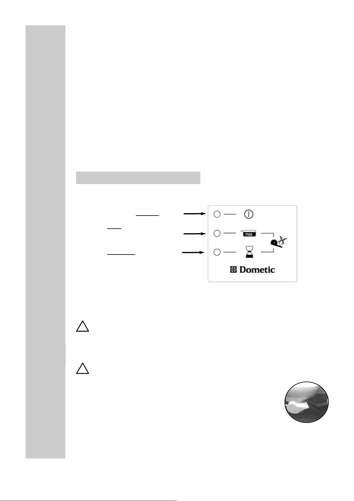
The yellow LED illuminates on the display panel.
After approx. 1 minute this procedure is finished. The green LED illuminates.
By lifting the pedal allow a little water to enter the toilet, so that the closure on
the base of the receptacle is covered.
Repeat this procedure after each flushing.
Display panel
If the cassette is full or the operating voltage is insufficient, the red LED illuminates
and the system switches off.
It cannot be used further until the cassette has been emptied or the correct
voltage has been restored.
Flushing the toilet
The toilet may only be flushed whilst the green LED is illuminated.
To flush, press the pedal down on the left side of the toilet. During the
flushing process close the seat lid; this will considerably reduce the
noise.
In order to be able to use the toilet as often as possible for one cassette
filling, please economize on the water and paper. Normally approx. 0.4 L water
are sufficient for flushing once.
5
YELLOW (pump is running), do not use toilet
GREEN (ready)
RED
(cassette full, or
undervoltage, toilet cannot be used)
The system is ready for operation!
55..00
5.1
LED
5.2
Page 6

Only use commercially available toilet paper with 2 layers.
Since the system always operates under a vacuum and is closed
hermetically, no smell can develop.
Never press the pedal whilst sitting on the toilet or if the
seat lid is open!
For the environment's sake, do not use
any chemicals.
Do not dispose any solid or non-dissolving objects
such as plastic cans or paper towels in the toilet. These
items can cause damage or plugging of the system !
Removing the cassette
To remove the cassette, raise the locking latch (A) underneath the grip.
Pull out the the cassette using the carrying grip (B).
When inserting the cassette again,
make sure that it is inserted exactly
in the opening provided and that
after pushing it in, the locking latch
has notched again.
Cleaning
Since the toilet receptacle is made of ceramic material, you can clean it in the same
way as a household toilet.
For cleaning the plastic parts (such as the lid, seat, outer
covering) please only use water with a mild cleaning
agent.If possible, rinse the cassette with fresh water
each time it has been emptied.
To avoid deposits clean also the flush ball (Fig.1) and
the sealing ring (Fig. 2 with the flush ball opened)
Occasional clean the area where the excrements are transferred at the connection
(Fig. 3) and on the base station
(Fig. 4-5).
5.3
5.4
6
A
A
B
3
4
5
1
2
For
emptying
open here
Page 7

Changing the filter
The filter in the base station must be changed according to the number of times it has
been used, at the latest, however, after three years.
Putting out of operation
If the vehicle is not going to be used for a longer period of time, especially in the
winter months, proceed according to the following instructions:
1. After the water tank has become empty in the normal way, or the vehicle pump is
switched off and the green lamp indicating "ready" for operation illuminates, press the
pedal without allowing any water to enter.
2. Repeat this procedure a second time.
3. Then empty and clean the cassette.
4. Insert the cassette again and turn off the power supply.
5. The inlet valve for the water flushing (located underneath the pedal) must
be emptied (see Fig. below).
7
5.5
Ventil
Unscrew the lock nut and
press the pedal with the
water feed turned off.
The water escapes from the
valve.
Then screw on the lock nut
again.
5.4.1
Remove the cover
filter
Page 8

Declaration of conformity5.6
8
Page 9

Page 10

INSTALLATION
The vacuum toilet is intended for installation in caravans or motor homes.
Delivery includes:
Fixation of the rear wall of the base station
66..00
6.1
10
The base plate and the rear wall must be assembled on the same vehicle element!
Toilet
Vacuum cassette Base station (complete with
base plate and rear wall)
Display panel with connection cable
1 cap
4 screws and caps
1. The rear wall of the base station is mounted on a level floor at right angles to the
outer door using all 4 screws.
The floor must be strong enough to support the weight of the cassette.
back
front
Page 11

Fixation of the floor plate of the base station
Fixation of the toilet
Inserting the cassette
11
6.2
1. The floor plate of the base station is fixed to the rear
wall.
The floor has two lugs (A), that have to be pushed
into the respective gaps in the rear wall of the base
station.
Make sure that the connection (B) for the carbon
filter fits into the place provided!
2. The floor plate of the base station is screwed to the
floor of the vehicle.
3. The ventilation hose (C) is conducted through the
vehicle floor to the exterior.
1. The toilet must be installed horizontally. .
2. Use the screws included in the delivery for fastening it
to the floor of the vehicle.
3. The screws are then covered with the four caps.
The floor and the cassette are in dovetail design.
The cassette can easily be pushed into this opening until the lock in the groove (D) notches.
6.3
6.4
Distance to the rear
wall : min. 50 mm
A
A
B
C
D
C
Page 12

Connecting pipes6.5
- The installation of the connecting pipes (DN 40) from the vacuum cassette
to the toilet must be completely airtight and include a siphon!
- The maximum length of the pipes from the toilet to the cassette is
approx. 7 m!
- If the pipes have to be shortened for laying purposes, the place where it is
sawn must be deburred and the pipes chamfered from the outside.
- The laid pipes must be fastened without any strain with a pipe clip (40x15)
approx. every 0.8 m.
- The maximum difference in height of the pipe connections from the toilet to
the cassette must not exceed 0.8 m (see Fig. 1).
Always lay the pipes at right angles!
- The horizontally laid pipes must be installed with an incline of approx. 1°
from the toilet to the cassette (see Fig. 1)!
Correct
installation!
Wrong
installation!
12
Fig. 1
Fig. 2
Fig. shows the complete VT 2500 system
siphon
siphon
LED-display panel
with pipe connection on the right-hand side (pipe connection on the left-hand side, optional)
Page 13

Water supply
Electrical installation
Electrical installation must be carried
out by qualified personnel only !
The 12V DC connection to the toilet electronics is shown in the adjacent figure.
The 2-pole connection cable is connected to
the electronics as shown in the figure.
The connection cable must have a crosssection of at least 4 mm².
The connection cable must be protected by
an 8 amp fuse. The connection should be
made directly to the board battery.
The board battery should be protected by an
undervoltage cut-out.
.
Connection display on the control electronics
6.6
The water supply is provided with
the aid of a pump (this can also be
the pump available in the vehicle)
and a hose connection from the
fresh-water container.
Fasten a hose clamp to the water-supply connection.
6.7
red
(+12V)
white
(ground)
6.7.1
13
display panel
4-strand, coded connection cable
electronic board
electronic board
The 4-strand, coded connection cable (A)
(cable cross-section 1 mm²) is connected to
the circuit board as shown in the figures.
A
A
base station
Page 14

Microswitch connection
Data sheet
Voltage supply: 12 V direct current,
Undervoltage fuse to be provided for on the vehicle.
Current consumption: 1.5 A whilst the pump is running
Pump running time: max. 60-70 sec. (depending on cassette content
and length of pipes laid)
Total cassette content: approx. 25 litres
Of this cassette content,
excrements: approx. 14 litres
Chemical additives: not required
Toilet paper: use with a max. of 2 layers
Changing the filter: depending on frequency used, at the latest every
3 years.
Dimensions: toilet
420 x 350 x 430
(H x W x D in mm) base station with container 302 x 269 x 548
6.8
14
6.7.2
For vehicles that are not equipped with a pressurized water system, a toilet with integrated
microswitch for controlling a pump must be
installed.
The microswitch (A) is connected in the circuit of
the submergible pump so that the pump is activated via the microswitch when the pedal is pressed.
Connection cable to the
pump with two wires
A
This connection is not necessary in vehicles with a pressure controlled pump.
area for siphon and pipes depending on builtin-situation (ch. 6.5)
Page 15

Wiring diagram6.9
15
The power supply must comply with the following performance data:
Vehicle battery:
Voltage > 11.5 Volt
Peak current (short-term) 8 Amp. Use slow-acting fuse in the feed line!
These values are reached in the standard vehicle batteries.
Power pack:
When using a controlled fixed-voltage power pack (e.g. for application in weekend homes) one
should similarly make sure that these values are adhered to. Normal rated voltage for power
packs with 13.8 V at 6 A.
The control electronics are equipped with an overload protection (Poly Switch). This fuse protects
the motor against excessively high currents (e.g. also for older or badly serviced batteries, that
supply less than the required minimum voltage of 11.5 Volt ). Should this fuse be activated (red
LED illuminates on the control display), it is necessary to check the power supply and ensure that
the given values are adhered to.
After a RESET (short-term interruption of the electric circuit, e.g. by removing the cassette) and a
short cooling-down period (approx. 1 min) the system is ready for .
Page 16

Dometic GmbH
In der Steinwiese 16
D-57074 Siegen
Tel.: +49-(0) 271 / 692-0
Fax.: +49-(0) 271 / 692 - 300
www.dometic.de/caravan
Dometic AB
Torggatan 8
S-17154 Solna
Tel.: +46- 8 501 025 00
Fax.: +46- 8 501 025 98
www.dometic.com
© Dometic GmbH - 2002 - Subject to change without notice - Printed in Germany
 Loading...