

Page 1
2004-05-12 Vers. 1.0 / 2011
MBA 02/2011
N 8
Bedienungsanleitung
Dometic Schaltnetzteile 230V/12V für Freizeitfahrzeuge
Dometic converters 230V/12V for recreational vehicles
Dometic convertisseurs 230V/12V pour véhicules de loisirs
Dometic convertitori 230V / 12V per veicoli ricreazionali
Dometic omvormer 230V / 12V voor recreatievoertuigen
& Installationsanleitung
EN
DE
IT
NL
FR
Type I Type II
Schaltnetzteile für Freizeitfahrzeuge
Page 2

© Dometic Light Systems GmbH - 2011 - Änderungen vorbehalten
2
Dometic Light Systems GmbH
Dillenburger Straße 59
D-35685 Dillenburg
www.dometic.com
Deutsch . . . . . . . . . . . . . . . . . . . . . . . . . . . . . . . . . . . . . . . . . . . . . . . . . . . 3
English . . . . . . . . . . . . . . . . . . . . . . . . . . . . . . . . . . . . . . . . . . . . . . . . . . . . 9
Français . . . . . . . . . . . . . . . . . . . . . . . . . . . . . . . . . . . . . . . . . . . . . . . . . . 15
Italiano . . . . . . . . . . . . . . . . . . . . . . . . . . . . . . . . . . . . . . . . . . . . . . . . . . . 21
Nederlands . . . . . . . . . . . . . . . . . . . . . . . . . . . . . . . . . . . . . . . . . . . . . . . . 27
Page 3

3
1.0 Allgemeines . . . . . . . . . . . . . . . . . . . . . . . . . . . . . . . . . . . . . . . . . . . 4
1.1 Produktbeschreibung und Verwendung . . . . . . . . . . . . . . . . . . . . . . . . . . . . . . . . . . . . . . . . . . . 4
1.2 Hinweise zu dieser Bedienungsanleitung . . . . . . . . . . . . . . . . . . . . . . . . . . . . . . . . . . . . . . . . . 4
1.3 Urheberschutz . . . . . . . . . . . . . . . . . . . . . . . . . . . . . . . . . . . . . . . . . . . . . . . . . . . . . . . . . . . . . . 4
1.4 Erklärung der verwendeten Symbole . . . . . . . . . . . . . . . . . . . . . . . . . . . . . . . . . . . . . . . . . . . . . 4
1.5 Gewährleistung . . . . . . . . . . . . . . . . . . . . . . . . . . . . . . . . . . . . . . . . . . . . . . . . . . . . . . . . . . . . . 5
1.6 Haftungsbeschränkung . . . . . . . . . . . . . . . . . . . . . . . . . . . . . . . . . . . . . . . . . . . . . . . . . . . . . . . 5
2.0 Sicherheitshinweise . . . . . . . . . . . . . . . . . . . . . . . . . . . . . . . . . . . . . 5
2.1 Bestimmungsgemäße Verwendung . . . . . . . . . . . . . . . . . . . . . . . . . . . . . . . . . . . . . . . . . . . . . . 5
2.2 Verantwortung des Nutzers . . . . . . . . . . . . . . . . . . . . . . . . . . . . . . . . . . . . . . . . . . . . . . . . . . . . 5
3.0 Bedienung des AC/DC-Wandlers . . . . . . . . . . . . . . . . . . . . . . . . . . 6
3.1 Einschalten . . . . . . . . . . . . . . . . . . . . . . . . . . . . . . . . . . . . . . . . . . . . . . . . . . . . . . . . . . . . . . . . . 6
3.2 Schutzeinrichtungen . . . . . . . . . . . . . . . . . . . . . . . . . . . . . . . . . . . . . . . . . . . . . . . . . . . . . . . . . . 6
3.2.1 Übertemperaturschutz . . . . . . . . . . . . . . . . . . . . . . . . . . . . . . . . . . . . . . . . . . . . . . . . . . . . . . . . . . . . . . . . 6
3.2.2 Überlastschutz und Kurzschluss . . . . . . . . . . . . . . . . . . . . . . . . . . . . . . . . . . . . . . . . . . . . . . . . . . . . . . . . 6
3.2.3 Überspannungsschutz . . . . . . . . . . . . . . . . . . . . . . . . . . . . . . . . . . . . . . . . . . . . . . . . . . . . . . . . . . . . . . . . 7
3.2.4 Sicherungen . . . . . . . . . . . . . . . . . . . . . . . . . . . . . . . . . . . . . . . . . . . . . . . . . . . . . . . . . . . . . . . . . . . . . . . . 7
3.3 Maßnahmen bei Störungen . . . . . . . . . . . . . . . . . . . . . . . . . . . . . . . . . . . . . . . . . . . . . . . . . . . . 7
4.0 Installation . . . . . . . . . . . . . . . . . . . . . . . . . . . . . . . . . . . . . . . . . . . . 8
4.1 Einbau . . . . . . . . . . . . . . . . . . . . . . . . . . . . . . . . . . . . . . . . . . . . . . . . . . . . . . . . . . . . . . . . . . . . 8
4.1.1 Vertikaler Einbau . . . . . . . . . . . . . . . . . . . . . . . . . . . . . . . . . . . . . . . . . . . . . . . . . . . . . . . . . . . . . . . . . . . . . 8
4.1.2 Horizontaler Einbau . . . . . . . . . . . . . . . . . . . . . . . . . . . . . . . . . . . . . . . . . . . . . . . . . . . . . . . . . . . . . . . . . . 8
5.0 Technische Daten . . . . . . . . . . . . . . . . . . . . . . . . . . . . . . . . . . . . . . 33
5.1 Type I . . . . . . . . . . . . . . . . . . . . . . . . . . . . . . . . . . . . . . . . . . . . . . . . . . . . . . . . . . . . . . . . . . . . . 33
5.2 Type IIa . . . . . . . . . . . . . . . . . . . . . . . . . . . . . . . . . . . . . . . . . . . . . . . . . . . . . . . . . . . . . . . . . . . . 34
5.3 Type IIb . . . . . . . . . . . . . . . . . . . . . . . . . . . . . . . . . . . . . . . . . . . . . . . . . . . . . . . . . . . . . . . . . . . . 35
6.0 Tabelle . . . . . . . . . . . . . . . . . . . . . . . . . . . . . . . . . . . . . . . . . . . . . . . 36
Inhaltsverzeichnis
Deutsch
Page 4
4
1.0 Allgemeines
Dometic AC/DC-Wandler werden zur
Versorgung von 12V-Geräten im Permanentbetrieb eingesetzt. Die Eingangsspannung
kommt dabei entweder von der 230VWechselstromnetzversorgung oder einer 12VGleichstromquelle, wobei die 230VWechselspannung Vorrang hat.
1.1 Produktbeschreibung und
Verwendung
Die Angaben, Texte und Abbildungen in dieser
Anleitung sind urheberrechtlich geschützt und
unterliegen den gewerblichen Schutzrechten.
Kein Teil dieser Anleitung darf ohne die schriftliche Genehmigung der Dometic Light
Systems GmbH, , reproduziert, kopiert oder
sonstwie verwendet werden.
1.3 Urheberschutz
Bevor Sie den AC/DC-Wandler nutzen,
lesen Sie die Bedienungsanleitung bitte
sorgfältig durch.
Diese Anleitung gibt Ihnen die nötigen
Hinweise für den richtigen Gebrauch des
AC/DC-Wandlers. Beachten Sie besonders
die Sicherheitshinweise. Die Einhaltung der
Hinweise und Handlungsanweisungen ist
wichtig für den sicheren Umgang mit Ihrem
AC/DC-Wandler und schützt Sie und den
AC/DC-Wandler vor Schäden. Das Gelesene
muss verstanden worden sein, bevor Sie eine
Maßnahme durchführen.
Bewahren Sie diese Bedienungsanleitung
sorgfältig in der Nähe des Gerätes auf,
sodass sie jederzeit verwendet werden
kann.
1.2 Hinweise zu dieser
Bedienungsanleitung
1.4 Erklärung der verwendeten
Symbole
Allgemeines
Warnhinweise sind durch Symbole gekennzeichnet. Ein ergänzender Text erläutert Ihnen
den Grad der Gefährdung.
Beachten Sie diese Warnhinweise sehr
genau. Damit schützen Sie sich, andere
Personen und das Gerät vor Schäden.
Warnhinweise
Information
WARNUNG kennzeichnet eine mögliche
Gefahrensituation, die zum Tod oder einer ernsten Verletzung führen kann, wenn die angegebenen Anweisungen nicht befolgt werden.
WARNUNG!
VORSICHT kennzeichnet eine mögliche
Gefahrensituation, die zu leichten oder mittleren Verletzungen führen kann, wenn die angegebenen Anweisungen nicht befolgt werden.
VORSICHT!
INFORMATION gibt Ihnen ergänzende und
nützliche Hinweise zum Umgang mit dem
Gerät.
VORSICHT ohne Sicherheitssymbol kennzeich-
net eine mögliche Gefahrensituation, die zu
Beschädigungen des Gerätes führen kann,
wenn die angegebenen Anweisungen nicht
befolgt werden.
VORSICHT!
Page 5

5
Sicherheitshinweise
Gewährleistungsabwicklungen erfolgen nach
der europäischen Richtlinie 44/1999/EC und
den landesüblichen Bedingungen. Störungen,
die auf fehlerhafte Bedienung zurückzuführen
sind, unterliegen nicht der Gewährleistung.
1.5 Gewährleistung
Alle Angaben und Hinweise in dieser
Bedienungsanleitung wurden unter
Berücksichtigung geltender Normen und
Vorschriften sowie dem Stand der Technik
erstellt. Dometic behält sich vor, jederzeit
Änderungen am Produkt vorzunehmen, die im
Interesse der Verbesserung des Produktes
und der Sicherheit angebracht sind.
Dometic übernimmt keine Haftung für
Schäden bei :
Nichtbeachtung der Bedienungsanleitung
nicht bestimmungsgemäßer Verwendung
Verwendung von nicht originalen
Ersatzteilen
Veränderungen und Eingriffen am Gerät
Einwirkung von Umgebungseinflüssen, wie
- Temperaturänderungen
- Luftfeuchtigkeit
1.6 Haftungsbeschränkung
Dometic AC/DC-Wandler werden zur
Versorgung von 12V-Geräten im Permanentbetrieb eingesetzt.
2.1 Bestimmungsgemäße
Verwendung
Personen, die den Dometic AC/DC-Wandler
bedienen, müssen mit dem sicheren Umgang
vertraut sein und die Hinweise dieser
Bedienungsanleitung kennen.
Eine Nichtbeachtung der folgenden Sicherheitshinweise kann zu ernsten Beschädigungen des Dometic AC/DC-Wandlers und der
angrenzenden Bereiche führen.
2.2 Verantwortung des Nutzers
2.0 Sicherheitshinweise
Nehmen Sie keine Änderungen, zusätzliche Installationen oder Reparaturen am
Dometic AC/DC-Wandler oder an der vom
Fahrzeughersteller ausgeführten Installation vor.
WARNUNG!
Der Dometic AC/DC-Wandler darf nicht in
Bereichen eingesetzt werden, in denen
Gas- oder Staubexplosionsgefahr
besteht.
WARNUNG!
Der Dometic AC/DC-Wandler darf weder
abgedeckt noch Umgebungsbedingungen
ausgesetzt sein, die die Belüftung der
Einheit beeinträchtigen.
VORSICHT!
Page 6
6
Bedienung
3.1 Einschalten
Geräte vom Typ 1 (siehe Abb. 4, S. 33) las-
sen sich über den ON/OFF Schalter einund ausschalten. Bei grün aufleuchtender
LED unterhalb des ON/OFF-Schalters sind
230VAC-Eingangsspannung verfügbar.
Leuchtet die grüne LED nicht auf, liegt
keine 230V AC-Eingangsspannung an der
Einheit an, oder das Gerät hat durch Überhitzung abgeschaltet (siehe Pkt. 3.2.1).
Geräte vom Typ 2 a + b ( Abb. 5 und 6, S.
34 und 35) schalten sich ein, sobald 230V
Spannung am Anschluss zur Verfügung
steht.
Die Verbraucher können unabhängig vom
230V Betrieb über eine 12V DC-Energiequelle (z. B. Batterie) versorgt werden,
sofern diese mit dem Wandler verbunden
ist. Die interne Vorrangschaltung trennt
die 12VDC - Energiequelle automatisch,
sobald 230VAC anliegen. Der AC/DC
Wandler ist kein Ladegerät.
3.2 Schutzeinrichtungen
Bei einer Überhitzung der Einheit löst der
thermische Überlastschutz aus. Zum
Wiedereinschalten trennen Sie den Wandler
vom 230VAC- Netz Leitungsschutzschalter
auf OFF oder 230VAC Zuleitung zum
Fahrzeug abziehen ).
230V
AC Versorgung
Sobald der Leitungsschutzschalter (im vorgeschalteten Sicherungskasten ) in ON
Position ist und eine 230VAC Spannungsquelle am Fahrzeug angeschlossen wurde,
ist der AC/DC Wandler betriebsbereit.
12VDC V
ersorgung
Stehen die 230VAC nicht zur Verfügung,
aber am AC/DC Wandler ist eine 12VDC
Energiequelle ( z. B. Batterie ) angeschlossen, so werden die Verbraucher hierüber
versorgt.
Sollte der thermische Überlastschutz wie-
derholt auslösen und das Gerät abschalten, liegt die Ursache möglicherweise an
einer unzureichenden Belüftung. Ist dies
der Fall, sorgen Sie für eine bessere
Belüftung und starten Sie die Einheit
erneut.
Wenn danach der thermische Überlast-
schutz immer noch anspricht, nehmen Sie
bitte Kontakt zu einem autorisierten
Dometic Servicepartner auf.
3.2.1 Übertemperaturschutz
Zu Ihrer Sicherheit sind Dometic AC/DCWandler mit verschiedenen Schutzfunktionen
ausgestattet.
3.0 Bedienung des
AC/DC-Wandlers
Der Überlastschutz spricht unter folgenden
Voraussetzungen an:
Bei mäßiger Überlast, die mit zunehmender
Betriebsdauer zu hohe Innentemperaturen
führt und in der Folge den oben genannten
thermischen Überlastschutz auslöst.
Dadurch sinkt die Ausgangsspannung, und
der Unterspannungsschutz löst aus.
Die Einheit ist mit einer internen Kurz-
schlussüberwachung ausgestattet.
Sobald ein voreingestellter Wert erreicht ist,
löst dieser Schutz aus und schaltet die
Einheit ab, ohne dass Sicherungen durch
brennen. In diesem Fall ist Vorsicht geboten.
3.2.2 Überlastschutz und Kurzschluss
Beachten Sie, dass über die Geräte aufgrund
der gerätespezifischen hohen Leistung hohe
Ströme fließen, obwohl sie nur eine 12V
Spannung erzeugen.
Achten Sie unbedingt darauf, dass die
Leistung der an dem jeweiligen Ausgang
angeschlossenen Verbraucher den Vorgaben
unter Punkt 3.2.4 entsprechen.
Änderungen an der Installation dürfen nur
durch autorisierte Fachkräfte in Abstimmung
mit dem Fahrzeughersteller durchgeführt werden.
Page 7
7
Bedienung
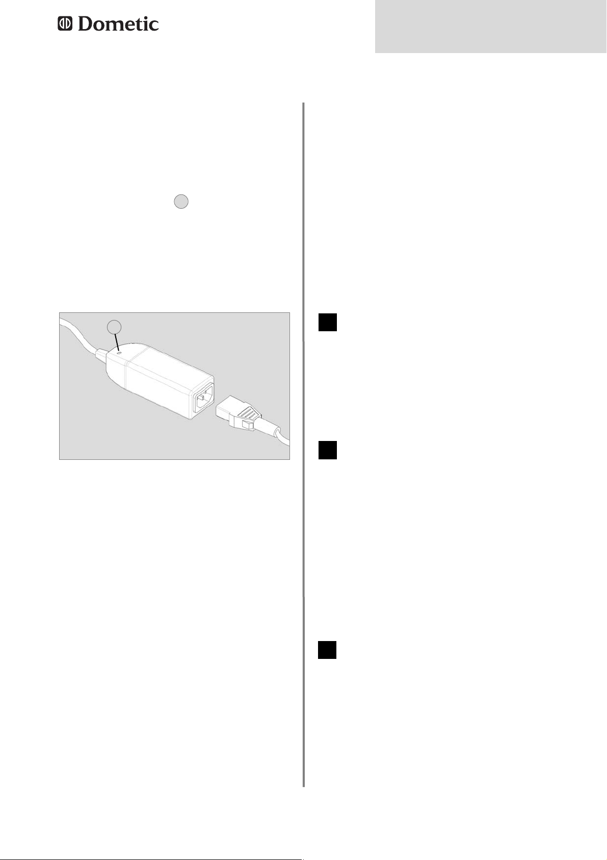
Abb. 1
Der Dometic Überspannungsschutz (OVPunit, Abb. 1) wird dem Schaltnetzteil vorgeschaltet. Er trennt die Zuleitung, wenn die
Eingangsspannung ca. 270 V~ überschreitet.
Angeschlossene Geräte werden geschützt.
Eine rote Leuchtdiode (1) zeigt an, dass eine
Überspannung angelegen hat.
Der Dometic Überspannungsschutz setzt sich
selbst zurück, wenn die Spannung wieder
einen normalen Pegel erreicht hat. Die LED
leuchtet noch 20 bis 30 Minuten, nachdem die
Spannung wieder einen sicheren Pegel
erreicht hat.
3.2.3 Überspannungsschutz
Die Netzteile können mit unterschiedlichen
Sicherungen bestückt sein.
Bei der Installation ist unbedingt darauf zu
achten, dass die an den einzelnen
Sicherungen abgenommene Leistung max. 75
% des Nennwertes der jeweiligen Sicherung
betragen darf. Höhere Leistungen können aufgrund des höheren Stromes zu Überhitzung
und zu einer Beschädigung führen.
Eine defekte Sicherung deutet in der Regel auf
einen Kurzschluss oder eine Überlast des 12
V-Ausgangs hin. Dies wird durch eine rot aufleuchtende LED neben der Sicherung signalisiert (siehe Abb. 2) wenn ein Verbraucher
angeschlossen ist.
Eine fehlende Sicherung im Sicherungshalter
wird auch nur bei angeschlossenem
Verbraucher angezeigt. Versuchen Sie im Falle
einer defekten Sicherung die Ursache im 12 V
3.2.4 Sicherungen
Die 230 V und 12 V Ausgänge werden im
Netzbetrieb nicht versorgt, die grüne
LED leuchtet nicht.
a. Prüfen Sie, ob die Netzverbindung
getrennt wurde, ggf. diese wiederherstellen. Prüfen Sie, ob der Sicherungsautomat
abgeschaltet hat.
3.3 Maßnahmen bei Störungen
1
1
12 V Ausgänge werden im Netzbetrieb
nicht versorgt.
a. Prüfen Sie die 12 Volt Stecksicherungen,
defekte Sicherungen werden durch d i e
rote LED angezeigt. Ersetzen Sie ggf. die
Sicherungen gegen eine neue Sicherung
gleichen Typs und Stromstärke.
b. Prüfen Sie, ob das Gerät durch Überhitzung abgeschaltet hat, die grüne LED
leuchtet nicht. Schalten Sie das Gerät aus
und warten Sie ca. 2 Minuten, bevor Sie
das Gerät wieder einschalten.
2
12 V Ausgänge werden im Batteriebetrieb nicht versorgt.
a. Prüfen Sie die 12 Volt Stecksicherungen,
defekte Sicherungen werden durch die rote
LED angezeigt. Ersetzen Sie ggf. die
Sicherungen gegen eine neue Sicherung
gleichen Typs und Stromstärke.
b. Prüfen Sie die Batterie und deren
Anschluss an dem Umformer.
3
Stromkreis zu lokalisieren und nach
Möglichkeit zu beheben. Schalten Sie vor
Austausch der Sicherung den AC/DCWandler aus, oder trennen das Gerät von der
230VAC Versorgung. Ersetzen Sie eine defekte Sicherung ausschließlich durch eine neue
Sicherung des Typs ATO Type - LITTLEFUSE.
Schalten Sie die Einheit wieder ein (siehe Abb.
4). Sollte die Sicherung erneut auslösen, wenden Sie sich bitte an einen Servicepartner für
Dometic AC/DC-Wandler.
1
Page 8
8
Installation
4.0 Installation
Installieren Sie den AC/DC-Wandler an
einer gut belüfteten und vor Feuchtigkeit
geschützten Stelle. Um eine optimale
Wärmeableitung zu erreichen, muss das
Gerät vertikal (siehe Abb. 2) montiert werden.
Halten Sie bei der Installation die angege-
benen Abstände ein.
In diesem Bereich dürfen sich keine
leicht entflammbaren Stoffe wie Textilien,
Papier etc. befinden.
Achten Sie darauf, dass die Luftzirkulation
weder durch Abdeckungen noch durch
andere störende Einflüsse behindert wird.
Der AC/DC Wandler kann nur mit sinusför-
miger Netzspannung ( 230VAC ) betrieben
werden. Liefert ein Generator diese
Spannung, so sollte ein Überspannungsschutz dem Netzteil vorgeschaltet werden.
4.1 Einbau
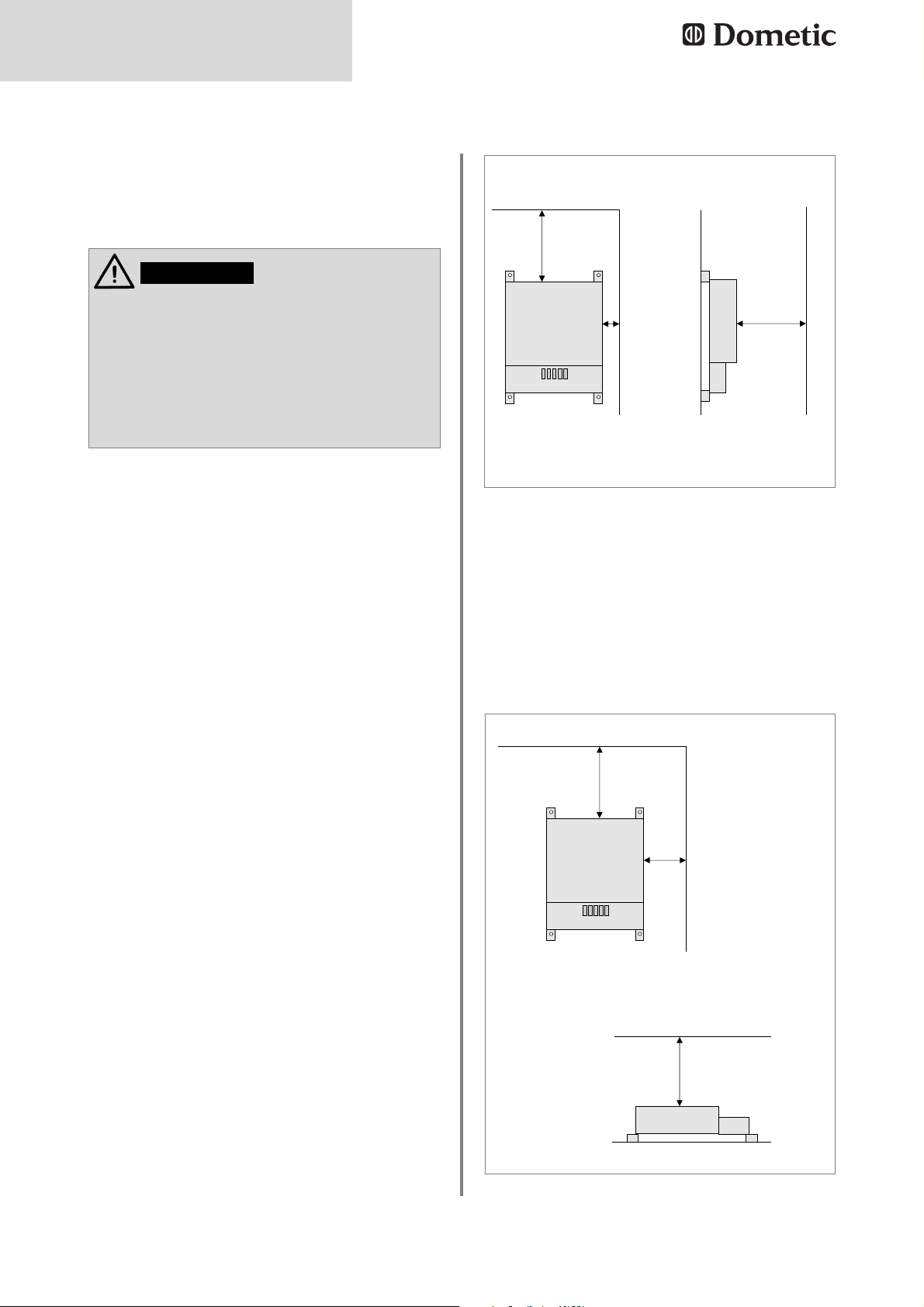
4.1.1 Vertikaler Einbau
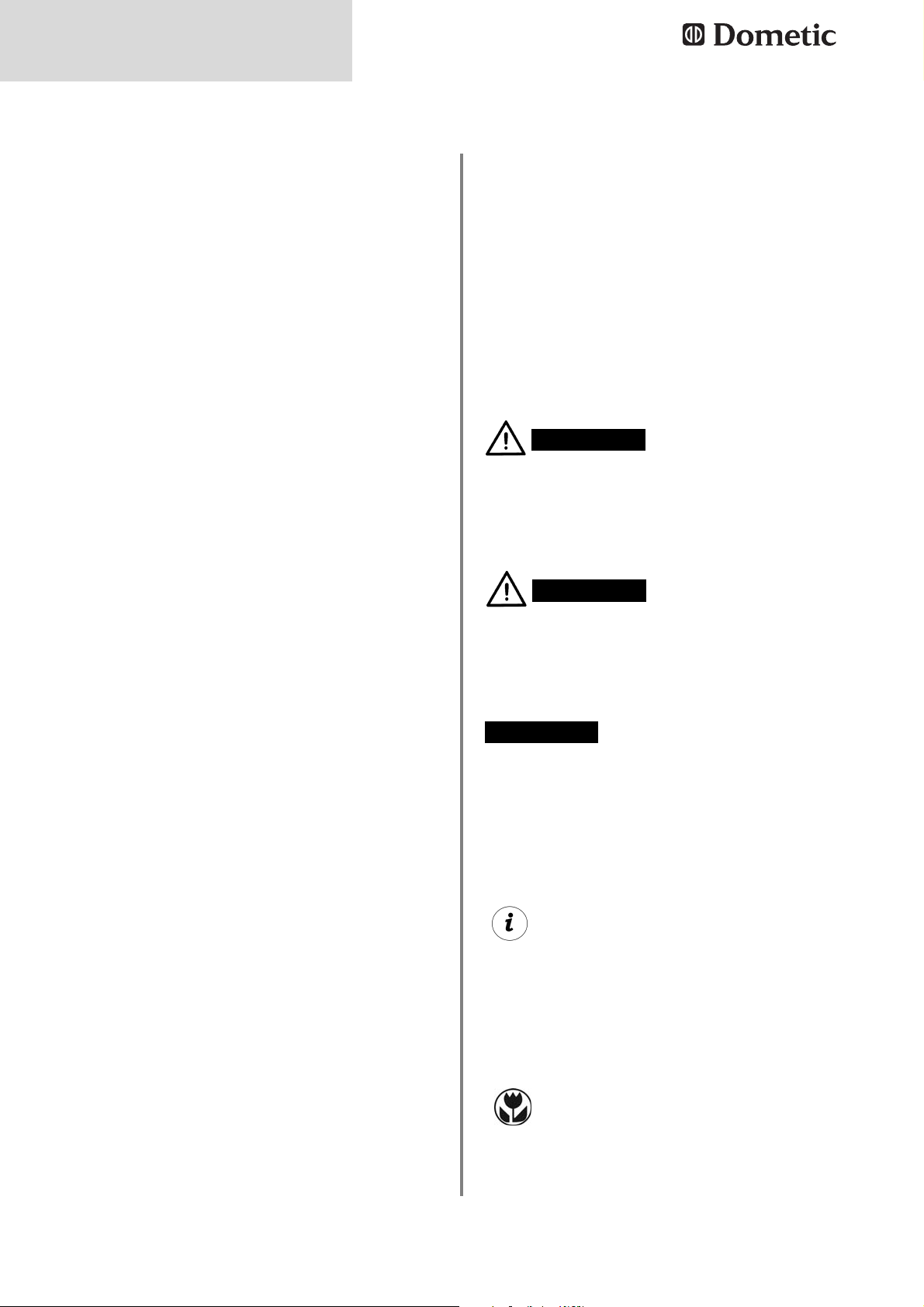
4.1.2 Horizontaler Einbau
A: Wand
B: Seitenwand
C: Decke
D: Boden / Podest
E: min 200mm Distanz oberhalb des Netzteils
einhalten.
Der optimale Einbau des AC/DC-Wandlers ist
in vertikaler Position (Abb 2). Die maximale
Umgebungstemperatur darf 50°C betragen.
Die zweite Möglichkeit, den AC/DC-Wandler
zu installieren, ist der horizontale Einbau auf
dem Boden oder einem Podest.
Die maximale Umgebungstemperatur darf nur
40°C betragen.
(40-50°C ok bei maximal 75% Last)
Abb. 2
Dometic AC/DC-Wandler werden vom
Fahrzeughersteller fest eingebaut und
angeschlossen. Es ist unzulässig, Kabel
an die Einheit anzuschließen bzw. von dieser zu entfernen oder die Installation
anderweitig zu modifizieren.
WARNUNG!
Abb. 3
E
A
C
E
B
D
B
B
C
min 200mm
B
Power transformer
Power transformer
E
min 50mm
min 200mm
E
B
B
min 100mm
D
min 200mm
Power transformer
E
E
mm
min 200mm
Power transformer
Page 9

9
English
1.0 General . . . . . . . . . . . . . . . . . . . . . . . . . . . . . . . . . . . . . . . . . . . . . . 10
1.1 Description of product and application . . . . . . . . . . . . . . . . . . . . . . . . . . . . . . . . . . . . . . . . . . . 10
1.2 Guide to these operating instructions . . . . . . . . . . . . . . . . . . . . . . . . . . . . . . . . . . . . . . . . . . . .10
1.3 Copyright protection . . . . . . . . . . . . . . . . . . . . . . . . . . . . . . . . . . . . . . . . . . . . . . . . . . . . . . . . . 10
1.4 Explanation of symbols used in this manual . . . . . . . . . . . . . . . . . . . . . . . . . . . . . . . . . . . . . . . 10
1.5 Warranty . . . . . . . . . . . . . . . . . . . . . . . . . . . . . . . . . . . . . . . . . . . . . . . . . . . . . . . . . . . . . . . . . . . 11
1.6 Limitation of liability . . . . . . . . . . . . . . . . . . . . . . . . . . . . . . . . . . . . . . . . . . . . . . . . . . . . . . . . . . 11
2.0 Safety instructions . . . . . . . . . . . . . . . . . . . . . . . . . . . . . . . . . . . . . . 11
2.1 Application according to regulations . . . . . . . . . . . . . . . . . . . . . . . . . . . . . . . . . . . . . . . . . . . . .11
2.2 User's responsibility . . . . . . . . . . . . . . . . . . . . . . . . . . . . . . . . . . . . . . . . . . . . . . . . . . . . . . . . . . 11
3.0 Operation of the AC/DC converter . . . . . . . . . . . . . . . . . . . . . . . . . 12
3.1 Switching on . . . . . . . . . . . . . . . . . . . . . . . . . . . . . . . . . . . . . . . . . . . . . . . . . . . . . . . . . . . . . . . . 12
3.2 Safety devices . . . . . . . . . . . . . . . . . . . . . . . . . . . . . . . . . . . . . . . . . . . . . . . . . . . . . . . . . . . . . . 12
3.2.1 Overtemperature protection . . . . . . . . . . . . . . . . . . . . . . . . . . . . . . . . . . . . . . . . . . . . . . . . . . . . . . . . . . . . 12
3.2.2 Overload protection and short-circuit protection . . . . . . . . . . . . . . . . . . . . . . . . . . . . . . . . . . . . . . . . . . . . 12
3.2.3 Surge voltage protection . . . . . . . . . . . . . . . . . . . . . . . . . . . . . . . . . . . . . . . . . . . . . . . . . . . . . . . . . . . . . . 13
3.2.4 Fuses . . . . . . . . . . . . . . . . . . . . . . . . . . . . . . . . . . . . . . . . . . . . . . . . . . . . . . . . . . . . . . . . . . . . . . . . . . . . . 13
3.3 Measures in case of malfunctions . . . . . . . . . . . . . . . . . . . . . . . . . . . . . . . . . . . . . . . . . . . . . .13
4.0 Installation . . . . . . . . . . . . . . . . . . . . . . . . . . . . . . . . . . . . . . . . . . . . 14
4.1 Installation . . . . . . . . . . . . . . . . . . . . . . . . . . . . . . . . . . . . . . . . . . . . . . . . . . . . . . . . . . . . . . . . . 14
4.1.1 Vertical Installation . . . . . . . . . . . . . . . . . . . . . . . . . . . . . . . . . . . . . . . . . . . . . . . . . . . . . . . . . . . . . . . . . . . 14
4.1.2 Horizontal Installation . . . . . . . . . . . . . . . . . . . . . . . . . . . . . . . . . . . . . . . . . . . . . . . . . . . . . . . . . . . . . . . . . 14
5.0 Technical Data . . . . . . . . . . . . . . . . . . . . . . . . . . . . . . . . . . . . . . . . . 33
5.1 Type I . . . . . . . . . . . . . . . . . . . . . . . . . . . . . . . . . . . . . . . . . . . . . . . . . . . . . . . . . . . . . . . . . . . . . 33
5.2 Type IIa . . . . . . . . . . . . . . . . . . . . . . . . . . . . . . . . . . . . . . . . . . . . . . . . . . . . . . . . . . . . . . . . . . . . 34
5.3 Type IIb . . . . . . . . . . . . . . . . . . . . . . . . . . . . . . . . . . . . . . . . . . . . . . . . . . . . . . . . . . . . . . . . . . . . 35
6.0 Table . . . . . . . . . . . . . . . . . . . . . . . . . . . . . . . . . . . . . . . . . . . . . . . . 36
Table of content
Page 10
10
General
1.0 General
Dometic AC/DC converters are used for the
power supply of 12 V appliances in continuous
operation. The input voltage thereby comes
either from the 230 V AC mains power supply
(Priority 230VAC) .
1.1 Description of product and
application
The information, texts and illustrations in these
instructions are copyright protected and are
subject to industrial property rights. No part of
these instructions may be reproduced, copied
or used in any other way without written authorisation by Dometic Light Systems GmbH,
Dillenburg.
1.3 Copyright protection
Read the operating instructions carefully
before you use the AC/DC converter.
These instructions provide you with the necessary guidance for the proper use of your
AC/DC-converter. Observe in particular the
safety instructions. Compliance with the
instructions and handling recommendations is
important for dealing with the AC/DC-converter safely and for protecting you from injury
and the appliance from damage. You must
understand what you have read before you
carry out a task.
Keep this operating manual carefully and
ready to hand so that it can be used at any
time.
1.2 Guide to these operating
instructions
1.4 Explanation of symbols
used in this manual
Warning notices are identified by symbols. A
supplementary text gives you an explanation
of the degree of danger.
Observe these warning notices rigorously.
You will thus protect yourself and other
people from injury, and the appliance from
damage.
Warning notices
Information
WARNING indicates a potentially hazardous
situation which could result in death or serious
injury if the given instructions are not adhered
to.
WARNING!
CAUTION indicates a potentially hazardous
situation which can result in minor or moderate injury if the given instructions are not adhered to
CAUTION!
INFORMATION gives you supplementary and
useful guidance for dealing with your refrigerator.
Environmental tips
ENVIRONMENTAL TIPS give you useful gui-
dance for saving energy and disposal of the
appliance.
CAUTION (used without the safety alert sym-
bol) indicates a potentially hazardous situation
which can result in damage to the appliance if
the given instructions are not adhered to.
CAUTION!
Page 11
11
Safety instructions
Warranty arrangements are in accordance
with EC Directive 44/1999/CE and the normal
conditions applicable for the country concerned. Any damage due to improper use is not
covered by the warranty.
1.5 Warranty
All information and guidance in these operating instructions were prepared after taking
into consideration the applicable standards
and regulations as well as the current state of
the art. Dometic reserves the right to make
changes at any time which are deemed to be
in the interest of improving the product and
safety.
Dometic will assume no liability for damage in
the case of :
non-observation of the operating instructi-
ons
application not in accordance with the
regulations or provisions
use of non-original spare parts
modifications and interferences to the
appliance
effect of environmental influences, such as
- temperature fluctuations
- humidity
1.6 Limitation of liability
Dometic AC/DC converters are used for the
power supply of 12 V appliances in continuous
operation.
2.1 Application according to
regulations
Anyone operating the Dometic AC/DC converters must be familiar with the safe handling
and understand the instructions in this operating manual.
Non-observance of the following safety
instructions can result in serious damage to
the Dometic AC/DC converter and adjacent
areas.
2.2 User's responsibility
2.0 Safety instructions
Do not make any changes to or additional
installations at the Dometic AC/DC converter or to the installation performed by
the vehicle manufacturer.
WARNING!
The Dometic AC/DC converter must not
be used in potentially explosive gas or
dust areas.
WARNING!
The Dometic AC/DC converter must not
be covered or exposed to environmental
conditions which adversely affect the
ventilation of the unit.
CAUTION!
Page 12
12
Operation
3.1 Switching on
Devices of the type 1 (see Fig. 4page 33)
can be switched on and off using the
On/Off switch. 230 V AC input voltage is
available when the LED under the ON/OFF
switch is lit green. If the green LED does not
light, there is no 230 V AC input voltage
present at the unit or the device has switched off due to overheating (see point
3.2.1).
Devices of the types 2 a + b switch on as
soon as 230 V voltage is available at the
connection.
The consumers can be supplied with power
independently of the 230 V operation using
a 12 V DC energy source (e.g. battery) if this
is connected to the converter. The internal
priority circuit disconnects the 12 V DC
energy source automatically as soon as
230 V AC is present. The AC/DC converter
is not a charger.
3.2 Safety devices
The thermal overload cut-out trips in the
case of the unit overheating. To reactivate
the unit, first switch it OFF. Wait for at least
60 seconds before restarting the system.
230V
AC supply
As soon as the circuit breaker (in the fuse
box) is in the ON position and the vehicle is
connected to a 230V AC power supply, the
AC/DC converter is ready for operation.
12VDC supply
If no 230V AC supply is available, a 12V DC
power source (e.g. battery) can be connected to the AC/DC converter; the consumers
will then be supplied from this source.
If the thermal overload cut-out trips again
and switches off the appliance, the cause
may be insufficient ventilation. If this is the
case, provide better ventilation and restart
the unit.
If the thermal overload cut-out still trips
afterwards, please contact an authorised
Dometic service partner.
3.2.1 Overtemperature protection
Dometic AC/DC converters have various
safety functions for your safety.
3.0 Operation of the
AC/DC converter
The overload cut-out trips under the following
conditions:
In the case of moderate overload which
results in high internal temperatures with
increasing operation duration and then trips
the overload cut-out mentioned above. This
reduces the output voltage and the under
voltage cut-out trips.
The unit is equipped with internal short-cir-
cuit monitoring. As soon as a preset value
is reached, this cut-out trips and switches
off the unit without blowing fuses. Caution
is required in this case.
3.2.2 Overload protection and short-cir
cuit protection
Note that high currents flow over the units due
to the device-specific high power although
they only produce a voltage of 12 V.
Strictly ensure that the power of the consumers connected to the respective output complies with the requirements under point 3.2.4.
Changes to the installation must only be performed by authorised specialists in agreement
with the vehicle manufacturer.
Page 13

13
Operation
Fig. 1
The Dometic surge voltage protection (OVP
unit, Fig. 1) is installed upstream of the transformer. It disconnects the supply line if the
input voltage exceeds approx. 270 V~.
Connected equipment is protected.
A red LED (1) indicates that a surge voltage
was present.
The Dometic surge voltage protection resets
itself automatically when the voltage has reached a normal level again. The LED is still lit 20
to 30 minutes after the voltage has reached a
safe level again.
3.2.3 Surge voltage protection
The power units can be fitted with different
fuses.
It must be strictly ensured during the installation that the power taken off at the individual
fuses is maximum 75% of the rated value of
the respective fuse. Higher outputs can result
in overheating and damage due to the higher
current.
A defective fuse usually means a short-circuit
or an overload of the 12 V output. This is indicated by a red LED lighting next to the fuse
(see Fig. 2) if a consumer is connected.
A defective fuse in the fuse holder is also only
indicated when a consumer is connected. In
the case of a defective fuse, attempt to localise the cause in the 12 V power circuit and rectify if possible.
Switch off the AC/DC converter or disconnect
the device from the 230 V AC power supply
3.2.4 Fuses
No current supply to 230 V and 12 V
mains operation; the green LED does not
light up.
a. Check whether power has been disconnected; restore connection, if necessary.
Check whether the automatic cut-out has
been activated.
3.3 Measures in case of malfunctions
1
1
No current supply to the 12 V mains operation.
a. Check the 12 volt plug-in fuses: faulty
fuses are indicated by the red LED.
If necessary, replace the fuses by new
fuses of the same type and the same
current intensity.
b. Check whether the unit has switched off
because of overheating: the green LED
does not light up. Switch off the unit and
wait at least 2 minutes before restarting it.
2
No current supply to the 12 V outputs by
battery operation.
a. Check the 12 volt plug-in fuses: faulty
fuses are indicated by the red LED. If
necessary, replace the fuses by new fuses
of the same type and the same current
intensity.
b. Check the battery and its connection to
the converter.
3
before replacing the fuse. Only replace a
defective fuse with a new fuse of the ATO type
LITTLEFUSE.
Switch on the unit again (see Fig. 4). If the fuse
trips again, contact a service partner for
Dometic AC/DC converters.
Page 14

14
Installation
4.0 Installation
Install the AC/DC converter at a place
which is well ventilated and protected
against moisture. In order to achieve optimum heat removal, the device must be
mounted vertically (see Fig. 2).
Comply with the stated clearances for the
installation. There must be no easily inflammable materials such as textiles, paper etc.
located in this area.
Ensure that the air circulation is neither
obstructed by covers or other disruptive
influences.
The AC/DC converter can only be operated
with sinusoidal mains voltage (230 V AC). If
a generator provides this voltage, surge
voltage protection should be installed
upstream of the power unit.
4.1 Installation
Dometic AC/DC converters are permanently installed and connected by the
vehicle manufacturer. It is not permitted
to connect cables to the unit or remove
them from it or to modify the installation
in any other way.
WARNING!
4.1.1 Vertical Installation
4.1.2 Horizontal Installation
A: Wall
B: Side wall
C: Ceiling
D: Floor / platform
E: maintain a distance of at least 200 mm
above the power unit
The optimum installation of the AC/DC converter is in the vertical position (Fig. 2). The maximum permitted ambient temperature is 50 °C.
The second possibility for installing the AC/DC
converter is the horizontal installation on the
floor or on a platform.
The maximum permitted ambient temperature
is only 40 °C.
(40-50°C ok with max 75% load)
Fig. 2
Fig. 3
E
C
A
C
E
B
D
B
B
min 200mm
B
Power transformer
Power transformer
E
min 50mm
min 200mm
E
B
B
min 100mm
D
min 200mm
Power transformer
E
mm
Power transformer
E
min 200mm
Page 15

15
Français
1.0 Généralités . . . . . . . . . . . . . . . . . . . . . . . . . . . . . . . . . . . . . . . . . . . . 16
1.1 Description du produit et utilisation . . . . . . . . . . . . . . . . . . . . . . . . . . . . . . . . . . . . . . . . . . . . . . 16
1.2 Indications concernant cette notice d'utilisation . . . . . . . . . . . . . . . . . . . . . . . . . . . . . . . . . . . . 16
1.3 Droit de reproduction réservé . . . . . . . . . . . . . . . . . . . . . . . . . . . . . . . . . . . . . . . . . . . . . . . . . . 16
1.4 Explication des symboles utilisés . . . . . . . . . . . . . . . . . . . . . . . . . . . . . . . . . . . . . . . . . . . . . . . 16
1.5 Garantie . . . . . . . . . . . . . . . . . . . . . . . . . . . . . . . . . . . . . . . . . . . . . . . . . . . . . . . . . . . . . . . . . . . 17
1.6 Limitation de la responsabilité . . . . . . . . . . . . . . . . . . . . . . . . . . . . . . . . . . . . . . . . . . . . . . . . . . 17
2.0 Consignes de sécurité . . . . . . . . . . . . . . . . . . . . . . . . . . . . . . . . . . . 17
2.1 Utilisation conforme . . . . . . . . . . . . . . . . . . . . . . . . . . . . . . . . . . . . . . . . . . . . . . . . . . . . . . . . . . 17
2.2 Responsabilité de l'utilisateur . . . . . . . . . . . . . . . . . . . . . . . . . . . . . . . . . . . . . . . . . . . . . . . . . . 17
3.0 Utilisation du convertisseur CA/CC . . . . . . . . . . . . . . . . . . . . . . . . . 18
3.1 Mise sous tension . . . . . . . . . . . . . . . . . . . . . . . . . . . . . . . . . . . . . . . . . . . . . . . . . . . . . . . . . . . 18
3.2 Dispositifs de protection . . . . . . . . . . . . . . . . . . . . . . . . . . . . . . . . . . . . . . . . . . . . . . . . . . . . . . 18
3.2.1 Protection contre les températures excessives . . . . . . . . . . . . . . . . . . . . . . . . . . . . . . . . . . . . . . . . . 18
3.2.2
Protection de surcharge et court-circuit . . . . . . . . . . . . . . . . . . . . . . . . . . . . . . . . . . . . . . . . . . . . . . . 18
3.2.3
Coupe-circuit de surtension . . . . . . . . . . . . . . . . . . . . . . . . . . . . . . . . . . . . . . . . . . . . . . . . . . . . . . . . . 19
3.2.4 Fusibles . . . . . . . . . . . . . . . . . . . . . . . . . . . . . . . . . . . . . . . . . . . . . . . . . . . . . . . . . . . . . . . . . . . . . . . . . . . . 19
3.3 Les mesures à prendre en cas d'incidents . . . . . . . . . . . . . . . . . . . . . . . . . . . . . . . . . . . . . . . . 19
4.0 Installation . . . . . . . . . . . . . . . . . . . . . . . . . . . . . . . . . . . . . . . . . . . . 20
4.1 Montage . . . . . . . . . . . . . . . . . . . . . . . . . . . . . . . . . . . . . . . . . . . . . . . . . . . . . . . . . . . . . . . . . . . 20
4.1.1 Montage vertical . . . . . . . . . . . . . . . . . . . . . . . . . . . . . . . . . . . . . . . . . . . . . . . . . . . . . . . . . . . . . . . . . . . . . 20
4.1.2 Montage horizontal . . . . . . . . . . . . . . . . . . . . . . . . . . . . . . . . . . . . . . . . . . . . . . . . . . . . . . . . . . . . . . . . . . . 20
5.0 Données techniques . . . . . . . . . . . . . . . . . . . . . . . . . . . . . . . . . . . . 33
5.1 Type I . . . . . . . . . . . . . . . . . . . . . . . . . . . . . . . . . . . . . . . . . . . . . . . . . . . . . . . . . . . . . . . . . . . . . 33
5.2 Type IIa . . . . . . . . . . . . . . . . . . . . . . . . . . . . . . . . . . . . . . . . . . . . . . . . . . . . . . . . . . . . . . . . . . . . 34
5.3 Type IIb . . . . . . . . . . . . . . . . . . . . . . . . . . . . . . . . . . . . . . . . . . . . . . . . . . . . . . . . . . . . . . . . . . . . 35
6.0 Table . . . . . . . . . . . . . . . . . . . . . . . . . . . . . . . . . . . . . . . . . . . . . . . . 36
Table de matiére
Page 16

16
Généralités
1.0 Généralités
Les convertisseurs CA/CC de Dometic sont
utilisés pour l'alimentation des appareils 12 V
en fonctionnement permanent. La tension
d'entrée provient soit de l'alimentation en courant alternatif 230 V, soit d'une source de courant continu 12 V. (Priorité 230V CA).
1.1 Description du produit et
utilisation
Les indications, textes et figures contenus
dans cette notice sont soumis au droit de
reproduction réservé et au droit de propriété
industrielle. Aucun contenu de cette notice ne
peut être reproduit, copié ou utilisé de quelconque manière sans l'accord par écrit de
Dometic Light Systems GmbH, Dillenburg.
1.3 Droit de reproduction
réservé
Avant de mettre le convertisseur CA/CC en
service, veuillez lire attentivement la notice
d'utilisation.
Cette notice regroupée vous donne les indications nécessaires pour une utilisation conforme du convertisseur CA/CC. Tenez compte
en particulier des consignes de sécurité. Il
est important de respecter les indications et
instructions de manipulation pour votre propre
sécurité et pour écarter tout risque de dommages corporels ou matériels. Il est important
de comprendre ce que vous lisez avant d'effectuer toute manipulation.
Conservez cette notice d'utilisation dans
un endroit sûr pour pouvoir la consulter à
tout moment.
1.2 Indications concernant
cette notice d'utilisation
1.4 Explication des symboles
utilisés
Les avertissements sont caractérisés par des
symboles. Un texte complémentaire vous
indique le degré de danger.
Veuillez respecter impérativement ces
avertissements. Vous protégez ainsi les
personnes contre les blessures et votre
appareil contre les dégâts.
Avertissements
Information
AVERTISSEMENT caractérise une situation de
danger possible qui peut causer la mort ou des
blessures graves en cas de non-application
des mesures de prévention.
AVERTISSEMENT !
ATTENTION caractérise une situation de dan-
ger possible qui peut causer des blessures
légères ou sérieuses en cas de non-application
des mesures de prévention.
ATTENTION!
INFORMATION vous donne des indications
complémentaires utiles pour une manipulation
correcte de votre réfrigérateur.
Conseils relatifs à l'environnement
CONSEILS RELATIFS A L'ENVIRONNEMENT
vous donne des conseils utiles pour économiser l'énergie et pour la mise au rebut de votre
appareil.
ATTENTION sans le symbole de sécurité carac-
térise une situation de danger possible qui peut
endommager l'appareil en cas de non-application des mesures de prévention.
ATTENTION!
Page 17

17
Consignes de sécurité
Les conditions de garantie sont conformes à
la directive EC 44/1999/CE et aux règlements
en vigueur dans le pays concerné. Les pannes
consécutives à une mauvaise utilisation de
l'appareil ne sont pas couvertes par la garantie.
1.5 Garantie
Toutes les instructions et indications contenues dans ce mode d'emploi ont été données en
tenant compte des normes et prescription en
vigueur et correspondent au niveau de la technique. Dometic se réserve le droit d'effectuer
à tout moment des modifications sur le produit
qu'il considère appropriées pour l'amélioration
du produit et la sécurité.
Dometic n'endosse aucune responsabilité
pour les dommages résultant de :
non-observation du mode d'emploi
utilisation non conforme
utilisation de pièces de rechange non orig-i
nales
modifications incorrectes et interventions
non appropriées sur l'appareil
Effets dûs aux conditions ambiantes, tels
que
- changements de température
- humidité
1.6 Limitation de la
responsabilité
Les convertisseurs CA/CC de Dometic sont utilisés pour l'alimentation des appareils 12 V en
fonctionnement permanent.
2.1 Utilisation conforme
Les personnes utilisant le convertisseur
CA/CC Dometic doivent être familiarisées
avec les consignes de sécurité et connaître les
indications de cette notice d'utilisation. La
non-observation des conseils de sécurité indiqués ci-après peut entraîner des dégâts
sérieux sur le convertisseur CA/CC Dometic et
sur les et sur les zones adjacentes.
2.2 Responsabilité de l'utilisateur
2.0 Consignes de
sécurité
Toute modification ou installation supplémentaire sur le convertisseur CA/CC de
Dometic ou sur l'installation exécutée par
le fabricant de véhicule est interdite.
AVERTISSEMENT!
Le convertisseur CA/CC de Dometic ne
doit pas être recouvert ni soumis à des
conditions d'environnement entravant la
ventilation de l'appareil.
ATTENTION !
Le convertisseur CA/CC de Dometic ne
doit pas être placé dans les zones à risque d'explosion de gaz ou de coup de
poussière.
AVERTISSEMENT!
Page 18

18
Utilisation
3.1 Mise sous tension
Les appareils de type 1 (voir fig. 4 page 33)
sont allumés/éteints au moyen du commutateur on/off. Si la LED verte située en des
sous du bouton de commutation on/off est
allumée, cela indique que la tension d'entrée 230V CA est disponible (voir fig. 2). Si
la LED verte n'est pas allumée, cela indique
l'absence de tension d'entrée 230V CA ou
que l'appareil s'est éteint en raison d'une
surchauffe (voir Para. 3.2.1).
Les appareils de type 2 a + b (fig. 5 et 6, p.
34 und 35) commutent dès qu'une tension
de 230V est appliquée sur le branchement.
Indépendamment du fonctionnement sur
230V, les consommateurs peuvent être alimentés par une source d'énergie 12V CC
(p. ex. batterie) à condition que celle-ci soit
connectée au convertisseur. La commutation prioritaire interne sépare automatiquement la source d'énergie 12V CC dès que
du courant 230V CA est appliqué. Le convertisseur CA/CC n'est pas un chargeur.
3.2 Dispositifs de protection
En cas de surchauffe de l'appareil, la pro-
tection de surcharge thermique se déclenche. Pour remettre en marche, déconnectez le convertisseur du réseau 230 V CA
(régler le disjoncteur de protection de cir cuit sur OFF ou débrancher le câble d'alimentation 230 V CA du véhicule).
Alimentation 230 V CA
Dès que le disjoncteur de protection de cir
cuit (logé dans la boîte à fusibles placée en
amont) est sur la position ON et qu'une
source de tension 230 V CA a été raccordée au véhicule, le convertisseur CA/CC
est en ordre de marche.
Alimentation 12 V CC
Si l'alimentation 230 V CA n'est pas dispo-
nible, mais qu'une source d'énergie 12 V
CC (par ex. batterie) est raccordée au convertisseur CA/CC, les utilisateurs sont alors
alimentés par celle-ci.
Si la protection de surcharge thermique se
déclenche à nouveau et si l'appareil s'arrê
te, il est possible qu'une aération insuffisante en soit la cause. Si c'est le cas, veillez à une meilleure aération et redémarrez
l'appareil.
Si, néanmoins la protection de surcharge
thermique se déclenche encore, contactez
l'un de nos partenaires de service Dometic
agréé.
3.2.1 Protection contre les températures
excessives
Pour votre sécurité, les convertisseurs CA/CC
de Dometic sont équipés de divers dispositifs
de protection.
3.0 Utilisation du
convertisseur CA/CC
La protection de surcharge se déclenche dans
les conditions suivantes :
Surcharge modérée qui, avec une durée de
fonctionnement croissante, entraîne des
températures internes trop élevées, ce qui
déclenche alors la protection de surcharge
thermique citée ci-dessus. En conséquence, la tension de sortie baisse et le dis
joncteur à minimum de tension se déclenche.
L'appareil est équipé d'un système interne
de surveillance de court-circuit. Dès qu'une
valeur préréglée est atteinte, cette protection se déclenche et éteint l'appareil, sans
que les fusibles sautent. Dans ce cas, il
convient d'être prudent.
3.2.2 Protection de surcharge et courtcircuit
Il est important de savoir que des courants
forts passent à travers les appareils - en raison
de la performance élevée propre à l'appareil même s'ils ne génèrent qu'une tension de 12V.
Veiller impérativement à ce que la puissance
des consommateurs raccordés sur la sortie
respective corresponde aux consignes indiquées au Para. 3.2.4.
Seul le personnel autorisé a le droit d'effectuer des modifications sur l'installation, en
accord avec le fabriquant de véhicule.
Page 19

19
Utilisation
Fig. 1
Le coupe-circuit de surtension Dometic (unité
OVP, fig. 1) est monté en amont du transformateur. Il coupe la conduite d'alimentation
lorsque la tension d'entrée dépasse env. 270
V~. Les appareils connectés sont ainsi protégés. Une diode électrolumineuse rouge (1)
indique la présence d'une surtension.
Le coupe-circuit de surtension Dometic se réinitialise de lui-même lorsque la tension a
atteint à nouveau un niveau normal. La diode
reste allumée encore 20 à 30 minutes après
que la tension a atteint à nouveau un niveau
normal.
3.2.3 Coupe-circuit de surtension
Les blocs d'alimentation peuvent être équipés
de fusibles divers.
Lors de l'installation, veiller impérativement à
ce que la puissance prélevée sur chaque fusible corresponde à 75 % max. de la valeur
nominale du fusible correspondant. Les puissances plus élevées peuvent entraîner une
surchauffe et donc un endommagement de
l'appareil, en raison du courant plus élevé.
Un fusible défectueux indique en général un
court-circuit ou une surcharge de la sortie 12V.
Ceci est signalé par une LED rouge allumée
près du fusible (voir fig. 2), si un consommateur est raccordé.
Un fusible manquant dans le porte-fusible est
également affiché seulement si un consommateur est raccordé. Dans le cas d'un fusible
défectueux, essayez de localiser la cause dans
le circuit électrique 12V et d'y remédier si possible.
3.2.4 Fusibles
Les sorties 230 V et 12 V ne sont pas alimentées dans le fonctionnement sur
secteur, la DEL verte ne s'allume pas
a. Vérifier si la ligne a été coupée, le cas
échéant la rétablir. Vérifier si le coupecircuit
automatique a été déclenché.
3.3 Les mesures à prendre en
cas d'incidents
1
1
Les sorties 12 V ne sont pas alimentées
dans le fonctionnement sur secteur.
a. Contrôler les coupe-circuits à broches
12 volts, les fusibles défectueux sont signalés par la LED rouge. Si nécessaire, remplacer le fusible par un nouveau fusible du
même type et du même ampérage.
b. Contrôler si l'appareil a été déclenché
par une surchauffe, dans ce cas la LED
verte n'est pas allumée. Eteindre l'appareil
et attendre environ 2 minutes avant de le
remettre en marche
2
Les sorties 12 V ne sont pas alimentées
dans le fonctionnement sur batterie.
a. Contrôler les coupe-circuits à broches
12 volts, les fusibles défectueux sont signalés par la LED rouge. Si nécessaire, remplacer le fusible par un nouveau fusible du
même type et du même ampérage.
b. Contrôler la batterie et son branchement
sur le convertisseur.
3
Avant de remplacer le fusible, éteignez le convertisseur CA/CC ou débranchez l'appareil de
l'alimentation 230V CA. Remplacez le fusible
défectueux uniquement par un fusible neuf du
type ATO LITTLEFUSE.
Allumez à nouveau l'unité (voir fig. 2). Si le
fusible se déclenche à nouveau, faites appel à
un partenaire de service Dometic pour le convertisseur CA/CC.
Page 20

20
Installation
4.0 Installation
Installez le convertisseur CA/CC dans un
endroit bien aéré et protégé contre l'humidité. Pour obtenir une évacuation optimale
de la chaleur, monter l'appareil à la verticale (voir fig. 2).
Veiller à observer les espacements indiqués
lors de l'installation. Eviter la proximité des
matières facilement inflammables telles que
textiles, papier, etc. autour de l'appareil.
Veiller à ce que la circulation d'air ne soit
pas entravée par des recouvrements ou
autres influences perturbantes.
Le convertisseur CA/CC ne peut être
exploité qu'avec une tension d'alimentation
sinusoïdale. Si une génératrice fournit cette
tension, un coupe-circuit de surtension doit
être installé en amont du bloc d'alimentation.
4.1 Montage
Les convertisseurs CA/CC Dometic sont
montés fixement et raccordés par le fabricant de véhicule. Il n'est pas autorisé de
raccorder les câbles sur l'unité ou de les
enlever ou de modifier l'installation.
AVERTISSEMENT!
4.1.1 Montage vertical
4.1.2 Montage horizontal
A : paroi
B : paroi latérale
C : plafond
D : sol/palier
E : Garder au moins 200 mm de distance
au-dessus du bloc d'alimentation.
Le montage optimal du convertisseur CA/CC
est en position verticale (fig. 2). La température ambiante maximale peut aller jusqu'à 50°C.
La deuxième possibilité d'installation du convertisseur CA/CC est le montage horizontal sur
le sol ou sur un palier.
La température ambiante maximale ne doit
alors pas dépasser 40°C.
(40-50°C ok lors de charge max 75%)
Fig. 2
Fig. 3
E
A
C
E
B
D
B
B
C
min 200mm
B
Power transformer
Power transformer
E
min 50mm
min 200mm
E
B
B
min 100mm
D
min 200mm
Power transformer
E
mm
Power transformer
E
min 200mm
Page 21

21
Italiano
1.0 Generalità . . . . . . . . . . . . . . . . . . . . . . . . . . . . . . . . . . . . . . . . . . . . . 22
1.1 Descrizione del prodotto e applicazione . . . . . . . . . . . . . . . . . . . . . . . . . . . . . . . . . . . . . . . . . . 22
1.2 Avvertenze relative a queste istruzioni per l'uso . . . . . . . . . . . . . . . . . . . . . . . . . . . . . . . . . . . . 22
1.3 Tutela dei diritti d'autore . . . . . . . . . . . . . . . . . . . . . . . . . . . . . . . . . . . . . . . . . . . . . . . . . . . . . . 22
1.4 Spiegazione dei simboli utilizzati . . . . . . . . . . . . . . . . . . . . . . . . . . . . . . . . . . . . . . . . . . . . . . . . 22
1.5 Garanzia . . . . . . . . . . . . . . . . . . . . . . . . . . . . . . . . . . . . . . . . . . . . . . . . . . . . . . . . . . . . . . . . . . . 23
1.6 Limitazione di responsabilità . . . . . . . . . . . . . . . . . . . . . . . . . . . . . . . . . . . . . . . . . . . . . . . . . . . 23
2.0 Norme di sicurezza . . . . . . . . . . . . . . . . . . . . . . . . . . . . . . . . . . . . . 23
2.1 Condizioni d'uso previste . . . . . . . . . . . . . . . . . . . . . . . . . . . . . . . . . . . . . . . . . . . . . . . . . . . . . . 23
2.2 Responsabilità dell'utente . . . . . . . . . . . . . . . . . . . . . . . . . . . . . . . . . . . . . . . . . . . . . . . . . . . . . 23
3.0 Impiego del convertitore CA/CC . . . . . . . . . . . . . . . . . . . . . . . . . . . 24
3.1 Accensione . . . . . . . . . . . . . . . . . . . . . . . . . . . . . . . . . . . . . . . . . . . . . . . . . . . . . . . . . . . . . . . . . 24
3.2 Dispositivi di protezione . . . . . . . . . . . . . . . . . . . . . . . . . . . . . . . . . . . . . . . . . . . . . . . . . . . . . . . 24
3.2.1 Protezione sovratemperatura . . . . . . . . . . . . . . . . . . . . . . . . . . . . . . . . . . . . . . . . . . . . . . . . . . . . . . . . . . . 24
3.2.2 Protezione da sovraccarico e corto circuito . . . . . . . . . . . . . . . . . . . . . . . . . . . . . . . . . . . . . . . . . . . . . . . . 24
3.2.3 Protezione contro sovratensione . . . . . . . . . . . . . . . . . . . . . . . . . . . . . . . . . . . . . . . . . . . . . . . . . . . . . . . . 25
3.2.4 Fusibile . . . . . . . . . . . . . . . . . . . . . . . . . . . . . . . . . . . . . . . . . . . . . . . . . . . . . . . . . . . . . . . . . . . . . . . . . . . . 25
3.3 Misure da prendere in caso di guasti . . . . . . . . . . . . . . . . . . . . . . . . . . . . . . . . . . . . . . . . . . . .25
4.0 Installazione . . . . . . . . . . . . . . . . . . . . . . . . . . . . . . . . . . . . . . . . . . . 26
4.1 Installazione . . . . . . . . . . . . . . . . . . . . . . . . . . . . . . . . . . . . . . . . . . . . . . . . . . . . . . . . . . . . . . . . 26
4.1.1 Installazione verticale . . . . . . . . . . . . . . . . . . . . . . . . . . . . . . . . . . . . . . . . . . . . . . . . . . . . . . . . . . . . . . . . . 26
4.1.2 Installazione orizzontale . . . . . . . . . . . . . . . . . . . . . . . . . . . . . . . . . . . . . . . . . . . . . . . . . . . . . . . . . . . . . . . 26
5.0 Dati tecnici . . . . . . . . . . . . . . . . . . . . . . . . . . . . . . . . . . . . . . . . . . . 33
5.1 Type I . . . . . . . . . . . . . . . . . . . . . . . . . . . . . . . . . . . . . . . . . . . . . . . . . . . . . . . . . . . . . . . . . . . . . 33
5.2 Type IIa . . . . . . . . . . . . . . . . . . . . . . . . . . . . . . . . . . . . . . . . . . . . . . . . . . . . . . . . . . . . . . . . . . . . 34
5.3 Type IIb . . . . . . . . . . . . . . . . . . . . . . . . . . . . . . . . . . . . . . . . . . . . . . . . . . . . . . . . . . . . . . . . . . . . 35
6.0 Tabella . . . . . . . . . . . . . . . . . . . . . . . . . . . . . . . . . . . . . . . . . . . . . . . 36
Sommario
Page 22

22
Generalità
1.0 Generalità
I convertitori CA/CC Dometic vengono impiegati per alimentare in funzione permanente
apparecchiature da 12 V. La corrente in entrata arriva quindi dall'alimentazione di rete a corrente alternata da 230 V o da una fonte di corrente continua da 12 V. (Priorità 230V CA).
1.1 Descrizione del prodotto e
applicazione
Dati, testi e illustrazioni di queste istruzioni
d’uso sono protetti dai diritti d’autore e sono
soggetti ai diritti di protezione industriale.
È vietato riprodurre, copiare o altrimenti utilizzare qualsiasi parte delle presenti istruzioni
senza l’autorizzazione scritta della Dometic
Light Systems GmbH, Dillenburg.
1.3 Tutela dei diritti d'autore
Prima di utilizzare il convertitore CA/CC, si
prega di leggere attentamente le rispettive
istruzioni per l’uso.
Queste istruzioni vi forniscono le necessarie
indicazioni per l'uso corretto del vostro convertitore CA/CC. Fate particolarmente atten-
zione alle norme di sicurezza. L'osservanza
delle avvertenze e delle istruzioni sul modo di
procedere è importante per l'impiego sicuro
del vostro frigorifero e per proteggere da danni
voi e il convertitore CA/CC. Per poter attuare
un provvedimento è necessario aver capito
quanto è stato letto.
Si prega di conservare il presente manuale
in un posto sicuro e alla portata in modo
tale da poterlo utilizzare in qualsiasi
momento.
1.2 Avvertenze relative a queste
istruzioni per l'uso
1.4 Spiegazione dei simboli
utilizzati
Le avvertenze sono contrassegnate da simboli. Un testo integrativo vi spiega il grado di
pericolo.
Attenersi scrupolosamente a tali avvertenze. In questo modo potete proteggere da
danni voi, altre persone e l’apparecchio.
Avvertenze
Informazioni
AVVERTIMENTO Questo simbolo indica una
situazione potenziale di pericolo che può causare la morte o ferite gravi in caso di mancata
osservanza delle istruzioni date.
AVVERTIMENTO!
ATTENZIONE Questo simbolo indica una situa-
zione potenziale di pericolo che può causare
ferite leggere o di media gravità in caso di mancata osservanza delle istruzioni date.
ATTENZIONE!
INFORMAZIONE Questo simbolo vi fornisce
ulteriori e utili indicazioni sul modo di procedere con il vostro frigorifero.
Indicazioni ecologiche
INDICAZIONE PER L’AMBIENTE Questo simbo-
lo vi fornisce indicazioni utili sul risparmio di
energia e sullo smaltimento dell’apparecchio.
ATTENZIONE senza il simbolo di sicurezza indi-
ca una situazione potenziale di pericolo che
può danneggiare l’apparecchio in caso di mancata osservanza delle istruzioni date.
ATTENZIONE!
Page 23

23
Norme di sicurezza
I termini di garanzia si basano sulla direttiva
comunitaria 44/1999/CE e sulle normative
locali. Eventuali disfunzioni causate da un uso
improprio non sono coperte dalla garanzia.
1.5 Garanzia
Tutti i dati e le indicazioni delle presenti istruzioni sono stati messi a punto tenendo conto
delle norme e delle disposizioni in vigore, nonché dei recenti sviluppi tecnologici. Dometic
si riserva il diritto di apportare in un qualsiasi
momento modifiche al prodotto idonee a
migliorare il prodotto e la sua sicurezza.
La Dometic non si assume alcuna responsa-
bilità nel caso di:
mancata osservanza delle istruzioni per
l’uso,
mancata osservanza delle condizioni d’uso
previste,
utilizzo di pezzi di ricambio non originali,
modifiche e interventi non appropriati
sull’apparecchio
fattori di influenza esterni, quali
- oscillazioni della temperatura
- umidità dell’aria
1.6 Limitazione di responsabilità
I convertitori CA/CC vengono impiegati per alimentare in funzione permanente apparecchiature da 12 V.
2.1 Condizioni d'uso previste
Le persone che utilizzano il convertitore
CA/CC devono avere dimestichezza con l'uso
dello stesso e conoscere le avvertenze di queste istruzioni d'uso.
Il mancato rispetto delle seguenti istruzioni di
sicurezza può causare seri danni al convertitore CA/CC ed alle zone circostanti.
2.2 Responsabilità dell'utente
2.0 Norme di sicurezza
Non apportare modifiche o eseguire
installazioni supplementari sui convertitori CA/CC Dometic o sull’installazione eseguita dal produttore del veicolo.
AVVERTIMENTO!
Il convertitore CA/CC Dometic non deve
essere coperto né essere esposto a condizioni che ne possano compromettere
l’areazione.
ATTENZIONE!
Non utilizzare il convertitore CA/CC in
settori in cui vi è il pericolo di esplosione
di gas o polveri.
AVVERTIMENTO!
Page 24

24
Impiego
3.1 Accensione
Dispositivi del tipo 1 (vedi fig. 4 pag. 33) si
accendono e spengono per mezzo dell'interruttore On/Off. Se il LED verde posto al
di sotto all'interruttore ON/OFF è acceso, è
disponibile una tensione di ingresso CA di
230 V (vedi fig. 2). Se il LED verde non è
acceso l'unità non è alimentata da una tensione di ingresso CA di 230 V o il dispositi
vo si è spento a causa di un surriscaldamento (vedi sezione 3.2.1).
Dispositivi del tipo 2 a + b (fig. 5 e 6, p. 34
e 35) si accendono non appena si dispone di una tensione di 230 V dalla rete elet
trica.
I dispositivi possono alimentarsi indipen-
dentemente dal funzionamento da 230 V
con una fonte di alimentazione CC da 12 V
(ad es. batteria) qualora questa sia collega
ta al convertitore. Il circuito di priorità interno disconnette automaticamente l'alimentazione 12 V CC non appena subentra una
tensione 230 V CA. Il convertitore CA/CC
non è un caricabatterie.
3.2 Dispositivi di protezione
In caso di surriscaldamento dell’unità scat-
ta la protezione da sovraccarico termico.
Per riaccendere disconnettere il convertitore dalla rete 230 VCA (portare l’interruttore
di protezione su OFF o estrarre il cavo di
alimentazione 230 VCA dal veicolo).
Alimentazione 230 VCA
Quando l’interruttore di protezione (nella
valvoliera collegata in serie) è in posizione
ON ed è stata collegata al veicolo una fonte
di tensione da 230 VCA, il convertitore
CA/CC è pronto per l’uso.
Alimentazione 12 V CC
Se l’alimentazione a 230 VCA non è dispo-
nibile, ma al convertitore CA/CC è collegata una fonte d’energia 12 VCC (p.e. una
batteria), l’utenza viene alimentata con questa.
Se la protezione da sovraccarico termico
scatta più volte spegnendo l’apparecchio,
la causa è probabilmente è un’areazione
insufficiente. In questo caso assicurare una
migliore areazione e avviare di nuovo l’unità.
Se successivamente la protezione da sov-
raccarico termico continua ad attivarsi,
rivolgersi ad un centro di assistenza
Dometic autorizzato.
3.2.1 Protezione sovratemperatura
Per sicurezza i convertitori CA/CC Dometic
sono corredati da diverse funzioni di protezione.
3.0 Impiego del
convertitore CA/CC
La protezione da sovraccarico scatta in questi
casi:
In caso di moderato sovraccarico che col
tempo di funzionamento porta a temperature interne troppo elevate e attiva di conseguenza la protezione sovratemperatura
citata. In tal modo si abbassa la tensione in
uscita e scatta la protezione contro sottotensione.
L’unità è dotata della funzione di controllo
corto circuito. Una volta raggiunto un valore preimpostato, si attiva questa funzione
che spegne l’unità senza far bruciare i fusibili. In questo caso prestare la massima
attenzione.
3.2.2 Protezione da sovraccarico e
corto circuito
Si noti che i dispositivi, dato le loro alte prestazioni specifiche, sono attraversati da flussi di
alta corrente sebbene producano una tensione di soli 12 V.
Assicuratevi che la potenza dei dispositivi collegati alla relativa uscita soddisfi i requisiti di
cui al punto 3.2.4.
Modifiche all'installazione devono essere
effettuate esclusivamente da personale specializzato autorizzato in accordo con il produttore del veicolo.
Page 25

25
Impiego
Fig. 1
La protezione contro le sovratensioni Dometic
(unità OVP, fig. 1) viene collegata in serie all’alimentatore a commutazione. Disconnette l’alimentazione se la corrente in entrata supera i
270 V~. Gli apparecchi collegati vengono così
protetti. Un diodo luminoso rosso (1) segnala
che vi è stata una sovratensione.
La protezione contro sovratensioni Dometic si
reimposta quando la tensione ha raggiunto di
nuovo un livello normale. Il LED rimane acceso ancora per 20-30 minuti, dopo che la tensione ha raggiunto un livello sicuro.
3.2.3 Protezione contro le sovratensioni
Gli alimentatori possono essere dotati di diversi fusibili.
Al momento dell'installazione è necessario
assicurarsi che la potenza dei singoli fusibili
non superi max il 75% del valore nominale che
ogni fusibile può supportare. Potenze più elevate possono portare, a causa di un livello di
corrente più elevato, a surriscaldamento e a
danni.
Un fusibile difettoso di solito indica un corto
circuito o un sovraccarico dell'uscita 12 V. Ciò
viene segnalato da un LED rosso acceso
accanto al fusibile (vedi fig. 2) quando un dispositivo è collegato.
Anche l'assenza di un fusibile nel portafusibili
viene visualizzata soltanto quando il dispositivo è collegato. In caso di fusibile difettoso cercate di localizzare la causa nel circuito elettrico da 12 V e, se possibile, di risolvere il proble-
3.2.4 Fusibili
Le uscite 230 V e 12 V non sono alimentate dalla corrente di rete, il LED verde
non è acceso.
a. Verificare se il collegamento alla rete è
staccato; in questo caso ristabilire il collegamento. Verificare se l'interruttore automatico si è disinserito.
3.3 Misure da prendere in caso
di guasti
1
1
Le uscite 12 V non sono alimentate dalla
corrente di rete.
a. Verificare i fusibili a spina 12 V. I fusibili
difettosi sono segnalati dal LED rosso.
Sostituire eventualmente i fusibili con nuovi
fusibili dello stesso tipo e dello stesso
amperaggio.
b. Verificare se il dispositivo si è spento a
causa di surriscaldamento; il LED verde
non è acceso. Spegnere il dispositivo ed
attendere circa 2 minuti prima di rimetterlo
in marcia.
2
Le uscite 12 V non sono alimentate dalla
corrente della batteria.
a. Verificare i fusibili a spina 12 V. I fusibili
difettosi sono segnalati dal LED rosso.
Sostituire eventualmente i fusibili con nuovi
fusibili dello stesso tipo e dello stesso
amperaggio.
b. Verificare la batteria e il relativo collegamento al trasformatore.
3
ma.
Prima di sostituire il fusibile spegnete il con-
vertitore CA/CC o scollegate il dispositivo
dall'alimentazione 230 V CA. Sostituite il fusibile difettoso esclusivamente con un nuovo
fusibile del tipo ATO LITTLEFUSE.
Riaccendete l'unità (vedi fig. 2). Se il fusibile
dovesse scattare di nuovo rivolgetevi ad un
centro di assistenza autorizzato per i convertitori CA/CC Dometic.
Page 26

26
Installazione
4.0 Installazione
Installare il convertitore CA/CC in un luogo
ben arieggiato e protetto dall'umidità. Per
ottenere un'ottimale dissipazione del calore, il dispositivo deve essere montato verti
calmente (vedi fig. 2).
Durante l'installazione rispettare le distanze
specificate. Nella zona non devono essere
presenti materiali facilmente infiammabili
come tessuti, carta, ecc. oli.
Assicuratevi che la circolazione dell'aria
non venga impedita da coperture o altri
ostacoli.
Il convertitore CA/CC può essere azionato
solo con una tensione di rete sinusoidale
(230 V CA). Se questa tensione è erogata
da un generatore è necessario preinserire
nell'alimentatore una protezione contro
sovratensioni.
4.1 Installazione
I convertitori CA/CC Dometic sono installati e collegati dal produttore del veicolo.
È vietato collegare il cavo all'unità o
rimuoverlo da essa o modificare altrimenti l'installazione.
AVVERTIMENTIO!
4.1.1 Installazione verticale
4.1.2 Installazione orizzontale
A: Parete
B: Parete laterale
C: Soffitto
D: Pavimento/Pedana
E: Osservare una distanza di almeno 200
mm al di sopra dell'alimentatore.
L'installazione ottimale di un convertitore
CA/CC è in posizione verticale (fig. 2). La temperatura ambientale massima non deve superare i 50°C.
Il secondo modo per installare il convertitore
CA/CC è in posizione orizzontale sul pavimento o una pedana.
La temperatura ambientale massima non deve
superare i 40°C.
(40-50°C ok a carico elettrico massimo 75% )
Fig. 2
Fig. 3
E
A
C
E
B
D
B
B
C
min 200mm
B
Power transformer
Power transformer
E
min 50mm
min 200mm
E
B
B
min 100mm
D
min 200mm
Power transformer
E
mm
Power transformer
E
min 200mm
Page 27

27
Nederlands
1.0 Algemeen . . . . . . . . . . . . . . . . . . . . . . . . . . . . . . . . . . . . . . . . . . . . . 28
1.1 Productbeschrijving en gebruik . . . . . . . . . . . . . . . . . . . . . . . . . . . . . . . . . . . . . . . . . . . . . . . . . 28
1.2 Instructies bij deze handleiding . . . . . . . . . . . . . . . . . . . . . . . . . . . . . . . . . . . . . . . . . . . . . . . . . 28
1.3 Bescherming van het auteursrecht . . . . . . . . . . . . . . . . . . . . . . . . . . . . . . . . . . . . . . . . . . . . . . 28
1.4 Verklaring van de gebruikte symbolen . . . . . . . . . . . . . . . . . . . . . . . . . . . . . . . . . . . . . . . . . . . . 28
1.5 Wettelijke garantie . . . . . . . . . . . . . . . . . . . . . . . . . . . . . . . . . . . . . . . . . . . . . . . . . . . . . . . . . . . 29
1.6 Beperking van de aansprakelijkheid . . . . . . . . . . . . . . . . . . . . . . . . . . . . . . . . . . . . . . . . . . . . . 29
2.0 Veiligheidsinstructies . . . . . . . . . . . . . . . . . . . . . . . . . . . . . . . . . . . . 29
2.1 Correct gebruik . . . . . . . . . . . . . . . . . . . . . . . . . . . . . . . . . . . . . . . . . . . . . . . . . . . . . . . . . . . . . 29
2.2 Verantwoordelijkheid van de gebruiker . . . . . . . . . . . . . . . . . . . . . . . . . . . . . . . . . . . . . . . . . . . 29
3.0 Bediening van de AC/DC-omvormer . . . . . . . . . . . . . . . . . . . . . . . . 30
3.1 Inschakelen . . . . . . . . . . . . . . . . . . . . . . . . . . . . . . . . . . . . . . . . . . . . . . . . . . . . . . . . . . . . . . . . 30
3.2 Veiligheidsfuncties . . . . . . . . . . . . . . . . . . . . . . . . . . . . . . . . . . . . . . . . . . . . . . . . . . . . . . . . . . . 30
3.2.1 Oververhittingsbeveiliging . . . . . . . . . . . . . . . . . . . . . . . . . . . . . . . . . . . . . . . . . . . . . . . . . . . . . . . . . . . . . . 30
3.2.2 Beveiliging tegen overbelasting en kortsluiting . . . . . . . . . . . . . . . . . . . . . . . . . . . . . . . . . . . . . . . . . . . . . 30
3.2.3 Overspanningsbeveiliging . . . . . . . . . . . . . . . . . . . . . . . . . . . . . . . . . . . . . . . . . . . . . . . . . . . . . . . . . . . . . . 31
3.2.4 Zekeringen . . . . . . . . . . . . . . . . . . . . . . . . . . . . . . . . . . . . . . . . . . . . . . . . . . . . . . . . . . . . . . . . . . . . . . . . . 31
3.3 Maatregelen bij storingen . . . . . . . . . . . . . . . . . . . . . . . . . . . . . . . . . . . . . . . . . . . . . . . . . . . . . . 31
4.0 Installatie . . . . . . . . . . . . . . . . . . . . . . . . . . . . . . . . . . . . . . . . . . . . . 32
4.1 Montage . . . . . . . . . . . . . . . . . . . . . . . . . . . . . . . . . . . . . . . . . . . . . . . . . . . . . . . . . . . . . . . . . . . 32
4.1.1 Verticale montage . . . . . . . . . . . . . . . . . . . . . . . . . . . . . . . . . . . . . . . . . . . . . . . . . . . . . . . . . . . . . . . . . . . . 32
4.1.2 Horizontale montage . . . . . . . . . . . . . . . . . . . . . . . . . . . . . . . . . . . . . . . . . . . . . . . . . . . . . . . . . . . . . . . . . 32
5.0 Technische gegevens . . . . . . . . . . . . . . . . . . . . . . . . . . . . . . . . . . . 33
5.1 Type I . . . . . . . . . . . . . . . . . . . . . . . . . . . . . . . . . . . . . . . . . . . . . . . . . . . . . . . . . . . . . . . . . . . . . 33
5.2 Type IIa . . . . . . . . . . . . . . . . . . . . . . . . . . . . . . . . . . . . . . . . . . . . . . . . . . . . . . . . . . . . . . . . . . . . 34
5.3 Type IIb . . . . . . . . . . . . . . . . . . . . . . . . . . . . . . . . . . . . . . . . . . . . . . . . . . . . . . . . . . . . . . . . . . . . 35
6.0 Tabel . . . . . . . . . . . . . . . . . . . . . . . . . . . . . . . . . . . . . . . . . . . . . . . . 36
Inhoudsopgave
Page 28

28
Allgemeen
1.0 Allgemeen
Dometic AC/DC-omvormers worden gebruikt
voor de voeding van apparaten op 12V in continubedrijf. De ingangsspanning komt ofwel
van het 230V-wisselstroomnet of een 12V
gelijkstroom voedingsbron (Prioriteit 230VAC).
1.1 Productbeschrijving en
gebruik
Alle gegevens, teksten en afbeeldingen uit
deze handleiding zijn auteursrechtelijk
beschermd en vallen onder het octrooirecht.
Niets uit deze handleiding mag zonder schriftelijke toestemming van Dometic Light
Systems GmbH, Dillenburg, verveelvoudigd,
gekopieerd of op andere wijze gebruikt worden.
1.3 Bescherming van het
auteursrecht
Lees a.u.b. eerst zorgvuldig de desbetreffende handleiding door, voordat u het
AC/DC-omvormer gaat gebruiken.
In deze handleiding vindt u belangrijke instructies voor het juiste gebruik van de AC/DComvormer. Let u vooral op de veiligheidsin-
structies. Het opvolgen van de instructies is
van wezenlijk belang voor een veilig gebruik
van de producten. Hierdoor beschermt u uzelf
en de apparaten tegen mogelijke schade.
Voordat u een instructie uitvoert, moet u eerst
begrijpen wat u in de handleiding heeft gelezen.
Bewaar deze handleiding zorgvuldig en
binnen handbereik, zodat u hem altijd snel
bij de hand heeft.
1.2 Instructies bij deze
handleiding
1.4 Verklaring van de gebruikte
symbolen
Waarschuwingen zijn d.m.v. symbolen gekenmerkt. De tekst bij het waarschuwingssymbool geeft uitleg over de mate van het risico.
U dient de waarschuwingen nauwkeurig in
acht te nemen. Daarmee beschermt u zichzelf, anderen en het apparaat tegen mogelijke schade.
Waarschuwingen
Informatie
WAARSCHUWING geeft aan dat het om een
een mogelijk gevaarlijke situatie gaat die kan
leiden tot de dood of ernstig letsel, wanneer de
gegeven instructies niet worden opgevolgd.
WAARSCHUWING!
LET OP geeft aan dat het om een mogelijk
gevaarlijke situatie gaat die kan leiden tot lichte of middelzware verwondingen, wanneer de
gegeven instructies niet worden opgevolgd.
LET OP!
INFORMATIE geeft u nuttige, aanvullende tips
over het gebruik van uw koelkast.
Milieuadvies
MILIEUADVIES geeft u nuttige tips over ener-
giebesparing en afvalverwerking.
LET OP zonder symbool geeft aan dat het om
een mogelijk gevaarlijke situatie gaat die kan
leiden tot beschadiging van het apparaat, wanneer de gegeven instructies niet worden opgevolgd.
LET OP!
Page 29

29
Veiligheidsinstructies
Garantiebepalingen zijn in overeenstemming
met EG richtlijn 44/1999/EC en de voorwaarden zoals van toepassing voor het desbetreffende land. Storingen die het gevolg zijn van
foutief gebruik vallen niet onder de garantie.
1.5 Wettelijke garantie
Bij de samenstelling van de informatie in deze
handleiding is rekening gehouden met de geldende normen en voorschriften alsmede de
stand der techniek. Dometic behoudt zich het
recht voor te allen tijde wijzigingen aan te
brengen aan het product die in het belang van
de verbetering van het product en de veiligheid adequaat worden geacht.
Dometic is niet aansprakelijk in geval van
schade bij:
niet-naleving van de handleiding
onjuist gebruik
gebruik van niet originele reserveonderde-
len
onvakkundige wijzigingen en ingrepen aan
het apparaat
inwerking van omgevingsinvloeden zoals
- temperatuurveranderingen
- luchtvochtigheid
1.6 Beperking van de aansprakelijkheid
Dometic AC/DC-omvormers worden gebruikt
voor de voeding van apparaten op 12V in continubedrijf.
2.1 Correct gebruik
Personen die de Dometic AC/DC-omvormer
bedienen, moeten vertrouwd zijn met het veilig gebruik ervan en de instructies in deze
handleiding kennen.
Niet-naleving van de volgende veiligheidsinstructies kan ernstige schade aan de Dometic
AC/DC-omvormer en de aangrenzende omgeving tot gevolg hebben.
2.2 Verantwoordelijkheid van de
gebruiker
2.0 Veiligheidsinstructies
Breng geen wijzigingen noch aanvullende
installaties aan de Dometic AC/DComvormer of de door de voertuigproducent uitgevoerde installatie aan.
WAARSCHUWING!
De Dometic AC/DC-omvormer mag niet in
omgevingen worden gebruikt waar een
risico op gas-of stofexplosie bestaat.
WAARSCHUWING!
De Dometic AC/DC-omvormer mag niet
worden afgedekt of worden blootgesteld
aan omstandigheden die de ventilatie van
de eenheid verhinderen.
LET OP!
Page 30

30
Bediening
3.1 Inschakelen
Apparaten van het type 1 (zie afb. 4 pag.
33) kunnen via de ON/OFF-schakelaar worden in- en uitgeschakeld. Bij groen oplichtende LED onder de ON/OFF-schakelaar is
230V AC-ingangsspanning beschikbaar (zie
afb. 2). Licht de groene LED niet op, heeft
de eenheid geen 230V AC-ingangsspanning, of het apparaat is i.v.m. oververhitting
uitgeschakeld (zie punt 3.2.1.)
Apparaten van het type 2 a + b (fig. 5 e 6,
p. 34 en 35) worden ingeschakeld, zodra er
230V spanning op de aansluiting ter
beschikking staat.
De verbruikers kunnen onafhankelijk van
het bedrijf op 230V via een 12V DC-energiebron (bijv. batterij) van energie worden
voorzien, als deze op de omvormer zijn
aangesloten. De interne voorrangschakelaar scheidt de 12V DC-energiebron automatisch, zodra 230V AC beschikbaar zijn.
De AC/DC-omvormer is geen batterijlader.
3.2 Veiligheidsfuncties
Bij oververhitting van de eenheid wordt de
thermische beveiliging tegen oververhitting
ingeschakeld. Om het apparaat weer in te
schakelen scheidt u de omvormer van het
230V AC-net (veiligheidsschakelaar op OFF
of 230V AC-kabel naar het voertuig eruit
trekken.)
230V AC-voeding
Zodra de veiligheidschakelaar (in de voor
geschakelde zekeringskast) op ON staat en
er een 230V AC spanningsbron op het
voertuig is aangesloten, is de AC/DComvormer operationeel.
12VDC-voeding
Indien de 230V AC-voeding niet ter
beschikking staat, maar op de AC/DComvormer een 12V DC-energiebron (bijv.
batterij) is aangesloten, worden de apparaten via deze bron gevoed.
Wanneer de oververhittingsbeveiliging het
apparaat na korte tijd weer uitschakelt,
wordt het apparaat mogelijkerwijs niet vol
doende wordt geventileerd. Als dat het
geval is, moet u voor een betere ventilatie
zorgen en dan de eenheid opnieuw starten.
Neem contact op met een erkende Dometic
servicepartner, wanneer de oververhittings
beveiliging het apparaat daarna nog steeds
uitschakelt.
3.2.1 Oververhittingsbeveiliging
Ten behoeve van uw veiligheid zijn de Dometic
AC/DC-omvormers uitgerust met verscheidene veiligheidsfuncties.
3.0 Bediening van de
AC/DC-omvormer
De overbelastingsbeveiliging reageert onder
de volgende omstandigheden:
bij matige overbelasting, die bij een toene-
mende bedrijfsduur leidt tot hoge binnen
temperaturen en als gevolg daarvan de
boven genoemde thermische overbelastingsbeveiliging activeert. Daardoor zinkt
de uitgangsspanning, en wordt de onderspanningsbeveiliging ingeschakeld.
De eenheid is voorzien van een interne
beveiliging tegen kortsluiting. Zodra een
vooraf ingestelde waarde wordt bereikt,
wordt deze beveiliging geactiveerd en
wordt de eenheid uitgeschakeld zonder dat
de zekeringen doorbranden. In dit geval is
voorzichtigheid geboden.
3.2.2 Beveiliging tegen overbelasting
en kortsluiting
Hoewel de apparaten slechts een 12V spanning leveren, moet u door het hoge vermogen
van de apparaten rekening houden met hogere stromen.
Het vermogen van de aan de desbetreffende
uitgang aangesloten verbruikers moet daarom
altijd overeenkomen met de onder punt 3.2.4
genoemde instructies.
Wijzigingen aan die installatie mogen uitsluitend door erkend servicepersoneel in overleg
met de voertuigproducent worden uitgevoerd.
Page 31

31
Bediening
Afb. 1
De Dometic overspanningsbeveiliging (OVPunit, afb. 1) wordt voor de switch-mode
stroomvoorziening geschakeld. Deze beveiliging scheidt de toevoer, wanneer de ingangsspanning ca. 270 V~ overschrijdt. Aangesloten
apparatuur is beveiligd.
Een rode LED (1) geeft aan, wanneer er sprake is geweest van overspanning.
De Dometic overspanningsbeveiliging herstelt
de stroomtoevoer automatisch, wanneer de
spanning naar een normaal niveau terugkeert.
De LED brandt nog 20 tot 30 min., nadat de
spanning weer een veilig niveau heeft bereikt.
3.2.3 Overspanningsbeveiliging
De stroomvoorzieningen kunnen zijn voorzien
van verschillende zekeringen.
Bij de installatie dient u altijd op te letten dat
het opgenomen vermogen per zekering niet
meer mag zijn dan max. 75% van het nominale vermogen van de zekering. Een hoger vermogen kan door de hogere stroom tot oververhitting en beschadiging leiden.
Een defecte zekering duidt doorgaans op
kortsluiting of een overbelasting aan de 12Vuitgang. Dit wordt gesignaleerd door een rode
LED naast de zekering (zie afb. 2), wanneer
een verbruiker is aangesloten.
Een ontbrekende zekering in de zekeringenhouder wordt ook alleen bij een aangesloten
verbruiker aangegeven. Probeer bij een defecte zekering de oorzaak in de 12V-stroomkring
te lokaliseren en het probleem naar mogelijkheid te verhelpen.
3.2.4 Zekeringen
De 230 V- en 12 V-uitgangen krijgen bij
netbedrijf geen voeding; de groene LED
licht niet op.
a. Controleer of de verbinding met het
lichtnet werd verbroken; herstel deze indien
nodig. Controleer of de automatische zekering is uitgevallen.
3.3 Maatregelen bij storingen
1
1
Als de 12 V-uitgangen bij netbedrijf geen
voeding krijgen.
a. Controleer de 12 V-steekzekeringen,
defecte zekeringen worden gesignaleerd
door de rode LED. Vervang eventuele
defecte zekeringen door een nieuwe zekering van hetzelfde type en met dezelfde
stroomsterkte.
b. Controleer of de unit door oververhitting
werd uitgeschakeld; de groene LED licht
niet op. Schakel de unit uit en wacht ongeveer 2 minuten voordat u de unit opnieuw
inschakelt.
2
Als de 12 V-uitgangen bij batterijbedrijf
geen voeding krijgen.
a. Controleer de 12 V-steekzekeringen,
defecte zekeringen worden gesignaleerd
door de rode LED. Vervang eventuele
defecte zekeringen door een nieuwe zekering van hetzelfde type en met dezelfde
stroomsterkte.
b. Controleer de batterij en de aansluiting
ervan op de omvormer.
3
Schakel voor het vervangen van de zekering
de AC/DC-omvormer uit, of scheidt het apparaat van de 230V AC-voeding. Vervang een
defecte zekering alleen door een nieuwe
zekering van het type ATO type LITTLEFUSE.
Schakel de eenheid weer in (zie afb. 2). Neem
contact op met een Dometic servicepartner,
wanneer de zekering er opnieuw uitspringt.
Page 32

32
Installatie
4.0 Installatie
Installeer de AC/DC-omvormer op een
goed geventileerde en tegen vocht
beschermde plek. Om een optimale warmteafvoer te realiseren, moet het apparaat
verticaal (zie afb. 2) worden gemonteerd.
Houd bij de installatie de aangegeven
afstanden aan. Installeer de AC/DC-omvormer niet in de buurt van licht ontvlambare
stoffen zoals textiel, papier etc.
Let erop dat de luchtcirculatie niet door
afdekkingen of andere storende invloeden
wordt belemmerd.
De AC/DC-omvormer kan alleen met sinus-
vormige netspanning (230V AC) worden
gebruikt. Indien de spanning door een
generator wordt geleverd, moet er een
overspanningsbeveiliging voor de stroom
voorziening worden geschakeld.
4.1 Montage
Dometic AC/DC-omvormers worden door
de voertuigproducent vast gemonteerd en
aangesloten. Het is niet toegestaan
kabels aan de eenheid aan te sluiten resp.
te verwijderen of de installatie op een
andere manier te wijzigen.
WAARSCHUWING!
4.1.1 Verticale montage
4.1.2 Horizontale montage
A: Wand
B: Zijwand
C: Plafond
D: Vloer / verhoging
E: Ten minste 200 mm afstand boven de
omvormer aanhouden.
De optimale montage van de AC/DC-omvormer is in verticale positie (afb. 2). De maximale omgevingstemperatuur mag 50°C bedragen.
De tweede mogelijkheid de AC/DC-omvormer
te installeren is de horizontale montage op de
vloer of een verhoging.
De maximale omgevingstemperatuur mag in
dat geval slechts 40°C bedragen.
(40-50°C ok bij max 75% last)
Afb. 2
Afb. 3
E
A
C
E
B
D
B
B
C
min 200mm
B
Power transformer
Power transformer
E
min 50mm
min 200mm
E
B
B
min 100mm
D
min 200mm
Power transformer
E
mm
Power transformer
E
min 200mm
Page 33

33
Technical specifications
5.0 Technische Daten / Technical specifications
Données techniques / Dati technici
Technische gegevens
5.1 Type I
Fig. 4
EIN/AUS - Schalter
ON/OFF Switch
Commutateur MARCHE/ARRÊT
Interuttore MARCIA/ARRESTO
Schakelaar AAN/UIT
Sicherungshalter
Fuse holder
Porte-fusible
Portafusibili
Zekeringenhouder
Rote LED
Red LED
LED rouge
Spia luminosa rosse
Rooie LED
Grüne LED
Green LED
LED verde
Spia luminosa verde
Groene LED
Page 34

34
Technical specifications
5.2 Type II a
Fig. 5
Typ II Schaltnetzteile haben keinen zusätzlichen Hauptschalter und keinen Lüfter.
Type II transformers have no additional main switch and no fan.
Les transformateurs de type II n'ont pas d'interrupteur principal supplémentaire ni de ventilateur.
Gli alimentatori a commutazione del modello II non dispongono di interruttore centrale supplementare o di ventilatore.
Type II omvormers hebben geen extra hoofdschakelaar en geen ventilator.
Sicherungshalter / Fuse holder / Porte-fusible / Portafusibili / Zekeringenhouder
LED / DEL
1
2
1
2
Page 35

35
Technical specifications
5.3 Type II b
Fig. 6
Page 36

36
Tabelle / Table
70270.9701
70270.9702
70270.9703
70270.9704
70270.9706
70270.9707
70270.9708
70270.9712
70270.9713
70270.9714
70270.9716
70270.9717
70270.9718
70270.9719
70270.9727
70270.9728
70270.9729
400 W
400 W
400 W
450 W
240 W
240 W
400 W
400 W
450 W
600 W
400 W
450 W
400 W
600 W
450 W
400 W
600 W
32 A
32 A
32 A
35 A
19 A
31.5 A
31.5 A
31.5 A
35 A
47 A
31.5 A
35 A
31.5 A
47 A
35 A
31.5 A
47 A
12.7 V
12.7 V
12.7 V
12.7 V
12.7 V
12.7 V
12.7 V
12.7 V
12.7 V
12.7 V
12.7 V
12.7 V
12.7 V
12.7 V
12.7 V
12.7 V
12.7 V
12 V-Ausgänge mit „Stocko“-Kontakten
Stromkreis +P1 bei 12V nicht durchgeschaltet
12 V-Ausgänge mit „Stocko“-Kontakten
Stromkreis +P2 bei 12V nicht durchgeschaltet
„Mate-N-Lock“ - Stecksystem
Stromkreis +P4 und +P5 bei 12V nicht durchgeschaltet
12 V-Ausgänge mit „Stocko“-Kontakten
12 V-Ausgänge mit „Stocko“-Kontakten
Ohne Ausgangssicherungen
Ohne Ausgangssicherungen
Ohne Ausgangssicherungen
Mit Ausgangssicherungen
Mit Ausgangssicherungen
Mit Ausgangssicherungen
Artikelnummer Leistung Spannung Strom-
stärke
Ausführung
70270.9701
70270.9702
70270.9703
70270.9704
70270.9706
70270.9707
70270.9708
70270.9712
70270.9713
70270.9714
70270.9716
70270.9717
70270.9718
70270.9719
70270.9727
70270.9728
70270.9729
400 W
400 W
400 W
450 W
240 W
240 W
400 W
400 W
450 W
600 W
400 W
450 W
400 W
600 W
450 W
400 W
600 W
32 A
32 A
32 A
35 A
19 A
31.5 A
31.5 A
31.5 A
35 A
47 A
31.5 A
35 A
31.5 A
47 A
35 A
31.5 A
47 A
12.7 V
12.7 V
12.7 V
12.7 V
12.7 V
12.7 V
12.7 V
12.7 V
12.7 V
12.7 V
12.7 V
12.7 V
12.7 V
12.7 V
12.7 V
12.7 V
12.7 V
12V outputs with "Stocko" contacts
Electric circuit +P1 not connected at 12V
12V outputs with "Stocko" contacts
Stromkreis +P2 bei 12V nicht durchgeschaltet
"Mate-N-Lock" plug & drive system
Electric circuit +P4 and +P5 not connected at 12V
12V outputs with "Stocko" contacts
12V outputs with "Stocko" contacts
Without output fuses
Without output fuses
Without output fuses
With output fuses
With output fuses
With output fuses
Article number Wattage Voltage Amper-
age
Specifications
6.0 Tabelle / Table / Tabella / Tabel
DE / Tabelle
EN / Table
Page 37

37
Table / Tabella
FR / Table
70270.9701
70270.9702
70270.9703
70270.9704
70270.9706
70270.9707
70270.9708
70270.9712
70270.9713
70270.9714
70270.9716
70270.9717
70270.9718
70270.9719
70270.9727
70270.9728
70270.9729
400 W
400 W
400 W
450 W
240 W
240 W
400 W
400 W
450 W
600 W
400 W
450 W
400 W
600 W
450 W
400 W
600 W
32 A
32 A
32 A
35 A
19 A
31.5 A
31.5 A
31.5 A
35 A
47 A
31.5 A
35 A
31.5 A
47 A
35 A
31.5 A
47 A
12.7 V
12.7 V
12.7 V
12.7 V
12.7 V
12.7 V
12.7 V
12.7 V
12.7 V
12.7 V
12.7 V
12.7 V
12.7 V
12.7 V
12.7 V
12.7 V
12.7 V
Sorties 12 V avec contacts " Stocko "
Stromkreis +P1 bei 12V nicht durchgeschaltet
Sorties 12 V avec contacts " Stocko "
Circuit +P2 pas activé avec 12V.
Système de connecteur " Mate-N-Lock "
Circuits +P4 et +P5 pas activés avec 12V
Sorties 12 V avec contacts " Stocko "
Sorties 12 V avec contacts " Stocko "
Sans fusibles de sortie
Sans fusibles de sortie
Sans fusibles de sortie
Avec fusibles de sortie
Avec fusibles de sortie
Avec fusibles de sortie
Numéro du produit
Puissance
Voltage Ampér-
age
Spécification
IT / Tabella
70270.9701
70270.9702
70270.9703
70270.9704
70270.9706
70270.9707
70270.9708
70270.9712
70270.9713
70270.9714
70270.9716
70270.9717
70270.9718
70270.9719
70270.9727
70270.9728
70270.9729
400 W
400 W
400 W
450 W
240 W
240 W
400 W
400 W
450 W
600 W
400 W
450 W
400 W
600 W
450 W
400 W
600 W
32 A
32 A
32 A
35 A
19 A
31.5 A
31.5 A
31.5 A
35 A
47 A
31.5 A
35 A
31.5 A
47 A
35 A
31.5 A
47 A
12.7 V
12.7 V
12.7 V
12.7 V
12.7 V
12.7 V
12.7 V
12.7 V
12.7 V
12.7 V
12.7 V
12.7 V
12.7 V
12.7 V
12.7 V
12.7 V
12.7 V
Uscite 12V con contatti "Stocko"
Circuito elettrico +P1 a 12V non interconnesso
Uscite 12V con contatti "Stocko"
Circuito elettrico +P2 a 12V non interconnesso.
Sistema ad innesto "Mate-N-Lock"
Circuito elettrico +P4 e +P5 a 12V non interconnesso
Uscite 12V con contatti "Stocko"
Uscite 12V con contatti "Stocko"
Senza fusibili di uscita
Senza fusibili di uscita
Senza fusibili di uscita
Con fusibili di uscita
Con fusibili di uscita
Con fusibili di uscita
Numero di prodotto
Potenza Voltaggio Amper-
aggio
Specifica
Page 38

38
NL / Tabel
70270.9701
70270.9702
70270.9703
70270.9704
70270.9706
70270.9707
70270.9708
70270.9712
70270.9713
70270.9714
70270.9716
70270.9717
70270.9718
70270.9719
70270.9727
70270.9728
70270.9729
400 W
400 W
400 W
450 W
240 W
240 W
400 W
400 W
450 W
600 W
400 W
450 W
400 W
600 W
450 W
400 W
600 W
32 A
32 A
32 A
35 A
19 A
31.5 A
31.5 A
31.5 A
35 A
47 A
31.5 A
35 A
31.5 A
47 A
35 A
31.5 A
47 A
12.7 V
12.7 V
12.7 V
12.7 V
12.7 V
12.7 V
12.7 V
12.7 V
12.7 V
12.7 V
12.7 V
12.7 V
12.7 V
12.7 V
12.7 V
12.7 V
12.7 V
12V-uitgangen met "Stocko"-contacten
Stroomkring +P1 bij 12V niet doorgeschakeld
12V-uitgangen met "Stocko"-contacten
Stroomkring +P2 bij 12V niet doorgeschakeld
"Mate-N-Lock" steeksysteem
Stroomkring +P4 eb +P5 bij 12V niet doorgeschakeld
12V-uitgangen met "Stocko"-contacten
12V-uitgangen met "Stocko"-contacten
Zonder uitgangsbeveiligingen
Zonder uitgangsbeveiligingen
Zonder uitgangsbeveiligingen
Met uitgangsbeveiligingen
Met uitgangsbeveiligingen
Met uitgangsbeveiligingen
Productnummer Prestatie Spanning Stroom-
sterkte
Uitvoering
Tabel
Page 39

39
Page 40

40
www.dometic.com
 Loading...