

Dometic tundra Technical Manual
Refrigerators & Freezers
Tundra Technical Manual
Service & Training
Revised: 10-22-03
L-2120

Table of Contents
Refrigerators & Freezers • Installation
Warnings ........................................................................................................................................................................................................ 3
Tundra Installation Check List ......................................................................................................................................................................... 3
Locating the Dataplate 3
Inspection and Handling 3
Tundra Ventilation Requirements .................................................................................................................................................................... 4
Electrical Connection 5
DC Wiring ....................................................................................................................................................................................................... 5
DANFOSS Compressor Data ......................................................................................................................................................................... 5
Final Installation Notes 5
Electrical Wiring Guidelines - Direct Current .................................................................................................................................................. 6
DC Wiring Diagram ......................................................................................................................................................................................... 6
Refrigerators & Freezers • Operation
Temperature Control 7
Rotary Thermostat (Knob Control) .................................................................................................................................................................. 7
Loading the Appliance 8
Refrigerators & Freezers • Maintenance
Defrosting 9
Cleaning 9
Cleaning the Exterior ...................................................................................................................................................................................... 9
Cleaning the Interior ....................................................................................................................................................................................... 9
Cleaning the Condenser ................................................................................................................................................................................. 9
Refrigerators & Freezers • Trouble-Shooting
General Trouble-Shooting ............................................................................................................................................................................. 10
Specific Trouble-Shooting of Electrical Components ..................................................................................................................................... 10
For Questions or Service Call....................................................................................................................................................................... 13
Warning 14
2

Refrigerators & Freezers • Installation
Warnings
This section of the manual refers to essential safety
installation information for all compressor-type
refrigerators and freezers, (including Portable and
Special Purpose Units), provided by Dometic
Corporation.
1. When replacing old appliances, before disposing of the
old model, any locking device with hinging must be
removed so that the door cannot be accidentally locked.
All refrigerant must be removed according to current EPA
regulations.
2. Unpacking and installation of the unit must be carried out
with the utmost care. To avoid accidental injury use
protective gloves, in particular for the models with a
remote condensing unit.
3. After unpacking the appliance ensure that it is not
damaged in any way. Notification of damage must be
supplied to the point of purchase no later than 24 hours
from the purchase date. The appliance must be used
exclusively for the conservation of food and drinks.
4. Install the appliance away from any heat sources and
allow for sufficient ventilation. See Ventilation Re-
quirements diagram in this manual.
5. After installation, wait at least one hour before switching
on the appliance. This precaution protects the compressor from shipping mishaps and ensures optimum
refrigeration efficiency.
• Carefully review all wiring diagrams included. If you purchase a
DC only Tundra Unit, simply wire your unit directly to the
appropriate DC power source. If you purchased an AC/DC
model, please refer to wiring diagrams to assure proper
installation per your individual application.
• Make sure adequate ventilation is provided to
assure proper operation of your unit. See Ventilation
Requirements diagram in this manual.
• Once all of the above have been satisfied, you are ready to
enjoy your new Tundra Refrigerator or Freezer. For best
results, allow unit to run for 24 hours before loading with goods.
Locating the Dataplate
The dataplate bearing the model and serial number and
technical data is located on the upper right-hand section,
inside the appliance. (For Portable units, it is located on the
inside of the lid.) An additional, identical dataplate is
located on the compressor’s electronic module.
The first three digits of the serial number indicate the Year
and Week of manufacture.
Example: If your Serial Number = 0123456 it means:
0 = Year 2000
12 = 12th Week of the Year
3456 = Sequential Unit Number
IMPORTANT
Tundra Installation Check List
• Carefully remove unit from its packaging and inspect for
any damage that may have occurred in transit. If damage
is found, report it within the first 24 hours of taking
delivery. Please report this damage to your point of
purchase and the carrier responsible for handling.
• Be sure that all parts have been included. These par ts
will consist of black mounting screws and a bottom
flange piece.
(NOTE: On T18 and T22 type units, the bottom flange
piece comes pre-assembled. Only on larger refrigerators and freezers will this bottom piece come as a
separate part. If your particular application calls for
the unit to sit on the ground when installed, this
bottom flange piece may not be required. )
• Stand unit upright for a minimum of 1 hour (before
applying power) to allow compressor oils to settle.
(NOTE: Though we state on our packaging to always
keep unit upright, we cannot control how the carrier
handles our boxes. This also applies if unit has been
set on its side to affix the bottom flange piece.)
All materials exposed to contact with food comply with EC
directive 89/109. Noise emission levels are maintained
below 70 dB(A).
Inspection and Handling
Ensure that the appliance is not damaged. Any damage
resulting from transport must be reported to the dealer no
later than 24 hours after delivery. A notice is printed on the
top of each box, describing the general procedures required.
Handle the appliance with care. Take care when positioning
the unit (especially in the case of refrigerators with remote
condensing units), to avoid any obstruction to the connection lines. Always ensure that the appliance and remote
condensing unit (where applicable), are installed on a dry,
flat surface that will not allow it to slide around.
Ventilation is a requirement for the condensing system.
Allow for air entry and discharge for the condensing system.
Air entry and discharge requires a minimum of 50 total sq.
inches each. (A T-80 unit requires a minimum of 75 total sq.
Installation
3
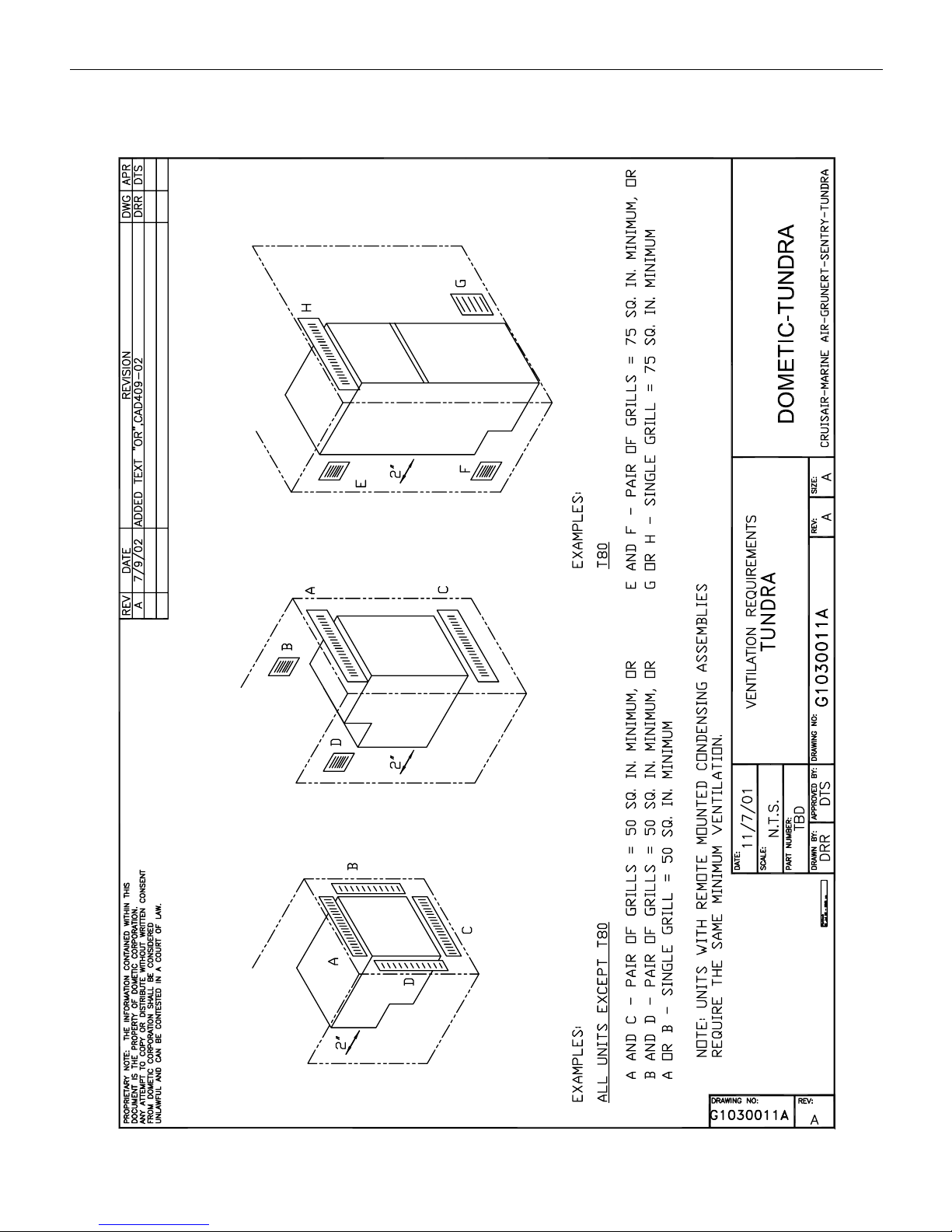
Tundra Ventilation Requirements
Installation
4
inches for air entry and discharge.) A lower entry, and
upper discharge is preferred. See Ventilation Requirements
diagram in this manual.
Install appliance away from heat sources in a dry and wellventilated area. Avoid direct contact with water. The
appliances are
not waterproof.
Overload Protections
The compressor overload and start protection cuts off
power to the compressor if the compressor speed drops
below approximately 1,900 rpm, or if this motor speed is
not reached during the start sequence. Possible reasons for
overload protection activating could be too high refrigeration system pressures during operation or lack of pressure
equalizing at start.
Electrical Connection
Before connecting the appliance to the power supply, check
that the line voltage corresponds to the indications on the
appliance rating plate and those of the compressor plate.
This appliance complies with EC directive 89/336 governing
radio suppression.
DC Wiring
For Direct Current (DC) refrigerators, connect the appliance
to the DC distribution center. A circuit breaker of 15 Amps
(maximum) must be used if the system is 12VDC, and 10
Amps (maximum) if the system is 24VDC. Make sure that
proper polarity is maintained at all times. Check that all
grounding systems are in good working order. The appli-
ance must be wired and grounded in accordance with
the Electrical Wiring Guidelines in this manual.
DANFOSS Compressor Data
Voltage Range
12V systems: From 10.4V to 17V
24V systems: From 22.8V to 31.5V
The electronic unit will calibrate automatically to the applied
voltage. This means that if the battery voltage is less than
17V, the electronic unit assumes that it is working in a 12V
system. If the voltage is higher than 17V, the electronic unit
assumes that it is working in a 24V system. However, the
compressor does not run at power supply voltages between
about 17V and 22.8V, the desired battery protection cut-out
voltage for 24V systems.
Protection Systems
The Danfoss compressor protection system facilitates
protection against compressor overload and start failure,
fan overload and electronic unit overheating as well as
destructive battery discharge. When an overload protection
is activated, the compressor enters a cycle in which it
makes start attempts at approximately 60 second intervals
until a successful start is achieved.
The fan overload protection stops the compressor if the fan
current exceeds 0.5 A
An overheating of the electronic unit heat sink will cause
the compressor to stop. Restart will occur automatically
when a normal temperature has been reached. If a fan is
installed, it will continue to run when the compressor stops
due to overload or electronic unit overheating.
(avg)
or 1 A
(peak)
.
Voltage Protection
If a voltage outside any concerned range is applied to the
electronic unit, the compressor does not start, or it stops if
the voltage limit is exceeded during operation. The compressor will restart automatically approximately 1 minute
after the supply voltage has reached the reset voltage
within the range in question.
Battery Protection
The Danfoss electronic unit provides protection as follows:
Standard Battery Protection Settings
12V cut-out 12V cut-in 24V cut-out 24V cut-in
10.4 11.7 22.8 24.2
Final Installation Notes
• For all appliances, AVOID the use of any electrical
adapters or extension cords.
• After installation, allow the appliance to sit for at least
one hour before starting.
• The manufacturer assumes no responsibility for any
injuries or damage caused by noncompliance with
any of the installation regulations.
Installation
5
 Loading...