

Dometic TRIM LINE 9472 010 Series, TRIM LINE 9472 016 Series, TRIM LINE 9472 5 Series, TRIM LINE 9479 010 Series, TRIM LINE 9472 013 Series Installation Instructions Manual
Page 1
USA
SERVICE OFFICE
Dometic Corporation
1120 North Main Street
Elkhart, IN 46514
RECORD THIS UNIT INFORMATION FOR
FUTURE REFERENCE:
Model Number ____________________
Serial Number ____________________
Date Purchased ____________________
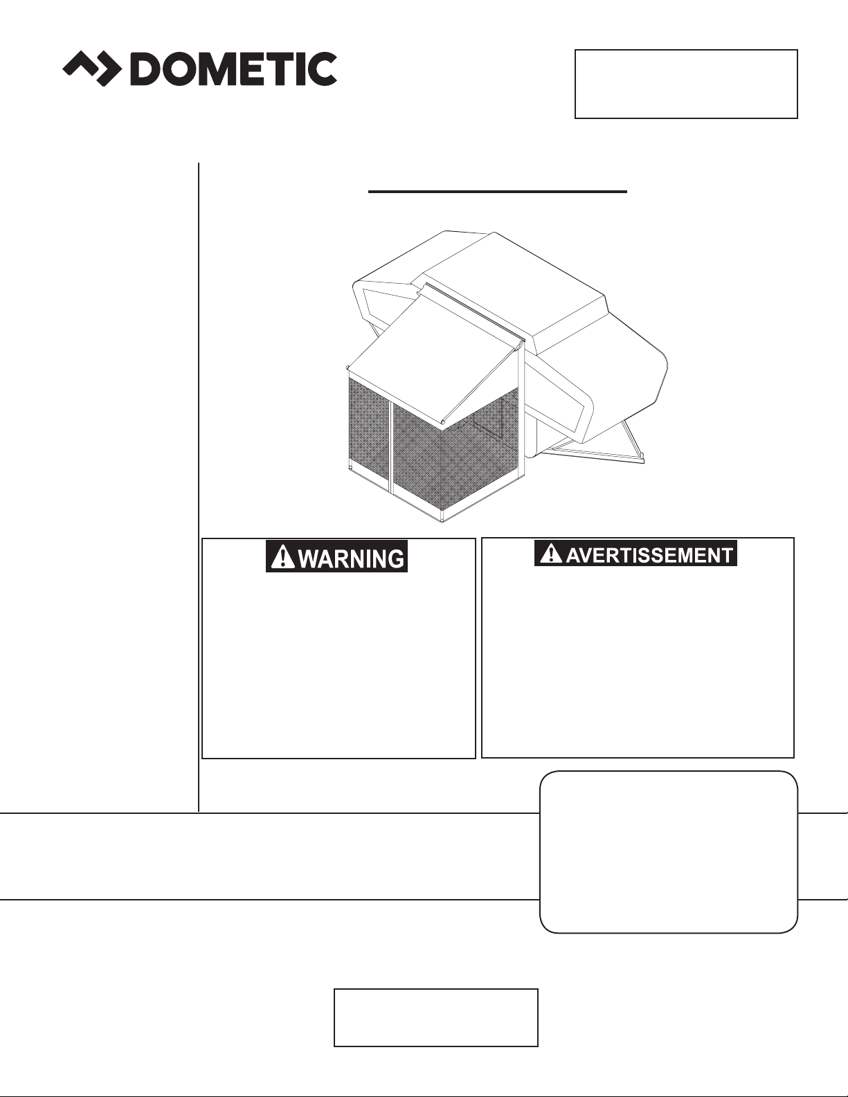
TRIM LINE
RV SCREEN ROOM
CANADA
Dometic Corporation
46 Zatonski, Unit 3
Brantford, ON N3T 5L8
CANADA
SERVICE CENTER &
DEALER LOCATIONS
Please Visit:
www.eDometic.com
INSTALLATION
INSTRUCTIONS
This manual must be read and
understood before installation,
adjustment, service, or maintenance is performed. This unit must
be installed by a qualied service
technician. Modification of this
product can be extremely hazardous and could result in personal
injury or property damage.
Lire et comprendre ce manuel avant
de procéder à l'installation, à des réglages, de l'entretien ou des réparations. L'installation de cet appareil doit
être effectuée par un réparateur quali-
é. Toute modication de cet appareil
peut être extrêmement dangereuse et
entraîner des blessures ou dommages
matériels.
Models
9472XX.010
9472XX.013
9472XX.016
9472XX.5XX
9479XX.010
REVISION A
Form No. 3307958.045 09/16
(French 3307959.043_A)
©2016 Dometic Corporation
LaGrange, IN 46761 U.S.A.
Important: These Instructions
must stay with unit.
Owner read carefully.
Page 2
SAFETY INSTRUCTIONS
This manual has safety information and instructions to help users eliminate or reduce the risk
of accidents and injuries.
RECOGNIZE SAFETY INFORMATION
This is the safety-alert symbol. When you see this
symbol in this manual, be alert to the potential
for personal injury.
Follow recommended precautions and safe operating instructions.
UNDERSTAND SIGNAL WORDS
A signal word , WARNING OR CAUTION is used
with the safety-alert symbol. They give the level
of risk for potential injury.
TRIM LINE SCREEN ROOM
INSTALLATION
APPLICATION:
The A&E Trim Line Screen Room is available in sizes to
correspond with the various sizes of Trim Line Awnings.
TOOLS REQUIRED FOR INSTALLATION:
Pencil 1/8 Drill Bit
Measuring Tape Center Punch
Phillips Screwdriver Hammer/Mallet
Drill (for Hook Stakes)
IMPORTANT: Read the entire installation procedure
before starting the installation.
Dometic Corporation reserves the right to modify appear-
ances and specications without notice.
INSTALLATION
During installation, care must be taken not to scrape and
damage the panel and skirt.
1. In order to correctly match the Screen Room to
the right size Trim Line Awning, you must know the
length of the awning. See FIG. 1A.
The A&E Trim Line Screen Room consists of (1)
continuous panel for the front/sides, a rear skirt and
wheel cover. See FIG. 1B.
indicates a potentially hazard-
ous situation which, if not avoided, could result
in death or serious injury.
indicates a potentially hazard-
ous situation which, if not avoided, may result in
minor or moderate injury.
used without the safety alert
symbol indicates, a potentially hazardous situation which, if not avoided, may result in property
damage.
Read and follow all safety information and instructions.
FIG. 1A
SELECTING THE
CORRECT SIZE
LENGTH
(AWNING SIZE)
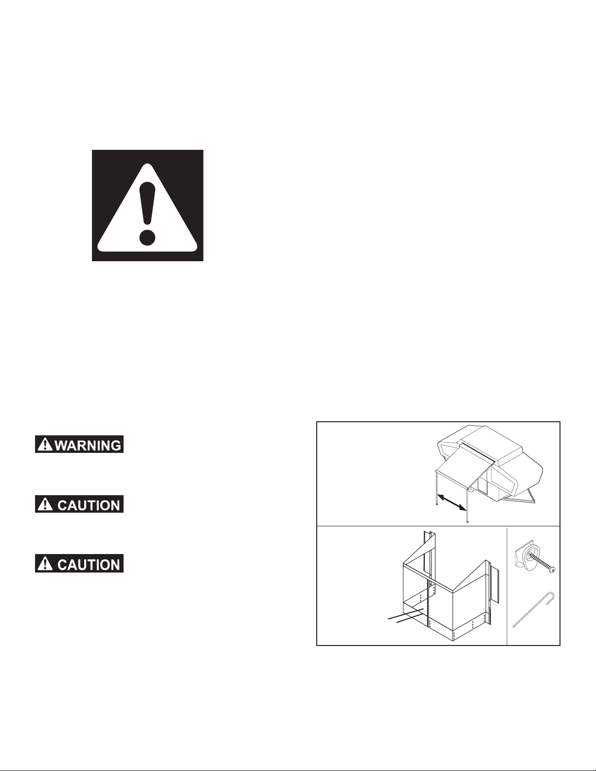
FIG. 1B
SNAP
FASTENER &
SCREW
STAKE
FRONT & SIDE
PANELS ARE ONE PIECE
FIG. 1C
The above-mentioned panel and skirt are secured to
the vehicle, the awning and to the ground by means
of zippers, snap fasteners, PE clips, and hook
stakes (provided). See FIG. 1C.
Page 3

Note: The inner and outer sides of all panels can be
checked by looking at the snap fasteners. The round
black plastic ring in the vertical edge hems is on the inside surface.
2. Set up awning for installation of Trim Line Screen
Room.
3. To facilitate accurate installation, vehicle should be
parked on reasonably at ground.
Open awning and install front support and side rafter
pole as shown in FIG. 2
FIG. 2
AWNING FABRIC
SIDE VIEW
SIDE RAFTER POLE
6. Be sure the aps are folded out from the screen
room. Starting at the roof, align top snap fasteners
on each side ap to wall of camper. Locate positions of snap fasteners and mark with pencil. Drill
1/8” holes and install snap fastener with protruding
section pointing toward the screen room. Repeat on
other side. See FIG. 5. (See also specic instructions in Constellation Supplement to Campers
Owner’s Manual.)
7. Align skirt at the right hand ap of screen room and
frame of camper. Attach PE clips sewn on skirt onto
frame ledge on underside of camper. See FIG. 4.
FRONT
SUPPORT
SIDE OF
VEHICLE
4. After awning is set up, remove screen room from
carton, check for correct size and position it with
awning as shown in FIG. 3.
FIG. 3
Zippers sewn on side
and under valance
Align skirt with right hand ap
of screen room
Attach PE clips or
hook strips to frame
Attach skirt to screen room
with hook & loop
fasteners.
FIG. 4
8. Secure bottom of panels by driving the hook stakes
into the ground through the appropriate grommet.
Wrap screen room aps around roof jacks. (See
FIG. 5)
9. Attach skirt to Screen Room with hook and loop
fasteners sewn into room and skirt. See FIG. 4.
FIG. 5
Snap fastener (3 or 4)
on each side ap.
Wrap aps around
roof jacks
5. Fasten front of screen room to Trim Line bag awning
by joining zippers. Start at awning front and fasten
side panels to bottom side of awning. When attaching screen room to awning at bag, pull bag down
and away from awning, making sure screen room is
fastened completely.
Tie straps attach
around support pole
Grommets (7)
sets per unit
Snap fasteners
to point towards
screen room.
Page 4

WHEEL COVER
MOUNTING INSTRUCTIONS
1. Place the wheel cover in position to cover the wheel
opening and mark the locations of the snap fasteners. See FIG. 6.
STORING TRIM LINE SCREEN ROOM
A convenient storage bag is provided to store the Screen
Room.
Screen Room should be dry before storing.
Note: The .570 model wheel well skirt is supplied at a
longer length to cover a dual-axle wheel cover. Customers w/single –axle trailers will need to fold skirt in half so
that 3 snap fasteners are visible and then cut away the
excess panel.
2. With a 1/8” drill bit, pilot drill a shallow hole at each
marked location and install a snap fastener (provided in plastic bag) with the protruding section facing
down toward the ground See FIG. 6.
3. Install the wheel cover by eyelet on the wheel cover
under the protruding part of the snap fastener, and
then push the eyelet up and onto the snap fastener
to connect. See FIG. 6.
FIG. 6
IMPORTANT- SNAP STUD
OPERATION
To attach screen room side panel or wheel well cover
to side of camper, insert the protruding thumb-like portion of the snap stud, on the side of the camper, into
the black plastic ring of the snap fastener crimped into
the hems. Push or snap, the other side of the fastener
over the back side of the stud.
To detach Screen Room Side Panel or Wheel Well
Cover from the side of the trailer, pull on the hem edge
lifting the grommet off of the non-protruding side of
the snap stud. Do not force or pull from the protruding
side of the stud, as this may cause grommets attached
to the fabric to become separated from the fabric or
may damage the snap fastener.
Do not operate appliances venting into this
room enclosure with privacy panels closed.
At least one panel must be open for ventilation when using appliances. Death or serious injury from Carbon Monoxide Poisoning
could occur if not operated properly.
4. Take the 3 inch pieces of hook and loop strip; remove peel strip and stick them onto the screen room
skirting opposite the hook and loop strips on the
wheel cover. See FIG. 6.
 Loading...