

Dometic Travel Power 3.5, Travel Power 5.0, Travel Power 5.0 ASC, Travel Power 8.0 Operating Manual
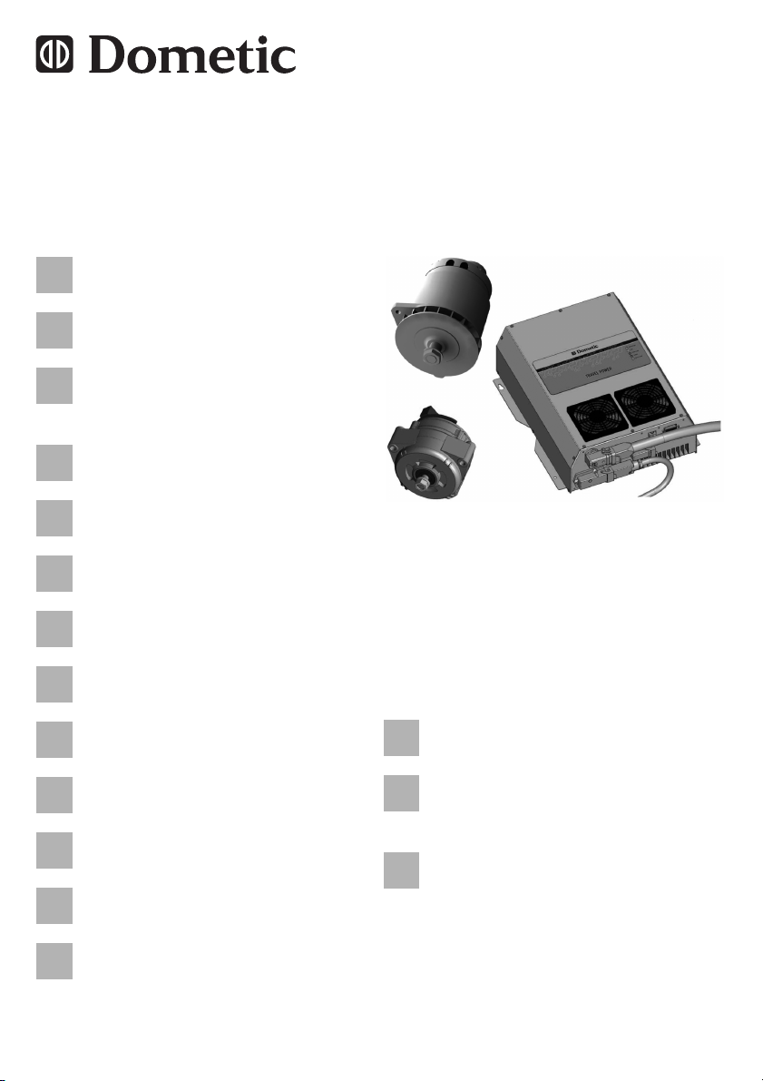
Generator with power box
EN
DE
FRESIT
NLDASVNOFI
PTRUPL
CS
SK
HU
Operating Manual . . . . . . . . . . . . . . 12
Generator mit Elektrobox
Bedienungsanleitung. . . . . . . . . . . . 30
Générateur avec boîte
d'alimentation
Notice d’utilisation . . . . . . . . . . . . . . 49
Generador con caja eléctrica
Instrucciones de uso . . . . . . . . . . . . 70
Generatore con Power Box
Istruzioni per l’uso . . . . . . . . . . . . . . 90
Generator met elektrobox
Gebruiksaanwijzing . . . . . . . . . . . . 111
Travel Power
3.5,
Generator med elektroboks
Betjeningsvejledning . . . . . . . . . . . 131
Generator med elbox
Bruksanvisning . . . . . . . . . . . . . . . 150
Generator med styreskap
Bruksanvisning . . . . . . . . . . . . . . . 169
Generaattori ja sähkörasia
Käyttöohje . . . . . . . . . . . . . . . . . . . 187
Gerador com caixa elétrica
Manual de instruções. . . . . . . . . . . 206
Генератор с электрощитом
Инструкция по эксплуатации. . . . 226
Generator ze skrzynką
elektryczną
Instrukcja obsługi. . . . . . . . . . . . . . 247
5.0, 5.0 ASC,
8.0
Generátor s elektroboxem
Návod k obsluze . . . . . . . . . . . . . . 266
Generátor s elektrickým
rozvádzačom
Návod na obsluhu. . . . . . . . . . . . . 285
Generátor elektromos
dobozzal
Használati utasítás . . . . . . . . . . . . 304

Dometic Travel Power
1
2
1
2
1
5 kW
3.5 kW
8 kW
1
2
3
4
2
3
Dometic Travel Power
1
2
3
4
5
3
4
4
5
4
3
2
1
+
-
LL
2
7
1
3
5
6
8
9
10
11
12
13
4
5
Dometic Travel Power
5
Dometic Travel Power
0
200
400
600
800
1000
1200
1400
1600
1800
2000
2200
2400
2600
2800
3000
3200
3400
3600
RPM
WATT
2000 2500 3000 3500 4000 4500 5000 5500 6000 6500 7000
TravelPower 3.5
6
0
400
800
1200
1600
2000
2400
2800
3200
3600
4000
4400
4800
5200
RPM
WATT
2000 2500 3000 3500 4000 4500 5000 5500 6000 6500 7000 7500 8000 8500 9000
TravelPower 5.0
TravelPower 5.0 ASC
TravelPower 5.0/5.0 ASC
7
6
Dometic Travel Power
5200
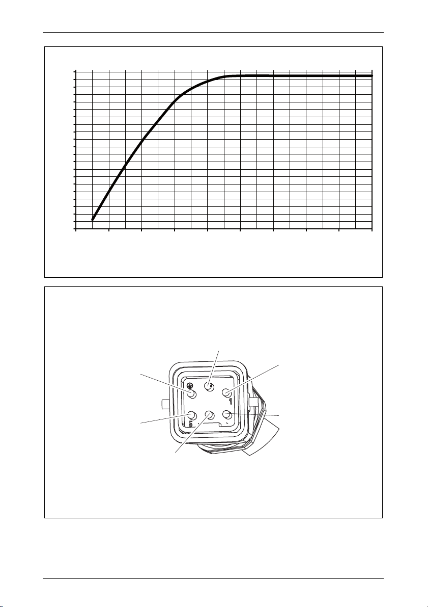
TravelPower 8.0
0
400
800
1200
1600
2000
2400
2800
3200
3600
4000
4400
4800
5200
6000
6400
6800
7200
7600
8000
8400
2500 3000 3500 4000 4500 5000 5500 6000 6500 7000
5600
RPM
WATT
8
9
3
1
2
5
4
GND
7
Dometic Travel Power
5
4
3
2
1
4
5
1
2
3
0
a
b
8
280
123
299
314
402,5
56 271
9
376
c
Dometic Travel Power
9
1 2
d
Dometic Travel Power
10
Dometic Travel Power
PRODUCT No.
Serial No.
958 500 035
84600203
1
2
e
PRODUCT No.
Serial No.
958 500 070
8XXXXXXXXXX
1
2
f
11

EN
Dometic Travel Power
Please read this instruction manual carefully before first use, and store
it in a safe place. If you pass on the product to another person, hand
over this instruction manual along with it.
Table of contents
1 Explanation of symbols . . . . . . . . . . . . . . . . . . . . . . . . . . . . . . . . . . 13
2 General safety instructions . . . . . . . . . . . . . . . . . . . . . . . . . . . . . . . 14
3 Target group . . . . . . . . . . . . . . . . . . . . . . . . . . . . . . . . . . . . . . . . . . 15
4 Scope of delivery . . . . . . . . . . . . . . . . . . . . . . . . . . . . . . . . . . . . . . . 16
5 Accessories . . . . . . . . . . . . . . . . . . . . . . . . . . . . . . . . . . . . . . . . . . . 16
6 Spare parts . . . . . . . . . . . . . . . . . . . . . . . . . . . . . . . . . . . . . . . . . . . 17
7 Intended use . . . . . . . . . . . . . . . . . . . . . . . . . . . . . . . . . . . . . . . . . . 17
8 Technical description . . . . . . . . . . . . . . . . . . . . . . . . . . . . . . . . . . . . 18
9 Checking before use . . . . . . . . . . . . . . . . . . . . . . . . . . . . . . . . . . . . 20
10 Using Travel Power . . . . . . . . . . . . . . . . . . . . . . . . . . . . . . . . . . . . . 21
11 Troubleshooting . . . . . . . . . . . . . . . . . . . . . . . . . . . . . . . . . . . . . . . . 22
12 Maintenance . . . . . . . . . . . . . . . . . . . . . . . . . . . . . . . . . . . . . . . . . . 26
13 Guarantee . . . . . . . . . . . . . . . . . . . . . . . . . . . . . . . . . . . . . . . . . . . . 27
14 Disposal . . . . . . . . . . . . . . . . . . . . . . . . . . . . . . . . . . . . . . . . . . . . . . 27
15 Technical data . . . . . . . . . . . . . . . . . . . . . . . . . . . . . . . . . . . . . . . . . 28
12

EN
Dometic Travel Power Explanation of symbols
1 Explanation of symbols
WARNING!
!
A
I
➤ Action: This symbol indicates that action is required on your part. The
required action is described step-by-step.
✓ This symbol describes the result of an action.
BA10: This information refers to another manual included in the scope of
delivery where you can find more details, in this case on the BA10.
Fig. 1 5, page 3: This refers to an element in an illustration. In this case,
item 5 in figure 1 on page 3.
Safety instruction: Failure to observe this instruction can cause
fatal or serious injury.
NOTICE!
Failure to observe this instruction can cause material damage and
impair the function of the product.
NOTE
Supplementary information for operating the product.
13

EN
General safety instructions Dometic Travel Power
2 General safety instructions
The manufacturer accepts no liability for damage in the following cases:
Faulty assembly or connection
Damage to the product resulting from mechanical influences and excess
voltage
Alterations to the product without express permission from the manu-
facturer
Use for purposes other than those described in the operating manual
Please observe the following basic safety information when using electrical
devices to protect against:
Electric shock
Fire hazards
Injury
2.1 General safety
WARNING!
!
People (including children) whose physical, sensory or mental
capacities or whose lack of experience or knowledge prevent
them from using this product safely should not use it without the
supervision or instruction of a responsible person.
Electronic devices are not toys
Keep electrical appliances out of reach of children or infirm persons. Do not let them use the appliances without supervision.
Use the Travel Power only as intended.
A qualified electrician must do the 230 V AC installations
( Installation manual).
14

EN
Dometic Travel Power Target group
2.2 Operating the device safely
WARNING!
!
The output voltage of the Travel Power generator is considera-
bly higher than the output voltage of a regular vehicle generator.
No extra connections must be made to the Travel Power
generator under any circumstances.
The Travel Power generator with power box must never come
into contact with the regular 230-Vw network or the12/24-Vg-
system of the vehicle. If external power from the regular 230 V
network is wanted a two phase, three positioned selector or similar must be installed between the Travel Power lines and the
regular lines ( Installation manual).
The power box cover is not to be removed at any time. Service
on the Travel Power must only be made by an authorised workshop.
Only appliances marked 220 V or 230 V may be connected to
Travel Power.
Extension cables for work outside the vehicle must be suitable
for outdoor use:
– 16 A: cable diameter 2.5 mm²; length maximum 100 m
– 25/36 A: cable diameter 4 mm²; length maximum 100 m
If the on/off switch is in the on-position when the vehicle engine
starts the Travel Power will immediately generate 230 V to the
outlet. Ensure that appliances not intended for use are switched
off or disconnected.
3 Target group
This operating manual is for the user of the generator.
15

EN
Scope of delivery Dometic Travel Power
4 Scope of delivery
No. in
fig. 1,
page 3
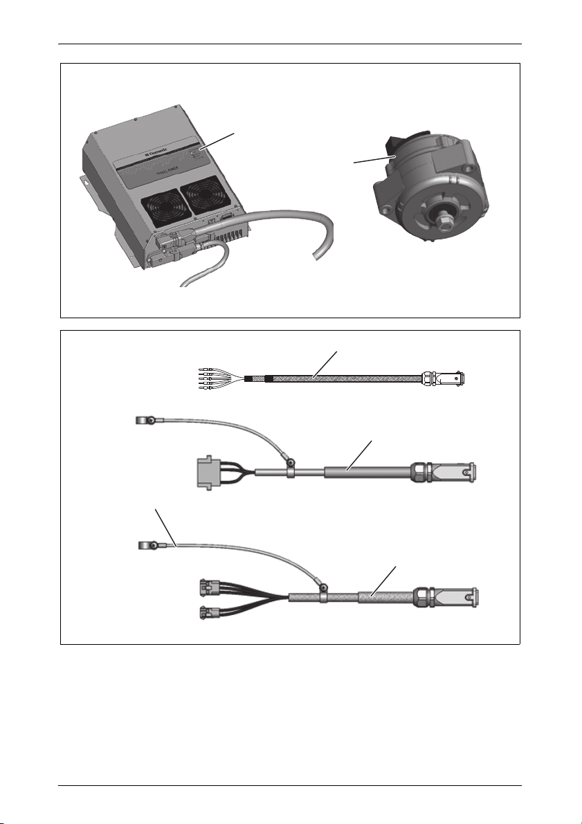
1 Power box
2 Generator
– Installation Manual
– Operating Manual
A
Description
Can be used with this power box only!
NOTICE!
For the proper use of the Travel Power only use original parts
from Dometic as listed above. These three parts shall be installed
and handled according to the instructions in this manual.
5 Accessories
Available as accessory (not included in scope of delivery):
No. in
fig. 1,
page 3
1 – 3 Connection cable between generator and power
1 – 3 Connection cable between generator and power
1 – 3 Connection cable between generator and power
1 – 3 Connection cable between generator and power
– Control panel with 7 m connection cable 9103002009
4 Adapter cables for old Travel Power systems
Description Item number
box, 3 m
box, 5 m
box, 7 m
box, 10 m
Contact customer service if you have any questions
(see back page).
16
9103001000
9103001001
9103001002
9103001003

EN
Dometic Travel Power Spare parts
6 Spare parts
Complete power box (fig. 1, page 3)
Connectors:
– Output connector (fig. 3 , 2, page 4)
– Battery connector (fig. 3 ,3, page 4)
– Panel connector (optional) (fig. 3 , 4, page 4)
Shielded connection cable (fig. 1 3, page 3)
Adapters for old connection cables (fig. 2 4, page 3)
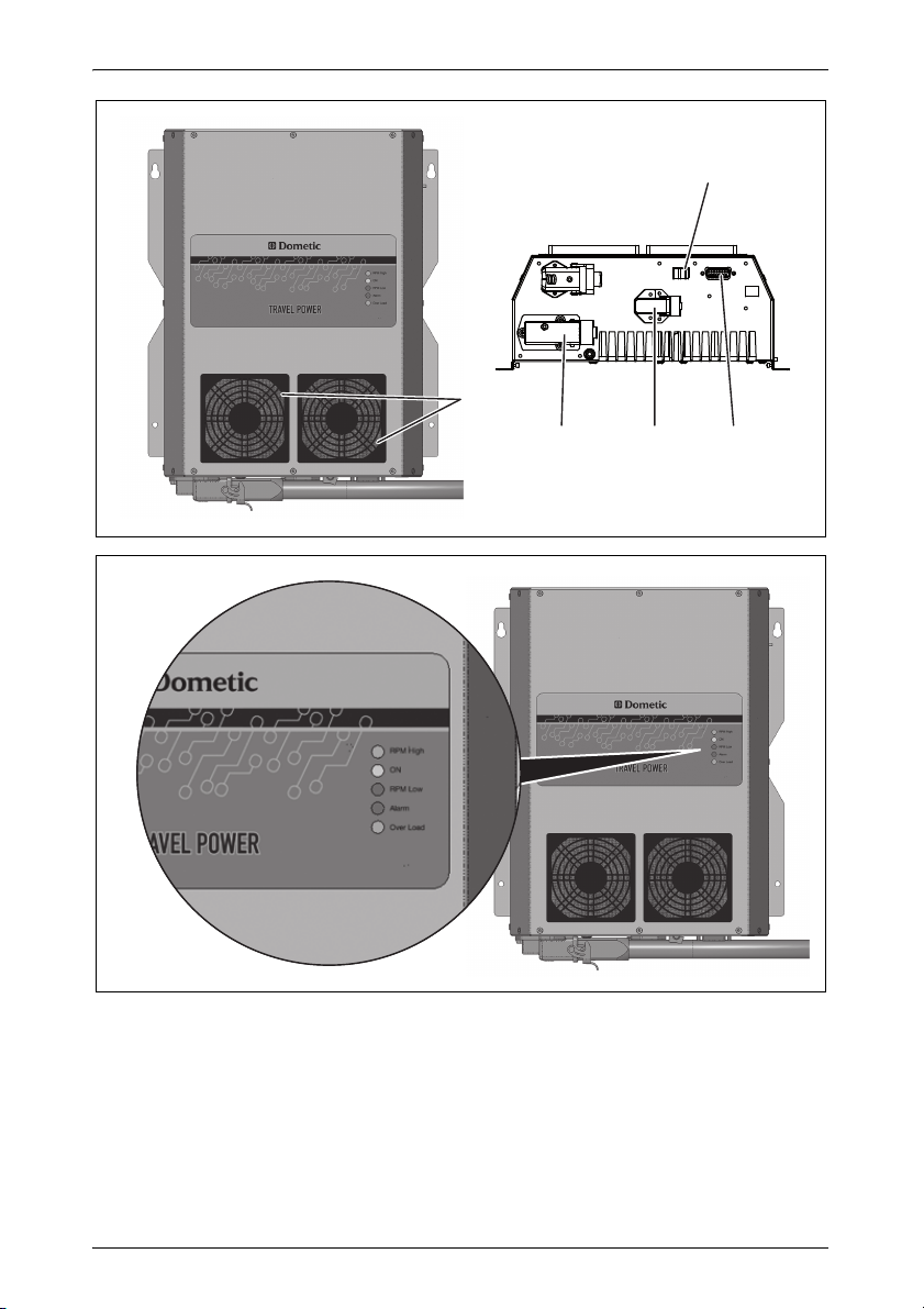
Cover filters (fig. 3 ,1, page 4)
Filters (fig. 3 1, page 4)
Generator
Complete generator (fig. 1 2, page 3)
Complete brush holder set
Set washers for alignment
Warning label for generator
7 Intended use
The Dometic Travel Power transforms mechanical energy, supplied by an
engine, through the Travel Power generator and the power box into a sine
wave voltage of 230 V~/50 Hz and delivers a current up to:
Travel Power 3.5: 16 A (Item no. 9103000000)
Travel Power 5.0: 25 A (Item no. 9103000001)
Travel Power 5.0 ASC: 25 A (Item no. 9102900197)
Travel Power 8.0: 36 A (Item no. 9103000002)
The Dometic Travel Power system is designed for use in vehicles (automobiles and trucks).
17

EN
Technical description Dometic Travel Power
8 Technical description
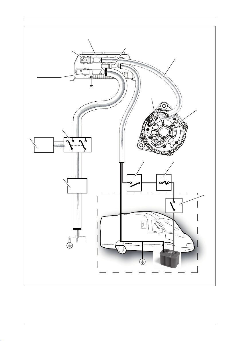
8.1 Function
Key for fig. 5, page 5:
No. Description
1 Power box
2 Battery connector
3 Shielded cable
4 3-pole generator socket
5 2-pole generator socket
6 Optional Switch
7 Fuse 10 A
8 Vehicle key
9 RCCB
10 External power supply
11 Switch of external power supply
12 Output connector
13 Generator connector
The Travel Power generator with power box consists of the following three
main parts:
power box
generator
shielded cable (between the generator and the power box with different
lengths)
The generator is fixed with special brackets on an vehicle engine. It supplies
the requested electrical energy through the shielded cable to the power box.
The power box transforms the incoming current from the generator to a
usable sine wave current at a constant frequency of 50 Hz ± 0.5 % and a
stable voltage of 230 V ± 7 % (RMS).
Additionally, the power box protects itself and the connected electrical consumer if any critical conditions occur such as low speed, overload.
18

EN
Dometic Travel Power Technical description
The electrical box indicates operating modes and errors (e.g. low or high
speeds, overload) on the LEDs.
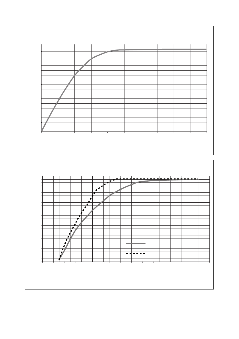
Travel Power delivers a sine wave voltage of 230 Vw/50 Hz. The frequency
is not dependent on the engine speed however the power loading is.
Depending on the vehicle engine speed, Travel Power delivers constantly a
current up to
Travel Power 3.5: 16 A
Travel Power 5.0: 25 A
Travel Power 8.0: 36 A
Travel Power functions by means of a battery:
Travel Power 3.5 – 5.0: 12 V battery (cars) and 24 V battery (trucks)
Travel Power 5.0 ASC: only 12 V battery (cars)
Travel Power 8.0 W: only 24 V battery (trucks)
8.2 Displays and control elements
Displays see fig. 4, page 4
LED Colour Description
RPM High yellow Engine speed too high for the needed electrical power
ON green Flashing: ready (no engine speed)
Constantly lit: 230 V available
RPM Low red Engine speed to Iow for the needed electrical power
Alarm red Slowly flashing: Temperature protection active
Constantly lit: High/low voltage protection active
Constantly lit: Short circuit
Overload yellow Protection limit of current exceeded
Control elements see fig. 3, page 4
No. in
fig. 3, page 4
5 On/Off-switch
Description
19

EN
Checking before use Dometic Travel Power
9 Checking before use
WARNING!
!
9.1 Mechanical control
➤ Check the generator and make sure that it is securely and irremovable
mounted on the engine.
➤ Check the pulleys and make sure that they are parallel and aligned.
➤ Make sure that the belt and the pulleys can run without obstruction.
➤ Make sure that the belt is tightened according to the manufacture’s
instructions.
➤ Make sure that the belt has sufficient clearance in order not to damage
surrounding parts at large load changes.
➤ Check that the power box is mounted correctly:
– on a plane surface
– in a well-ventilated area
– protected against moisture
Check the mechanical and electrical installation of the generator
and power thoroughly before turning on the ignition and using
Travel Power.
➤ Check that the openings of the power box are not covered.
9.2 Electrical control
➤ Make sure that all the wiring is done in a secure and correct way.
➤ Make sure that all cables are undamaged, unloaded, securely attached,
not rubbed or pinched in any way.
➤ Check that all cables are mounted and tightened in a proper way.
➤ Check that all connectors and socket screws are well tightened.
➤ Check that all appliances not intended for use are turned off or discon-
nected.
➤ Make sure that the earth connection is correctly installed.
20

EN
Dometic Travel Power Using Travel Power
10 Using Travel Power
10.1 Precautions before starting Travel Power
➤ Before switching on the power box please check:
– that appliances not intended for use are turned off or disconnected
– that the engine is correctly running
(if not: the green LED is flashing)
– that the requested/needed electrical power is adequate for the nominal
Travel Power output
(if not: the power box starts with auto-protection, the red LED is
continuously lit)
– that the alternator’s revolutions are adequate for the requested
electrical power
(if not: the power box starts with auto-protection, the red LED is
continuously lit)
10.2 Starting Travel Power
➤ Switch on the power box (fig. 3 5, page 4).
➤ Check the LEDs of the power Box (see chapter “Displays and control ele-
ments” on page 19).
➤ When the green LED is continuously lit switch on the electrical load
according to the nominal load and the correspondent alternator’s speed.
See the following graphics:
– 3.5 kW: fig. 6, page 6
– 5 kW and 5 kW ASC: fig. 7, page 6
– 8kW: fig. 8, page 7
If the green LED is not continuously lit see chapter “Troubleshooting” on
page 22.
10.3 Shutting down Travel Power
➤ Turn off all appliances which shall not restart automatically when Travel
Power will be switched on again.
➤ Switch off the power box (fig. 3 5, page 4).
21

EN
Troubleshooting Dometic Travel Power
11 Troubleshooting
11.1 Description of remote control LEDs
LED
Name Brief description
AC Over
Volt age
AC Under
Voltage
DC Over
Voltage
No RPM Engine stopped RPM lower than limit
Overspeed Alarm engine RPM
Low RPM Engine RPM too low
High RPM Engine RPM too high
Shutdown Output short circuit Numbers of impulses from PWM
Overload Alarm overload Maximum (18.5 A) and of I2t
Overtemperature
MagFault Short circuit in
Vdriver Low Alarm excitation
Param Error Parameters module
Isolation Fail Caused by HW Yes Yes Yes C
Limit
Overload
passed
Output voltage too
high
Output voltage too low Voltage lower than limit (180 V)
Voltage DC Bus too
high
out of limit
for required energy
for required energy
Alarm high temperature
excitation
voltage too low or
M165 fault
M165 fault
Description activation and end
of activation
Voltage higher than limit (260 V)
for a certain time (1.3 s)
for a certain time (3.6 s)
Alarm produced by HW Yes Yes Yes C
(1.200 min-1)
RPM higher than limit Delay for
RPM lower than limit No No No C C
RPM higher than limit No No No C C
with CC detected
(1400 W/s)
Limit (60 °C) exceeded
The alarm resets when the tem-
perature descents under the limit
Alarm caused by HW Yes Yes Yes C
Voltage of inner circuit less than
limit (14.4 V)
Control parameters Yes Yes Yes C
Interruption
excitation
Yes Ye s Ye s C
Yes Ye s Ye s C
No – No F
download
bus
Yes Ye s Ye s C
Yes Ye s Ye s C
Yes D el ay
Yes Ye s Ye s C
No No No
Inter-
Critical
ruption
Alarm?
RPM HighOnRPM Low
Yes Ye s C
Yes F
for fan
supply
Alarm
Overload
C Continuously lit
F Slowly flashing
22
EN
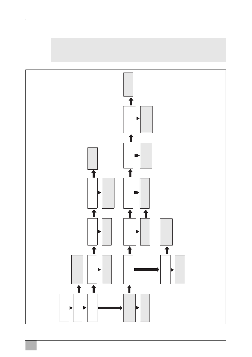
Dometic Travel Power Troubleshooting
Power at the
230V-outlet?
No
Refer to “Fault
tracing when Power
Box stops working“
No
Is the green
LED2 lit?
Is the RCCB ok?
device ok?
Are the 230 V wiring
and contacs ok?
Check connected
equipment
Replace or
repair
Fix 230 V wiring
or contacts
Is the remote
control in ON-
position?
Are the 3 A fuses
ok?
Is the generator
speed
sufficient?
Is the battery
voltage ok?
Is the belt trans-
mission ok?
Are the cables ok?
Voltage at both
ends?
Contact
service
Turn on the
remote control
Increase the
speed
Check battery
Check the belt
transmission
Check for
broken cables
or contacts
Is the cause clear?
Remove the cause
and change the
fuses
No
Contact service
No
No No
No
No
No
No
No
Is the red
LED lit?
Yes
Yes
Is the switching
Contact
service
Yes
Yes
Yes
Yes
Yes Yes
Yes
Yes
Yes Ye s
No
No
Yes
11.2 Fault tracing
WARNING! Danger of electrocution!
!
Be careful when fault tracing the Travel Power. Be aware that the
system is a 230 V installation.
23
EN
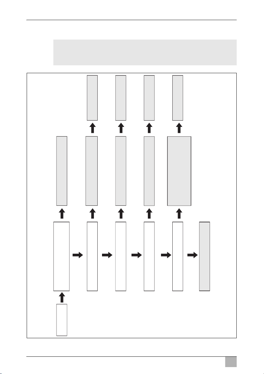
Troubleshooting Dometic Travel Power
Is the red
LED4 lit?
Yes
Have severel connections and
disconnections of large loads
within a short interval occurred?
Restart and avoid such behavior
Has a large motor or compressor load
been connected?
Does the battery have over or
under voltage?
Has the temperature
protection been triggered?
Reduce the load and avoid starting large
motors/compressors at the same time
Is there a slackness in the 230 V
installation or in the generator wiring?
Check the wiring
Take care of the battery according to
the manufacturer's recommandations
Yes
No
No
Restart TravelPower
with the remote control
No
No
No
Yes
Restart TravelPower
with the remote control
Restart TravelPower
with the remote control
Restart TravelPower
with the remote control
Yes
Yes
Yes
Check that the power box installation
is ok. Make sure the ventilation
openings are unobstructed.
Make sure the ambient temperature
is normal.
LED4
slowly
flashing
Contact sevice
11.3 Fault tracing when the power box stops working
WARNING! Danger of electrocution!
!
Be careful when fault tracing the Travel Power. Be aware that the
system is a 230 V installation.
24

EN
Dometic Travel Power Troubleshooting
11.4 Fault tracing before contacting the retailer
WARNING!
!
Before contacting the Travel Power representative the following items
should be checked:
1. Check if all connectors are well connected and if all socket screws are
well tightened (fig. 5, page 5).
I
2. If item 1 is found correct, loosen the generator connector from the power
box.
Measure the resistance between all the outlets in the generator connector on PIN3–4–5 (fig.8, page 7).
The resistance between two of the outlets pins should be
– 3.5 kW: 5.3 Ω±0.25 Ω
– 5 kW: 2.9 Ω±0.25 Ω
– 8 kW: 783 mΩ±20 mΩ
The resistance between the outlets of PIN 1 and 2 should be
– 3.5 kW: 2.85 Ω±0.1 Ω
– 5 kW: 2.85 Ω±0.1 Ω
– 8 kW: 7,35 Ω±0,30 Ω
3. If a short-circuit (0 Ω) or an infinite resistance is measured in any of the
measurements during item 2 check that the connection of the shielded
cable to the generator is properly done.
If the connection is proper disconnect the shielding cable from the
generator.
The resistance between socket connections 1 – 2, 2 – 3 and 3 – 1
should be
– 3.5 kW: 5.3 Ω±0.25 Ω
– 5 kW: 2.9 Ω±0.25 Ω
– 8 kW: 783 mΩ±20 mΩ
In order to avoid any risk from electrical current or voltage assure
that the Travel Power is switched off and the engine was stopped
before starting the fault tracing.
NOTE
A voltage drop at smaller loads can be caused by bad connections of the shielded cable connectors.
25

EN
Maintenance Dometic Travel Power
The resistance between socket connection 4 – 5 should be
– 3.5 kW: 2.85 Ω±0.1 Ω
– 5 kW: 2.85 Ω±0.1 Ω
– 8kW: 7,35 Ω±0,30 Ω
Measure the resistance between the generator housing and each of the
cables 1 through 5 (fig. 0, page 8). The resistance should be more than
1MΩ for a sufficient insulation between winding and ground.
If any resistance value is incorrect the generator must be exchanged.
However, if all measurements are correct check carefully the shielded
cable, because a short-circuit or a break in the cable is likely.
Measure at both ends the resistance of each cable part to recognise any
short-circuit.
Twist and turn the cable to see any possible damages.
12 Maintenance
NOTE
I
The following influences shorten the generator’s lifetime:
wrong installation
constant high speed of the generator
dirt and filth on the generator
For maintenance observe the following instructions:
➤ Check if the power box’ filters are in good condition or if they have to be
replaced.
➤ Check if the generator’s brushes are in good condition or have to be
replaced.
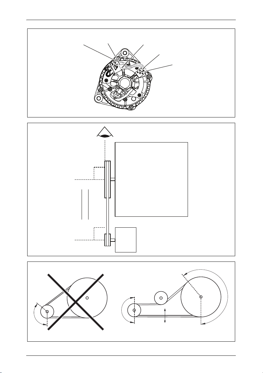
➤ Check the belt alignment.
NOTICE!
A
The generator pulley must be mounted in parallel and aligned to
the crankshaft pulley as shown in fig. a, page 8.
If the pulley installation is not made correctly problems due to belt
wear are likely to occur.
26

EN
Dometic Travel Power Guarantee
➤ Check the belt and pulley condition.
To ensure good performance, the area of contact between belt and
pulley should be as large as possible.
To ensure sufficient clearance for the belt and to maintain a large contact
area idlers and/or tensions may be stretched as shown in fig. b, page 8.
➤ Check if all screws are well tightened.
If necessary, tighten the screws with the correct moment.
➤ If necessary, clean the electrical connections.
13 Guarantee
The statutory warranty period applies. If the product is defective, please
contact your retailer or the manufacturer's branch in your country (see the
back of the instruction manual for the addresses).
For repair and guarantee processing, please include the following documents when you send in the device:
A copy of the receipt with purchasing date
A reason for the claim or description of the fault
14 Disposal
➤ Place the packaging material in the appropriate recycling waste bins
wherever possible.
If you wish to finally dispose of the product, ask your local recycling
centre or specialist dealer for details about how to do this in
M
accordance with the applicable disposal regulations.
27

EN
Technical data Dometic Travel Power
15 Technical data
15.1 Power box
Travel Power
3.5 5.0 5.0 ASC 8.0
Battery: 12/24 V 12 V 24 V
Output voltage: 230 V~ ± 7 % (RMS)
Output power continuously (resistive load):
Phase: 1
Wave form: Sinus ≤ 3% sprain
Frequency: 50 Hz ± 0.5 %
Max. constant current: 16 A
Max. start current for
320 ms:
Efficiency: 95 %
Automatic protection: – Short circuit
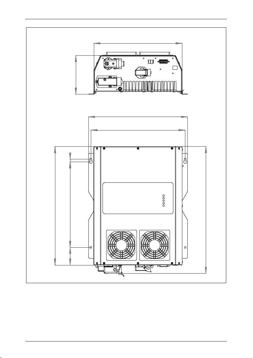
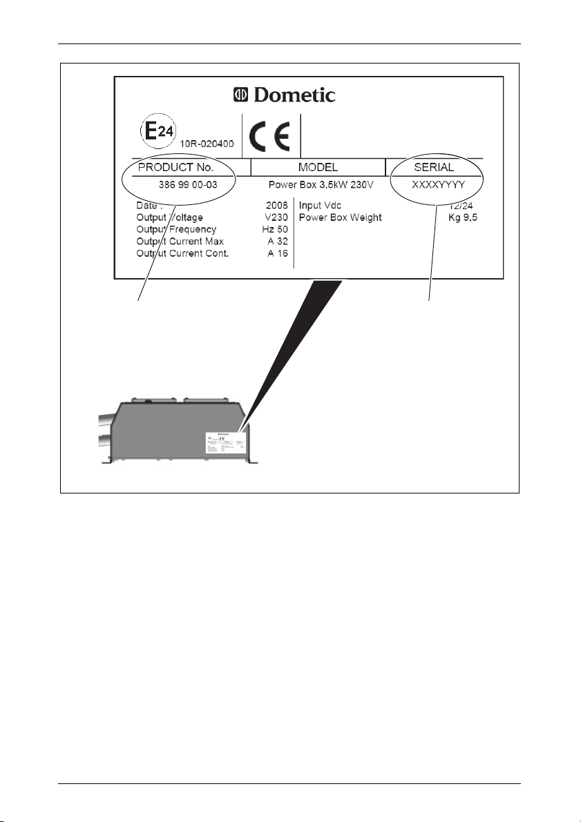
Type plate: see fig. d, page 10
Dimensions
(W x D x H):
Hole distance: 280 x 299 mm
Weight: 9.3 kg 9.5 kg 9.2 kg
Certifications:
3.5 kW ±
5%
(± 5% RMS)
32 A
(Peak value)
5 kW ± 5% 8kW ± 5%
25 A
(± 5% RMS)
40 A
(Peak value)
– overload
– over temperature
– low/high RPM
– low/high voltage
314 x 125 x 380 mm
see fig. c, page 9
36 A
(± 5% RMS)
85 A (Peak value)
24
10R-020400 10R-020412 10R-030568 10R-030487
28

EN
Dometic Travel Power Technical data
15.2 Generator
Travel Power
3.5 5.0 / 5.0 ASC 8.0
Max. rotor voltage: 14,4 Vg 27 Vg ± 0,1 V
Rotor resistance: 2.85 Ω ± 0,1Ω 7,35 Ω ± 0,30 Ω
Stator phases: 3
Max. stator voltage: 340 V (RMS)
Stator resistance
(between phases): 5.3 Ω ± 0.25 Ω 2.9 Ω ± 0.25 Ω 783 Ω ± 0,20 Ω
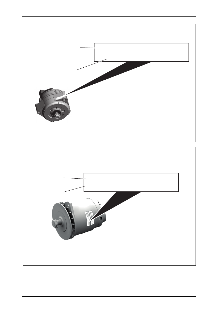
Type plate: see fig. e, page 11 see fig. f,
page 11
No. 1 = product number of the generator
No. 2 = serial number of the generator
Dimensions (W x D x H): 159 x 178 x 190 mm 260 x 200 x
300 mm
Weight: 7.1 kg 15.5 kg
29

DE
Dometic Travel Power
Bitte lesen Sie diese Anleitung vor der Inbetriebnahme sorgfältig durch
und bewahren Sie sie auf. Geben Sie sie im Falle einer Weitergabe des
Produktes an den Nutzer weiter.
Inhaltsverzeichnis
1 Erklärung der Symbole . . . . . . . . . . . . . . . . . . . . . . . . . . . . . . . . . . 31
2 Grundlegende Sicherheitshinweise . . . . . . . . . . . . . . . . . . . . . . . . . 32
3 Zielgruppe dieser Anleitung . . . . . . . . . . . . . . . . . . . . . . . . . . . . . . . 33
4 Lieferumfang . . . . . . . . . . . . . . . . . . . . . . . . . . . . . . . . . . . . . . . . . . 34
5 Zubehör . . . . . . . . . . . . . . . . . . . . . . . . . . . . . . . . . . . . . . . . . . . . . . 34
6 Ersatzteile . . . . . . . . . . . . . . . . . . . . . . . . . . . . . . . . . . . . . . . . . . . . 35
7 Bestimmungsgemäßer Gebrauch . . . . . . . . . . . . . . . . . . . . . . . . . . 35
8 Technische Beschreibung . . . . . . . . . . . . . . . . . . . . . . . . . . . . . . . . 36
9 Vor der Inbetriebnahme prüfen . . . . . . . . . . . . . . . . . . . . . . . . . . . . 38
10 Travel Power verwenden . . . . . . . . . . . . . . . . . . . . . . . . . . . . . . . . . 39
11 Fehler suchen . . . . . . . . . . . . . . . . . . . . . . . . . . . . . . . . . . . . . . . . . 41
12 Wartung . . . . . . . . . . . . . . . . . . . . . . . . . . . . . . . . . . . . . . . . . . . . . . 45
13 Garantie . . . . . . . . . . . . . . . . . . . . . . . . . . . . . . . . . . . . . . . . . . . . . . 46
14 Entsorgung. . . . . . . . . . . . . . . . . . . . . . . . . . . . . . . . . . . . . . . . . . . . 46
15 Technische Daten . . . . . . . . . . . . . . . . . . . . . . . . . . . . . . . . . . . . . . 47
30
 Loading...