

Page 1
REFRIGERATION
EN
DE
8 SERIES
RM8xxx, RMS8xxx, RML8xxx,
RMSL8xxx
Absorber refrigerator
Installation Manual
Absorber-Kühlschrank
Montageanleitung
Page 2

Page 3
English
Installation instructions
Absorption refrigerator for recreation vehicles
RM 8400 RM 8401 RM 8405 RM 8500 RM 8501 RM 8505 RM 8550 RM 8551 RM 8555
RMS 8400 RMS 8401 RMS 8405 RMS 8460 RMS 8461 RMS 8465 RMS 8500 RMS 8501
RMS 8505 RMS 8550 RMS 8551 RMS 8555 RML 8550 RML 8551 RML 8555 RMSL 8500
RMSL 8501 RMSL 8505
N 1-1
MBA 05/2012
EN
Page 4

Table of contents
0.0 Unpacking and Transport . . . . . . . . . . . . . . . . . . . . . . . . . . . . . . . . 3
1.0 General . . . . . . . . . . . . . . . . . . . . . . . . . . . . . . . . . . . . . . . . . . . . . . 4
1.1 Introduction . . . . . . . . . . . . . . . . . . . . . . . . . . . . . . . . . . . . . . . . . . . . . . . . . . . . . . . . . . . . . . . . 4
1.2 Guide to these operating instructions . . . . . . . . . . . . . . . . . . . . . . . . . . . . . . . . . . . . . . . . . . . .4
1.3 Copyright protection . . . . . . . . . . . . . . . . . . . . . . . . . . . . . . . . . . . . . . . . . . . . . . . . . . . . . . . . . 4
1.4 Explanation of symbols used in this manual . . . . . . . . . . . . . . . . . . . . . . . . . . . . . . . . . . . . . . . 4
1.5 Warranty . . . . . . . . . . . . . . . . . . . . . . . . . . . . . . . . . . . . . . . . . . . . . . . . . . . . . . . . . . . . . . . . . . . 5
1.6 Limitation of liability . . . . . . . . . . . . . . . . . . . . . . . . . . . . . . . . . . . . . . . . . . . . . . . . . . . . . . . . . . 5
1.7 Declaration of conformity . . . . . . . . . . . . . . . . . . . . . . . . . . . . . . . . . . . . . . . . . . . . . . . . . . . . . . 5
2.0 Safety instructions . . . . . . . . . . . . . . . . . . . . . . . . . . . . . . . . . . . . . . 6
2.1 Application according to regulations . . . . . . . . . . . . . . . . . . . . . . . . . . . . . . . . . . . . . . . . . . . . .6
2.2 User's responsibility . . . . . . . . . . . . . . . . . . . . . . . . . . . . . . . . . . . . . . . . . . . . . . . . . . . . . . . . . . 6
2.3 Working upon and checking the refrigerator . . . . . . . . . . . . . . . . . . . . . . . . . . . . . . . . . . . . . . . 6
2.4 Operating the refrigerator with gas . . . . . . . . . . . . . . . . . . . . . . . . . . . . . . . . . . . . . . . . . . . . . . 6
3.0 Description of model . . . . . . . . . . . . . . . . . . . . . . . . . . . . . . . . . . . . 7
3.1 Model identification . . . . . . . . . . . . . . . . . . . . . . . . . . . . . . . . . . . . . . . . . . . . . . . . . . . . . . . . . . 7
3.2 Refrigerator rating plate . . . . . . . . . . . . . . . . . . . . . . . . . . . . . . . . . . . . . . . . . . . . . . . . . . . . . . . 7
3.3 Technical data . . . . . . . . . . . . . . . . . . . . . . . . . . . . . . . . . . . . . . . . . . . . . . . . . . . . . . . . . . . . . . 7
4.0 Installation instructions . . . . . . . . . . . . . . . . . . . . . . . . . . . . . . . . . . 10
4.1 Installation . . . . . . . . . . . . . . . . . . . . . . . . . . . . . . . . . . . . . . . . . . . . . . . . . . . . . . . . . . . . . . . . . 10
4.1.1 Side installation . . . . . . . . . . . . . . . . . . . . . . . . . . . . . . . . . . . . . . . . . . . . . . . . . . . . . . . . . . . . . . . . . . . . . . 10
4.1.2 Side installation with floor-roof ventilation . . . . . . . . . . . . . . . . . . . . . . . . . . . . . . . . . . . . . . . . . . . . . . . . . 11
4.1.3 Rear installation . . . . . . . . . . . . . . . . . . . . . . . . . . . . . . . . . . . . . . . . . . . . . . . . . . . . . . . . . . . . . . . . . . . . . 11
4.1.4 Draught-proof installation . . . . . . . . . . . . . . . . . . . . . . . . . . . . . . . . . . . . . . . . . . . . . . . . . . . . . . . . . . . . . . 12
4.2 Ventilation and air extraction of the refrigerator . . . . . . . . . . . . . . . . . . . . . . . . . . . . . . . . . . . . 13
4.3 Installing the ventilation system . . . . . . . . . . . . . . . . . . . . . . . . . . . . . . . . . . . . . . . . . . . . . . . . . 14
4.4 Exhaust gas duct and installing the fume flue . . . . . . . . . . . . . . . . . . . . . . . . . . . . . . . . . . . . . . 15
4.5 Installation recess . . . . . . . . . . . . . . . . . . . . . . . . . . . . . . . . . . . . . . . . . . . . . . . . . . . . . . . . . . . . 16
4.5.1 Installation in the recess . . . . . . . . . . . . . . . . . . . . . . . . . . . . . . . . . . . . . . . . . . . . . . . . . . . . . . . . . . . . . . . 16
4.6 Securing the refrigerator . . . . . . . . . . . . . . . . . . . . . . . . . . . . . . . . . . . . . . . . . . . . . . . . . . . . . . 17
4.7 Inserting of the decor panel . . . . . . . . . . . . . . . . . . . . . . . . . . . . . . . . . . . . . . . . . . . . . . . . . . . . 17
4.8 Gas installation . . . . . . . . . . . . . . . . . . . . . . . . . . . . . . . . . . . . . . . . . . . . . . . . . . . . . . . . . . . . . . 19
4.9 Electrical installation . . . . . . . . . . . . . . . . . . . . . . . . . . . . . . . . . . . . . . . . . . . . . . . . . . . . . . . . . . 20
4.9.1 Mains connection . . . . . . . . . . . . . . . . . . . . . . . . . . . . . . . . . . . . . . . . . . . . . . . . . . . . . . . . . . . . . . . . . . . . 20
4.9.2 Battery connection . . . . . . . . . . . . . . . . . . . . . . . . . . . . . . . . . . . . . . . . . . . . . . . . . . . . . . . . . . . . . . . . . . . 20
4.9.3 Terminal strip . . . . . . . . . . . . . . . . . . . . . . . . . . . . . . . . . . . . . . . . . . . . . . . . . . . . . . . . . . . . . . . . . . . . . . . 21
4.9.4 D+ and solar connection (only for AES models) . . . . . . . . . . . . . . . . . . . . . . . . . . . . . . . . . . . . . . . . . . . . 21
4.9.5 Wiring diagrams . . . . . . . . . . . . . . . . . . . . . . . . . . . . . . . . . . . . . . . . . . . . . . . . . . . . . . . . . . . . . . . . . . . . . 22
Dometic GmbH
In der Steinwiese 16
D-57074 Siegen
www.dometic.com
© Dometic GmbH - 2011 - Subject to change without notice
2
Page 5
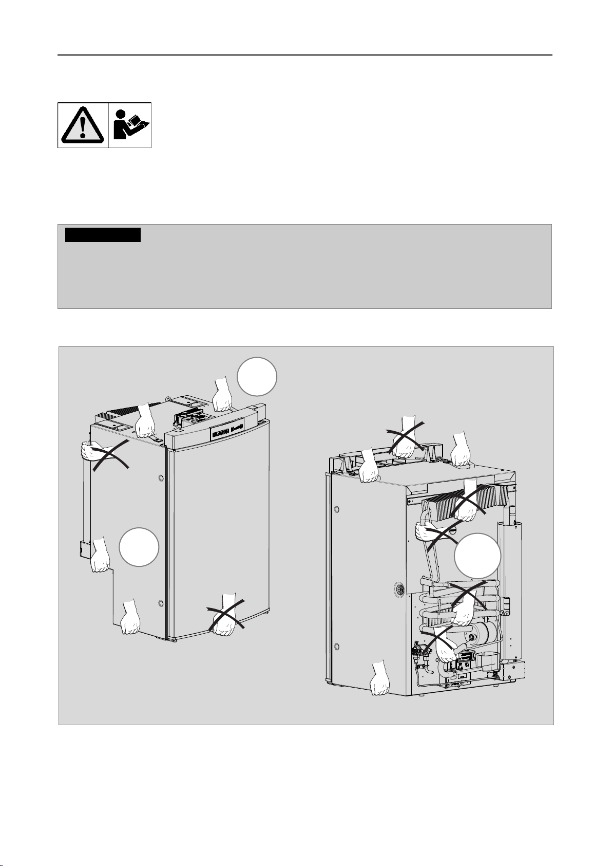
0.0 Unpacking and Transport
Lifting / carrying the refrigerator
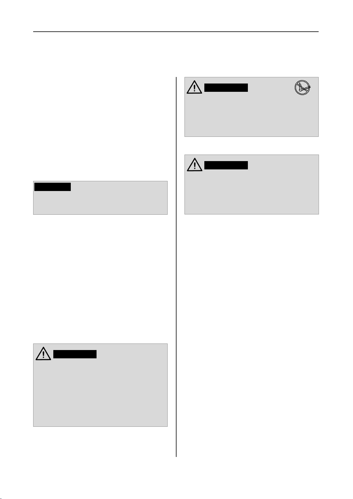
CAUTION!
Never use parts on the refrigerator other than those shown in the illustration (particularly
not the cooling unit, gas lines and control panel) for carrying or lifting the refrigerator !
This prevents damage to the refrigerator.
OK
OK
NOT
OK
3
Page 6
General
1.0 General
1.1 Introduction
On installation of the appliance, the technical
and administrative regulations of the country
in which the vehicle will first be used must be
adhered to. Otherwise the refrigerator must be
installed as described in these instructions. In
Europe, for example, gas appliances, cable
routing, installation of gas cylinders, as well as
approval and checking for leaks must comply
with EN 1949 for liquid gas systems in vehi-
cles.
1.2 Guide to these installation
instructions
Before you start installing the refrigerator,
please read the installation instructions
carefully.
These instructions provide you with the necessary guidance for the proper installation of
your refrigerator. Observe in particular the
safety instructions. Observation of the
instructions and handling recommendations is
important for dealing with the refrigerator
safely and for protecting you from injury and
the refrigerator from damage. You must understand what you have read before you carry out
a task.
Keep these instructions in a safe place
close to the refrigerator so they may be
referred to at any time.
1.4 Explanation of symbols
used in this manual
Warning notices
Warning notices are identified by symbols. A
supplementary text gives you an explanation
of the degree of danger.
Observe these warning notices rigorously.
You will thus protect yourself and other
people from injury, and the appliance from
damage.
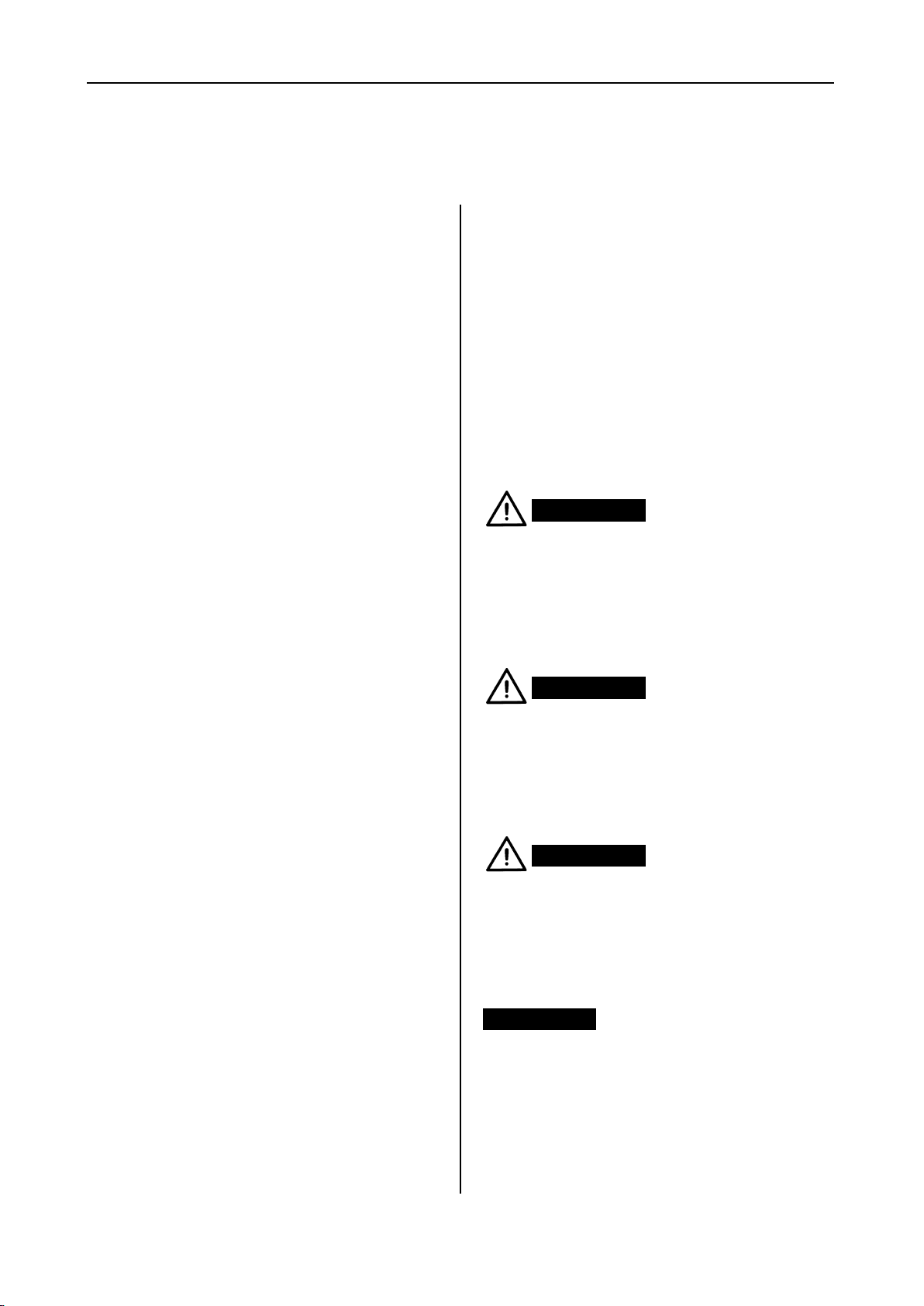
DANGER!
DANGER indicates an imminent hazardous
situation which, if not avoided, could result in
death or serious injury.
WARNING!
WARNING indicates a potentially hazardous
situation which, if not avoided, could result in
death or serious injury
CAUTION!
WARNING indicates a potentially hazardous
situation which, if not avoided, could result in
death or serious injury
1.3 Copyright protection
The information, texts and illustrations in these
instructions are copyright protected and are
subject to industrial property rights.
No part of these instructions may be reproduced, copied or utilised in any other way without written authorisation by Dometic GmbH,
Siegen.
CAUTION!
CAUTION (used without the safety alert sym-
bol) indicates a potentially hazardous situation
which, if not avoided, may result in damage to
the appliance.
4
Page 7
General
Information
INFORMATION gives you supplementary and
useful guidance when dealing with your refrigerator.
Environmental Tips
ENVIRONMENTAL TIPS gives you useful gui-
dance for saving energy and disposal of the
appliance.
1.6 Limitation of liability
All information and guidance in these operating instructions were prepared after taking
into consideration the applicable standards
and regulations as well as the current state of
the art. Dometic reserves the right to make
changes at any time which are deemed to be
in the interest of improving the product and
safety.
Dometic will assume no liability for damage in
the case of :
non-observation of the operating instructi-
ons
application not in accordance with the
regulations or provisions
use of non-original spare parts
modifications and interferences to the
appliance
effect of environmental influences, such as
- temperature fluctuations
- humidity
1.5 Warranty
Warranty arrangements are in accordance
with EC Directive 44/1999/CE and the normal
conditions applicable for the country concerned. For warranty or other maintenance, please contact our customer services department.
Any damage due to improper use is not covered by the warranty. The warranty does not
cover any modifications to the appliance or
the use of non-original Dometic parts. The
warranty does not apply if the installation and
operating instructions are not adhered to and
no liability shall be entertained.
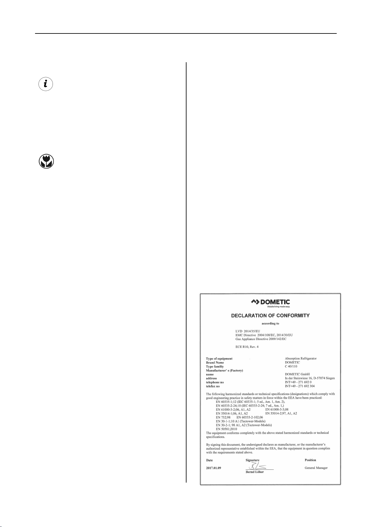
1.7 Declaration of conformity
5
Page 8
Safety instructions
2.0 Safety instructions
2.1 Application according to
regulations
DANGER!
This refrigerator is designed for installation in
recreation vehicles such as caravans or
motorhomes. The appliance has been typeapproval tested for this application in accordance with the EC Gas Directive.
The refrigerator is to be used solely for storing
foodstuffs.
CAUTION!
The refrigerator must not be exposed to
rain.
2.2 User's responsibility
Anyone operating the refrigerator must be
familiar with the safe handling and understand
the advice in these operating instructions.
2.3 Working upon and checking
the refrigerator
Never use an unshielded flame to check
gas bearing parts and pipes for leakage!
There is a danger of fire or explosion.
WARNING!
Never open the absorber cooling unit! It is
under high pressure.
There is a danger of injury!
2.4 Operating the refrigerator
with gas
It is imperative that the operating pressure
corresponds to the data specified on the
rating plate of the appliance. Compare the
operating pressure of the rating plate with the
data specified on the pressure reducing valve
of the liquid gas cylinder.
WARNING!
Work on gas equipment, exhaust system
and electrical facilities must be carried
out by authorised personnel only.
Substantial damage to property and/or
injury to persons can arise through unprofessional procedures.
6
Page 9
3.0 Description of model
Description of model
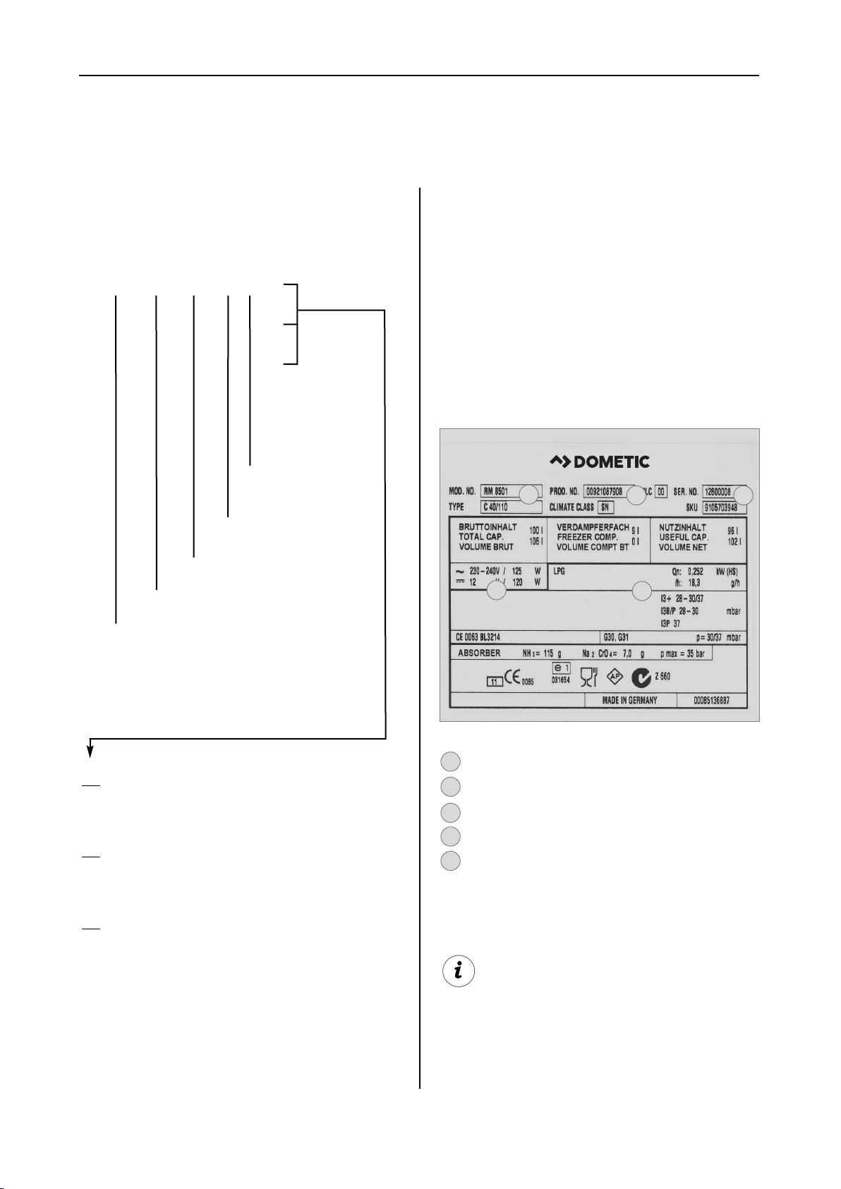
3.1 Model identification
Example :
RM
(S)
(L)
8 4 0 0
1
5
Depth:
0 = Standard
5 = + 55mm
6 = + 65mm
4 = Width 486mm
5 = Width 523mm
Model range
„Large“
Stepped cabinet
3.2 Refrigerator rating plate
The rating plate is to be found on the inside of
the refrigerator. It contains all important details
of the refrigerator. You can read off from this
the model identification, the product number
and the serial number. You will need these
details whenever you contact the customer
service centre or when ordering spare parts.
1
4
2
5
3
Refrigerator Mobile /
Mobile Absorption Refrigerator
0
manual energy selection + manual ignition
(battery igniter)
1
manual energy selection, automatic ignition
(MES)
5
automatic and manual energy selection,
automatic ignition (AES)
Example
Model number
1
Product number
2
Serial number
3
Electrical rating details
4
Gas pressure
5
Dometic refrigerators are equipped for a connection pressure of 30 mbar. For connection
to a 50 mbar gas system, use Truma VDR
50/30 medium pressure controller.
Fig. 1
7
Page 10
Description of model
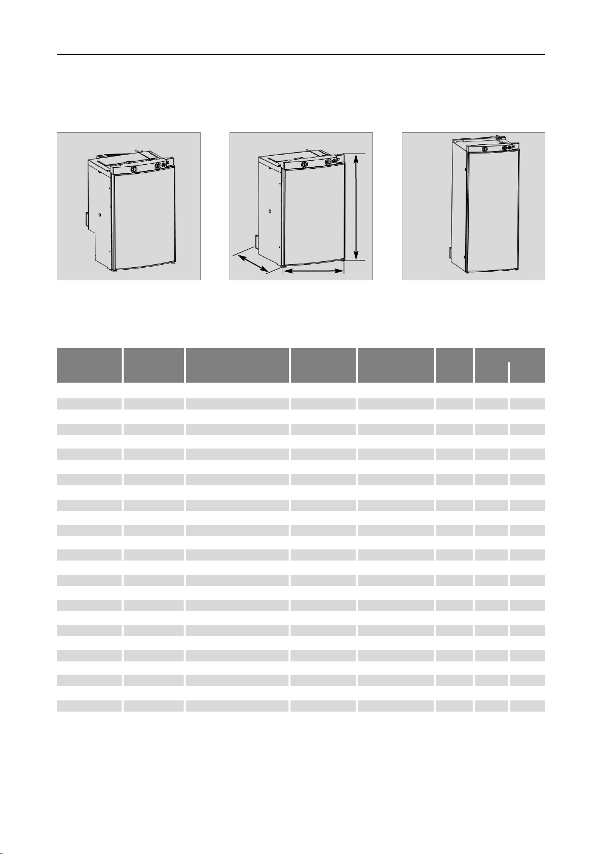
3.3 Technical data
RMS 8xxx
Curved door models
Model Dimensions Gross capacity
RMS 8400
RMS 8401
RMS 8405
RM 8400
RM 8401
RM 8405
RMS 8460
RMS 8461
RMS 8465
RMS 8500
RMS 8501
RMS 8505
RMS 8550
RMS 8551
RMS 8555
RM 8500
RM 8501
RM 8505
RM 8550
RM 8551
RM 8555
RML 8550
RML 8551
RML 8555
RMSL 8500
RMSL 8501
RMSL 8505
H x W x D (mm) with without mains/battery electricity/gas weight Piezo Automat
Depth incl. door freezer compartment over 24hrs
821x486x568
821x486x568
821x486x568
821x486x568
821x486x568
821x486x568
821x486x633
821x486x633
821x486x633
821x523x568
821x523x568
821x523x568
821x523x623
821x523x623
821x523x623
821x523x568
821x523x568
821x523x568
821x523x623
821x523x623
821x523x623
1245x523x625
1245x523x625
1245x523x625
1245x523x568
1245x523x568
1245x523x568
80 / 8 lit.
80 / 8 lit.
80 / 8 lit.
90 / 8 lit.
90 / 8 lit.
90 / 8 lit.
90 / 11 lit.
90 / 11 lit.
90 / 11 lit.
90 / 9 lit.
90 / 9 lit.
90 / 9 lit.
103 /12 lit.
103 /12 lit.
103 /12 lit.
100 / 9 lit.
100 / 9 lit.
100 / 9 lit.
115 /12 lit.
115 /12 lit.
115 /12 lit.
179 /33 lit.
179 /33 lit.
179 /33 lit.
145 /28 lit.
145 /28 lit.
145 /28 lit.
RM 8xxx
D
85 lit.
85 lit.
85 lit.
95 lit.
95 lit.
95 lit.
96 lit.
96 lit.
96 lit.
96 lit.
96 lit.
96 lit.
110 lit.
110 lit.
110 lit.
106 lit.
106 lit.
106 lit.
122 lit.
122 lit.
122 lit.
189 lit.
189 lit.
189 lit.
155 lit.
155 lit.
155 lit.
W
Rating details
125 W / 120 W
125 W / 120 W
125 W / 120 W
135 W / 130 W
135 W / 130 W
135 W / 130 W
125 W / 120 W
125 W / 120 W
125 W / 120 W
125 W / 120 W
125 W / 120 W
125 W / 120 W
125 W / 120 W
125 W / 120 W
125 W / 120 W
135 W / 130 W
135 W / 130 W
135 W / 130 W
135 W / 130 W
135 W / 130 W
135 W / 130 W
190 W / 170 W
190 W / 170 W
190 W / 170 W
190 W / 170 W
190 W / 170 W
190 W / 170 W
RML 8xxx
H
Fig. 3Fig. 2
Consumption * Net Ignition
ca.2,5 KWh / 270 g
ca.2,5 KWh / 270 g
ca.2,5 KWh / 270 g
ca.2,4 KWh / 270 g
ca.2,4 KWh / 270 g
ca.2,4 KWh / 270 g
ca.2,5 KWh / 270 g
ca.2,5 KWh / 270 g
ca.2,5 KWh / 270 g
ca.2,5 KWh / 270 g
ca.2,5 KWh / 270 g
ca.2,5 KWh / 270 g
ca.2,6 KWh / 270 g
ca.2,6 KWh / 270 g
ca.2,6 KWh / 270 g
ca.2,4 KWh / 270 g
ca.2,4 KWh / 270 g
ca.2,4 KWh / 270 g
ca.2,6 KWh / 270 g
ca.2,6 KWh / 270 g
ca.2,6 KWh / 270 g
ca.3,2 KWh / 380 g
ca.3,2 KWh / 380 g
ca.3,2 KWh / 380 g
ca.3,2 KWh / 380 g
ca.3,2 KWh / 380 g
ca.3,2 KWh / 380 g
25 kg
25 kg
25 kg
27 kg
27 kg
27 kg
26 kg
26 kg
26 kg
26 kg
26 kg
26 kg
27 kg
27 kg
27 kg
28 kg
28 kg
28 kg
30 kg
30 kg
30 kg
45 kg
45 kg
45 kg
40 kg
40 kg
40 kg
Fig. 4
•
•
•
•
•
•
•
•
•
•
•
•
•
•
•
•
•
•
•
•
•
•
•
•
•
•
•
8
Page 11

Flat door models
Description of model
Model Dimensions Gross capacity
RMS 8500
RMS 8501
RMS 8505
RMS 8550
RMS 8551
RMS 8555
RM 8500
RM 8501
RM 8505
RM 8550
RM 8551
RM 8555
H x W x D (mm) with without mains/battery electricity/gas weight Piezo Automat
Depth incl. door freezer compartment over 24hrs
821x523x541
821x523x541
821x523x541
821x523x596
821x523x596
821x523x569
821x523x541
821x523x541
821x523x541
821x523x596
821x523x596
821x523x596
86 / 9 lit.
86 / 9 lit.
86 / 9 lit.
99 /12 lit.
99 /12 lit.
99 /12 lit.
96 / 9 lit.
96 / 9 lit.
96 / 9 lit.
111 /12 lit.
111 /12 lit.
111 /12 lit.
92 lit.
92 lit.
92 lit.
106 lit.
106 lit.
106 lit.
102 lit.
102 lit.
102 lit.
118 lit.
118 lit.
118 lit.
Rating details
125 W / 120 W
125 W / 120 W
125 W / 120 W
125 W / 120 W
125 W / 120 W
125 W / 120 W
135 W / 130 W
135 W / 130 W
135 W / 130 W
135 W / 130 W
135 W / 130 W
135 W / 130 W
Consumption * Net Ignition
ca.2,5 KWh / 270 g
ca.2,5 KWh / 270 g
ca.2,5 KWh / 270 g
ca.2,6 KWh / 270 g
ca.2,6 KWh / 270 g
ca.2,6 KWh / 270 g
ca.2,4 KWh / 270 g
ca.2,4 KWh / 270 g
ca.2,4 KWh / 270 g
ca.2,6 KWh / 270 g
ca.2,6 KWh / 270 g
ca.2,6 KWh / 270 g
26 kg
26 kg
26 kg
27 kg
27 kg
27 kg
28 kg
28 kg
28 kg
30 kg
30 kg
30 kg
•
•
•
•
Subject to technical changes.
*Average consumption measured at an average ambient temperature of 25°C in pursuance of ISO Standard.
•
•
•
•
•
•
•
•
9
Page 12
Installation
4.0 Installation instructions
4.1 Installation
WARNING!
The appliance may be installed by authorised personnel only!
The unit and the exhaust duct system must be
in principle installed so that it is accessible for
maintenance work, can be easily installed and
dismantled and removed from the vehicle without great effort.
Installation and connection of the appliance
must comply with the latest technical regulations, as follows:
The electrical installation must comply
with national and local regulations.
The gas installation must comply with
national and local regulations.
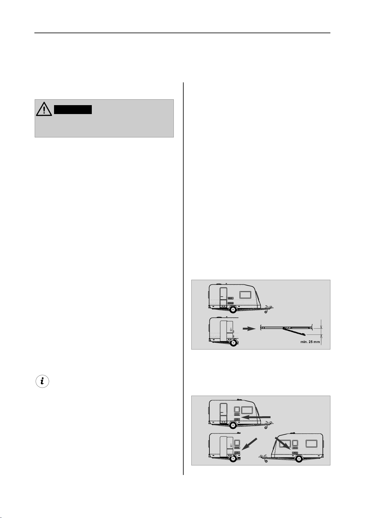
4.1.1 Side installation
If the appliance is installed on the same side of
the vehicle as the entrance door, it is desirable
that the door does not cover the refrigerator's
vents. (Fig. 5, Clearance door/ventilation grille
at least 25 mm). Otherwise ventilation could
be impaired which causes a loss in cooling
performance. Awnings are often placed at the
door side of a caravan. This complicates evacuation of combustion gases and heat through
the ventilation grilles (loss in cooling performance)!
(Fig.5) The air vent grilles are blocked. There
must be a distance between the door and the
air vents of at least 25 mm!
If the door/grille distance is between 25 mm
and 45 mm, we recommend installing a
Dometic ventilation kit (
00/0
) to achieve an optimal cooling perfor-
mance in high ambient temperatures.
item no. 241 2985 -
European Standard EN 1949
European Standards EN 60335-1,
EN 60335-2-24, EN 1648-1 , EN 1648-2
The appliance must be installed in such
a way that it is shielded from excessive
heat radiation.
Excessive heat impairs performance and raises the energy consumption of the refrigerator!
Deviations from these installation instructions without prior notification of Dometic
result in Dometic GmbH's warranty obligations becoming void!
Fig. 5
(Fig. 6) The air vent grilles offer an unobstructed dissipation of heat and exhaust gas even
when the door is opened.
Air vent grille not-
blocked! OK!
10
Fig. 6
Page 13
4.1.2 Side installation with floor-roof
ventilation
Installation
Proper ventilation of the refrigerator can also
be achieved by lower air intake aperture in the
floor and upper roof exhaust vent (see Fig. 7).
A flue has to be provided between the top
edge of the refrigerator and the roof ventilation
which directs the hot air and the exhausts
straight to the air vent in the roof.
The floor opening must have a cross section of
at least 250 cm² . Protect the opening, e.g.
with a baffle plate and a net, to prevent dirt
from entering the gas burner. Compared to
side ventilation, this ventilation method can
allow more dirt to enter the rear area of the
refrigerator, which makes regular maintenance
of the gas burner, at least once a year, necessary.
With this installation method, regular maintenance of the gas burner is only possible
once the device has been dismantled. It is
imperative that the refrigerator be installed
in a way to allow easy removal.
We therefore recommend providing an adequate access opening (service flap) for
ready serviceability from the outside.
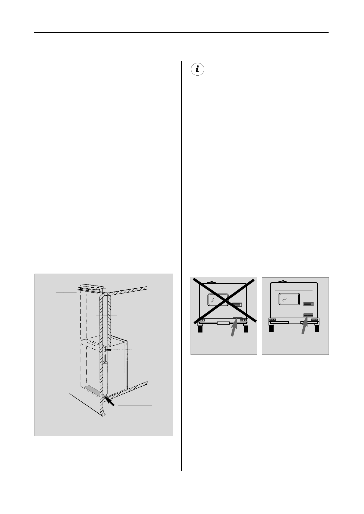
4.1.3 Rear installation
Rear installation often causes an unfavourable
installation arrangement, as ideal ventilation
cannot always be assured (e.g. the lower ventilation grille is covered by the bumper or the
rear lights of the vehicle!) (Fig. 8). The maximum cooling performance of the aggregate is
actually not available.
Recommendation:
Roof vent
R500
hot air
condenser
floor opening:
at least 50 mm wide,
at least 520 mm long
Fig. 7
Air vent grille
blocked !
Fig. 8
Air vent grille not
blocked ! OK!
Fig. 9
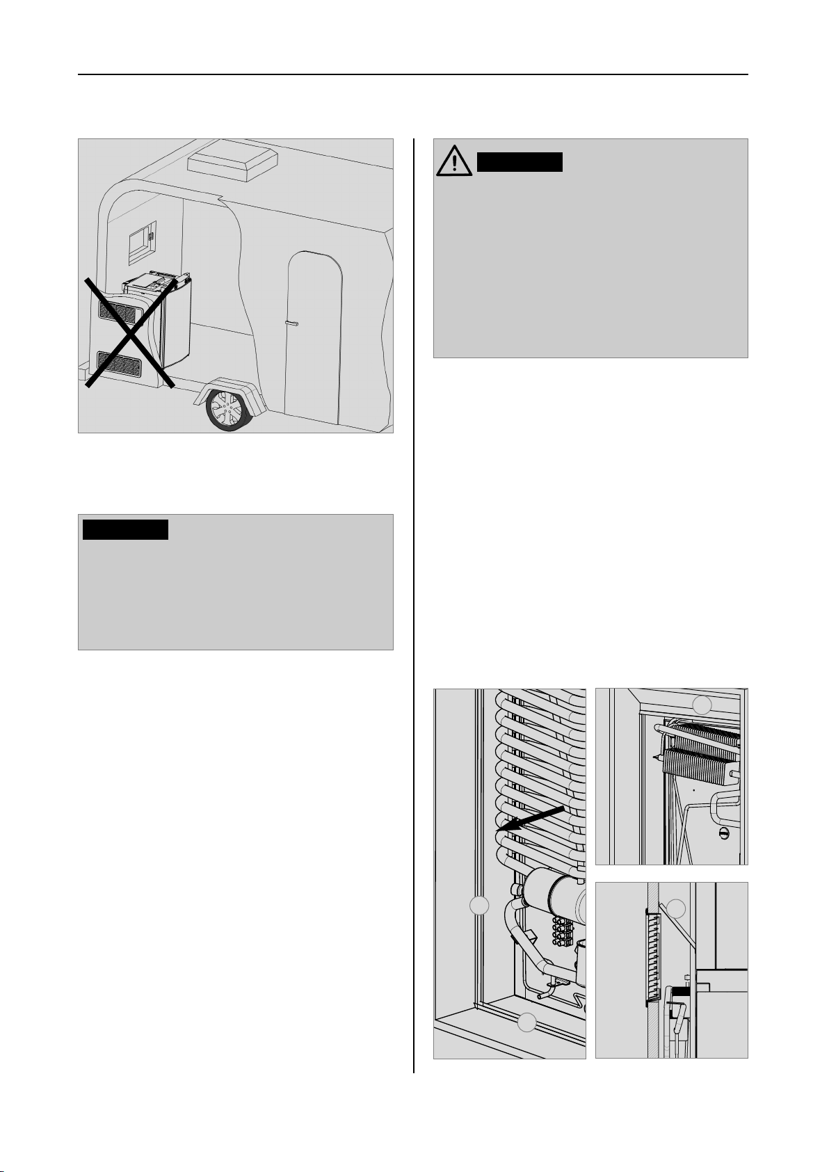
Another unfavourable method of rear installation is to install the air intake and exhaust grilles (Fig. 10) at the side wall of the recreation
vehicle. The air-heat recirculation is very
restricted which means that heat exchangers
(condenser, absorber) cannot be adequately
cooled. The optional method of an additional
air vent grille installed in the floor also exhibits
an insufficient air flow duct.
11
Page 14
Installation
WARNING!
By no means use durable sealing compounds, fitting foam or similar material to
realise draught-proof installation of the
refrigerator! Do NOT use any easily inflammable materials for sealing (in particular
silicon sealing compound or similar). Risk
of fire! The device manufacturer's product
liability and warranty shall lapse if such
materials are used.
Fig. 10
CAUTION!
The maximum cooling performance is not
available! Do not apply this installation
method, as it does not provide proper ventilation! Please refer to the description in
section 4.2 .
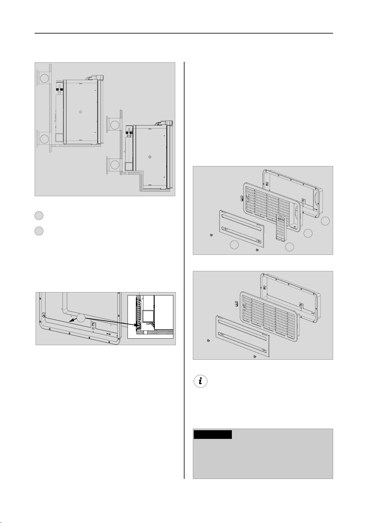
4.1.4 Draught-proof installation
Refrigerators in motorhomes, caravans or
other vehicles must be installed in a draughtproof manner (EN 1949). This means that the
combustion air for the burner is not taken from
the living space and that exhaust fumes are
prevented from entering the living space.
Proposal 1
The lip seals (1) are installed at the bottom and
on each side in the installation recess (Fig. 11-
13). A heat deflector plate (2) is installed in the
installation recess above the refrigerator. Affix
the this plate to the caravan wall, do NOT
attach to the refrigerator !
Attach the deflector plate so that the heated
air escapes through the top ventilation grill into
the open air and no heat build-up can be produced.
2
Adequate sealing between the back of the
refrigerator and the vehicle interior has to be
provided.
Dometic strongly recommends carrying this
out using a flexible seal (in order to simplify
later removal and installation of the unit for
maintenance purposes.
12
Fig. 12
1
2
1
Fig. 11
Fig. 13
Page 15
Installation
The refrigerator is later pushed into the installation recess from the front. Ensure that the
seals abut the case evenly.
This installation option facilitates the removal
and installation of the appliance for servicing.
Proposal 2
Fasten the sealing lips to a stop bar on the
rear side (1), e.g. by gluing.
1
4.2 Ventilation and air extraction of the refrigerator
A correct installation of the refrigerator is
essential for its correct operation, as due to
physical reasons heat builds up at the back of
the appliance which must be allowed to escape into the open air.
In the event of high ambient temperatures,
full performance of the cooling unit can
only be achieved by means of adequate
ventilation and extraction.
Ventilation is provided for the unit by means of
two apertures in the caravan wall. Fresh air
enters at the bottom, extracts the heat and
exits through the upper vent grille (chimney
effect).
Fig. 14
The cavity in-between the outer vehicle wall
and refrigerator is completely isolated from the
vehicle interior. Intrusion of exhaust fumes into
the living space is prevented. Fumes will escape through the upper ventilation grille to the
outside.
The draught-proof installation does not require a special exhaust gas duct to be used. This
installation method allows the use of the same
air vent grille LS200 at the top and at the bottom without flue duct. .-Nummer :
If a flue duct is nevertheless desirable, incorporate the LS100 ventilation system with flue
duct into the upper air vent opening. (
installation, please refer to "4.4"
Deviations require the consent of the manufacturer!
)
For
Fig. 15
The upper ventilation grille should be positioned as high as possible above the condenser (1, , Fig.16). Install the lower ventilation grille at floor level of the recess (Fig.
16,17), allowing unburnt gas (heavier than air)
to escape directly into the open air.
13
Page 16
Installation
4.3 Installing the ventilation system
1
1
2
2
Ventilation grille LS 100 or LS 200
1
2
Ventilation grille LS 200
Fig. 16
The LS 100 upper vent system kit consists of
the mounting frame (RS 1640), the air grille
including flue gas duct (AS 1620) and the winter cover (WA120). The LS 200 lower vent
system kit consists of the mounting frame (RS
1650), the air grille (AS1 630, but without flue
gas duct) and the winter cover (WA130).
LS 100
1
2
4
3
The gas burner must be located above the
edge (1, Fig. 17).
1
Fig. 17
Should this arrangement prove impossible,
a ventilation aperture must be introduced
by the manufacturer of the vehicle into the
recess floor in order to avoid the accumulation of unburnt gas on the floor.
The ventilation grilles must have an open
cross-section of at least 250cm². This is
achieved by using the Dometic LS100/LS 200
absorber ventilation and air extraction system
which has been tested and approved for this
purpose.
Fig. 18
LS 200
Fig. 19
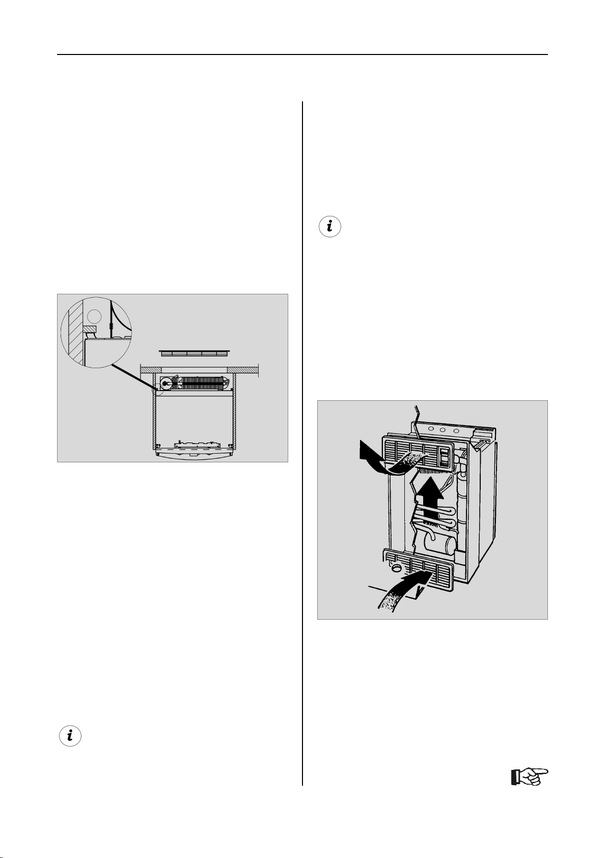
Correct mounting of the lower ventilation grille facilitates access to the connections and
functional parts during maintenance.
CAUTION!
An installation other than described will
reduce the cooling capacity and jeopardise the manufacturer's warranty/product
liability.
14
Page 17
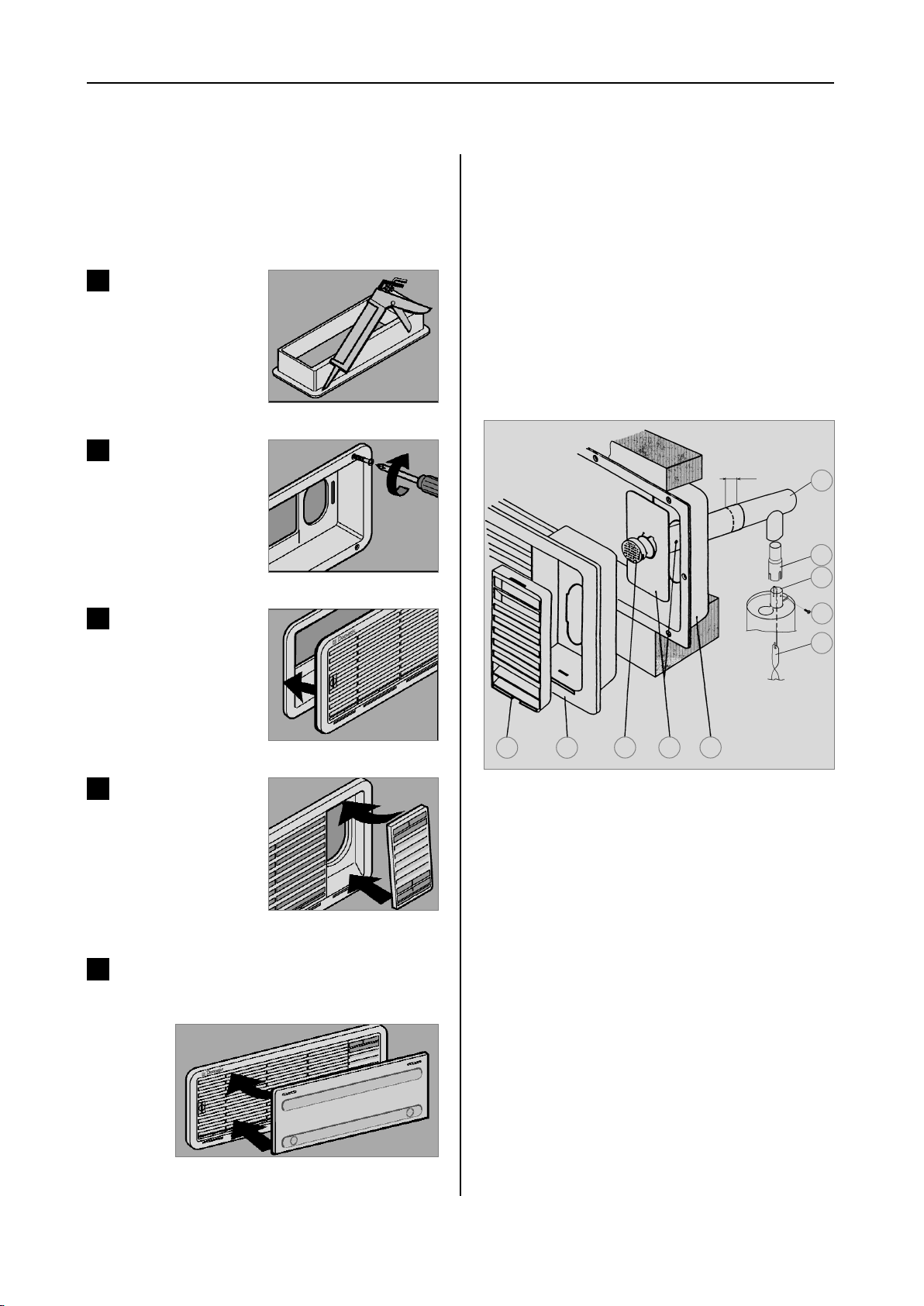
Installation
To install the ventilation grilles, cut two rectangles (451 mm x 156 mm) in the outer wall of
the vehicle (
).
4.2
1
Seal the mounting frame
making it waterproof
(
does not apply for
mounting frames with
integral seal
2
Insert frame and screw
into position
for position of the cuts, see point
).
Fig. 20
Fig. 21
4.4 Exhaust gas duct and installing the fume flue
The exhaust gas duct system must be made in
such a manner as to achieve a complete
extraction of combustion products to the outside of living space. The duct system must
slope in an upward direction in order to avoid
a build-up of condensate. The type of exhaust
gas duct shown in Fig. 25 allows the installation of the winter cover next to (10) (Fig. 25).
min. 15mm
1
2
3
3
Insert and lock ventilation grille.
4
Clip the insert for flue
gas duct in position (
for L100 upper ventilation system kit
5
Insert winter cover.
).
only
Fig. 22
Fig. 23
4
5
10
8
6 79
Fig. 25
Installing the standard fume flue
1. Connect T-piece (1) to adaptor (2) or flue
pipe (3) as required and affix with screw (4).
Ensure that heat baffle (5) is lodged in the correct position.
2. Insert flue pipe with cover plate (6) through
the appropriate aperture in the upper frame (7)
and connect to T-piece (1). If necessary, shorten flue pipe (6) to the required length.
3. Insert and lock ventilation grill LS 100 (8) in
the mounting frame (7).
15
Fig. 24
4. Put cap (9) on flue pipe (6).
5. Insert extractor insert (10) into ventilation
grille (8) .
Page 18
Installation
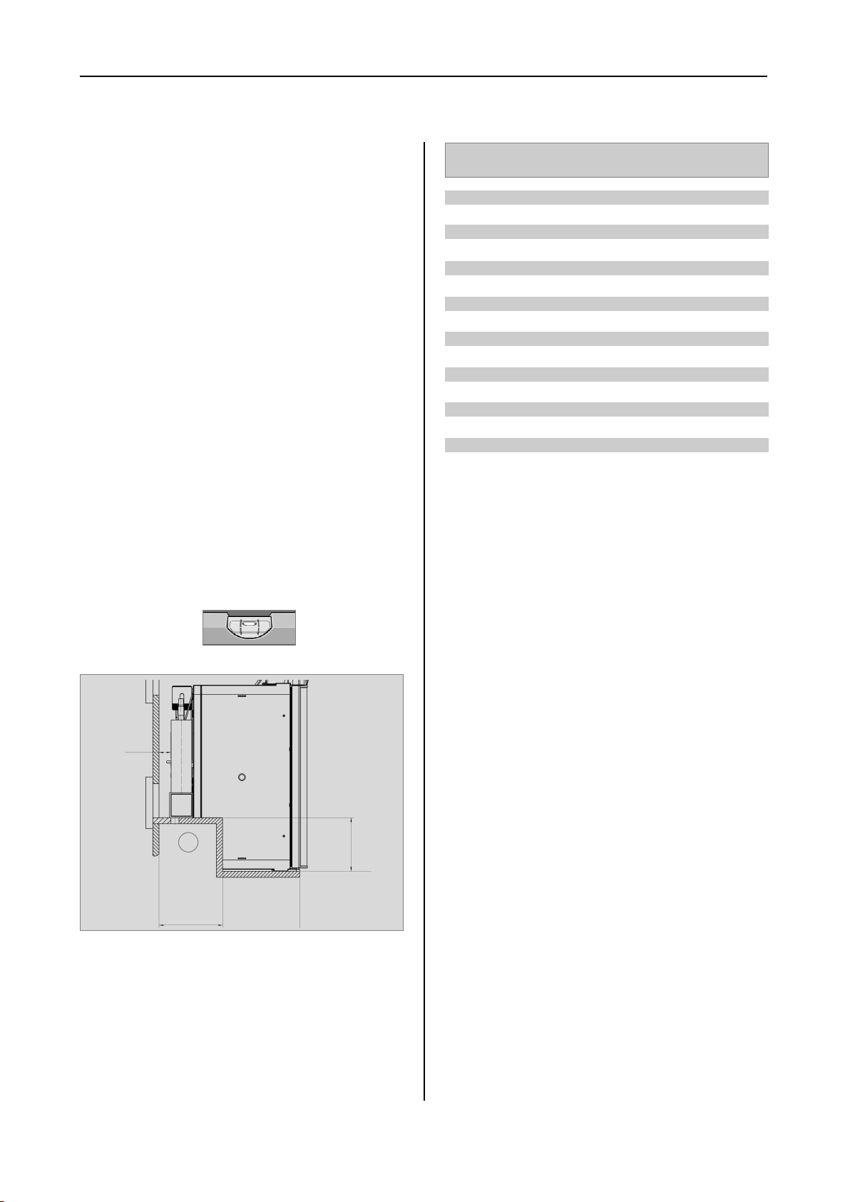
4.5 Installation recess
The refrigerator must be installed draughtproof in a recess (also refer to Section "4.1.4").
The measurements of the recess are stated in
the table below. Step (1) (Fig. 26) is only required for cabinets with a step. The floor of the
recess must be level, allowing the appliance to
be pushed easily into its correct position. The
floor must be substantial enough to bear the
weight of the appliance.
4.5.1 Installation in the recess
Push the appliance far enough into the recess
until the front edge of the refrigerator casing is
aligned with the front of the recess. Allow a
gap of 15-20 mm between the back wall of
the recess and the refrigeration unit.
Ensure that the refrigerator is installed
level in the recess.
Model Height H
RMS 8400
RMS 8401
RMS 8405
RMS 8460
RMS 8461
RMS 8465
RMS 8500
RMS 8501
RMS 8505
RMS 8550
RMS 8551
RMS 8555
RMSL 8550
RMSL 8551
RMSL 8555
220 mm
220 mm
220 mm
220 mm
220 mm
220 mm
220 mm
220 mm
220 mm
220 mm
220 mm
220 mm
220 mm
220 mm
220 mm
ST
Depth T
235 mm
235 mm
235 mm
235 mm
235 mm
235 mm
235 mm
235 mm
235 mm
235 mm
235 mm
235 mm
235 mm
235 mm
235 mm
ST
min
15-20mm
ST
1
ST
T
H
Fig. 26
16
Page 19

Installation
4.6 Securing the refrigerator
In the sidewalls of the refrigerator, there are
four plastic sleeves for securing the refrigerator. The sidewalls or strips attached for securing the refrigerator must be prepared to hold
the screws firmly in place even when under
increased load (while the vehicle is moving).
Fastening screws and caps are supplied with
the refrigerator
4.7 Inserting the decor panel
Model RM 8xxx, RMS 8xxx
Remove the lateral ledge (1) the door
(ledge is attached, not screwed).
Shift decor panel (2) away from the door
and insert the new decor panel. Re-attach
ledge (1).
Fig. 27
CAUTION!
Always insert screws through the sleeves
provided as otherwise components laid in
foam, such as cables etc., could be damaged.
After the refrigerator is put in its final place,
secure the screws into the wall of the recess.
The screws must penetrate the casing of the
refrigerator.
1
2
Decor panel dimensions :
Casing width
Height Width Thickness
743 +/- 0.5 mm 472 +/- 0.5 mm max. 2.2 mm
Casing width
Height Width Thickness
743 +/- 0.5 mm 510.5 +/- 0.5 mm max. 2.2 mm
486 mm
523 mm
Fig. 29
Fig. 28
17
Page 20

Installation
Model RM 8xxx, RMS 84xx
3.
2.
2
1.
2
1.
4.
2.
Fig. 34
1
3
Fig. 30
CAUTION!
Fig. 31
Model RMx(L) 8xxx, frameless decor
panel
1
Fig. 32
4
Decor panel dimensions RML 8xxx :
Casing width
Height Width Thickness
523 mm
Fig. 35
Fig. 36
Fig. 33
1169,5 +0/-1 mm 507,5 +0/-1 mm max. 1.7 mm
18
Page 21

Installation
4.8 Gas installation
WARNING!
The gas connection shall be carried out
by specialised personnel* only.
* Specialised personnel are accredited experts who are
able, by virtue of their training and knowledge, to vouch
for the correct installation and implementation of the leakage test.
Observe the regulations stated in secti-
on 2.1 .
This refrigerator is provided for installati
on within liquid gas equipment in compliance with EN1949 and must be run
exclusively on liquid gas (propane, butane) (no natural gas, town gas).
A fixed, pre-set pressure regulator com-
plying with EN 12864 must be connected
to the liquid gas cylinder.
conformity with EN 1949. A test certificate has to be issued.
The refrigerator must be equipped with a
shut-off valve allowing to cut the supply
line. Such a shut-off device must be
readily accessible to the user.
Connection pressure and gas categories
The refrigerators are operated using the gases
and inlet pressures stated below. The pressure reducing valves between the gas cylinder
and refrigerator to be used must comply with
the categories stated in the following table.
Category Pressure in mbar GAS
The pressure regulator must concur with
the operating pressure specified on the
rating plate of the appliance. The operating pressure corresponds to the standard pressure of the country of specification (EN 1949, EN 732).
Only one connection pressure is permis
sible for any one vehicle! A plate showing the permanent, clearly legible notice must be displayed in full view at the
point where the gas cylinder is installed.
The gas connection to the appliance
must be installed securely and free of
stress using pipe connectors and must
be securely connected to the vehicle (a
hose connection is not permissible) (EN
1949).
The gas connection to the appliance is
effected by means of (Ermeto-) olive
type fitting L8, DIN 2353-ST, complying
with EN 1949 ( s. figure 37, 38).
After professional installation, a leakage
test as well as a flame test have to be
carried out by qualified personnel* in
I3B / P(30) 30 Butane
30 Propane
I3+ (28-30/37) 28-30 Butane
37 Propane
Dometic refrigerators are equipped for a connection pressure of 30 mbar. For connection
to a 50 mbar gas system, use Truma VDR
50/30 medium pressure controller.
When using LPG gas, please consider that the
burner needs cleaning at shorter intervals due
to the gas combustion method (2 - 3 times per
year recommended).
19
Page 22

Installation
Gas connection RM(S) 8xx0 models
SW 17
SW 14
1
(Ermeto-) Olive type fitting L8,
1
(EN ISO 8434)
Gas connection
RM(S) 8xx1, RM(S) 8xx5 models
10 Nm
max
CAUTION!
20 Nm
max
SW 14
SW 17
1
Fig. 37
Fig. 38
20
Page 23

Installation
4.9 Electrical installation
WARNING!
Die elektrische Installation darf nur von
einer autorisierten Fachkraft* ausgeführt
werden.
* Specialised personnel are accredited experts who are
able, by virtue of their training and knowledge, to vouch
for the correct installation.
The electrical installation must be in
accordance with the national regulations
of the respective countries.
The connection cables must be routed in
a way to prevent contact with hot
components of the unit/burner or with
sharp edges.
Changes to the internal electrical instal-
lation or the connection of other electrical components (e.g. external fan) to the
internal wiring of the appliance will render the e1/ CE admittance as well as any
claims from warranty and product liability void!
4.9.1 Mains connection
The power should be supplied by a pro-
perly grounded socket outlet or a grounded non-detachable connection. Where
a socket outlet with mains supply is
used, the outlet must be freely accessible.
Should the connection cable be dama
ged, have it replaced by Dometic
Customer Services or by qualified per
sonnel to avoid hazards.
4.9.2 Battery connection
The machine's 12V connection cable is connected (observing correct polarity) to a terminal strip (RMx 8xx0) or plug-in-contacts (RMx
8xx1, 8xx5). The wiring for the 12V heating
element (refer to A, B wiring diagram connections) must be direct and by the shortest possible route to the battery or electric generator.
o protect the on-board 12 V circuit provide
T
the following fuses:
- RM8xxx, RMS8xxx: 15 A
- RML855x, RMSL855x: 20 A
In order to ensure that the 12V power supply is
shut off when stopping the engine (otherwise
the battery would discharge within a few
hours), perform the power supply to the 12V
heating element (connection A/B in wiring diagram) in a way to have the 12V supply only live
while the vehicle ignition is switched on.
The connection C/D (interior light, electronics)
must be permanently provided by a 12V DC
power supply to be protected by a 2A fuse.
CAUTION!
If the appliance is installed in a caravan
the respective leads for the 12V+ and 12Vconnections A/B and C/D must not be
connected to each other on the caravanside (EN 1648-1).
Cable cross sections and cable lengths :
Motorcaravan & Caravan (inside)
4 mm² (RML 8xxx = 6 mm²)< 6 m
6 mm² (RML 8xxx = 10 mm²)> 6 m
We recommend leading the power supply via
a board-side fuse protection.
Caravan (outside)
min 2,5 mm²(EN1648-1)
21
2,5mm²
Fig. 42
Page 24

Installation
4.9.3 Cable connections
Connections for models RM(S) 8xx0
1
Mains connection
L = brown
1
N = blue
Earth= yellow/green
The power supplies for electronics and heating element are connected directly at the
plug-in contacts of the electronics.
Position of the control electronics :
Fig. 39
on the appliance
B
A
D
C
2
on the vehicle
+
-
12V connection
A = Ground heating element DC (brown)
2
+
-
Fig. 40
B = Positive connection, heating element
DC (brown)
C = Ground interior lighting (black)
D = Positive connection lighting (white)
Connections for models RM(S) 8xxx (MES),
RM(S) 8xx5 (AES) :
For MES and AES it is compulsory to provide a permanent 12V DC supply at the terminals C/D (permanent voltage supply for
functional electronics).
Stepped cabinet models
Standard models
Fig. 41
Fig. 42
22
Page 25

Contacts at the electronics:
Installation
INput heating element
4
(12 V DC)
Earth
2
1
1
Plug-in contacts (manufacturer: Stocko®)
2
Heating element mains
Mains connection (230 V AC)
connection (230 V AC)
OUTput heating
element (12 V DC)
3
-
D+ signal connection
Electronics connection (12 V)
S+ signal connection
3
+
D+/S+
Fig. 43
1
MF 9562-002-80E
2
MF 9562-002-8 OC
3
3-pin with D+ contact:
2-pin :
4
MKH 5132-1-0-200
MF 9562-002-8 ON + spade connector 6.3 x 0.8
MF 9562-003-8 30 960-000-00
23
Page 26

Installation
4.9.4 D+ and solar connection (only
for AES models)
D+ signal connection
In >Automatic Mode< the AES electronic
system automatically selects the most efficient
energy supply. In automatic mode the electronic system uses the D+ signal (dynamo +) of
the alternator to detect 12V DC. 12V DC operation is selected only while the engine is running in order to prevent battery discharge.
S+ signal connection:
12V DC energy can be optionally achieved by
mounting solar equipment to the vehicle. The
solar power equipment must be provided with
a solar charging controller with AES output
(adequate charging controllers available in
selected stores). The "S+ connection (Solar +)
must be connected to the respective terminal
of the solar charging controller (AES output).
The electronic system uses the S+ signal of
the solar charging controller to detect solar
12V DC.
Cable cross-sectional areas:
There are no particularly high current flows via
the D+ and S+ connection; therefore no particularly large cross-section is required for these
connections (approx. 1mm² is sufficient).
24
Page 27

4.9.5 Circuit diagrams
Circuit diagram RM(S) 8xx0 :
Installation
B
A
C
D
25
Fig. 44
Page 28

Installation
Circuit diagram RM(S) 8xx1, RM(S) 8xx5 :
D B
C
A
1
Fig. 45
26
Page 29

Fan (optional) RM(S) 8xx1, RM(S) 8xx5 :
1
= 12V OUT / 12 V power supply for optional connections
1
= Ground connection heating element 12VDC
A
= Positive connection, heating element 12VDC
B
= Ground connection electronics 12VDC
C
= Positive connection electonics 12VDC
D
Fig. 46
For MES and AES it is compulsory to provide
a permanent 12V DC supply at the terminals
C/D (permanent voltage supply for functional
electronics
27
Page 30

Page 31

Deutsch
Einbauanleitung
Absorber-Kühlschrank für Freizeitfahrzeuge
RM 8400 RM 8401 RM 8405 RM 8500 RM 8501 RM 8505 RM 8550 RM 8551 RM 8555
RMS 8400 RMS 8401 RMS 8405 RMS 8460 RMS 8461 RMS 8465 RMS 8500 RMS 8501
RMS 8505 RMS 8550 RMS 8551 RMS 8555 RML 8550 RML 8551 RML 8555 RMSL 8500
RMSL 8501 RMSL 8505
N 1-1
MBA 05/2012
DE
Page 32

Inhaltsverzeichnis
0.0 Auspacken und Transport . . . . . . . . . . . . . . . . . . . . . . . . . . . . . . . . 3
1.0 Allgemeines . . . . . . . . . . . . . . . . . . . . . . . . . . . . . . . . . . . . . . . . . . . 4
1.1 Einleitung . . . . . . . . . . . . . . . . . . . . . . . . . . . . . . . . . . . . . . . . . . . . . . . . . . . . . . . . . . . . . . . . . . 4
1.2 Hinweise zu dieser Bedienungsanleitung . . . . . . . . . . . . . . . . . . . . . . . . . . . . . . . . . . . . . . . . . 4
1.3 Urheberschutz . . . . . . . . . . . . . . . . . . . . . . . . . . . . . . . . . . . . . . . . . . . . . . . . . . . . . . . . . . . . . . 4
1.4 Erklärung der verwendeten Symbole . . . . . . . . . . . . . . . . . . . . . . . . . . . . . . . . . . . . . . . . . . . . . 4
1.5 Gewährleistung . . . . . . . . . . . . . . . . . . . . . . . . . . . . . . . . . . . . . . . . . . . . . . . . . . . . . . . . . . . . . 5
1.6 Haftungsbeschränkung . . . . . . . . . . . . . . . . . . . . . . . . . . . . . . . . . . . . . . . . . . . . . . . . . . . . . . . 5
1.7 Konformitätserklärung . . . . . . . . . . . . . . . . . . . . . . . . . . . . . . . . . . . . . . . . . . . . . . . . . . . . . . . . 5
2.0 Sicherheitshinweise . . . . . . . . . . . . . . . . . . . . . . . . . . . . . . . . . . . . . 6
2.1 Bestimmungsgemäße Verwendung . . . . . . . . . . . . . . . . . . . . . . . . . . . . . . . . . . . . . . . . . . . . . . 6
2.2 Verantwortung des Nutzers . . . . . . . . . . . . . . . . . . . . . . . . . . . . . . . . . . . . . . . . . . . . . . . . . . . . 6
2.3 Arbeiten und Überprüfungen am Kühlschrank . . . . . . . . . . . . . . . . . . . . . . . . . . . . . . . . . . . . . 6
2.4 Betreiben des Kühlschrankes mit Gas . . . . . . . . . . . . . . . . . . . . . . . . . . . . . . . . . . . . . . . . . . . . 6
3.0 Modellbeschreibung . . . . . . . . . . . . . . . . . . . . . . . . . . . . . . . . . . . . 7
3.1 Modellbezeichnung . . . . . . . . . . . . . . . . . . . . . . . . . . . . . . . . . . . . . . . . . . . . . . . . . . . . . . . . . . 7
3.2 Typenschild des Kühlschranks . . . . . . . . . . . . . . . . . . . . . . . . . . . . . . . . . . . . . . . . . . . . . . . . . . 7
3.3 Technische Daten . . . . . . . . . . . . . . . . . . . . . . . . . . . . . . . . . . . . . . . . . . . . . . . . . . . . . . . . . . . . 7
4.0 Einbauanleitung . . . . . . . . . . . . . . . . . . . . . . . . . . . . . . . . . . . . . . . . 10
4.1 Einbau . . . . . . . . . . . . . . . . . . . . . . . . . . . . . . . . . . . . . . . . . . . . . . . . . . . . . . . . . . . . . . . . . . . . 10
4.1.1 Seitlicher Einbau . . . . . . . . . . . . . . . . . . . . . . . . . . . . . . . . . . . . . . . . . . . . . . . . . . . . . . . . . . . . . . . . . . . . . 10
4.1.2 Seitlicher Einbau mit Boden-Dach-Ventilation . . . . . . . . . . . . . . . . . . . . . . . . . . . . . . . . . . . . . . . . . . . . . . 11
4.1.3 Heckeinbau . . . . . . . . . . . . . . . . . . . . . . . . . . . . . . . . . . . . . . . . . . . . . . . . . . . . . . . . . . . . . . . . . . . . . . . . . 11
4.1.4 Zugdichter Einbau . . . . . . . . . . . . . . . . . . . . . . . . . . . . . . . . . . . . . . . . . . . . . . . . . . . . . . . . . . . . . . . . . . . 12
4.2 Be- und Entlüftung des Kühlschranks . . . . . . . . . . . . . . . . . . . . . . . . . . . . . . . . . . . . . . . . . . . . 13
4.3 Einbau der Lüftungssysteme . . . . . . . . . . . . . . . . . . . . . . . . . . . . . . . . . . . . . . . . . . . . . . . . . . . 14
4.4 Abgasführung und Anbringung des Abgaskamins . . . . . . . . . . . . . . . . . . . . . . . . . . . . . . . . . . 15
4.5 Einbaunische . . . . . . . . . . . . . . . . . . . . . . . . . . . . . . . . . . . . . . . . . . . . . . . . . . . . . . . . . . . . . . . 16
4.5.1 Aufstellung in der Nische . . . . . . . . . . . . . . . . . . . . . . . . . . . . . . . . . . . . . . . . . . . . . . . . . . . . . . . . . . . . . . 16
4.6 Kühlschrankbefestigung . . . . . . . . . . . . . . . . . . . . . . . . . . . . . . . . . . . . . . . . . . . . . . . . . . . . . . . 17
4.7 Einsetzen der Dekorplatte . . . . . . . . . . . . . . . . . . . . . . . . . . . . . . . . . . . . . . . . . . . . . . . . . . . . . 17
4.8 Gasinstallation . . . . . . . . . . . . . . . . . . . . . . . . . . . . . . . . . . . . . . . . . . . . . . . . . . . . . . . . . . . . . . 19
4.9 Elektrische Installation . . . . . . . . . . . . . . . . . . . . . . . . . . . . . . . . . . . . . . . . . . . . . . . . . . . . . . . . 20
4.9.1 Netzanschluss . . . . . . . . . . . . . . . . . . . . . . . . . . . . . . . . . . . . . . . . . . . . . . . . . . . . . . . . . . . . . . . . . . . . . . . 20
4.9.2 Batterieanschluss . . . . . . . . . . . . . . . . . . . . . . . . . . . . . . . . . . . . . . . . . . . . . . . . . . . . . . . . . . . . . . . . . . . . 20
4.9.3 Klemmleisten . . . . . . . . . . . . . . . . . . . . . . . . . . . . . . . . . . . . . . . . . . . . . . . . . . . . . . . . . . . . . . . . . . . . . . . 21
4.9.4 D+ und Solaranschluss . . . . . . . . . . . . . . . . . . . . . . . . . . . . . . . . . . . . . . . . . . . . . . . . . . . . . . . . . . . . . . . . 21
4.9.5 Schaltschemata . . . . . . . . . . . . . . . . . . . . . . . . . . . . . . . . . . . . . . . . . . . . . . . . . . . . . . . . . . . . . . . . . . . . . 22
Dometic GmbH
In der Steinwiese 16
D-57074 Siegen
www.dometic.com
© Dometic GmbH - 2011 - Änderungen vorbehalten
2
Page 33

0.0 Auspacken und Transport
Anheben / Tragen des Kühlschranks
VORSICHT!
Nutzen Sie niemals zum Tragen oder Anheben des Kühlschranks andere Teile am Kühlschrank als die in der Abbildung gezeigten ( vor allem nicht das Aggregat, Gasleitungen
und Bedienblende) !
Sie vermeiden Beschädigungen am Kühlschrank !
JA
JA
NEIN
3
Page 34

Allgemeines
1.0 Allgemeines
1.1 Einleitung
Beim Einbau des Gerätes müssen die technischen und administrativen Vorschriften des
Landes, in dem das Fahrzeug zum ersten Mal
zugelassen wird, beachtet werden.
Ansonsten sind die Einbauvorschriften des
Herstellers zu beachten. In Europa z.B. müssen Gasgeräte, Leitungsverlegung, Gasflaschenaufstellung sowie Abnahme und
Dichtheitsprüfung der Europäischen Norm EN
1949 für Flüssiggasanlagen in Fahrzeugen
entsprechen.
1.2 Hinweise zu dieser
Installationsanleitung
Bevor Sie den Kühlschrank einbauen, lesen
Sie diese Installationsanleitung bitte sorgfältig durch.
Diese Anleitung gibt Ihnen die nötigen
Hinweise für den richtigen Einbau Ihres
Kühlschrankes. Beachten Sie besonders die
Sicherheitshinweise. Die Einhaltung der
Hinweise und Handlungsanweisungen ist
wichtig und schützt Sie und den Kühlschrank
vor Schäden. Das Gelesene muss verstanden
worden sein, bevor Sie eine Maßnahme durchführen.
1.4 Erklärung der verwendeten
Symbole
Warnhinweise
Warnhinweise sind durch Symbole gekennzeichnet. Ein ergänzender Text erläutert Ihnen
den Grad der Gefährdung.
Beachten Sie diese Warnhinweise sehr
genau. Damit schützen Sie sich, andere
Personen und das Gerät vor Schäden.
GEFAHR!
GEFAHR kennzeichnet eine unmittelbare
Gefahrensituation, die zum Tod oder einer ernsten Verletzung führen kann, wenn die angegebenen Anweisungen nicht befolgt werden.
WARNUNG!
WARNUNG kennzeichnet eine mögliche
Gefahrensituation, die zum Tod oder einer ernsten Verletzung führen kann, wenn die angegebenen Anweisungen nicht befolgt werden.
VORSICHT!
Bewahren Sie diese Installationsanleitung
sorgfältig auf, sodass sie jederzeit verwendet werden kann.
1.3 Urheberschutz
Die Angaben, Texte und Abbildungen in dieser
Anleitung sind urheberrechtlich geschützt und
unterliegen den gewerblichen Schutzrechten.
Kein Teil dieser Anleitung darf ohne die schriftliche Genehmigung der Dometic GmbH,
Siegen, reproduziert, kopiert oder sonstwie
verwendet werden.
VORSICHT kennzeichnet eine mögliche
Gefahrensituation, die zu leichten oder mittleren Verletzungen führen kann, wenn die angegebenen Anweisungen nicht befolgt werden.
VORSICHT!
VORSICHT ohne Sicherheitssymbol kennzeich-
net eine mögliche Gefahrensituation, die zu
Beschädigungen des Gerätes führen kann,
wenn die angegebenen Anweisungen nicht
befolgt werden.
4
Page 35

Allgemeines
Information
INFORMATION gibt Ihnen ergänzende und
nützliche Hinweise zum Umgang mit Ihrem
Kühlschrank.
Umwelthinweis
UMWELTHINWEIS gibt Ihnen nützliche
Hinweise zur Energieeinsparung und
Entsorgung des Gerätes.
1.6 Haftungsbeschränkung
Alle Angaben und Hinweise in dieser Einbauanleitung wurden unter Berücksichtigung geltender Normen und Vorschriften sowie dem
Stand der Technik erstellt. Dometic behält
sich vor, jederzeit Änderungen am Produkt
vorzunehmen, die im Interesse der
Verbesserung des Produktes und der
Sicherheit angebracht sind.
Dometic übernimmt keine Haftung für
Schäden bei :
Nichtbeachtung dieser Anleitung
nicht bestimmungsgemäßer Verwendung
Verwendung von nicht originalen
Ersatzteilen
Veränderungen und Eingriffen am Gerät
Einwirkung von Umgebungseinflüssen, wie
- Temperaturänderungen
- Luftfeuchtigkeit
1.5 Gewährleistung
Gewährleistungsabwicklungen erfolgen nach
der europäischen Richtlinie 44/1999/EC und
den landesüblichen Bedingungen. Im
Gewährleistungs- oder Servicefall wenden Sie
sich bitte an unseren Kundendienst.
Störungen, die auf fehlerhafte Bedienung
zurückzuführen sind, unterliegen nicht der
Gewährleistung. Jede Veränderung am Gerät
oder die Verwendung von Ersatzteilen, die
keine Original - Dometic - Ersatzteile sind,
sowie das Nichteinhalten der Einbau- und
Bedienungsanleitung führt zum Erlöschen der
Gewährleistung und zum Ausschluss von
Haftungsansprüchen.
1.7 Konformitätserklärung
5
Page 36

Sicherheitshinweise
2.0 Sicherheitshinweise
2.1 Bestimmungsgemäße
Verwendung
GEFAHR!
Dieser Kühlschrank ist für den Einbau in
Freizeitfahrzeuge wie Wohnwagen oder
Reisemobile vorgesehen. Das Gerät ist für
diese Anwendung in Konformität mit der EUGasgeräterichtlinie baumustergeprüft.
Benutzen Sie den Kühlschrank ausschließlich
zum Kühlen und Lagern von Lebensmitteln.
VORSICHT!
Der Kühlschrank darf nicht dem Regen
ausgesetzt werden.
2.2 Verantwortung des Nutzers
Personen, die den Kühlschrank bedienen,
müssen mit dem sicheren Umgang vertraut
sein und die Hinweise der Bedienungsanleitung kennen.
2.3 Arbeiten und Überprüfungen
am Kühlschrank
Überprüfen Sie niemals gasführende Teile
und Leitungen mit einer offenen Flamme auf Undichtigkeit !
Es besteht Brand- oder Explosionsgefahr.
WARNUNG!
Öffnen Sie niemals das Absorberkühlaggregat ! Es steht unter hohem Druck.
Es besteht Verletzungsgefahr!
2.4 Betreiben des Kühlschranks
mit Gas
Der Betriebsdruck muss unbedingt der
Angabe auf dem Typenschild des
Kühlschranks entsprechen. Vergleichen Sie
die Angabe des Betriebsdruckes auf dem
Typenschild mit den Daten des
Druckminderers an der Flüssiggasflasche.
WARNUNG!
Arbeiten an den Gas-, Abgas- und
Elektroeinrichtungen dürfen nur von autorisierten Fachkräften ausgeführt werden.
Durch nicht fachgerechte Maßnahmen
können erhebliche Sach- und/oder
Personenschäden entstehen.
6
Page 37

3.0 Modellbeschreibung
Modellbeschreibung
3.1 Modellbezeichnung
Beispiel :
RM
(S)
(L)
8 4 0 0
1
5
Gerätetiefe :
0 = Standard
5 = + 55mm
6 = + 65mm
4 = Breite 486mm
5 = Breite 523mm
Modellreihe
„Large“
Stufenschrank
3.2 Typenschild des Kühlschranks
Im Inneren des Kühlschranks finden Sie das
Typenschild des Kühlschranks. Es enthält alle
wichtigen Angaben zum Kühlschrank. Dort
können Sie die Modellbezeichnung, die
Produktnummer und Seriennummer ablesen.
Diese Angaben benötigen Sie bei allen
Kontakten mit dem Kundendienst oder der
Ersatzteilbestellung.
1
4
2
5
3
Refrigerator Mobile /
Mobiler Absorberkühlschrank
0
manuelle Energiewahl + manuelle Zündung
(Batteriezünder)
1
manuelle Energiewahl, automatische
Zündung (MES)
5
automatische und manuelle Energiewahl,
automat. Zündung (AES)
Beispiel
Modellnummer
1
Produktnummer
2
Seriennummer
3
Elektrische Anschlusswerte
4
Gasdruck
5
Alle Dometic Kühlschränke sind für den
Anschlussdruck 30 mbar ausgerüstet.
Verwenden Sie bei einem Anschluss an eine
50 mbar-Anlage den Truma Vordruckregler
VDR 50/30.
Abb. 1
7
Page 38

Modellbeschreibung
3.3 Technische Daten
RMS 8xxx
RM 8xxx
T
Modelle mit gebogener Tür
Modell Abmessungen Bruttoinhalt / Bruttoinhalt
RMS 8400
RMS 8401
RMS 8405
RM 8400
RM 8401
RM 8405
RMS 8460
RMS 8461
RMS 8465
RMS 8500
RMS 8501
RMS 8505
RMS 8550
RMS 8551
RMS 8555
RM 8500
RM 8501
RM 8505
RM 8550
RM 8551
RM 8555
RML 8550
RML 8551
RML 8555
RMSL 8500
RMSL 8501
RMSL 8505
H x B x T (mm) mit Frosterfach Netz/Batterie Elektro/Gas gewicht Piezo Automat
Tiefe inkl. Tür Frosterfach entnommen in 24h
821x486x568
821x486x568
821x486x568
821x486x568
821x486x568
821x486x568
821x486x633
821x486x633
821x486x633
821x523x568
821x523x568
821x523x568
821x523x623
821x523x623
821x523x623
821x523x568
821x523x568
821x523x568
821x523x623
821x523x623
821x523x623
1245x523x625
1245x523x625
1245x523x625
1245x523x568
1245x523x568
1245x523x568
80 / 8 lit.
80 / 8 lit.
80 / 8 lit.
90 / 8 lit.
90 / 8 lit.
90 / 8 lit.
90 / 11 lit.
90 / 11 lit.
90 / 11 lit.
90 / 9 lit.
90 / 9 lit.
90 / 9 lit.
103 /12 lit.
103 /12 lit.
103 /12 lit.
100 / 9 lit.
100 / 9 lit.
100 / 9 lit.
115 /12 lit.
115 /12 lit.
115 /12 lit.
179 /33 lit.
179 /33 lit.
179 /33 lit.
145 /28 lit.
145 /28 lit.
145 /28 lit.
85 lit.
85 lit.
85 lit.
95 lit.
95 lit.
95 lit.
96 lit.
96 lit.
96 lit.
96 lit.
96 lit.
96 lit.
110 lit.
110 lit.
110 lit.
106 lit.
106 lit.
106 lit.
122 lit.
122 lit.
122 lit.
189 lit.
189 lit.
189 lit.
155 lit.
155 lit.
155 lit.
B
Anschlusswerte
125 W / 120 W
125 W / 120 W
125 W / 120 W
135 W / 130 W
135 W / 130 W
135 W / 130 W
125 W / 120 W
125 W / 120 W
125 W / 120 W
125 W / 120 W
125 W / 120 W
125 W / 120 W
125 W / 120 W
125 W / 120 W
125 W / 120 W
135 W / 130 W
135 W / 130 W
135 W / 130 W
135 W / 130 W
135 W / 130 W
135 W / 130 W
190 W / 170 W
190 W / 170 W
190 W / 170 W
190 W / 170 W
190 W / 170 W
190 W / 170 W
RML 8xxx
H
Abb. 3Abb. 2
Verbrauch * Netto- Zündung
ca.2,5 KWh / 270 g
ca.2,5 KWh / 270 g
ca.2,5 KWh / 270 g
ca.2,4 KWh / 270 g
ca.2,4 KWh / 270 g
ca.2,4 KWh / 270 g
ca.2,5 KWh / 270 g
ca.2,5 KWh / 270 g
ca.2,5 KWh / 270 g
ca.2,5 KWh / 270 g
ca.2,5 KWh / 270 g
ca.2,5 KWh / 270 g
ca.2,6 KWh / 270 g
ca.2,6 KWh / 270 g
ca.2,6 KWh / 270 g
ca.2,4 KWh / 270 g
ca.2,4 KWh / 270 g
ca.2,4 KWh / 270 g
ca.2,6 KWh / 270 g
ca.2,6 KWh / 270 g
ca.2,6 KWh / 270 g
ca.3,2 KWh / 380 g
ca.3,2 KWh / 380 g
ca.3,2 KWh / 380 g
ca.3,2 KWh / 380 g
ca.3,2 KWh / 380 g
ca.3,2 KWh / 380 g
25 kg
25 kg
25 kg
27 kg
27 kg
27 kg
26 kg
26 kg
26 kg
26 kg
26 kg
26 kg
27 kg
27 kg
27 kg
28 kg
28 kg
28 kg
30 kg
30 kg
30 kg
45 kg
45 kg
45 kg
40 kg
40 kg
40 kg
Abb. 4
•
•
•
•
•
•
•
•
•
•
•
•
•
•
•
•
•
•
•
•
•
•
•
•
•
•
•
8
Page 39

Modelle mit flacher Tür
Modellbeschreibung
Modell Abmessungen Bruttoinhalt / Bruttoinhalt
RMS 8500
RMS 8501
RMS 8505
RMS 8550
RMS 8551
RMS 8555
RM 8500
RM 8501
RM 8505
RM 8550
RM 8551
RM 8555
H x B x T (mm) mit Frosterfach Netz/Batterie Elektro/Gas gewicht Piezo Automat
Tiefe inkl. Tür Frosterfach entnommen in 24h
821x523x541
821x523x541
821x523x541
821x523x596
821x523x596
821x523x569
821x523x541
821x523x541
821x523x541
821x523x596
821x523x596
821x523x596
86 / 9 lit.
86 / 9 lit.
86 / 9 lit.
99 /12 lit.
99 /12 lit.
99 /12 lit.
96 / 9 lit.
96 / 9 lit.
96 / 9 lit.
111 /12 lit.
111 /12 lit.
111 /12 lit.
92 lit.
92 lit.
92 lit.
106 lit.
106 lit.
106 lit.
102 lit.
102 lit.
102 lit.
118 lit.
118 lit.
118 lit.
Anschlusswerte
125 W / 120 W
125 W / 120 W
125 W / 120 W
125 W / 120 W
125 W / 120 W
125 W / 120 W
135 W / 130 W
135 W / 130 W
135 W / 130 W
135 W / 130 W
135 W / 130 W
135 W / 130 W
Verbrauch * Netto- Zündung
ca.2,5 KWh / 270 g
ca.2,5 KWh / 270 g
ca.2,5 KWh / 270 g
ca.2,6 KWh / 270 g
ca.2,6 KWh / 270 g
ca.2,6 KWh / 270 g
ca.2,4 KWh / 270 g
ca.2,4 KWh / 270 g
ca.2,4 KWh / 270 g
ca.2,6 KWh / 270 g
ca.2,6 KWh / 270 g
ca.2,6 KWh / 270 g
26 kg
26 kg
26 kg
27 kg
27 kg
27 kg
28 kg
28 kg
28 kg
30 kg
30 kg
30 kg
•
•
•
•
•
•
•
•
•
•
•
•
Technische Änderungen vorbehalten.
*Durchschnittsverbrauch gemessen bei einer durchschnittlichen Umgebungstemperatur von 25°C in Anlehnung an ISO-
Standard.
9
Page 40

Einbau
4.0 Einbauanleitung
4.1 Einbau
WARNUNG!
Die Installation des Gerätes darf nur von
autorisiertem Fachpersonal erfolgen!
Das Gerät und die Abgasführung müssen
grundsätzlich so eingebaut werden, dass es
für Servicearbeiten gut zugänglich ist, leicht
aus- und eingebaut und ohne großen Aufwand
aus dem Fahrzeug entnommen werden kann.
Bei der Aufstellung und dem Anschluss des
Gerätes sind folgende Bestimmungen zu
beachten:
Die elektrische Installation muss nach
den nationalen und örtlichen Vorschiften
erfolgen.
Die Gas-Installation muss nach den
nationalen und örtlichen Vorschiften
erfolgen.
4.1.1 Seitlicher Einbau
Wird das Gerät auf der Seite der Eingangstür
eingebaut, ist darauf zu achten, dass die
Belüftungsgitter nicht durch die aufstehende
Tür zugedeckt werden. (
Belüftungsgitter min. 25 mm). Ansonsten entsteht eine eingeschränkte Belüftung, die zu
Kühlleistungsverlusten führt. Die Türseite des
Fahrzeugs wird oft mit einem Vorzelt versehen.
Dadurch wird die Ableitung von
Verbrennungsgasen und Wärme durch die
Lüftungsgitter erschwert (Kühlleistungsverlust entsteht)!
(Abb.5) Die Lüftungsgitter sind abgedeckt. Der
Abstand zwischen der Tür und den
Lüftungsgittern muss min. 25 mm betragen!
Bei Abständen Tür/Gitter zwischen 25 mm
und 45 mm empfehlen wir den Einbau des
Dometic Lüfterkits (
) , um eine optimale Kühlleistung bei
00/0
hohen Umgebungstemperaturen zu erreichen.
Abb. 5
Artikel-Nr. 241 2985 -
Abstand Tür -
Europäische Norm EN 1949
Europäische Norm EN 60335-1,
EN 60335-2-24, EN 1648-1 , EN 1648-2
Installieren Sie das Gerät geschützt
gegen übermässige Wärmeeinstrahlung.
Überhöhte Wärmeeinstrahlung führt zu Leistungseinbußen und erhöhtem Energieverbrauch des Kühlschrankes !
Abweichungen von dieser Einbauanweisung ohne vorherige Freigabe von Dometic
führen zum Erlöschen der Gewährleistung
seitens der Dometic GmbH !
Abb. 5
(Abb. 6) Die Lüftungsgitter bieten auch bei
geöffneter Tür einen ungehinderten Austritt
der Aggregatwärme und der Abgase.
Lüftungsgitter frei !
OK!
10
Abb. 6
Page 41

4.1.2 Seitlicher Einbau mit BodenDach-Ventilation
Einbau
Eine weitere Möglichkeit ist, die Ventilation
des Kühlschranks über eine
Belüftungsöffnung im Boden und eine
Entlüftungseinrichtung auf dem Dach des
Fahrzeugs herbeizuführen (siehe Abb. 7).
Zwischen Oberkante Kühlschrank und
Dachentlüftung muss ein Kamin eingerichtet
sein, der die Warmluft und ggf. die Abgase des
Kühlschrankaggregates direkt zur Dachentlüftung leitet.
Die Bodenöffnung muss einen freien
Querschnitt von mindestens 250 cm² aufweisen. Die Öffnung muss mit einem Schutz, z.B.
Prellblech und Netz, versehen sein, um den
Eintritt von Schmutz in den Gasbrennerbereich zu verhindern. Bei dieser Belüftungsweise kann im Vergleich zur seitlichen
Belüftung mehr Schmutz in den rückwärtigen
Bereich des Kühlschranks eindringen, sodass
eine regelmäßige Wartung des Gasbrenners,
mind. einmal im Jahr, vorzusehen ist.
Bei dieser Einbauvariante ist die regelmäßige Wartung der Gasbrennereinheit nur
nach Ausbau des Gerätes möglich. Der
Kühlschrank muss zwingend in der Weise
installiert sein, dass ein leichter Ausbau
gewährleistet ist.
Wir empfehlen daher, eine Wartungsöffnung (Serviceklappe) an der Außenseite
vorzusehen.
4.1.3 Heckeinbau
Der Heckeinbau führt oftmals zu einer ungünstigen Einbausituation, da die optimale Beund Entlüftung nicht immer gewährleistet ist
(z.B. wird das untere Lüftungsgitter durch den
Stoßfänger oder die Rückleuchten des
Fahrzeuges verdeckt !) (
Abb. 8
Kühlleistung des Aggregates ist effektiv nicht
verfügbar.
). Die maximale
Empfehlung:
Dachentlüfter
R500
Warmluft
Kondensator
Bodenöf
min. 50 mm breit
min. 520 mm lang
fnung:
Abb. 7
Lüftungsgitter
nicht frei !
Abb. 8
Lüftungsgitter
frei ! OK!
Abb. 9
Eine ungünstige Variante des Heckeinbaus ist
die seitliche Anbringung der Be- und
Entlüftungsgitter (
Abb. 10
). Die Luft- Wärme Umwälzung ist sehr eingeschränkt, wodurch
die Wärmetauscher (Kondenser, Absorber)
nicht mehr ausreichend gekühlt werden. Auch
die Variante mit einem zusätzlich im Boden
montierten Belüftungsgitter weist hier eine
schlechte Luftstromführung auf.
11
Page 42

Einbau
WARNUNG!
In keinem Fall soll der zugdichte Einbau
des Kühlschranks mit dauerhaftenden
Dichtungsmassen oder Verschäumung
(z.B. Montageschaum) o. ä. erfolgen!
Verwenden Sie KEINE leicht entflammbaren Materialien (besonders SilikonDichtungsmasse oder ähnliches) zur
Abdichtung, es besteht Brandgefahr! Bei
deren Verwendung erlischt die Produkthaftung und Gewährleistung des
Geräteherstellers.
Abb. 10
VORSICHT!
Die maximale Kühlleistung ist nicht verfügbar! Wenden Sie diese Einbaumöglichkeit nicht an, da bei dieser Einbausituation die Be- und Entlüftung wie unter
Punkt 4.2 beschrieben nicht gewährleistet ist!
4.1.4 Zugdichter Einbau
Kühlgeräte in Wohnwagen, Reisemobilen oder
sonstigen Fahrzeugen müssen zugdicht eingebaut sein (EN 1949). Das bedeutet, dass die
Verbrennungsluft für den Gasbrenner nicht aus
dem Wohnraum entnommen wird und die
Abgase am direkten Eintritt in den Wohnraum
gehindert werden.
Es muss eine geeignete Abdichtung zwischen
dem rückseitigen Bereich des Kühlschranks
und dem Fahrzeuginnenraum vorgesehen
werden.
Vorschlag 1
Die Lippendichtungen (1) werden in der
Einbaunische unten und jeweils seitlich angebracht (Abb. 11-13). Ein Wärmeableitblech (2)
wird in der Einbaunische oberhalb des Kühlschranks befestigt (NICHT am Kühlschrank
befestigen).
Bringen Sie das Ableitblech so an, dass die
erwärmte Luft durch das obere Lüftungsgitter
ins Freie entweicht und kein Wärmestau entstehen kann.
2
Abb. 12
1
2
Dometic empfiehlt dringend, dies mittels einer
flexiblen Dichtung auszuführen, um einen späteren Aus- und Einbau des Gerätes zu
Wartungszwecken zu vereinfachen.
12
1
Abb. 11
Abb. 13
Page 43

Einbau
Der Kühlschrank wird später von vorne in die
Einbaunische eingeschoben. Achten Sie darauf, dass die Dichtungen gleichmäßig am
Gehäuse anliegen.
Der Ausbau des Kühlschranks zur Wartung
und Reparatur ist so leicht möglich.
Vorschlag 2
Befestigen Sie die Dichtlippen an einer rückseitigen Anschlagsleiste (1), z.B. durch
Kleben.
1
4.2 Be- und Entlüftung des
Kühlschranks
Der korrekte Einbau des Gerätes ist für die
Funktion wichtig, da sich auf der Rückseite
des Gerätes, physikalisch bedingt, Wärme
entwickelt, die ins Freie abgeleitet werden
muss.
Bei hohen Umgebungstemperaturen ist die
volle Leistung des Kühlaggregates nur
durch eine ausreichende Be- und Entlüftung gewährleistet.
Die Belüftung des Aggregates erfolgt durch
zwei Öffnungen (Belüftungsgitter) in der
Fahrzeugwand. Frischluft tritt unten ein,
erwärmt sich und strömt durch das obere
Belüftungsgitter ab (Kamineffekt).
Abb. 14
Der Raum, der sich zwischen Fahrzeugaussenwand und Kühlschrank befindet, ist gegenüber dem Wohnbereich abgedichtet. Es können keine Abgase in den Wohnbereich eindringen. Die Abgase entweichen durch das obere
Gitter der Be- und Entlüftung ins Freie. Es ist
beim zugdichten Einbau nicht erforderlich,
eine spezielle Abgasführung einzusetzen.
Bei dieser Einbauweise kann oben wie unten
das gleiche Lüftungsgitter LS200 ohne
Abgasführung eingesetzt werden.etic-Dicht-
Sollte dennoch ein Abgaskamin gewünscht
werden, bauen Sie in die obere Belüftungsöffnung das Belüftungssystem LS100 mit Abgasführung ein (
Abweichungen bedürfen der Zustimmung
des Herstellers !
Einbau Abgaskamin siehe "4.4"
) .
Abb. 15
Das obere Belüftungsgitter sollte so hoch
wie möglich über dem Kühlaggregat angebracht werden (1, Abb. 16) . Das untere
Belüftungsgitter muss bündig mit dem
Nischenboden angeordnet sein (Abb.
16,17), damit unverbranntes Gas (schwerer
als Luft) auf direktem Weg ins Freie gelangt.
13
Page 44

Einbau
4.3 Einbau der Lüftungssysteme
1
1
2
2
Lüftungsgitter LS 100 oder LS 200
1
2
Lüftungsgitter LS 200
Abb. 16
Das obere Lüftungssystem LS 100 besteht
aus einem Einbaurahmen (RS 1640) (1), einem
Lüftungsgitter inkl. Abgasführung (AS 1620)
(2, 3) und einer Winterabdeckung (WA120) (4).
Das untere Lüftungssystem LS 200 besteht
ebenfalls aus einem Einbaurahmen (RS 1650),
Lüftungsgitter (AS 1630, jedoch ohne
Abgasführung) und einer Winterabdeckung
(WA130).
LS 100
1
2
4
3
Der Gasbrenner muss sich oberhalb der
Kante (1, Abb. 17) befinden.
1
Abb. 17
Wenn diese Anordnung nicht möglich ist,
muss der Fahrzeughersteller eine Entlüftungsöffnung im Nischenboden herstellen,
damit unverbranntes Gas sich nicht am
Boden sammelt.
Die Belüftungsgitter müssen einen freien
Querschnitt von mindestens 250 cm² aufweisen. Dies wird mit dem Dometic Absorber
Be- und Entlüftungssystemen LS 100 / LS 200
erreicht, die für diesen Zweck geprüft und
zugelassen sind.
Abb. 18
LS 200
Abb. 19
Die korrekte Anbringung des unteren Lüftungsgitters erleichtert den Zugang zu
Geräteanschlüssen und Funktionsteilen bei
Wartungsarbeiten.
VORSICHT!
Eine abweichende Installation vermindert
die Kühlleistung und gefährdet die
Gewährleistung/Produkthaftung.
14
Page 45

Einbau
Zum Einbau der Belüftungsgitter werden zwei
rechteckige Ausschnitte in der Größe von 451
mm x 156 mm in der Fahrzeugaußenwand
angebracht (
4.2
).
1
Einbaurahmen wasserundurchlässig abdichten
(
entfällt beim
Einbaurahmen mit integrierter Dichtung
2
Rahmen einsetzen und
festschrauben.
Lage der Ausschnitte siehe Pkt.
).
Abb. 20
Abb. 21
4.4 Abgasführung und
Anbringen des Abgaskamins
Die Abgasführung muss so gestaltet sein,
dass die vollständige Ableitung der Verbrennungsprodukte nach außerhalb des Wohnraumes sichergestellt ist. Die Abgasleitung
muss stetig steigend geführt werden, um eine
Ansammlung von Kondensat zu vermeiden.
Bei der in Abb. 25 gezeigten Art der
Abgasführung wird die Winterabdeckung seitlich (10) (Abb. 25) angebracht.
min. 15mm
1
2
3
3
Lüftungsgitter einsetzen
und verriegeln.
4
Einsatz für Abgasführung
einclipsen (
rem Entlüftungssystem
LS100
5
Winterabdeckung einsetzen.
nur bei obe-
).
Abb. 22
Abb. 23
Abb. 24
4
5
10
8
6 79
Abb. 25
Anbringen des Standardabgaskamins
1. T-Stück (1) auf den Adapter (2), bzw. auf
das Abgasrohr (3) aufstecken und mit der
Schraube (4) fixieren. Dabei ist darauf zu achten, dass der Heizverteiler (5) in der dafür vorgesehenen Position sitzt.
2. Abgasrohr kpl. mit Abdeckplatte (6) durch
die dafür vorgesehene Öffnung des oberen
Rahmens (7) stecken und mit dem T-Stück (1)
verbinden. Abgasrohr (6) eventuell auf richtige
Länge kürzen.
3. Lüftungsgitter LS 100 (8) in den Einbaurah-
men (7) einsetzen und verriegeln.
4. Abdeckkappe (9) auf das Abgasrohr (6)
stecken.
5. Einsatz für Abgasführung (10) in das
Lüftungsgitter (8) einsetzen.
15
Page 46

Einbau
4.5 Einbaunische
Der Kühlschrank muss in eine Nische zugdicht eingebaut werden (s.a. "4.1.4"). Die
Stufe (1) (Abb. 26) wird nur bei
Stufenschränken benötigt. Der Nischenboden
muss eben sein, sodass das Gerät sich leicht
in seine richtige Lage einschieben lässt. Der
Boden muss genügend Festigkeit haben um
das Gewicht des Gerätes tragen zu können.
4.5.1 Aufstellen in der Nische
Das Gerät wird in die Nische soweit eingeschoben, bis Vorderkante des Kühlschrankgehäuses und Vorderkante Nische fluchten.
Zwischen Nischenrückwand und Kühlschrankaggregat sollen 15-20 mm Freiraum
sein!
Der Kühlschrank muss waagerecht in die
Nische eingebaut werden.
Modell Höhe H
RMS 8400
RMS 8401
RMS 8405
RMS 8460
RMS 8461
RMS 8465
RMS 8500
RMS 8501
RMS 8505
RMS 8550
RMS 8551
RMS 8555
RMSL 8550
RMSL 8551
RMSL 8555
220 mm
220 mm
220 mm
220 mm
220 mm
220 mm
220 mm
220 mm
220 mm
220 mm
220 mm
220 mm
220 mm
220 mm
220 mm
ST
Tiefe T
235 mm
235 mm
235 mm
235 mm
235 mm
235 mm
235 mm
235 mm
235 mm
235 mm
235 mm
235 mm
235 mm
235 mm
235 mm
ST
min
15-20mm
ST
1
ST
T
H
Abb. 26
16
Page 47

Einbau
4.6 Kühlschrankbefestigung
In den Seitenwänden des Kühlschrankes sind
vier Kunststoffbuchsen zur Befestigung des
Kühlschrankes vorgesehen. Die Seitenwände
oder die zur Kühlschrankbefestigung angebrachten Leisten müssen so ausgelegt sein,
dass die Schrauben auch bei erhöhter
Beanspruchung (während der Fahrt) fest sitzen. Befestigungsschrauben und Abdeckkappen liegen dem Kühlschrank bei.
4.7 Einsetzen der Dekorplatte
Modell RM 8xxx, RMS 84xx
Ziehen Sie die seitliche Leiste (1) der Tür ab
( Leiste ist aufgesteckt, nicht verschraubt)
Schieben Sie die Dekorplatte (2) in die Tür
ein und stecken Sie die Leiste (1) wieder
auf.
Abb. 27
VORSICHT!
Schrauben immer durch die dafür vorgesehenen Buchsen drehen, da ansonsten
eingeschäumte Bauteile wie Leitungen u.
a. beschädigt werden können.
Nachdem der Kühlschrank in seine endgültige
Lage gebracht ist, werden die Schrauben
durch das Gehäuse des Kühlschrankes in die
Nischenwand geschraubt.
1
2
Abmessungen der Dekorplatte :
Gehäusebr
Höhe Breite Dicke
743 +/- 0.5 mm 472 +/- 0.5 mm max. 2.2 mm
Gehäusebr
Höhe Breite Dicke
743 +/- 0.5 mm 510.5 +/- 0.5 mm max. 2.2 mm
eite 486 mm
523 mm
eite
Abb. 29
Abb. 28
17
Page 48

Einbau
Modell RM 8xxx, RMS 84xx
3.
2.
2
1.
2
1.
4.
2.
Abb. 34
1
3
Abb. 30
VORSICHT!
Abb. 31
Modell RMx(L) 8xxx, rahmenlose
Dekorplatte
1
Abb. 32
Abb. 35
4
Abb. 36
Abmessungen der Dekorplatte RML 8xxx:
Gehäusebr
Höhe Breite Dicke
eite 525 mm
Abb. 33
1169,5 +0/-1 mm 507,5 +0/-1 mm max. 1.7 mm
18
Page 49

Einbau
4.8 Gasinstallation
WARNUNG!
Der Gasanschluss darf nur von einer autorisierten Fachkraft* ausgeführt werden.
* Autorisierte Fachkräfte sind anerkannte Sachkundige,
die aufgrund ihrer Ausbildung und Kenntnisse die
Gewähr dafür bieten, dass die Installation und die
Dichtheitsprüfung ordnungsgemäß durchgeführt wird.
Beachten Sie die in Punkt 2.1 aufgeführ-
ten Bestimmungen !
Dieser Kühlschrank ist für eine
Installation in eine Flüssigasanlage nach
EN1949 vorgesehen und muss ausschließlich mit Flüssiggas (Propan,
Butan) betrieben werden (kein Erdgas,
Stadtgas) .
gemäß EN 1949 von einer autorisierten
Fachkraft* durchzuführen. Über die
Prüfung ist eine Bescheinigung auszu stellen.
Der Kühlschrank muss durch eine Ab-
sperreinrichtung in der Zuführungsleitung absperrbar sein. Die Absperreinrichtung muss für den Benutzer leicht
zugänglich angebracht werden.
Anschlussdruck und Gaskategorien
Die Kühlschränke werden mit den nachfolgend angegebenen Gasen und Einlassdrükken betrieben. Die zwischen Gasflasche und
Kühlschrank einzusetzenden Druckminderer
müssen den in der nachfolgenden Tabelle
angegebenen Kategorien entsprechen.
Ein fest eingestellter Druckregler nach
EN 12864 ist an dem Flüssiggasbehälter
anzuschliessen.
Der Druckregler muss mit dem auf dem
Typenschild des Gerätes angegebenen
Betriebsdruck übereinstimmen. Der Betriebsdruck entspricht dem Normdruck
des Bestimmungslandes (EN 1949, EN
732).
Für ein Fahrzeug ist nur ein einheitlicher
Anschlussdruck zulässig! Ein Hinweisschild mit dem dauerhaften, gut lesbaren
Hinweis auf den Betriebsdruck ist am
Aufstellungsort der Gasflasche gut
sichtbar anzubringen.
Der Gasanschluss zum Gerät muss mit
Rohranschlussleitungen fest und spannungsfrei installiert und mit dem Fahrzeug fest verbunden sein (Schlauchanschluss ist unzulässig) ( EN 1949 ).
Der Gasanschluss am Gerät erfolgt mit
tels einer Schneidring- (Ermeto-)
Verschraubung L8, DIN 2353-ST nach EN
1949 (siehe Abb. 37,38).
Nach fachgerechter Installation ist eine
Dichtheitsprüfung und eine Flammprobe
Kategorie Druck in mbar GAS
I3B / P(30) 30 Butan
30 Propan
I3+ (28-30/37) 28-30 Butan
37 Propan
Dometic Kühlschränke dieser Serie sind für
den Anschlussdruck 30 mbar ausgerüstet.
Verwenden Sie bei einem Anschluss an eine
50 mbar-Anlage den Truma Vordruckregler
VDR 50/30.
Bei der Verwendung von Autogas ist zu
beachten, dass aufgrund der Art der
Verbrennung des Gases der Brenner häufiger
gereinigt werden muss ( 2-3 Mal im Jahr empfohlen).
19
Page 50

Einbau
Gasanschluss Modelle RM(S)(L) 8xx0
SW 17
SW 14
1
Schneidring- (Ermeto-) Verschraubung L8,
1
DIN 2353-ST (EN ISO 8434)
Gasanschluss
Modelle RM(S)(L) 8xx1, RM(S)(L) 8xx5
10 Nm
max
VORSICHT!
20 Nm
max
SW 14
SW 17
1
Abb. 37
Abb. 38
20
Page 51

Einbau
4.9 Elektrische Installation
WARNUNG!
Die elektrische Installation darf nur von
einer autorisierten Fachkraft* ausgeführt
werden.
* Autorisierte Fachkräfte sind anerkannte Sachkundige,
die aufgrund ihrer Ausbildung und Kenntnisse die
Gewähr dafür bieten, dass die Installation ordnungsgemäß durchgeführt wird.
Die elektrische Installation muss nach
den nationalen Ländervorschriften erfolgen.
Die Anschlusskabel müssen so verlegt
sein, dass sie mit heissen Teilen des
Aggregates / Brenners oder mit scharfen
Kanten nicht in Berührung kommen.
Veränderungen an der internen elektri-
schen Installation oder der Anschluss
anderer elektrischer Komponenten (z. B.
fremder Zusatzlüfter) an der internen
Verkabelung des Gerätes führen zum
Erlöschen der e1/CE - Zulassung sowie
jeglicher Ansprüche aus Gewährleistung
und Produkthaftung !
4.9.2 Batterieanschluss
Das bordseitige 12V-Anschlusskabel wird an
eine Klemmleiste (RMx 8xx0) oder an
Steckkontakten (RMx 8xx1, 8xx5) am
Kühlschrank polrichtig angeschlossen. Die
Verkabelung für das 12V-Heizelement (s.
Schaltbild Anschluss A, B) sollte mit einer
direkten, möglichst kurzen Verbindung an die
Batterie bzw. Lichtmaschine erfolgen.
Bordseitig ist der 12-V-Stromkreis mit
folgenden Sicherungen abzus
- RM8xxx, RMS8xxx: 15 A
- RML855x, RMSL855x: 20 A
Damit beim Abstellen des Fahrzeugmotors
nicht vergessen wird, den 12V-Betrieb auch
auszuschalten (die Batterie würde in wenigen
Stunden entladen), ist die Stromversorgung für
das 12V-Heizelement (s. Schaltbild Anschluss
A/B) so auszuführen, dass sie beim Umdrehen
des Zündschlüssels unterbrochen wird.
An dem Anschluss C/D (s. Schaltbild
Anschluss Beleuchtung, Elektronik) muss eine
12V-Dauerversorgung anliegen, die bordseitig
mit einer 2A - Sicherung abgesichert sein
muss.
VORSICHT!
ichern:
4.9.1 Netzanschluss
Die Stromversorgung muss an eine vor-
schriftsmäßig geerdete Steckdose oder
an einen geerdeten Festanschluss erfolgen. Wird die Netzanschlussleitung mit
Stecker verwendet, muss der Stecker
frei zugänglich sein.
Wenn die Anschlussleitung beschädigt
wird, muss sie durch den Kundendienst
von Dometic oder durch ebenso qualifiziertes Personal ersetzt werden, um
Gefährdungen zu vermeiden.
Wir empfehlen, die Zuleitung über eine bordseitige Absicherung zu führen.
Bei Installation im Caravan dürfen caravanseitig die jeweiligen Minus- und
Plusleitungen der 12V-Anschlüsse A/B
und C/D nicht miteinander verbunden
werden ( EN 1648-1).
Leitungsquerschnitte / Leitungslängen :
Motorcaravan & Caravan (innerhalb)
4 mm² (RML 8xxx = 6 mm²)< 6 m
6 mm² (RML 8xxx = 10 mm²)> 6 m
Caravan (außerhalb)
min 2,5 mm²(EN1648-1)
2,5mm²
Abb. 42
21
Page 52

Einbau
4.9.3 Kabelanschlüsse
Anschlüsse bei Modellen RM(S) 8xx0 :
1
Netzanschluss
L = braun
1
N = blau
Erdung = gelb/grün
Der Anschluss der Spannungsversorgungen
für Elektronik und Heizelemente erfolgt direkt
an den Steckkontakten der Elektronik.
Position der Steuerelektronik :
Abb. 39
geräteseitig
B
A
D
C
2
fahrzeugseitig
+
-
12V-Anschluss
A = Masse Heizelement DC (braun)
2
+
-
Abb. 40
B = Plus Heizelement DC (braun)
C = Minus Beleuchtung (schwarz)
D = Plus Beleuchtung (weiß)
Anschlüsse bei Modellen RM(S) 8xxx (MES),
RM(S) 8xx5 (AES) :
Zum Betrieb der Gerätetypen MES und AES
ist es unerlässlich, eine 12V DC
Dauerversorgung an den Klemmen C/D
anzuschließen (Dauerversorgung für die
Funktionselektronik).
Stufenschrankmodelle
Standardmodelle
Fig. 41
Fig. 42
22
Page 53

Kontakte an der Elektronik :
Erdung
Einbau
EINGANG
Heizelement (12V-)
4
AUSGANG
Heizelement (12V-)
2
1
1
Steckkontakte (Hersteller : Stocko®)
1
MF 9562-002-80E
2
MF 9562-002-8 OC
3
3-polig mit D+ - Kontakt :
2-polig :
2
Heizelement Netz (230V~)
Anschluss Netz (230V~)
MF 9562-003-8 30 960-000-00
MF 9562-002-8 ON + Flachstecker 6.3 x 0.8
3
Anschluss D+ Signal
Anschluss Elektronik (12V)
Anschluss S+ Signal
-
3
+
D+/S+
Abb. 43
4
MKH 5132-1-0-200
23
Page 54

Einbau
4.9.4 D+ und Solaranschluss (nur bei
AES-Modellen)
D+ - Anschluss:
Im >Automatic mode< wählt die AES-
Elektronik automatisch die günstigste vorhandene Energieart aus. Im Automatikmodus
nutzt die Elektronik das Signal D+ (Dynamo +)
der Lichtmaschine zur Erkennung von 12V
DC. Der Betrieb auf der Energieart 12V DC
wird nur angewählt, wenn der Fahrzeugmotor
läuft, um ein Entladen der Batterie zu vermeiden.
S+ - Anschluss:
Alternativ kann die Energieart 12V DC über
eine fahrzeugeigene Solaranlage eingespeist
werden. Die Solaranlage muss über einen
Solarladeregler mit AES-Ausgang verfügen
(entsprechende Laderegler sind im
Fachhandel erhältlich). Der Anschluss S+
(Solar +) muss mit der entsprechenden
Klemme des Solarladereglers (AES-Ausgang)
verbunden werden. Die Elektronik nutzt das
Signal S+ des Solarladereglers zur Erkennung
von 12V DC solar.
Kabelquerschnitte:
Über die D+ und S+ Verbindung fließt kein
hoher Strom, deshalb muss für diese
Verbindungen kein besonders großer
Querschnitt eingesetzt werden (ca. 1mm²
ausreichend).
24
Page 55

4.9.5 Schaltschemata
Schaltschema RM(S) 8xx0 :
A B C D
Einbau
25
Abb. 44
Page 56

Einbau
Schaltschema RM(S) 8xx1, RM(S) 8xx5 :
D B
C
A
1
Abb. 45
26
Page 57

Ventilator (optional) RM(S) 8xx1, RM(S) 8xx5 :
1
= 12V OUT / 12V-Versorgung für optionale Anschlüsse
1
= Masse Heizelement 12V
A
= Plus Heizelement 12V
B
= Minus 12-Dauerversorgung Elektronik
C
= Plus 12-Dauerversorgung Elektronik
D
Abb. 46
Zum Betrieb des Gerätes ist es unerlässlich,
eine 12V DC Dauerversorgung an den Klemmen C/D anzuschließen. (Dauerversorgung
für die Funktionselektronik)
27
Page 58

Page 59

Page 60

GERMANY
Dometic WAECO International GmbH
Hollefeldstraße 63 · D-48282 Emsdetten
+49 (0) 2572 879-195 · +49 (0) 2572 879-322
Mail: info@dometic-waeco.de
dometic.com
AUSTRALIA
Dometic Australia Pty. Ltd.
1 John Duncan Court
Varsity Lakes QLD 4227
1800 212121
+61 7 55076001
Mail: sales@dometic.com.au
AUSTRIA
Dometic Austria GmbH
Neudorferstraße 108
A-2353 Guntramsdorf
+43 2236 908070
+43 2236 90807060
Mail: info@dometic.at
BENELUX
Dometic Branch Office Belgium
Zincstraat 3
B-1500 Halle
+32 2 3598040
+32 2 3598050
Mail: info@dometic.be
BRAZIL
Dometic DO Brasil LTDA
Avenida Paulista 1754, conj. 111
SP 01310-920 Sao Paulo
+55 11 3251 3352
+55 11 3251 3362
Mail: info@dometic.com.br
DENMARK
Dometic Denmark A/S
Nordensvej 15, Taulov
DK-7000 Fredericia
+45 75585966
+45 75586307
Mail: info@dometic.dk
FINLAND
Dometic Finland OY
Mestarintie 4
FIN-01730 Vantaa
+358 20 7413220
+358 9 7593700
Mail: info@dometic.fi
FRANCE
Dometic SAS
ZA du Pré de la Dame Jeanne
B.P. 5
F-60128 Plailly
+33 3 44633525
+33 3 44633518
Mail : vehiculesdeloisirs@dometic.fr
HONG KONG
Dometic Group Asia Pacific
Suites 2207-11 · 22/F · Tower 1
The Gateway · 25 Canton Road,
Tsim Sha Tsui · Kowloon
+852 2 4611386
+852 2 4665553
Mail: info@waeco.com.hk
HUNGARY
Dometic Zrt. Sales Office
Kerékgyártó u. 5.
H-1147 Budapest
+36 1 468 4400
+36 1 468 4401
Mail: budapest@dometic.hu
ITALY
Dometic Italy S.r.l.
Via Virgilio, 3
I-47122 Forlì (FC)
+39 0543 754901
+39 0543 754983
Mail: vendite@dometic.it
JAPAN
Dometic KK
Maekawa-Shibaura, Bldg. 2
2-13-9 Shibaura Minato-ku
Tokyo 108-0023
+81 3 5445 3333
+81 3 5445 3339
Mail: info@dometic.jp
MEXICO
Dometic Mx, S. de R. L. de C. V.
Circuito Médicos No. 6 Local 1
Colonia Ciudad Satélite
CP 53100 Naucalpan de Juárez
Estado de México
+52 55 5374 4108
+52 55 5393 4683
Mail: info@dometic.com.mx
NETHERLANDS
Dometic Benelux B.V.
Ecustraat 3
NL-
+31 76 5029000
+31 76 5029019
Mail: info@dometic.nl
NEW ZEALAND
Dometic New Zealand Ltd.
PO Box 12011
Penrose
Auckland 1642
+64 9 622 1490
+64 9 622 1573
Mail: customerservices@dometic.co.nz
NORWAY
Dometic Norway AS
Østerøyveien 46
N-3232 Sandefjord
+47 33428450
+47 33428459
Mail: firmapost@dometic.no
POLAND
Dometic Poland Sp. z o.o.
Ul. Puławska 435A
PL-02-801 Warszawa
+48 22 414 3200
+48 22 414 3201
Mail: info@dometic.pl
PORTUGAL
Dometic Spain, S.L.
Branch Office em Portugal
Rot. de São Gonçalo nº 1 – Esc. 12
2775-399 Carcavelos
+351 219 244 173
+351 219 243 206
Mail: info@dometic.pt
RUSSIA
Dometic RUS LLC
Komsomolskaya square 6-1
RU-107140 Moscow
+7 495 780 79 39
+7 495 916 56 53
Mail: info@dometic.ru
SINGAPORE
Dometic Pte Ltd
18 Boon Lay Way 06–140 Trade Hub 21
Singapore 609966
+65 6795 3177
+65 6862 6620
Mail: dometic@dometic.com.sg
SLOVAKIA
Dometic Slovakia s.r.o. Sales Office Bratislava
Nádražná 34/A
900 28 Ivánka pri Dunaji
/ +421 2 45 529 680
Mail: bratislava@dometic.com
4879 NP
Etten-Leur
SOUTH AFRICA
Dometic (Pty) Ltd.
Regional Office
South Africa & Sub-Saharan Africa
2 Avalon Road
West Lake View Ext 11
Modderfontein 1645
Johannesburg
+27 11 4504978
+27 11 4504976
Mail: info@dometic.co.za
SPAIN
Dometic Spain S.L.
Avda. Sierra del Guadarrama, 16
E-28691 Villanueva de la Cañada
Madrid
+34 902 111 042
+34 900 100 245
Mail: info@dometic.es
SWEDEN
Dometic Scandinavia AB
Gustaf Melins gata 7
S-42131 Västra Frölunda
+46 31 7341100
+46 31 7341101
Mail: info@dometicgroup.se
SWITZERLAND
Dometic Switzerland AG
Riedackerstrasse 7a
CH-8153 Rümlang
+41 44 8187171
+41 44 8187191
Mail: info@dometic.ch
UNITED ARAB EMIRATES
Dometic Middle East FZCO
. Bo
x 17860
P. O
S-D 6, Jebel Ali Freezone
Dubai
+971 4 883 3858
+971 4 883 3868
Mail: info@dometic.ae
UNITED KINGDOM
Dometic UK Ltd.
Dometic House, The Brewery
Blandford St. Mary
Dorset DT11 9LS
+44 344 626 0133
+44 344 626 0143
Mail: customerservices@dometic.co.uk
USA
Dometic RV Division
1120 North Main Street
Elkhart, IN 46515
+1 574-264-2131
289 0755 00 06/2017
 Loading...