

Page 1

RECORD THIS INFORMATION FOR FUTURE REFERENCE
BEFORE INSTALLING THE UNIT:
Model No._______________ _____________________Serial No.
Date Purchased__________ Place of Purchase______________
AMERICANA
USA
SERVICE OFFICE
The Dometic Corp.
509 So. Poplar St.
LaGrange, IN 46761
219-463-4858
CANADA
Dometic Dist.
866 Langs Dr.
Cambridge, Ontario
CANADA N3H 2N7
519-653-4390
For Service Center
Assistance Call:
800-544-4881
Model RM2652 & RM2852
REFRIGERATOR FOR LP/GAS
AND ELECTRIC OPERATION
FOR YOUR SAFETY
If you smell gas:
1.Shut off gas supply at the
main LP gas tank valve.
2.Open windows.
3.Don't touch electrical
switches.
4.Extinguish any open flame.
5.Immediately call your gas
supplier or service agency.
FOR YOUR SAFETY
Do not store or use gasoline
or other flammable vapors
and liquids in the vicinity of
this or any other appliance.
! WARNING
Improper installation, adjustment,
alteration, service or maintenance
can cause injury or property damage. Refer to this manual. For assistance or additional information
consult a qualified installer, service
agency or the gas supplier.
! AVIS
Cet appareil doit être réparé
seulement par un réparateur
autorisé. Modification de l'appareil
pourrait être extrèmement
dangeruse, et pourrait causer mal
ou mort.
INSTALLATION &
OPERATING INSTRUCTIONS
INDEX Page
Installation.............................. 2
Form No. 3106406.006 6/95
The Dometic Corp.
LaGrange, IN 46761
Copyright 1995 The Dometic Corporation
Operating Instructions............ 8
Maint. & Service.....................12
1
REFRIGERATOR
MODEL
RM2652
RM2852
IMPORTANT INSTRUCTIONS
READ CAREFULLY
Page 2
1. GENERAL INSTRUCTIONS
This appliance is designed for storage of foods and
storage of frozen foods and making ice.
The lower side vent is fitted with a panel which provides an
adequate access opening for ready serviceability of the
burner and control manifold of the refrigerator. This should be
centered on the back of the refrigerator.
The refrigerators outlined herein have been design certified by A.G.A. under ANSI
for installation in a mobile home or recreational vehicle and
are approved by the Canadian Gas Association.
The certifications are, however, contingent on the
installation being made in accordance with the following
instructions as applicable.
In the U.S.A., the installation must conform with:
1. National Fuel Gas Code ANSI Z223.1-(latest edition)
2. Manufactured Home Construction and Safety Standard, Title 24 CFR, Part 3280
3. Recreational Vehicles ANSI Al
The unit must be electrically grounded in accordance with
the National Electric Code ANSI/NFPA 70-(latest edition)
when installed if an external alternating current electrical
source is utilized.
4. Any applicable local code.
In Canada, the installation must conform with:
1. Current CGA B 149 Gas Installation Codes
2.
Current CSA Standard Z 240.4 GAS-EQUIPPED REC-
REATIONAL VEHICLES AND MOBILE HOUSING
3. Any applicable local code
The unit must be electrically grounded in accordance with
the CANADIAN ELECTRICAL CODE C 22 Parts 1 and 2.
Z21 .19
Refrigerator Standard
19.2-(latest
edition).
3. CERTIFIED INSTALLATION
Certified installations require one roof vent and one lower
side vent.
For certified vent system kits, see Section B.
For further information, contact your dealer or distributor.
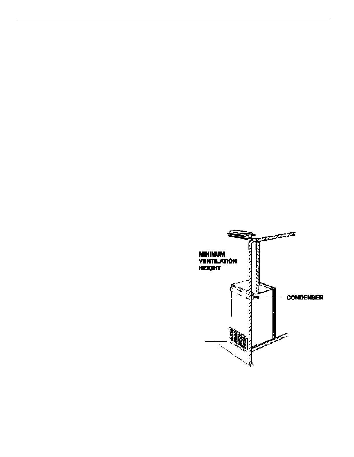
4. METHOD OF INSTALLATION
The method of installation is shown in FIG. 1. It is essential
that all maximum or minimum dimensions are strictly maintained as the performanceof the refrigerator is dependent on
adequate flow of air over the rear of the refrigerator.
NOTE: The upper vent should be
centered over the condenser coil
at the
back
of the refrigerator.
FIG.
1
2. VENTILATION
The installation shall be made in such a manner as to
separatethecombustion system from the living
mobile home or recreational vehicle. Louveropeningsforair
supply or for venting of combustion products shall have a
minimum dimension of not less than
Proper installation requires one fresh air intake and one
upper exhaust vent. The ventilation kits shown in this
instruction manual have been certified for use with the
refrigerator model listed in the Table. For “Certified Vent
System Kits” see Section B. The ventilation kits must be
installed and used without modification. An opening toward
theoutsideatfloor level in the refrigeratorcompartment must
be provided forventilation of heavier-than-air fuel gases. The
lower vent of the recommended kits is provided with proper
size openings. The flow of combustion and ventilation air
must not be obstructed.
1/4
inch.
space of
the
2
Page 3

5.VENTILATION HEIGHTS
Refer to FIG 1., Page 2
Installation with roof Minimum Ventilation
vent and lower side vent heights in:
REFRIGERATOR INCHES MM
RM2652 57-3/4 1465
RM2852 63-3/4 1620
LOWER VENT CUTOUT
13-3/4"
21-9/16"
UPPER VENT CUTOUT
5-1/2"
6.CLEARANCES
Minimum clearances in inches to combustible materials are:
G: Top 0"
K: Side 0"
L: Bottom 0"
M: Rear 0"
N: See NOTE
NOTE: Clearance "M" is between the rearmost part of the
refrigerator and the wall behind the refrigerator.
NOTE: Clearance "N" is the distance between the bottom
of the lower vent to the roof material. For ventilation
height, refer to
Heights
FIG. 2
Section A. Installation, Item 5. Ventilation
. See FIGS. 1 & 2.
NOTE: Wood Strip
MUST be in Place
23-3/4"
NOTE: All cutout dimensions are +/– 1/8".
FIG. 3
Refrigerator Overall Recess Tota l
Model Dimensions Dimensions Ref. Vol.
RM2652 (Inches)
(mm)
RM2852 (Inches)
(mm)
Height Width Depth Height Width Depth
A B C H W D Cu. Ft.
54-9/16 24-11/16 24-7/8 53-3/4 23-11/16 24 6.0
1386 627 632 1365 601 608
60-5/8 24-11/16 24-7/8 59-15/16 23-11/16 24 7.3
1530 627 632 1522 602 610
3
Page 4
7. INSTALLING REFRIGERATOR IN
ENCLOSURE
NOTE: DO NOT install the appliance directly on carpeting.
Carpeting must be removed or protected by a metal or
wood panel beneath the appliance, which extends at least
the full width and depth of the appliance.
Any space between the counter, storage area or ceiling
can trap heat produced at the rear of the refrigerator. Any
space between the top and sides of the refrigerator should
be blocked for maximum refrigerator performance.
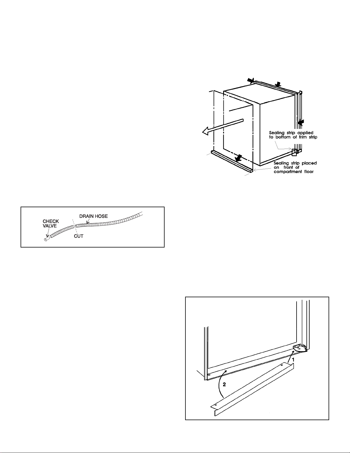
CONDENSATE WATER DRAIN HOSE: A 3/4" hole must
be drilled through the flooring in the opening of the base
plate on the rear of refrigerator (see FIG. 5D). The installer
must make sure that the hose does not kink when run
through the floor. Seal around the hose where it goes
through the hole. If a longer hose is required, follow the
illustration shown below:
OPTION A:
1) Remove black water check valve from hose.
2) Add additional hose
3) Reinstall black water check valve
A wood strip must be in place across the upper opening of
the enclosure. The top frame of the refrigerator will be
anchored to the wood strip with screws. See FIG. 2.
The dimensions shown in FIG. 3 will give you adequate
space for service and proper installation.
NOTE: If the door is hinged and it needs be changed to the
opposite side, it must be done before the refrigerator is
installed in the enclosure. See Step. 13.
FIG. 4
OPTION B:
1) Cut drain hose at location shown below.
2) Install new drain hose between pieces cut.
NOTE: Black water check valve must be reinstalled to
ensure proper refrigerator operation. DO NOT KINK HOSE.
OPTION C:
In vehicles where routing the drain hose through the floor
is not possible, a metal clip is available. The clip is used to
drain water out through the side vent.
Part No. 3106590.007 Clip for plastic side vent (Qty. 50)
Part No. 3106590.015 Clip for plastic side vent (Single)
Part No. 3106559.002 Clip for metal side vent (Qty. 50)
Part No. 3106559.010 Clip for metal side vent (Single)
INSTALLATION: The refrigerator must be installed in a
substantial enclosure and must be level. When installing
the refrigerator in the enclosure, all areas within the recess
in which the refrigerator is installed must be sealed. Make
sure that there is a complete seal between the front frame
of the refrigerator and the top, sides and bottom of the
enclosure. A length of sealing strip is applied to the rear
surface of the front frame for this purpose. Also apply a
sealing strip to the foremost floor of the enclosure and
apply a second sealing strip to the bottom of the trim strip
on the front base as shown in FIG. 4. The sealing should
provide complete isolation of the appliance's combustion
system from the vehicle interior.
NOTE: Be careful not to damage the sealing strip applied
to the floor of the enclosure when the refrigerator is put in
place.
The refrigerator is secured in the enclosure with six screws.
They must be installed in the following order:
a. First: Two screws are installed in front deco-
ration strip and through the front base.
1) The front strip is to be installed after the refrigerator is set into the alcove. The strip is shipped
as a loose part.
2) Install the lower front strip by sliding it under the
bottom hinge plate as shown in FIG. 5. The
hinge plate can be on the right or left side
depending on the door swing.
FIG. 5
4
Page 5
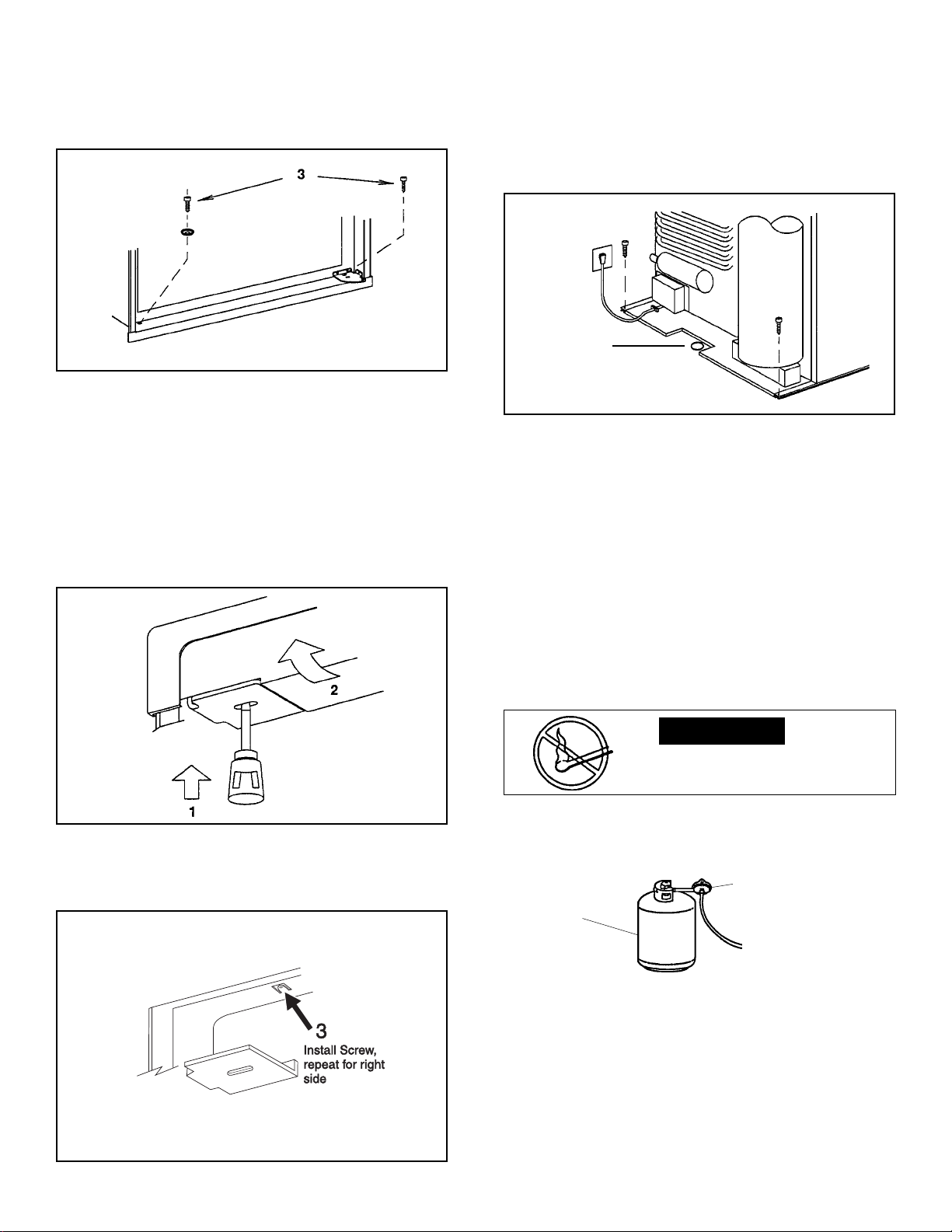
3)When the front strip is in place, install one screw
through the hinge and into the floor. The second
screw is installed with a washer on the opposite
side. (See FIG. 5A)
FIG. 5A
b.Second: Install the two screws in the top
frame.
1)The top decoration panel must be removed
from the refrigerator before the screws can be
installed. Open refrigerator door and gently
push the tabs out of the hole in the hinge with flat
blade screwdriver. See FIG. 5B.
2)Carefully tilt the top decoration panel and lift up
to remove from top frame. See FIG. 5B.
FIG. 5B
4)Replace the top decoration panel. Be careful
not to pinch the wires. Make sure the tabs snap
back into the holes in the hinge plate.
C.Third: Two screws installed as shown in
rear base. See FIG. 5D.
FIG. 5D
Hole for
Drain Water
Hose
Failure to follow the sequence in securing the refrigerator
in the enclosure can cause leakage between the frame and
cabinet.
8.GAS CONNECTION
Hook up to the gas supply line is accomplished at the manual
gas shutoff valve, which is furnished with a 3/8" SAE (UNF
5/8" – 18) male flare connection. All completed connections
should be checked for leaks with a noncorrosive leak
detector. (See FIG. 6 – Gas tubing may have a different
orientation than shown).
3)Install the second two screws in the top frame
as shown in FIG. 5C.
FIG. 5C
! WARNING
DO NOT USE A FLAME
TO CHECK FOR GAS LEAKS.
The gas supply system must incorporate a pressure regulator to maintain a supply pressure of not more than 13-1/2
inches water column (static) no load.
LP GAS
CYLINDER
When testing the gas supply system at test pressures in
excess of 1/2 psig, the refrigerator and its individual shutoff
valve must be disconnected from the gas supply piping
system.
5
PRESSURE
REGULATOR
TO
REFRIGERATOR
Page 6
When testing the gas supply system at pressures less than
or equal to 1/2 psig, the appliance must be isolated from the
gas supply piping by closing its individual manual shutoff
valve.
In case detailed instructions on the installation and connection to the gas supply are required, contact your dealer or
distributor.
9.TESTING LP GAS SAFETY
SHUTOFF
The gas safety shutoff must be tested after the refrigerator
is connected to LP gas supply.
To test the gas safety shutoff, proceed as follows:
A.Start the refrigerator according to the instructions, and
switch to gas mode. See "Section C. Operation Instruc-
tions."
B.Check that the gas flame is lit.
C.Close the manual shutoff valve at the back of the
refrigerator. (See FIG. 6)
D.Wait for one minute. The check indicator lamp (B) should
now be lit and the gas mode indicator lamp should be off.
E.Remove cover (see FIG. 6) and open the manual gas
valve. Apply a noncorrosive commercial bubble solution
to burner jet (see FIG. 6).
switch OFF and back ON. (See "Section C. Operation
Instructions, Item 2. Control Panel"). Normal operation of
the burner should return. Allow the burner to operate for
a minimum of 5 minutes.
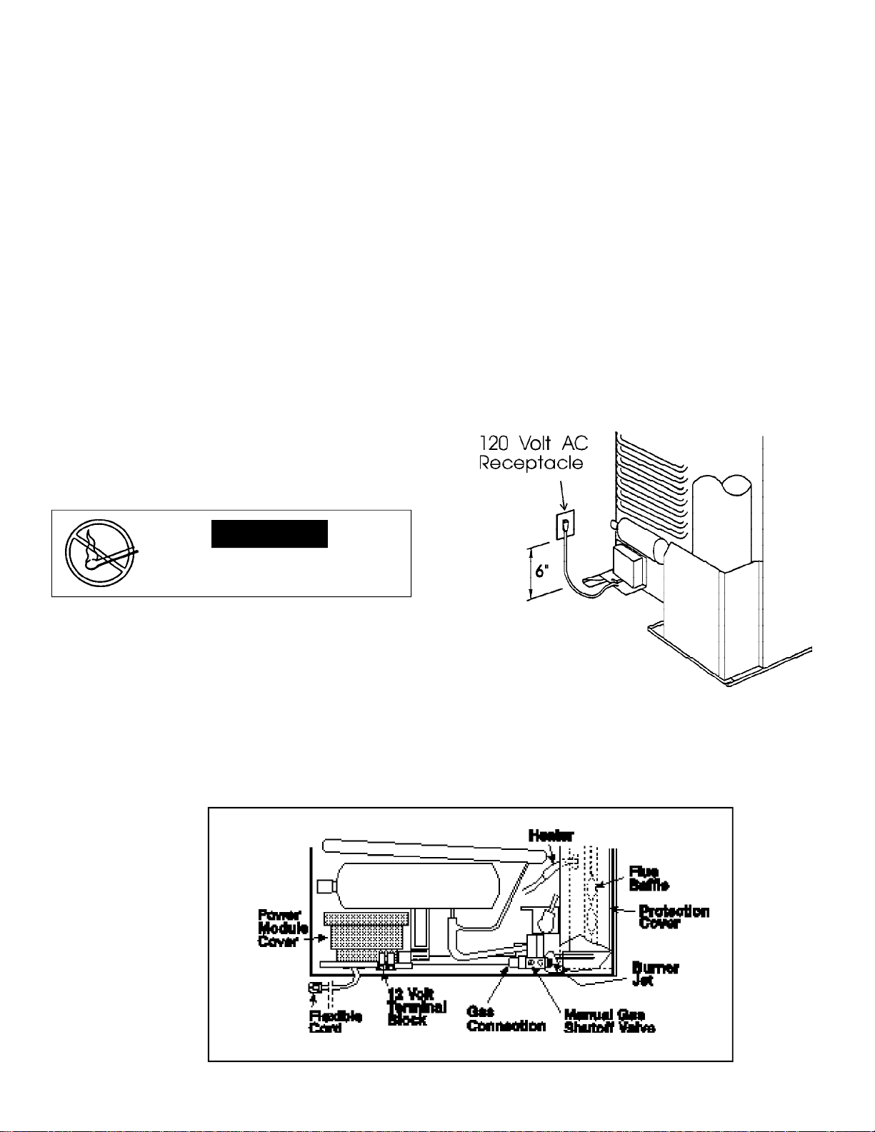
10.120 VOLT AC ELECTRICAL
CONNECTION
The refrigerator is equipped with a three-prong (grounded)
plug for protection against shock hazards, and should be
plugged directly into a properly grounded three-prong receptacle. DO NOT cut or remove the grounding prong from this
plug. The power cord should be routed to avoid direct contact
with the burner cover, flue cover or manual gas shutoff valve
knob. The free length of the cord is two feet and therefore
recommended that the receptacle be located to the left side
of the refrigerator (viewed from the rear) and approximately
six inches from the floor (see FIG. 7). This allows easy
access through the vent door.
! WARNING
DO NOT USE A FLAME
TO CHECK FOR GAS LEAKS.
F.No bubbles should appear at the opening of the burner jet.
The presence of bubbles indicates a defective gas safety
shutoff, and service is required.
G.If no bubbles were present at the burner jet, the gas
safety valve is working properly. Rinse jet thoroughly
with fresh water before proceeding. Be careful not to
damage burner jet. Replace cover and turn the main
FIG. 6
FIG. 7
6
Page 7
11. 12 VOLT DC CONNECTION
This refrigerator model is not designed for 12 volt DC
operation of the cooling system; however, 12 volt DC must
be supplied to the refrigerator to operate the controls. Use a
minimum of a 14 gauge wire between the battery and
refrigerator to supply the control voltage. The connection is
made to the positive (+) and negative (–) terminals of the
terminal block on back of refrigerator. (See FIG. 6) The 12
volt DC supply circuit must be fused, and the maximum
fuse size is 5 amps.
DO NOT use the chassis or vehicle frame as one of the
conductors. Connect two wires at the refrigerator and route
to the DC supply.
Clean Direct Current (DC) power is mandatory for hightech circuits to operate as designed. The sources for DC
power are a battery and a converter.
A battery will provide straight line DC power, but extended operation will require recharging of the battery
by the converter or the alternator.
The converter and alternator produces DC power by a
series of diodes that rectify alternating current to DC. A
battery or capacitors can be used to clean up the AC
ripple that is present after AC voltage has been rectified.
FIG. 8
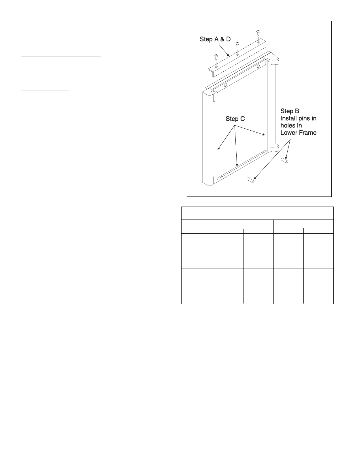
12.INSTRUCTION FOR INSTALLING
DOOR PANEL
The refrigerator is normally delivered without the door panels. Before starting the mounting work, check that the panel
dimensions are in compliance with those given in the Table
on this page and the instructions are read thoroughly. When
mounting the panel, proceed as follows. (See FIG. 8)
A. Remove the trim strip from the door by taking out the 3
screws. See FIG. 8.
B. Locate the 2 pins in the end frame of the door. If they
are in the top frame, relocate the pins into the holes in
the bottom door frame to support the panel. See FIG.
8.
C. Slide panel into grooves on vertical edges of the door
until it slips into the groove on the opposite end of door.
D. Replace trim strip and screws.
13. CHANGING DOOR SWING TO
OPPOSITE SIDE
PANEL DIMENSIONS
MAX. THICKNESS 5/32" (4 mm)
Refr. Models HEIGHT WIDTH
TYPE MAX. MIN. MAX. MIN.
RM2652
upper mm 403 401 527 524
inch 15-7/8 15-3/4 20-3/4 20-5/8
lower mm 827 825 527 524
inch 32-11/16 32-5/8 20-3/4 20-5/8
RM2852
upper mm 403 401 527 524
inch 15-7/8 15-3/4 20-3/4 20-5/8
lower mm 983 981 527 524
inch 38-11/16 38-5/8 20-3/4 20-5/8
The refrigerator is equipped with convertible doors. To
change the door swing, consult the parts manual for
the Conversion Kit Part Number. For further information, please contact the Dometic Corporation listed on
the front page.
7
Page 8
SECTION B. CERTIFIED VENT SYSTEM KITS
REFRIGERATOR KIT
MODEL NO. COMPONENTS PART NO.
RM2652 OPTION #1 ROOF BASE 3103633.XXX *
RM2852 ROOF COVER 3103634.XXX *
LOWER SIDE VENT 3102277.XXX *
OPTION #3–A
POWER VENTILATOR POWER VENT ASM. 3104131.002 **
(Island/through ROOF BASE 3103633.XXX *
floor) ROOF COVER 3103634.XXX *
* Fill in "XXX" with color code numbers. For color codes, contact your supplier.
** Alternate instructions forwarded with the Ventilator Kit.
SECTION C. OPERATING INSTRUCTIONS
Most LP gas appliances used in recreational vehicles are vented to the outside of the vehicle. When parked
close to a gasoline pump, it is possible that the gasoline fumes could enter this type of appliance and
ignite from the burner flame, CAUSING A FIRE OR AN EXPLOSION.
FOR YOUR SAFETY, when refueling, shut off all LP gas appliances which are vented to the outside.
1. IMPORTANCE OF LEVELING A REFRIGERATOR
In an absorption refrigerator system, ammonia is liquefied in
the finned condenser coil at the top of the refrigerator. The
liquid ammonia then flows into the evaporator (inside the
freezer section) and is exposed to a circulating flow of
hydrogen gas, which causes the ammonia to evaporate,
creating a cold condition in the freezer.
The tubing in the evaporator section is specifically sloped to
provide a continuous movement of liquid ammonia downward by gravity through this section. If the refrigerator is
operated when it is not level and the vehicle is not moving,
liquid ammonia will accumulate in sections of the evaporator
tubing. This will slow the circulation of hydrogen and ammonia gas, or in severe cases, completely block it, resulting in
a loss of cooling.
Any time the vehicle is parked for several hours with the
refrigerator operating, the vehicle should be leveled to
prevent this loss of cooling. The vehicle needs to be leveled
only so it is comfortable to live in (no noticeable sloping of
floors or walls).
When the vehicle is moving, the leveling is not critical as the
rolling and pitching motion of the vehicle will pass to either
side of level, keeping the liquid ammonia from accumulating
in the evaporator tubing.
8
Page 9
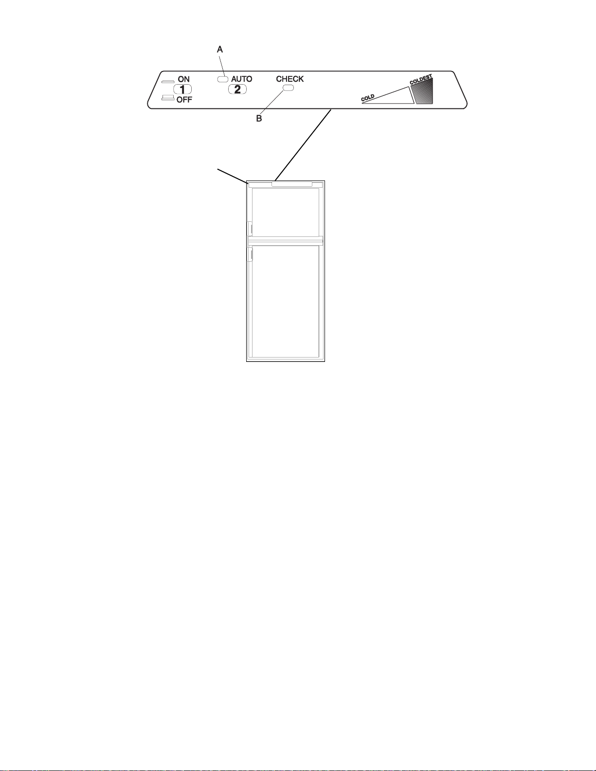
2. CONTROL PANEL
FIG. 10
2-WAY DISPLAY PANEL
C
LEGEND 2-WAY MODEL
1. Main Power Button ON/OFF
2. AUTO/MANUAL Mode Selector Button
A. AUTO Mode indicator lamp
B. CHECK indicator lamp (Gas Mode Only)
C. Climate control switch
3. START-UP INSTRUCTIONS
Before starting the refrigerator, check that all the manual gas
valves are in the ON position. DO NOT forget the manual
shutoff valve on the rear of the refrigerator. See FIG. 6.
This refrigerator is equipped with a control system, which
can automatically select the most suitable energy source
which is available, either 120 Volt AC or LP gas operation.
The refrigerator can be operated in either the AUTO mode
(thermostat factory preset below the safe food storage
temperature) or MANUAL mode (continuous operation - no
thermostat control).
NOTE: Under certain cool weather conditions, the food in the
lower portion of the fresh food compartment may freeze if
operated for an extended period of time on the MANUAL
mode.
A. A 12 volt DC supply must be available for the electronic
control to function. The refrigerator will work down to 9.6
volt DC.
B. Press the main power ON/OFF button (1) to the
DOWN position.
B. In AUTO mode operation, the temperature is controlled
by a single temperature setting, on the energy source
selected by the control system. (See Auto Mode)
C. In MANUAL mode operation, the refrigerator will run
continuously on the energy source selected by the
control system. (See Manual Mode)
NOTE: The food in the lower compartment may be frozen if
the refrigerator is left on MANUAL mode.
D. TO SHUT OFF THE REFRIGERATOR
The refrigerator may be shut off while in any mode of
operation by pressing the main power ON/OFF button to
the UP (OFF) position. This shuts off all DC power to the
refrigerator, including the interior light.
4. DESCRIPTION OF OPERATING
MODES
A. AUTO MODE
Press the AUTO/MANUAL mode selector button (2) to the
DOWN position. The AUTO mode indicator lamp (A) will
illuminate.
When operating in the AUTO mode, the AUTO mode
indicator lamp (A) will illuminate. The control system will
automatically select between AC and GAS operation with
AC having priority over GAS. If the control system is
operating on AC energy and it then becomes unavailable, the
system will automatically switch to GAS. As soon as AC
becomes available again the control will switch back to AC
operation.
9
Page 10
If 120 volts AC is not available, the control system will
automatically switch to GAS operation. Within 45 seconds
the burner should be ignited and operating normally. If
unsuccessful, the CHECK indicator lamp (B) will illuminate.
To restart an ignition attempt with the CHECK lamp
illuminated or to clear (turn off) the CHECK lamp, press the
main power ON/OFF button to the OFF and the ON
position. The control system will attempt a new 45 second
ignition sequence.
On the initial refrigerator start-up on gas (120 volts AC is
not available), it may take longer than 45 seconds to allow
air to be purged from the gas line. If the refrigerator has not
been used for a long time or the LP tanks have just been
refilled, air may be trapped in the supply lines. To purge the
air from the lines may require resetting the main power ON/
OFF button (1) three of four times. If repeated attempts fail
to start the LP gas operation, check to make sure that the
LP gas supply tanks are not empty and all manual shutoff
valves in the lines are open. If the problem is still not
corrected, contact a service center for assistance.
NOTE: DO NOT continue to reset GAS operation if the
CHECK indicator lamp continues to be illuminated after 3
or 4 tries.
If 120 volts AC becomes available while the CHECK
indicator lamp is on, the control system will switch to 120
volt AC operation. The CHECK lamp will not turn off until
the main power ON/OFF button is pressed to the OFF then
ON position.
In AUTO mode operation, the temperature is controlled by
a single temperature setting.
B.FROZEN FOOD STORAGE
COMPARTMENT
Quick frozen soft fruits and ice cream should be placed in the
coldest part of the compartment which is on or just below the
freezer shelf. Frozen vegetables, may be stored in any part
of the compartment.
This compartment is not designed for deep or quick freezing
of food. Meat or fish, whether raw or prepared, can be stored
in the frozen food storage compartment provided they are
precooled first in the refrigerator. They
can be stored about three times longer in the frozen food
compartment as compared to the fresh food compartment.
To prevent food from drying out, keep it in covered dishes,
containers, plastic bags or wrapped in aluminum foil.
C. ICE MAKING
Ice cubes can be made in the ice tray placed in the freezer
compartment. The tray should be filled with water to within
1/4" (5mm) from the top. For faster ice making, the tray
should be placed in direct contact with the freezer shelf.
To release the ice cubes, seize the tray with both hands and
twist the tray. Cubes not required should be replaced in the
tray. Refill the tray with water and replace the tray on the
freezer shelf.
Ice will be made more rapidly if the control panel is set in the
MANUAL position. It is a good idea to do this a few hours
before the anticipated need for ice, but be sure to set the
control back to AUTO setting when the ice is formed. Food
in the lower compartment may be frozen if the setting is left
in the MANUAL position.
B.MANUAL MODE
When operating in the MANUAL mode, the AUTO mode
indicator lamp (A) will be off, and the refrigerator will run
continuously on the energy source selected by the control
system.
5.HOW TO USE THE REFRIGERATOR
A.FOOD STORAGE COMPARTMENT
The food storage compartment is completely closed and
unventilated, which is necessary to maintain the required low
temperature for food storage. Consequently, foods having a
strong odor or those that absorb odors easily should be
covered. Vegetables, salads, etc. should be covered to
retain their crispness. The coldest positions in the refrigerator are under the cooling fins and at the bottom of the
refrigerator. The warmer areas are on the upper door shelves.
This should be considered when placing different types of
food in the refrigerator.
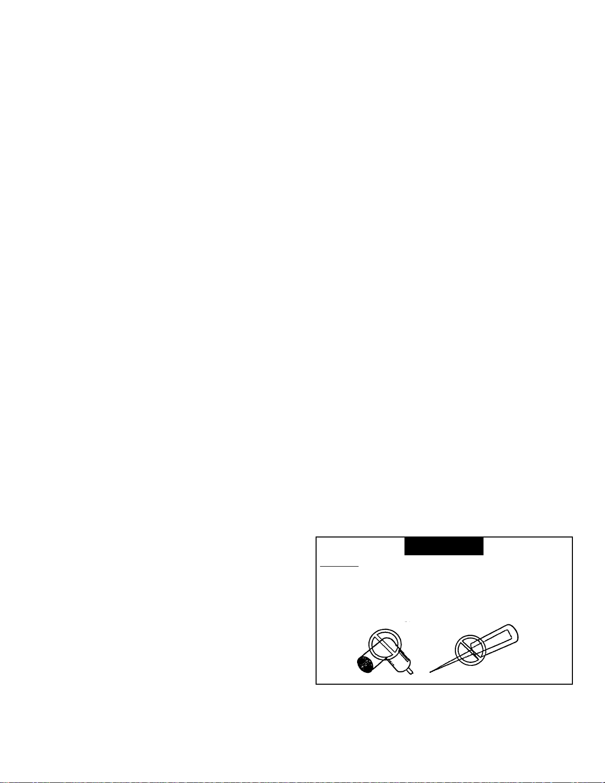
D. DEFROSTING
Shut off the refrigerator by pressing the main power ON/OFF
button to the UP (OFF) position. Empty the refrigerator,
leaving the drip tray under the finned evaporator, and the
cabinet and freezer doors open. Defrosting time can be
reduced by filling the ice tray with hot water and placing it on
the freezer shelf.
! CAUTION
DO NOT use a hot air blower. Permanent damage could
result from warping the metal or plastic parts. DO NOT use
a knife or an ice pick, or other sharp tools to remove frost
from the freezer shelf. They can create a leak in the ammonia
system.
10
Page 11
When all frost is melted, dry the interior of the refrigerator with
a clean cloth. Replace all food and turn the refrigerator back
on.
E. CLEANING
Cleaning the refrigerator is usually done after it is defrosted
or put into storage. To clean the interior liner of the refrigerator, use lukewarm weak soda solution. Use only warm water
to clean the finned evaporator, gaskets, ice trays and
shelves. NEVER use strong chemicals or abrasives to clean
these parts as the protective surfaces will be damaged. It is
important to always keep the refrigerator clean.
F.SHUT-OFF (STORAGE PROCEDURE)
Shut off the refrigerator by pressing the main power ON/OFF
button to the UP (OFF) position. (See FIG. 10)
If the refrigerator will not be in operation for a period of weeks,
it should be emptied, defrosted, cleaned and the doors left
ajar. The ice tray should also be dried and kept outside the
cabinet.
! WARNING
DO NOT store explosive substances in the refrigerator,
such as gasoline and other flammable vapors or liquids.
G. CLIMATE CONTROL
During the summer months of high temperatures and humidity, the metal frame between the freezer and fresh food
compartments may have water droplets forming. The number of water droplets will increase if the vehicle isn't air
conditioned during these months.
This refrigerator comes standard with a 12 volt (DC) climate
control that will evaporate the water droplets when they form.
To have the climate control on, you position the switch ("C",
Figure 10) located beneath the top decorative strip that
houses the control panel to ON. The climate control can be
left on continuously or only used when temperatures require
it.
! CAUTION
THE CLIMATE CONTROL WILL DRAW 12 VOLT DC
POWER CONTINUOUSLY WHEN IN THE "ON" POSITION. IT SHOULD BE TURNED "OFF" WHEN A CHARGING SOURCE IS NOT AVAILABLE. IT WILL QUICKLY
DRAIN THE CHARGE FROM A BATTERY.
(Section D. Maintenance & Service, continued on
next page)
11
Page 12
SECTION D. MAINTENANCE & SERVICE
MANUAL SHUTOFF VALVE
E
JET
Tips for the Service Technician
The user should be aware of service that must be done on a regular schedule to keep the refrigerator operating properly.
The service should only be performed by a qualified technician who is familiar with LP gas systems and refrigerators.
1. REFRIGERATOR REMOVAL
Before working on the refrigerator, make sure the AC voltage
and DC voltage leads are disconnected. Shut off the gas
supply at the LP tank. Disconnect the gas supply line. Cap
the gas supply line, loosen the screws anchoring the
refrigerator to the enclosure and slide the refrigerator out of
the compartment.
Replacement is the reverse of removal. Check all connections for gas leaks. Refer to
Installation Instructions
.
Section A, Item 1 to 12 of
2. PERIODIC MAINTENANCE
To keep your Dometic refrigerator operating efficiently and
safely, periodic inspection and cleaning of several components once or twice a year is recommended.
A. It is important to keep the area at the back of the
refrigerator clean. Check the lower vent, upper vent and
area between these openings for any obstructions such
GAS EQUIPMENT ASSEMBLY
as bird/insect nests, spider webs, etc. Clean the coils on
the back of the refrigerator. Use a soft bristled brush to
dust off the coils.
It is important to keep the refrigerator vent area free from
combustible material, gasoline and other flammable
vapors or liquids.
NOTE: The following maintenance is required once or twice
a year, but should only be done by a qualified serviceman
who is familiar with LP gas systems and refrigerators.
B. Check all connections in the LP gas system (at the back
of the refrigerator) for gas leaks. The LP gas supply must
be turned on. Apply a noncorrosive bubble solution to all
LP gas connections. The appearance of bubbles indicates a leak and should be repaired immediately by a
QUALIFIED SERVICEMAN WHO IS FAMILIAR WITH
LP GAS SYSTEMS AND REFRIGERATORS.
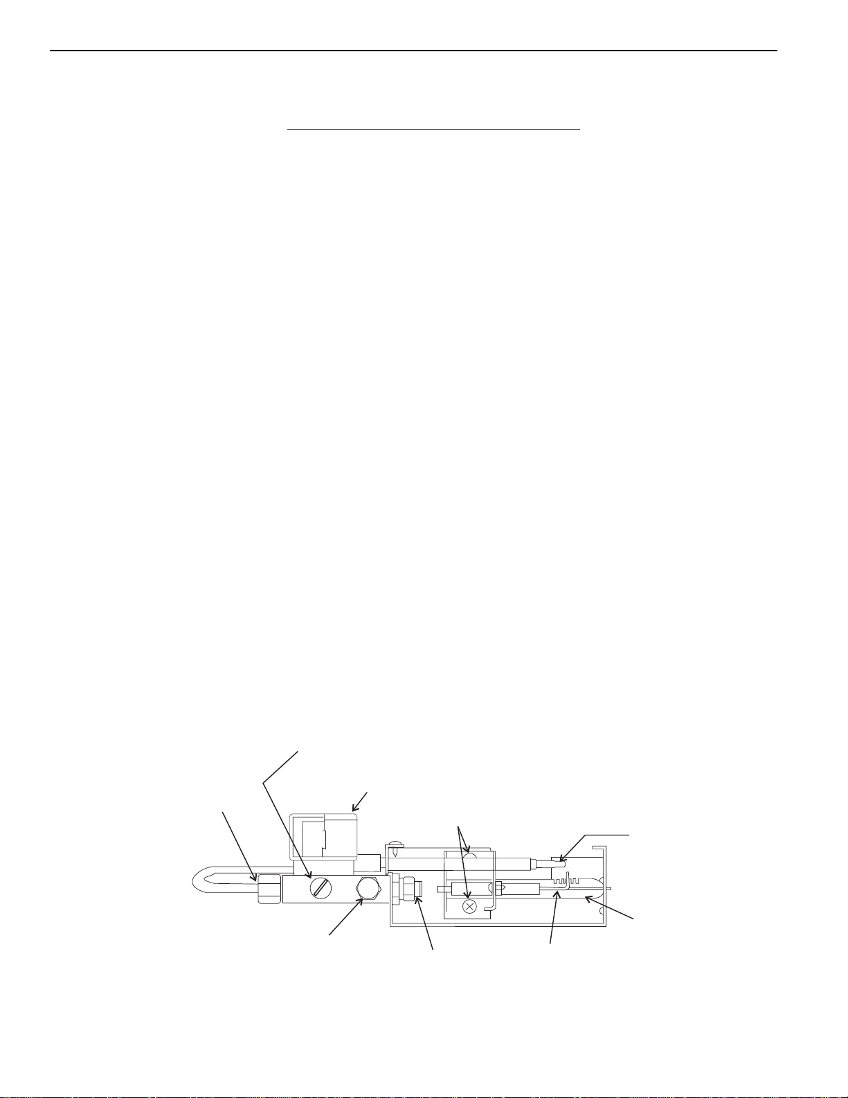
FIG. 12
Use a quarter dollar or a slotted screwdriver
to change position
INLET FITTING
PRESSURE TEST
PORT
SOLENOID VALVE
BURNER MOUNTING SCREWS
BURNER
SPARK
ELECTRODE
THERMOCO UPL
BURNER
TUBE
12
Page 13
! ! WARNING
DO NOT USE A FLAME
TO CHECK FOR GAS LEAKS.
C.Check the control system by connecting/disconnecting
120 volt AC power, start/stop the engine, etc. Compare
the operation with the operation described in
Operation Instructions
D.The LP gas pressure should be checked and the main
regulator readjusted if pressure is incorrect. The correct
operating pressure is 11 inches of water column. The
correct place to take the LP gas pressure is at the test
port just ahead of the burner jet. (See FIG. 12).
E.Inspect the flue baffle. It should be reasonably clean and
free of soot. Heavy soot formation indicates improper
functioning of the burner. The flue and burner both require
cleaning in the following manner:
1)Unplug the refrigerator power cord from the 120 volt
AC outlet (see FIG. 6).
2)Disconnect or shut off the 12 volt power to the
refrigerator.
3)Turn manual shutoff valve to OFF. (See FIG. 6 & 12).
4)Remove cover from the burner housing. (See FIG . 6).
5)Disconnect the wire from the high voltage electrode.
6)Remove the burner mounting screws and remove the
burner assembly.
7)Remove the flue cap from top of flue tube and lift out
the wire and spiral baffle. Clean the flue from the top
using a flue brush. Blowing compressed air into the
flue will not properly clean soot and scale out of the
flue tube. Replace spiral baffle and flue cap.
8)Clean burner tube with a brush. Blow out burner with
compressed air.
9)Before removing burner jet, clean burner area of soot
and scale that fell out of flue tube. Remove the burner
jet. Soak the jet in wood alcohol and blow it out with
compressed air. Reinstall and tighten burner jet.
DO NOT use a wire or pin when cleaning the burner jet
as damage can occur to the precision opening. This can
cause damage to the refrigerator or create a fire hazard.
10)Reinstall burner, being careful that the end of the
burner fits into the slot on the burner bracket. Check
to make sure slots are centered under the flue tube
and the thermocouple is positioned properly (tip of
thermocouple extends over two slots of burner).
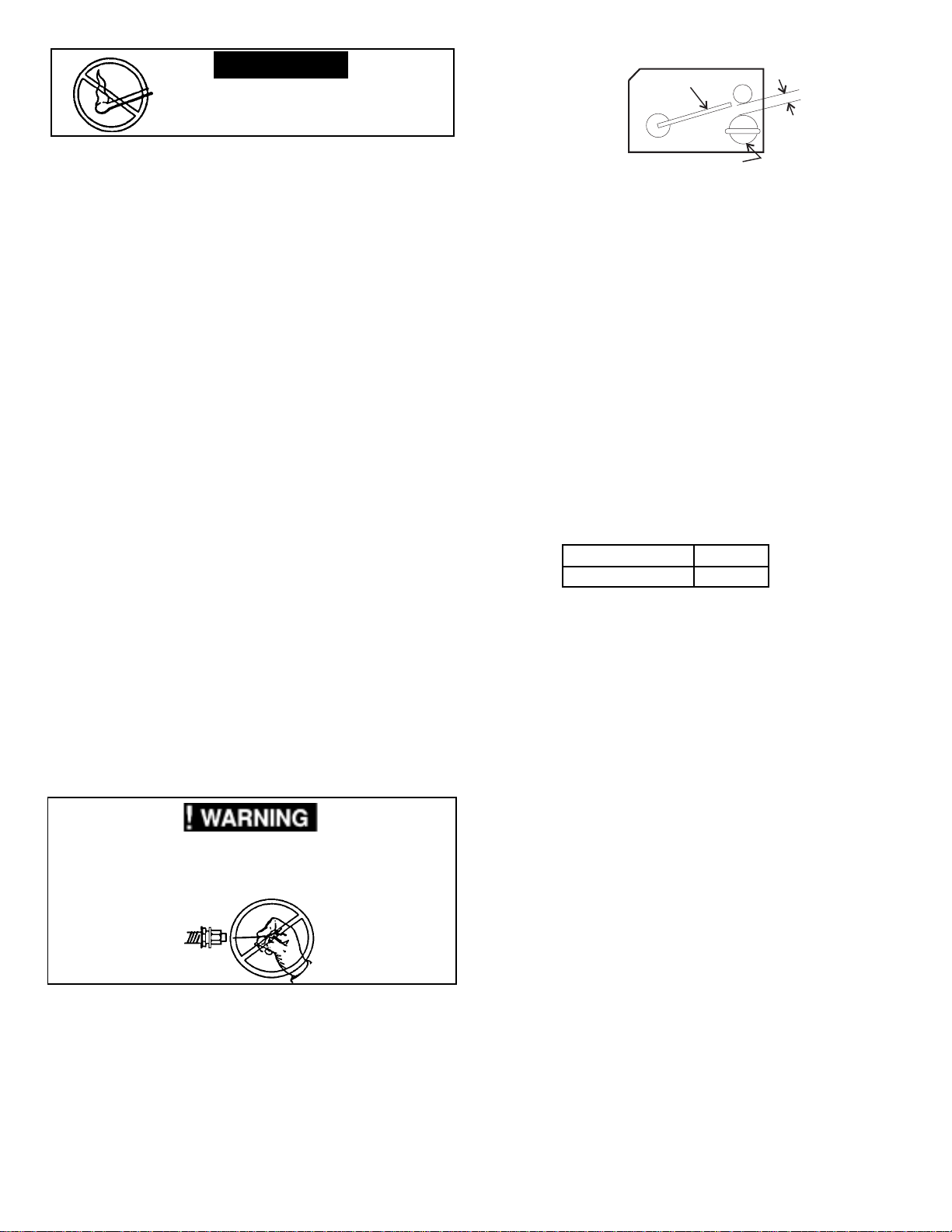
11)Be sure to reconnect the wire to high voltage elec-
trode. Check the electrode for proper location and
gap. (See FIG. 13).
.
Section C.
FIG. 13
12)Turn on manual gas shutoff valve and check all
fittings for leaks.
13)Connect 120 volt power cord to the outlet and
reconnect or turn on the 12 volt DC power.
14)Check LP gas safety shutoff. See
lation, Item 9. Testing LP Gas Safety Shutoff
F.FUSES
The 2-way models are equipped with 2 fuses, one for the
refrigerator control system and one for the AC cartridge
heater (see Table below). To replace fuse(s) proceed as
follows:
1.Disconnect the wall plug, and the 12 volt wires.
2.Remove the power module cover. See FIG. 6.
3.Snap the fuse out of the fuse holder.
4.Fit a new fuse in to the fuse holder.
5.Replace the power module cover.
Control System 3-amp
AC Heater 5-amp
ELECTRODE
1/8" TO 3/16"
(3-5 mm)
BURNER TUBE
Section A. Instal-
.
3.TROUBLESHOOTING
Refrigerator Does Not Cool Properly
A.Burner jet clogged.
Clean. See
Periodic Maintenance, Paragraph E. Item 1–14.
B.Check level of refrigerator.
C.Venting problem.
Restriction in air flow across cooling unit.
D.Heavy frost buildup on evaporator fins.
Defrost.
E.Flue baffle not inserted properly in flue tube.
F.Improperly set thermostat.
See
Section C. Operating Instructions, Item 3.
Paragraph F.
G.Burner dirty.
Clean. See Section D. Maintenance & Service, Item 1.
Periodic Maintenance, Paragraph E.8.
H.LP gas pressure low at burner.
Set main regulator so pressure does not drop below 11
inches water column at pressure tap.
I.Burner not located properly under flue tube.
Relocate.
J.Burner damaged.
Replace.
K.Odors and fumes.
1.Dislocated burner.
2.Damaged burner
3.Dirty flue tube.
Section D. Maintenance & Service, Item 1.
13
Page 14

L. FUSES
1) Refrigerator AC supply
2) Refrigerator DC supply
3) Refrigerator Control System
See
Section D. Maintenance &Service
Paragraph F.
, Item 2,
Contact an authorized service center for parts
and repairs as needed.
14
 Loading...