

Page 1
Service Instructions
RH423LDA RH423LDAG
RH439LDA RH439LDAG
RH449LD
RH439D RH449D
Freestanding and built-in absorption refrigerators
1
Page 2

Table of Contents:
1. The appliance ............................................................................... 3
1.1. Description .................................................................................... 3
1.2. Warning ........................................................................................ 3
1.3. Spare parts, electrical connection diagram ................................... 3
2. Assembly and repairs ................................................................... 4
2.1. Tools ............................................................................................. 4
2.2. Cabinet, door ................................................................................ 5
2.2.1. Reversing the door hang .............................................................. 5
2.2.2. Changing feet ............................................................................... 7
2.2.2.1. Front feet .................................................................................... 7
2.2.2.2. Rear feet ..................................................................................... 7
2.2.3. Replacing the flange ................................................................... 8
2.2.4. Replacing the door lock .............................................................. 9
2.2.5 Replacing the door plate ............................................................. 10
2.3. Electrical equipment ................................................................... 12
2.3.1. Operation .................................................................................... 12
2.3.1.1. Description ................................................................................. 12
2.3.1.2. Self-test ...................................................................................... 12
2.3.1.3. Defrost ........................................................................................ 12
2.3.1.4. Checking the cooling unit (CUC) ................................................ 13
2.3.1.5. Checking the Automatic Door Control (optional) function ........... 13
2.3.1.6. Temperature control ................................................................... 13
2.3.2. Assembly .................................................................................... 14
2.3.2.1. Replacing parts under the light cover ......................................... 14
2.3.2.1.1. Replacing the assembled optical sensor .................................... 15
2.3.2.2. Checking and replacing parts connected to
the Fuzzy controller .................................................................... 16
2.3.2.2.1. Replacing the evaporator sensor ................................................ 16
2.3.2.2.2. Replacing the temperature sensor ............................................. 18
2.3.2.2.3. Replacing the heating cartridge .................................................. 19
2.3.2.2.4. Replacing the Automatic Door Control LED ............................... 22
2.4. The cooling unit .......................................................................... 23
2.4.1. Replacing the cooling unit .......................................................... 23
2.5. Information .................................................................................. 24
2
Page 3
1. The appliance
1.1. Description
The appliance is a fluid absorption system freestanding or built-in refrigerator, with a
capacity of 23, 24.5 or 30 liters.
The internal container may be set to two different temperatures (+3°C and +5°C)
between environmental temperatures +16°C and +32°C in the case of the
refrigerators fitted with a Fuzzy III motherboard and a four-button remote control.
Appliances fitted with a so-called reduced-capacity motherboard do not have an
interior temperature control feature.
The appliance is furnished with an integrated electronic control, including the interior
temperature control, the cooling unit control, automatic door control, automatic
defrost and light control. Appliances without lighting are not furnished with the
automatic door control function.
1.2. Warning
- Do not perform any repairs or cleaning on the device when the power plug
is connected to the wall socket!
- The appliance is designed to be operated by adults!
- Always operate the appliance in accordance with the operating manual!
- Any repairs that involve the disassembly of electrical parts should only be
performed by an authorized service person!
- Certain parts of the cooling unit remain hot after switching off for an
extended period of time. Be careful when repairing these parts!
- After repairs involving the disassembly of the electrical circuit or replacing
the cooling unit, make sure to execute an electrical insulation resistance
test! (see 2.3.2.2.)
- Only appliances with the proper qualifications should be connected to the
electrical supply!
- It is recommended to use safety gloves in operations involving injury to the
hand!
- In order to avoid damage to the appliance, during repairs the cabinet
should be placed on a soft underlay (felt, foam).
1.3. Spare parts, electrical connection diagram
Spare parts lists and electrical connection diagrams are listed by Product number at
http://www.electrolux-ti.com.
Warning!
Parts in need of replacement during repairs may only be replaced by parts identical
to the original, chosen from the spare parts list! Using parts not originally
manufactured by DOMETIC shall result in the loss of guarantee.
3
Page 4
2. Assembly and repairs
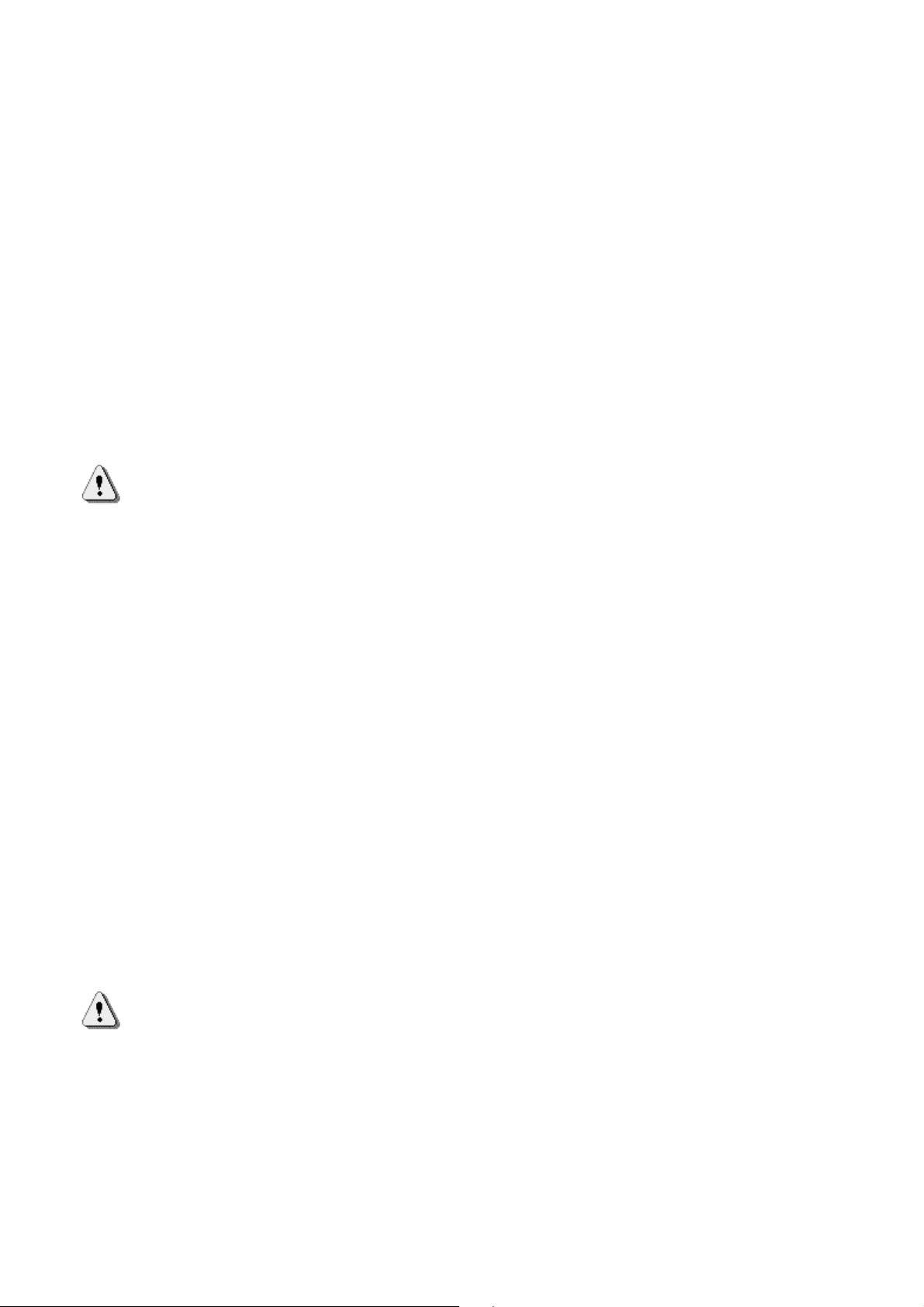
2.1. Tools
Figure 1
Recommended tools:
- combination pliers size 160, 2 pieces
- magnetic screwdriver handgrip
- screwdriver bit marked Pz 1
- screwdriver bit marked Pz 2
- crosshead screwdriver marked Ph 1
- flat screwdriver 120 * 5
- flat screwdriver 100 * 4
- spanner size 14
- testing apparatus for 1000 V electrical insulation resistance
- electrical continuity tester, or resistance measuring (universal) apparatus
4
Page 5
2.2. Cabinet, door
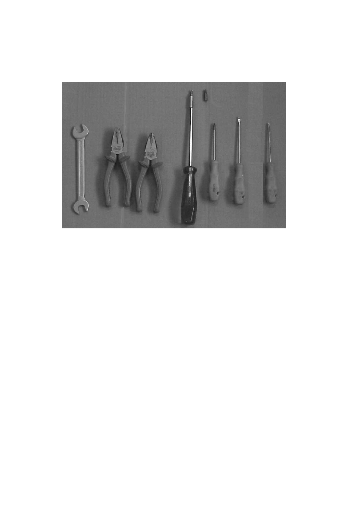
2.2.1. Reversing the door hang
When refitting, take care not to break the lower hinge bolt!
- Remove the screws of the upper door hinge (Figure 2)
- Remove the screws of the upper door hinge cover cap (Figure 3)
Figure 2 Figure 3
- Open the door, pull out the upper door hinge by tilting the door Figure 4)
Figure 4 Figure 5
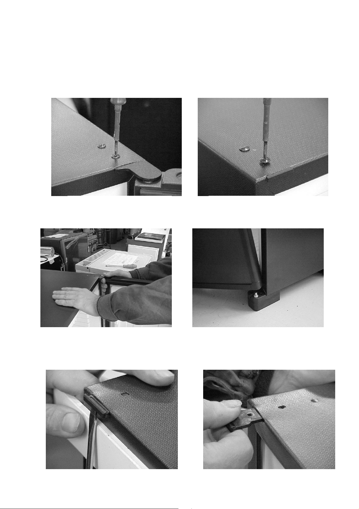
- Put aside the door hinge, unhook door from lower door hinge (Figure 5)
- Remove lower hinge cover cap. Use a flat screwdriver. (Figure 6, 7)
5
Figure 7 Figure 6
Page 6
- Relocate door fulcrum bolt along with spacer ring to left fastening foot (Figure 8)
- Place door on fulcrum bolt (Figure 9)
Figure 8 Figure 9
- Place hinge which comes with the refrigerator into upper left door hinge hole on
door, restore plastic cover, and fasten with 2 screws (Figure 10, 11)
Figure 11 Figure 10
- Restore door hinge cover cap to upper right aperture, then fasten with screw
(Figure 12, 13)
Figure 13 Figure 12
- Make sure that the door can be opened smoothly and that it seals properly.
6
Page 7
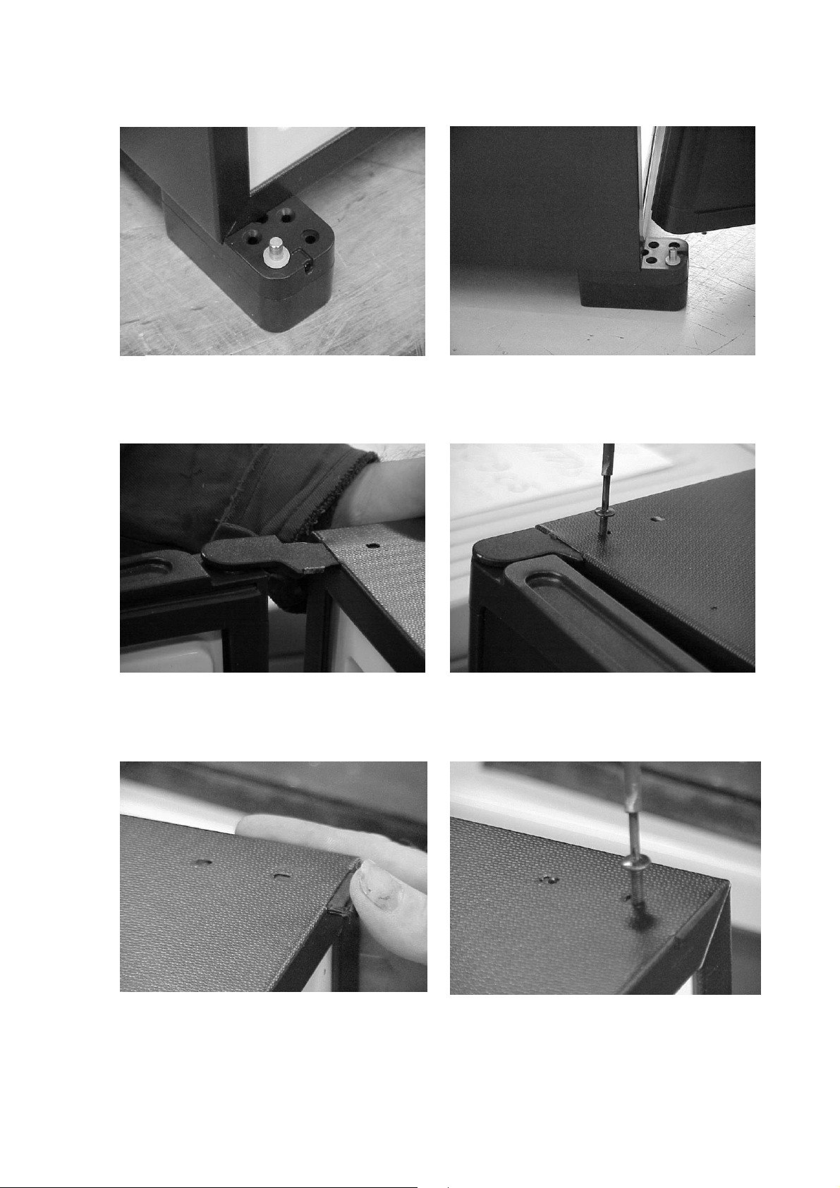
2.2.2. Changing feet
2.2.2.1. Front feet
- Remove foot extension pieces by removing each screw (Figure14)
- Remove fastening feet by screwing each lot of 3 screws (Figure 15)
Figure 14 Figure 15
There are some appliances that are fitted with only fastening feet. The size of such
foot at the back is naturally smaller.
- Remove cables of red-dot from the fastening feet, where applicable.(Figure 16)
Figure 16
2.2.2.2. Rear feet
- Remove rear feet by removing each lot of 2 screws (Figure 17)
- In the case of small feet, remove the rear feet by removing each screw (Figure
18)
Figure 17
7
Figure 18
Page 8
2.2.3. Replacing the cowl
- Turn the cabinet on its door, on an appropriate protective underlay. (Figure 19)
- Remove 2 lower screws fastening the cowl (Figure 20, 21), while the rest of the
screws need only loosening, in order that the cowl can be slid from under the
screw. (Figure 22)
Figure 19 Figure 20
Figure 21 Figure 22
- Remove cowl, then restore the replacement part by sliding it under the screws.
(Figure 23)
Figure 23
- Tighten and restore screws. During tightening check that the cowl and the skirt
are level. If necessary, correct.
8
Page 9

2.2.4. Replacing the door lock
- Open the door.
- Remove rosette with the help of 2 flat screwdrivers. (Figure 24)
Figure 24 Figure 25
- Remove lock cover. With the bolt contracted, pull the rim of the lock cover
onto the bolt with the help of a flat screwdriver, so that it will not spring
back. (Figure 25)
- Remove lock cover with the help of 2 flat screwdrivers. (Figure 26)
- Remove screws from lock. (Figure 27)
Figure 26
Figure 27
- Remove the lock. (Figure 28)
Figure 28
9
Page 10

- Reassembly is performed in a reverse order.
- The rosette and the lock cover should be restored by applying slight
pressure. When restoring the lock cover, the bolt should be contracted.
2.2.5. Replacing the door panel
- Replacement of the door panel must be performed when the door and lock
are disassembled (see sections 2. 2. 1. and 2. 2. 4).
- Remove door shelves. Removing these may be performed by lifting the
shelves. (Figure 29, 30)
Figure 29 Figure 30
- Place the door – door insert facing downwards – on a protective underlay.
- Remove fastening screws from the frame edge. (Figure 31)
- Remove the frame edge from its seating. (Figure 32)
-
Figure 31
Figure 32
10
Page 11

Remove door panel. (Figure 33)
- Place the new door panel in the grooves in the door. Push the panel to an
extent that the holes of the cylinder lock on the panel and the door are
concentric. (Figure 34)
Figure 33 Figure 34
- Insert frame edge, fasten with screws.
- Reassemble lock (see 2. 2. 4)
- Reassemble door (see 2. 2. 1)
11
Page 12

2.3. Electrical equipment
Number of blinks
Error status
2.3.1. Operation
2.3.1.1. Description
The appliance is furnished with integrated electronic control (Fuzzy Logic III).
Electronics include interior temperature control, cooling unit control, automatic
door control, automatic defrost as well as light control. The lighting unit
consists of 2 LED light sources, which, along with providing lighting of the
interior, also indicates the result of the self-test executed by the electronics
when voltage is applied to the appliance, but only when the door is open.
Appliances not fitted with light and those fitted with a reduced-capacity
motherboard do not indicate the result of the
self-test: these appliances signal
error a few hours after switching on, indicated by the shutdown or noninitiation of the cooling unit.
Lighting and door detection is controlled by an infrared sensor operated by the
door. Automatic door control cannot be provided for appliances without
lighting!
Temperature control of the internal container may not be performed manually.
2.3.1.2. Self-test
The built-in electronics execute a self-test when voltage is applied to the
appliance.
The system checks the condition of peripheral devices. The result is indicated
by the variation in the blinking of LEDs (0.5 Hz). Evaluation results are
contained in the following table:
N=0 General error
N=1 Everything in order – control knob is not detected
N=2 Everything in order – control knob is not detected
N=3 NTC detection error (interior sensor)
N=4 NTC detection error (evaporator sensor)
N=5 NTC detection error (interior and evaporator sensor)
After five blinks, the LEDs continue blinking at a higher frequency.
If the electronics do not indicate a failure (two blinks), then after two seconds it
applies voltage to the heating cartridge and normal controlled mode can start.
Appliances fitted with a reduced-capacity motherboard do not indicate the
result of the self-test!
2. 3. 1. 3. Defrost
Defrost is performed automatically by the control mechanism as follows:
- It switches off after 39 hours from first initiation, defrosts for 2 hours, then
switches back on.
- After this, there is a 2-hour defrost period in every cycle after 22 hours of
operation.
12
Page 13

2. 3. 1. 4. Checking the cooling unit (CUC)
The evaporator sensor checks the appropriate operation of the appliance after
every defrost period (every 24 hours) by applying a temperature-drop test to
the evaporator. In case of a failure, it stops the operation of the appliance and
the LEDs start blinking continuously (when door is open). If you experience
this, check whether the appliance is overloaded, if it is level, whether the door
was closed, and if the ventilation of the cooling unit is appropriate. If you find
these in order, the appliance may be restarted. To do so, use the black button
on the four-button remote control by holding it close to sensor at the open
door. If the remote control is not available, unplug the appliance from the wall
socket for at least 10 seconds, and re-plug it. The appliance initiates basic
status and it starts work.
Restart in the case of appliance fitted with a reduced-capacity motherboard
must always be performed by unplugging the appliance from the wall socket
for more than 10 seconds.
2. 3. 1. 5. Checking the Automatic Door Control (optional) function
The red LED is normally placed in the right side foot of the miniBar (normally
opens to the right). When the LED is on, it indicates that the miniBar door has
been opened at one point. To shut off the light, use the red button on the fourbutton remote control by holding it close to sensor at the open door.
Restart in the case of appliance fitted with a reduced-capacity motherboard
shut-off of the red LED may be performed by a single-button remote control.
Automatic door control cannot be provided for appliances without lighting.
2. 3. 1. 6. Temperature control
Interior temperature may be set to two different values:
In Europe 5°C
In the USA 3°C
To set the desired temperature, use the remote control and the automatic
door control sensor.
The LED indicates the setting of +3°C by blinking 3. (Yellow button)
The LED indicates the setting of +5°C by blinking 5. (Blue button)
Appliances fitted with a reduced-capacity motherboard do not support the
setting of these two values (default value is used).
Yellow button 3°C Blue button 5°C
Black button Red button
Restart of Door open LED "Reddot”
refrigerator shut-off
13
Page 14

2.3.2. Assembly:
The electrical equipment of the appliance is divided into two main connecting
points:
1. The light panel under the light cover.
2. The Fuzzy controller panel under the electrical cover.
2.3.2.1. Replacing parts under the light cover
- Remove the cover fastening screw, set aside the bolts (only for appliance
fitted with lock).(Figure 35)
- Remove light cover by carefully pulling it with two screwdrivers. (Figure
36)
Figure 35 Figure 36
Figure 38 Figure 37
- Remove the light panel by dislocating the fastening horns. (Figure 38)
- When replacing the panel, remove Printed Circuit Board connectors from
the faulty panel, and apply them to the new panel, in the same position (as
per circuit diagram).
14
Page 15

2.3.2.1.1. Replacing the assembled optical sensor
Figure 39
- Remove light cover as per section 2.3.2.1.
- Remove PCB connector from lighting panel (Figure 39)
- By carefully pressing the hemispherical ends of the sensor parts with
fingertips, push the sensor from its seating, hold onto it at the wires and
remove it. (Figure 40)
- Apply new sensor to the seating, fasten it with the help of fingernails.
(Figure 41)
Figure 40 Figure 41
Figure 42
- Restore PCB connector to the lighting panel. (Figure 39)
15
Page 16

- When ready with the operation, clip back the lighting panel in its place, and
order the cables.
- Place light cover in grooves located in internal container, clip on, and
tighten light cover screws. (Figure 42)
After disassembling this electrical part, no electrical insulation resistance test
is necessary.
After assembling, connect the appliance to the electrical supply, and check
operation through the self-test of the electronics. (see 2. 3. 1. 2.)
2.3.2.2. Checking and replacing parts connected to the Fuzzy controller
These parts can be made available as follows:
- Turn the refrigerator so that it lies on its door
- Remove screws from electrical cover, remove cover (Figure 43)
- Remove connecting cables from motherboard.
- Remove Fuzzy printed circuit board from the motherboard by carefully
pressing the horns. (Figure 44)
- After the operation, reassembly is performed in reverse order, with care to
order the cables appropriately.
Figure 43 Figure 44
- Clip back Fuzzy III panel to the motherboard, taking care that the locating
peg of the motherboard fits the panel fastening hole. (Figure 45)
- After disassembling the electrical circuit, test electrical insulation resistance
in all cases (with testing apparatus for 1000 V electrical insulation
resistance).
Insulation resistance is R
> 2Mohm
ins
2.3.2.2.1. Replacing the evaporator sensor
Prior to replacing the evaporator sensor, it is
necessary to measure the resistance of the
sensor. If the following value is measured, the
sensor is good, it needs no replacement.
Figure 45
Interior temperature Resistance
0 °C 15.5Ω
5°C 19.8Ω
10°C 26.2Ω
16
Page 17

15°C 27.8Ω
20°C 27.9Ω
- Disconnect the end of evaporator sensor cable from sensors marked X8
on Fuzzy PCB (Figure 46)
Figure 46
- Turn refrigerator back on its feet, open door.
- Remove cover panel from refrigerator. (Figure 47)
- Remove evaporator board from evaporator pipe, remove sensor tip from
sensor seating (Figure 48, 49)
- Pull sensor from the cabinet body in the direction of the back panel.
Figure 47
Figure 49
Figure 48
- Thread new sensor to cabinet body, place sensor tip in evaporator board
seating, reassemble evaporator board and cover panel.
- At the back, connect evaporator plug to the Fuzzy panel, clip panel back
on.
17
Page 18

- Restore electrical cover. (see Figure 43)
Figure 49
Figure 50
Figure 51
2.3.2.2.2. Replacing the temperature sensor
- Remove temperature sensor PCB connector from sensors marked X9 on
Fuzzy panel. (Figure 50)
- Turn refrigerator back on its feet, open door.
Figure 50
- Clip out cover plug from temperature sensor cover, remove screw. (Figure
51, 52,)
Figure 52
Figure 53
- Pull off sensor cover, unbind sensor. (Figure 53)
- Pull out sensor from cabinet body in the direction of the back panel.
- Thread new sensor to cabinet body, place sensor tip in cover seating.
- Spool sensor cable on the horns in the cover, at the length of 100 mm.
- Restore cover in its seating, fasten with screw, restore cover plug.
- At the back, connect evaporator plug to the Fuzzy panel, clip panel back
on.
- Reassemble electrical cover. (see Figure 43)
- Turn refrigerator on its feet.
- Test electrical insulation resistance (with testing apparatus for 1000 V
electrical insulation resistance).
Insulation resistance is R
> 2Mohm
ins
- In case of conformance connect appliance to electrical supply, and check
operation through the self-test of the electronics.
18
Page 19

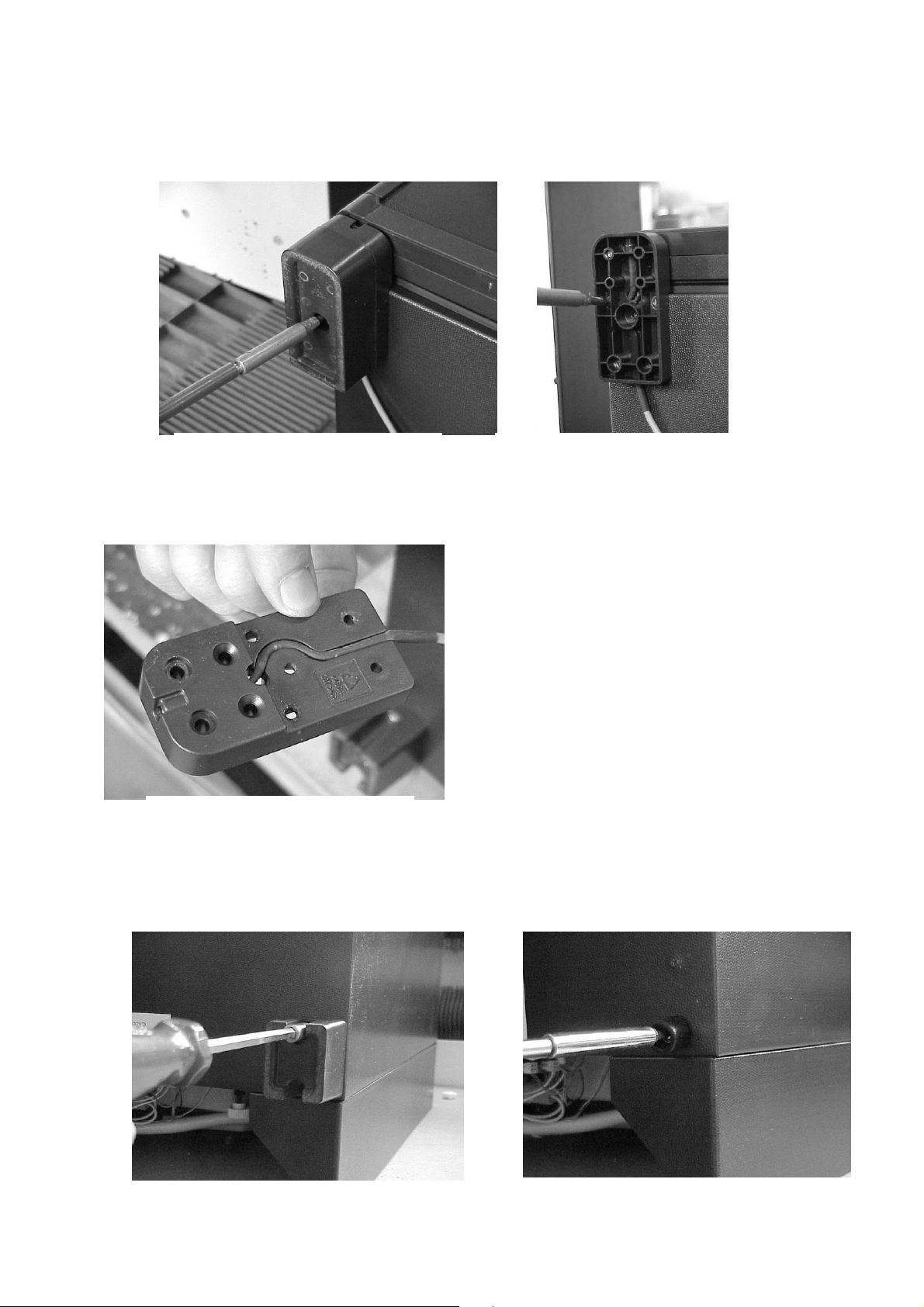
2.3.2.2.3. Replacing the heating cartridge
- Turn refrigerator on its door.
- Remove flange and electrical cover. (see 2.3.2.2., 2.2.2.)
- Remove PCB connector of heating cartridge from the motherboard (X3),
disassemble grounding. (Figure 54)
Figure 54
- Bend out horns designed to fasten the cover of boiler insulation. (Figure
55, 56)
- Remove upper and lower boiler covers. (Figure 57, 58)
Figure 55 Figure 56
Figure 57 Figure 58
- Twist boiler insulation, dislocate rims by carefully pressing cover, unbind
boiler insulation along with cover from under the boiler.
19
Page 20

(Figure 59, 60)
Figure 61
Figure 62
Figure 63
Figure 64
Figure 65
Figure 59 Figure 60
- Mark fastening position of heating cartridge on boiler with a permanent felt-
tip pen (in order to facilitate subsequent reassembly) (Figure 61)
- Remove fastening spring of heating cartridge. (Figure 62)
- Twist heating cartridge in the direction of the back panel. (Figure 63)
- Remove the clamp from the heating cartridge with 2 combination pliers.
(Figure 64)
- Restore clamps on the new heating cartridge up to the middle (45 mm
from upper edge), and level upper edge of heating cartridge with the pen
sign showing the position. By applying strength, press the clamp and apply
the heating cartridge to the boiler. (Figure 65)
20
Page 21

- Position the cartridge, refine position (cartridge rim must be 13 mm from
Figure 70
the median of boiler’s lowermost impression in the case of all versions)
- Twist cartridge in a way that it stands in the opposite direction of the
soaker.
(Figure 66)
- Restore boiler cover, clip together, twist to its place, restore boiler covers,
fasten by bending horns on cover. (Figure 67, 68, 69)
Figure 66
Figure 67 Figure 68 Figure 69
- Thread the fastening ring of heating cartridge cable to the cartridge cable,
clip spring on liquid heat exchanger. (Figure 70)
- Restore PCB connector to motherboard, connect grounding.
(see Figure 54)
- Restore electrical cover, flange, and fasten with screws. (see 2.3.2.2.,
2.2.3.)
- Turn refrigerator o its feet.
- Test electrical insulation resistance (with testing apparatus for 1000 V
electrical insulation resistance).
Insulation resistance is R
> 2Mohm
ins
21
Page 22

2.3.2.2.4. Replacing the Automatic Door Control LED
- Remove electrical cover (see 2.3.2.2.)
- Pull off PCB connector of automatic door control LED cable from
motherboard (X6). (Figure 71)
Figure 71
Figure 72
- Remove screws from LED cable fasteners on back panel and bottom
panel. (Figure 72)
- Turn refrigerator on its back.
- Unscrew and remove fastening screw of fott extension. (Figure 73)
Figure 73 Figure 74 Figure 75
- Remove the 3 screws from fastening foot, remove foot (Figure 74, 75)
- Remove LED cable from fastening foot groove, restoring new cable.
(Figure 75)
- Screwing on fastening foot and foot extension.
- Order LED cable on bottom panel and fasten in cable fastener.
- Connect PCB plug to motherboard, restore electrical cover.
- Order cable, fasten in cable fastener.
- Turn back refrigerator on its feet.
- Test electrical insulation resistance (with testing apparatus for 1000 V
electrical insulation resistance).
Insulation resistance is R
> 2Mohm
ins
- In case of conformance connect appliance to electrical supply, and check
operation the self-test of the electronics.
22
Page 23

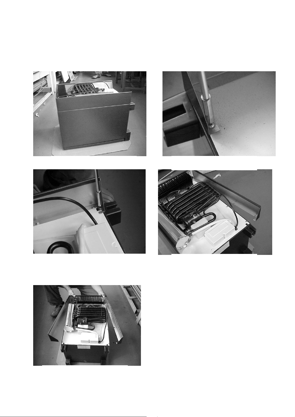
2.4. The cooling unit
2.4.1. Replacing the cooling unit
- Open refrigerator door.
- Remove cover panel from refrigerator. Remove evaporator board from
evaporator pipe, remove sensor tip from seating. (see 2.3.2.2.1.))
- Turn refrigerator to its door.
- Remove flange and electrical cover. (see 2.2.3., 2.3.2.2.)
- By pressing horns, lift Fuzzy III panel from its seating.
- Remove PCB connector of heating cartridge from Fuzzy III panel, and
disassemble heating cartridge as per 2.3.2.2.3..
Figure 77 Figure 76
- Remove cooling unit fastening screws, lift faulty cooling unit, and isolate.
(Figure 76, 77)
- Restore new unit to cabinet body.
Figure 78
Figure 79
- Place condensate evaporator on liquid heat exchanger, taking care that
end of condensate outlet pipe reaches the condensate evaporator.
(Figure 78, 79)
- Fasten cooling unit with screws.
- Assemble heating cartridge and boiler insulation as per 2.3.2.2.3.
- Restore heating cartridge PCB connector to Fuzzy III panel.
- Restore electrical cover, flange, fasten with screws. (see 2.3.2.2., 2.2.3.)
- Turn refrigerator on feet.
- Restore evaporator board, evaporator sensor. (see 2.3.2.2.1.)
- Test electrical insulation resistance (with testing apparatus for 1000 V
electrical insulation resistance).
Insulation resistance is R
> 2Mohm
ins
23
Page 24

2.5. Information:
Certain appliance versions do not contain all parts (lock, flange, automatic
door control, light). Sections of the instructions relevant to the above do not
apply to such appliance versions.
24
 Loading...