

Dometic PW1500, PW1750 Installation Manual
1
==
2.6m
3.0m
3.5m
4.0m
4.5m
5.0m
5.5m
6.0m
1215
1415
40
1585
120
1585
1250200 1010 1250
1500
1750
2450
240 1430
530
1500
1750
2450
1215
1415
1.
2.
2.
1.
280
32
4 5 6 7 8
9 10
11 12 13 14
15 16 17 18
19 20
22 23
21
1
15 – 20 Nm
PW1500, PW1750
1
2
5
6
3
4
8
9
7
0
ab c
2
www.dometic.com
Dometic WAECO International GmbH
Hollefeldstrasse 63
D-48282 Emsdetten
www.dometic.com
+12 Vg
bl
br
AB
1.
2.
Ø3 mm
4.
1.
2.
3.
Ø 3 mm
2.
1.
EN DE FR ES PT IT NL DA
bl Blue Blau Bleu Azul Azul Blu Blauw Blå
br Brown Braun Marron Marrón Castanh o Marrone Bruin Brun
SV NO FI RU PL CS SL EL
bl Blå Blå Sininen Синий Niebieski Modrá Modra Μπλε
br Brun Brun Ruskea Корич-
невый
Brązowy Hněda Rjavo Καφέ
j
k
hi
g
def l
m
4445101839 09/2016
PW1500, PW1750
ENDEFRESPTITNLDASVNOFIRUPLCSSL
EL
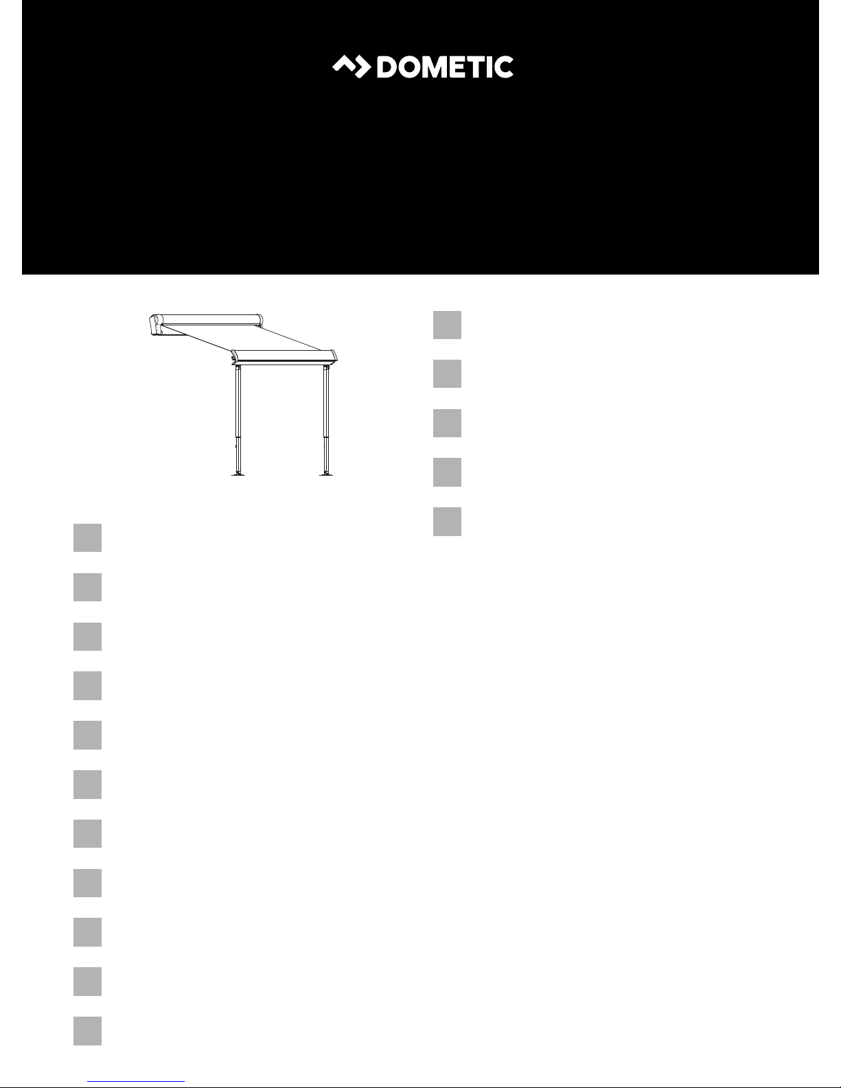
Awning
Installation Manual. . . . . . . . . . . . . . . . . . . . .3
AWNINGS
PERFECTWALL
Синусоидальный инвертор
Инструкция по монтажу. . . . . . . . . . . . . . 114
Markiza
Instrukcja montażu . . . . . . . . . . . . . . . . . . 125
Markýza
Návod k montáži. . . . . . . . . . . . . . . . . . . . 136
Markiza
Navodilo za montažo . . . . . . . . . . . . . . . . 146
Τέντα
Οδηγίες τοποθέτησης. . . . . . . . . . . . . . 156
Markise
Montageanleitung. . . . . . . . . . . . . . . . . . . . 13
Store extérieuru
Instructions de montage . . . . . . . . . . . . . . .23
Tol d o
Instrucciones de montaje . . . . . . . . . . . . . .33
Tol d o
Instruções de montagem . . . . . . . . . . . . . .43
Ten da da s ole
Indicazioni di montaggio . . . . . . . . . . . . . .53
Zonnescherm
Montagehandleiding . . . . . . . . . . . . . . . . .63
Markise
Monteringsvejledning. . . . . . . . . . . . . . . . .73
Markis
Monteringsanvisning. . . . . . . . . . . . . . . . . .83
Markise
Monteringsanvisning. . . . . . . . . . . . . . . . . .94
Markiisi
Asennusohje . . . . . . . . . . . . . . . . . . . . . . .104


EN
PW1500, PW1750
WARNING!
!
• This operating manual must be read and understood before
installation, set up, operation and servicing. This device must be
installed by a specialist. Improper installation can lead to serious
injury. Alterations to the device can be extremely dangerous and
lead to serious injury or damage to the device.
• Keep this operating manual with the device. The owner must read it
carefully.
Table of contents
1 Explanation of symbols. . . . . . . . . . . . . . . . . . . . . . . . . . . . . . . . . . . . . . . . . . .4
2 Important safety and installation instructions. . . . . . . . . . . . . . . . . . . . . . . . . .4
3 Scope of delivery . . . . . . . . . . . . . . . . . . . . . . . . . . . . . . . . . . . . . . . . . . . . . . .5
4 Accessories . . . . . . . . . . . . . . . . . . . . . . . . . . . . . . . . . . . . . . . . . . . . . . . . . . . .6
5 Intended use . . . . . . . . . . . . . . . . . . . . . . . . . . . . . . . . . . . . . . . . . . . . . . . . . . .6
6 Installing the awning . . . . . . . . . . . . . . . . . . . . . . . . . . . . . . . . . . . . . . . . . . . . .6
7 Disposal . . . . . . . . . . . . . . . . . . . . . . . . . . . . . . . . . . . . . . . . . . . . . . . . . . . . . .12
3

EN
Explanation of symbols PW1500, PW1750
1 Explanation of symbols
WARNING!
!
A
Safety instruction: Failure to observe this instruction can cause fatal or
serious injury.
NOTICE!
Failure to observe this instruction can cause material damage and impair
the function of the product.
NOTE
Supplementary information for operating the product.
I
2 Important safety and installation
instructions
Please observe the safety instructions and stipulations issued by the
vehicle manufacturer and service workshops.
The manufacturer accepts no liability for damage in the following cases:
• Faulty assembly or connection
• Damage to the product resulting from mechanical influences
• Alterations to the product without express permission from the manufacturer
• Use for purposes other than those described in the operating manual
WARNING!
!
• If you do not have sufficient technical knowledge for installing
components in vehicles, you should have a specialist fit the awning to
your vehicle.
4

EN
PW1500, PW1750 Scope of delivery
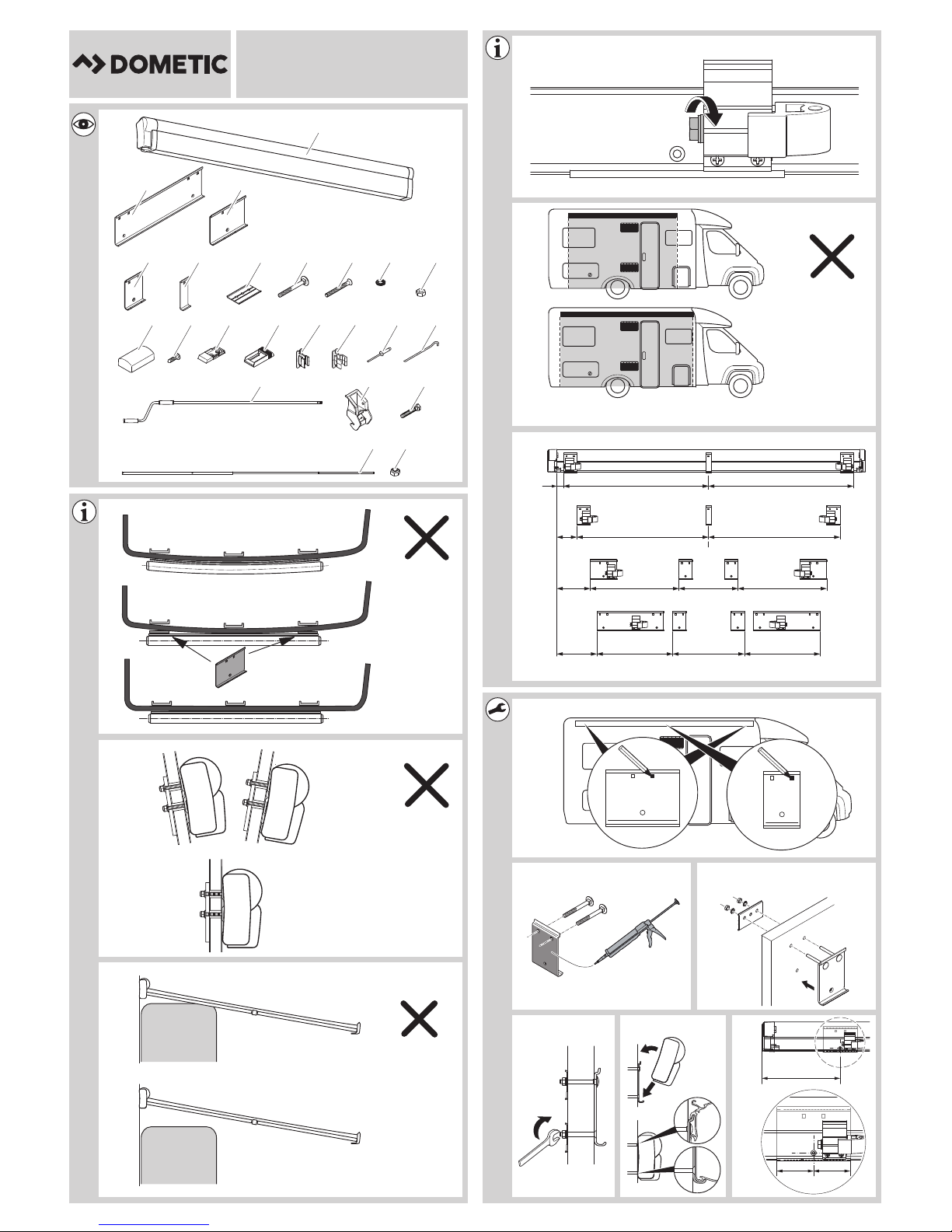
3Scope of delivery
No. in
fig. 1,
page 1
11x1x1xAwning
2 – – 2x Mounting plate (400 mm)
3 – 2x 2x Mounting plate (160 mm)
4 2x 2x – Mounting plate (80 mm)
5 1x – – Mounting plate (35 mm)
6 5x 8x 12x Counter plate
7 5x 8x 12x Square-head bolt
8 2x 4x 6x Countersunk bolt
9 7x 12x 18x Serrated lock washer
10 7x 12x 18x Hexagon nut
11 5x 8x 12x Cover for the counter plate
2.6 m,
3 m, 3.5 m
Awning width
4m,
4.5 m
5m,
5.5 m
Description
12 11x 14x 18x Self-tapping screw
13 2x 2x 2x Wall bracket (lower section)
14 2x 2x 2x Wall bracket (upper section)
15 1x 1x 1x Crank bracket (lower section)
16 1x 1x 1x Crank bracket (upper section)
17 4x 4x 4x Rivets
18 4x 4x 4x Pegs
19 1x 1x 1x Crank
20 – 1x 1x Latch for tensioning arm
21 – 1x 1x Hexagon head bolt
22 – 1x 1x Tensioning arm
23 – 1x 1x Hexagon nut with clamping part
5

EN
Accessories PW1500, PW1750
4Accessories
Available as accessories (not included in the scope of delivery):
Description Ref. no.
Dometic Light LK120
LED lighting with remote control for fitting on the awning
arms
Tie Down Kit
Fixing belts for the awning
If you have questions regarding the accessories, please contact your local service
partner.
9106504018
9103104000
5 Intended use
The PerfectWall PW1500, PW1750 awnings are suitable for installing on
motorhomes or caravans.
The awnings must only be used whilst the vehicle is stationary. Please observe the
operating manual.
6 Installing the awning
6.1 Required installation material
For the installation of the awning, you will need:
• Various tools, e.g. screwdriver
• A suitable flexible adhesive/sealant, e.g. Sikaflex
• A cleaning agent that is recommended for use with the adhesive
• A primer that is recommended for use with the adhesive
• Acid-free silicone
®
-252
6

EN
PW1500, PW1750 Installing the awning
6.2 Notes on the installation position
When choosing the installation location, observe the following:
WARNING!
!
A
• Keep a sufficient distance from objects or other vehicles. Once it is
retracted, it should be at least 40 cm away from other objects and
vehicles.
• Ensure the wall of the motorhome can safely take the weight of the
awning before installation. Otherwise, the awning may become
unstable and bend or break.
NOTICE!
• Make sure that the inner screw joints are accessible.
• Only attach the awning to flat and vertical wall surfaces (fig. 2 and
fig. 3, page 1). On curved wall surfaces, the mounting plates need to
be adequately lined under the fastening points.
• If there is insufficient space above the door after the awning is
mounted, the door must remain closed when retracting or extending
to avoid the door making contact with the arms or the front panel.
The required space depends on the design of the door (door width,
swing or sliding door) as well as the set awning angle of inclination
(fig. 4, page 1).
I
• The cables and cabinets in the interior of the vehicle may not be
damaged by drilling the holes.
NOTE
Ensure the user of the vehicle is aware that the screws on the rear hinge
(fig. 5, page 1) must be tightened up (see operating manual). The arms
must not bear any load. This must be done by the service partner.
7

EN
Installing the awning PW1500, PW1750
6.3 Installing the awning
During installation, observe the following general information:
• The awning can be attached in two ways:
– to the side of the vehicle using mounting plates
– to the existing piping rail on the side of the vehicle
• The mounting plates are bolted to the vehicle in the area of the rear hinge. In
addition, they are glued with installation adhesive (e.g. Sikaflex
product) to ensure the load is evenly spread and an optimal level of protection
from moisture is maintained.
• Observe the sealant manufacturer's instructions.
• Before installation, check the access to the screw joints. Make sure no cables or
cabinets are damaged when drilling.
• Contact your local service partner if you wish to have an angle of inclination
different to the default setting.
• If you want to use an awning tent with the awning at a later date, ensure that the
vent windows and hatches of the erected tent remain accessible when choosing
the awning size and installation position (fig. 6, page 1).
®
-221 or a similar
• Clean the adhesive surfaces on the mounting rails and the wall.
• Prepare the adhesive surfaces with the primer.
• After gluing, wait until the adhesive has set. For further details, please refer to the
information provided by the sealant manufacturer.
• Carefully seal the drill holes to prevent moisture from entering the motorhome
wall.
• Do not open the awning or leave it unattended, before the awning has been
fastened to the mounting rails.
• As part of the regular maintenance procedure, the screws on the rear hinge must
be tightened up by a service partner. Ensure the users of the vehicle are aware of
this.
8

EN
PW1500, PW1750 Installing the awning
Installing the awning with mounting plates
➤ Select the location of the installation.
In particular, check that there is enough space in the interior to mount the counter
plates at the points where the screws will be.
NOTE
I
➤ Align the mounting plates on the vehicle and mark where the holes are to be
drilled (fig. 8, page 1).
➤ At the marked points, drill holes with a diameter of 6.5 mm from the outside
through the external wall.
➤ Clean the outer sides of the mounting plates and the installation surface on the
vehicle.
Recommended mounting position for each counter plate: fig. 7,
page 1.
➤ Fill the drill holes in the vehicle wall with an acid-free silicone.
➤ Insert the square-head bolts through the relevant holes in the mounting plates
(fig. 9, page 1).
➤ To glue and seal, apply an elastic adhesive, such as Sikaflex
the back of the mounting plates (fig. 9, page 1).
➤ Place all of the mounting plates through the drill holes and fasten them with
counter plate, serrated lock washers and hexagon head bolts (fig. 0, page 1).
➤ Only for awnings with a width of 2.6 m to 3.5 m:
Fasten all of the mounting plates using a countersunk bolt, counter plate,
serrated lock washer and hexagon nut (fig. a, page 1).
➤ Only for awnings with a width of 4 m to 5.5 m:
Fasten the inner (narrow) mounting plates using a countersunk bolt, counter
plate, serrated lock washer and hexagon nut (fig. a, page 1).
➤ Wait until the glue has set. For further details, please refer to the information
provided by the sealant manufacturer.
®
-221 for example, to
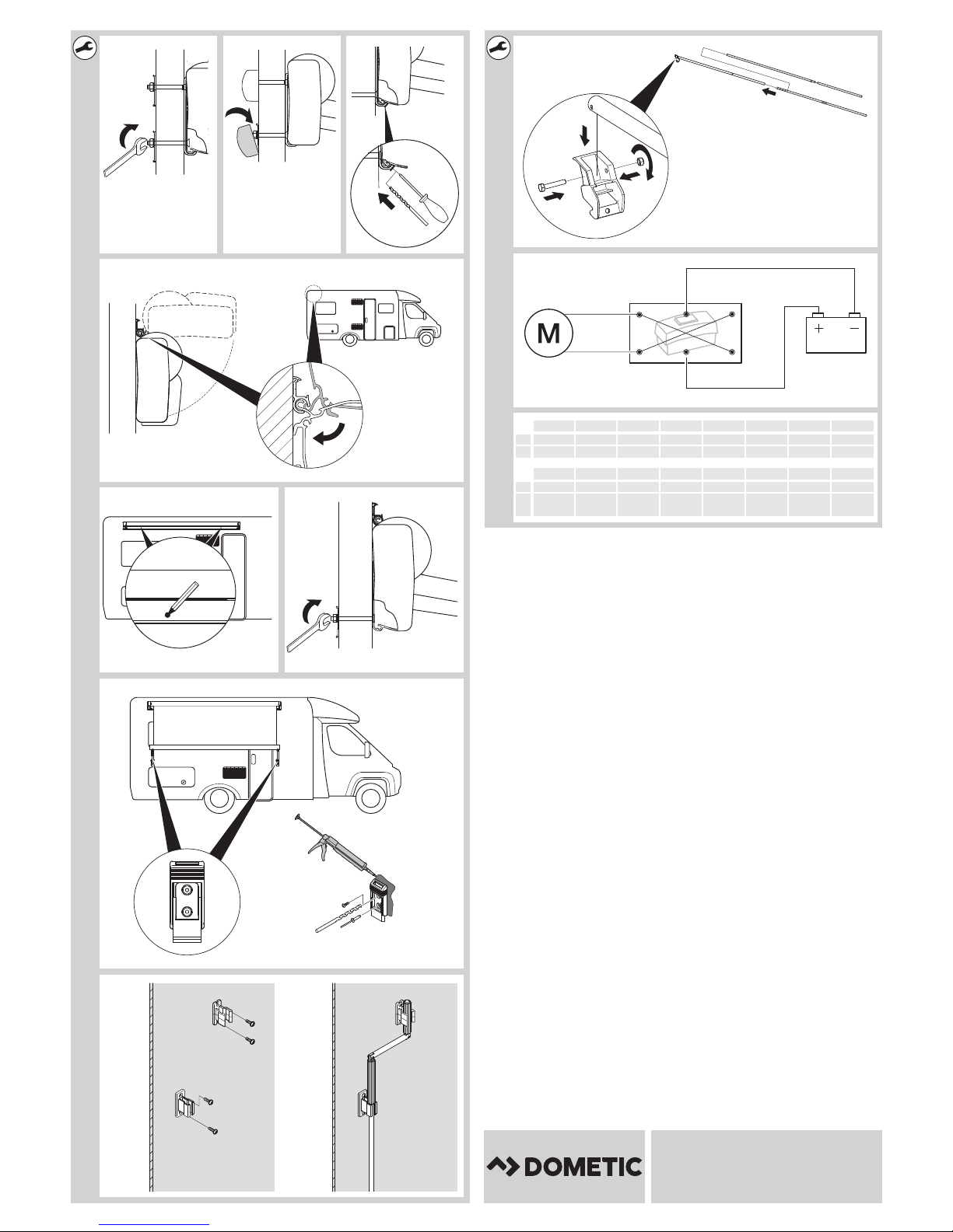
➤ Use two people to hook the awning on to the mounting plates (fig. b, page 1).
➤ Extend the awning about 50 cm using the crank.
9

EN
Installing the awning PW1500, PW1750
➤ Only for awnings with a width of 4 m to 5.5 m:
Drill one hole with a diameter of 6.5 mm through the left and the right side of the
awning. The hole has to be in a distance of 280 mm to the respective edge of the
awning and be on the same level as its counterpart in the long mounting plate
(fig. c, page 1).
➤ Only for awnings with a width of 4 m to 5.5 m:
Fasten the awning using a countersunk bolt, counter plate, serrated lock washer
and hexagon nut (fig. d, page 2).
➤ Insert the cover caps on the counter plates (fig. e, page 2).
➤ Drill two holes with a diameter of 3 mm through the awning and each of the long
mounting plates (fig. f, page 2).
➤ Drill one hole with a diameter of 3 mm through the awning and each of the short
mounting plates (fig. f, page 2).
➤ Fasten the awning with drill screws (fig. f, page 2).
➤ Retract the awning completely using the crank.
Installing awning on the piping rail
➤ Select the location of the installation.
In particular, check that there is enough space in the interior to mount the counter
plates at the points where the screws will be.
NOTE
I
➤ Use two people to hook the awning on to the piping rail.
➤ Extend the awning about 50 cm using the crank.
➤ Mark where the holes are to be drilled (fig. h, page 2).
➤ Retract the awning completely using the crank.
➤ Use two people to lift the awning from the piping rail.
Measure the recommended mounting position for each counter plate
against the drill hole in the lower section of the awning.
➤ At the marked points, drill holes with a diameter of 6.5 mm from the outside
through the external wall.
➤ Fill the drill holes in the vehicle wall with an acid-free silicone.
➤ Use two people to hook the awning on to the piping rail.
➤ Extend the awning about 50 cm using the crank.
10

EN
PW1500, PW1750 Installing the awning
➤ Fasten the awning using a countersunk bolt, counter plate, serrated lock washer
and hexagon nut (fig. i, page 2).
➤ Insert the cover caps on the counter plates (fig. e, page 2).
➤ Retract the awning completely using the crank.
Installing the wall bracket
The wall bracket must be installed if the awning is to be attached to the side of the
vehicle when extended.
➤ Select the location of the installation.
➤ Mark where the holes are to be drilled.
➤ At the marked points, drill holes with a diameter of 3 mm from the outside into
the external wall (fig. j, page 2).
➤ Put the upper and lower sections of the wall bracket together.
➤ Clean the outer sides of the lower section and the installation surface in the
vehicle.
NOTE
I
➤ To glue and seal, apply an elastic adhesive, such as Sikaflex®-221 for example, to
the back of the wall bracket.
➤ Fasten the wall bracket with drill screws (fig. j, page 2).
or
➤ Rivet the wall bracket (fig. j, page 2).
Installing the crank bracket
➤ Mount the wall bracket for the crank at a suitable location inside the vehicle
(fig. k, page 2).
Make sure that no glue gets on to the movable upper section of the wall
bracket.
11

EN
Disposal PW1500, PW1750
Mounting the tensioning arm
Awnings with a width of 4 m to 5.5 m must be secured with a tensioning arm.
➤ Attach the pre-drilled end of the tensioning arm to the latch for the tensioning
arm using the hexagon head bolt and the hexagon nut with clamping part
(fig. l, page 2).
➤ Insert the lower section of the tensioning arm into the upper section (fig. l,
page 2).
6.4 Connecting the motor (optional)
➤ Connect the motor according to fig. m, page 2.
7Disposal
➤ Place the packaging material in the appropriate recycling waste bins wherever
possible.
If you wish to finally dispose of the product, ask your local recycling centre
or specialist dealer for details about how to do this in accordance with the
M
applicable disposal regulations.
12

DE
PW1500, PW1750
WARNUNG!
!
• Diese Anleitung muss vor der Installation, dem Einrichten, dem
Betrieb und der Wartung gelesen und verstanden werden. Dieses
Gerät muss von einer Fachkraft installiert werden. Eine fehlerhafte
Installation kann zu schweren Verletzungen führen. Umbauten am
Gerät können äußerst gefährlich werden und zu schweren
Verletzungen oder zu Geräteschäden führen.
• Diese Anleitung muss beim Gerät verbleiben. Der Besitzer muss sie
aufmerksam lesen.
Inhaltsverzeichnis
1 Erklärung der Symbole . . . . . . . . . . . . . . . . . . . . . . . . . . . . . . . . . . . . . . . . . .14
2 Wichtige Sicherheits- und Einbauhinweise . . . . . . . . . . . . . . . . . . . . . . . . . .14
3 Lieferumfang . . . . . . . . . . . . . . . . . . . . . . . . . . . . . . . . . . . . . . . . . . . . . . . . . .15
4 Zubehör. . . . . . . . . . . . . . . . . . . . . . . . . . . . . . . . . . . . . . . . . . . . . . . . . . . . . .16
5 Bestimmungsgemäßer Gebrauch . . . . . . . . . . . . . . . . . . . . . . . . . . . . . . . . .16
6 Markise montieren . . . . . . . . . . . . . . . . . . . . . . . . . . . . . . . . . . . . . . . . . . . . .16
7 Entsorgung . . . . . . . . . . . . . . . . . . . . . . . . . . . . . . . . . . . . . . . . . . . . . . . . . . 22
13

DE
Erklärung der Symbole PW1500, PW1750
1 Erklärung der Symbole
WARNUNG!
!
A
Sicherheitshinweis: Nichtbeachtung kann zu Tod oder schwerer
Verletzung führen.
ACHTUNG!
Nichtbeachtung kann zu Materialschäden führen und die Funktion des
Produktes beeinträchtigen.
HINWEIS
Ergänzende Informationen zur Bedienung des Produktes.
I
2 Wichtige Sicherheits- und
Einbauhinweise
Beachten Sie die vom Fahrzeughersteller und vom Kfz-Handwerk
vorgeschriebenen Sicherheitshinweise und Auflagen!
Der Hersteller übernimmt in folgenden Fällen keine Haftung für Schäden:
• Montage- oder Anschlussfehler
• Beschädigungen am Produkt durch mechanische Einflüsse
• Veränderungen am Produkt ohne ausdrückliche Genehmigung vom Hersteller
• Verwendung für andere als die in der Anleitung beschriebenen Zwecke
WARNUNG!
!
• Wenn Sie nicht über ausreichende technische Kenntnisse zum
Einbauen von Komponenten in Fahrzeugen verfügen, sollten Sie sich
die Markise von einem Fachmann ans Fahrzeug montieren lassen.
14

DE
PW1500, PW1750 Lieferumfang
3 Lieferumfang
Nr. in
Abb. 1,
Seite 1
1 1x 1x 1x Markise
2 – – 2x Montageplatte (400 mm)
3 – 2x 2x Montageplatte (160 mm)
4 2x 2x – Montageplatte (80 mm)
5 1x – – Montageplatte (35 mm)
6 5x 8x 12x Gegenplatte
7 5x 8x 12x Vierkantschraube
8 2x 4x 6x Senkschraube
9 7x 12x 18x Fächerscheibe
10 7x 12x 18x Sechskantmutter
11 5x 8x 12x Abdeckung für Gegenplatte
2,6 m,
3 m, 3,5 m
Markisenbreite
Bezeichnung
4 m, 4,5 m 5 m, 5,5 m
12 11x 14x 18x Bohrschraube
13 2x 2x 2x Wandhalterung (unterer Teil)
14 2x 2x 2x Wandhalterung (oberer Teil)
15 1x 1x 1x Kurbelhalterung (unterer Teil)
16 1x 1x 1x Kurbelhalterung (oberer Teil)
17 4x 4x 4x Niete
18 4x 4x 4x Hering
19 1x 1x 1x Kurbel
20 – 1x 1x Arretierung für Spannstange
21 – 1x 1x Sechskantschraube
22 – 1x 1x Spannstange
23 – 1x 1x Sechskantmutter mit Klemmteil
15

DE
Zubehör PW1500, PW1750
4Zubehör
Als Zubehör erhältlich (nicht im Lieferumfang enthalten):
Bezeichnung Artikelnummer
Dometic Light LK120
LED-Beleuchtung mit Fernbedienung zur Montage an die
Markisenarme
Tie Down Kit
Gurte zum Abspannen der Markise
Bei Fragen zu Zubehör wenden Sie sich bitte an Ihren Service-Partner.
9106504018
9103104000
5 Bestimmungsgemäßer Gebrauch
Die Markisen PerfectWall PW1500, PW1750 sind geeignet zum Anbau an
Wohnmobile oder Wohnwagen.
Die Markisen dürfen nur im Stand benutzt werden. Bitte beachten Sie die
Bedienungsanleitung.
6Markise montieren
6.1 Benötigtes Montagematerial
Für die Montage der Markise benötigen Sie:
• Diverses Werkzeug, z. B. Schraubendreher
• Geeigneter elastischer Kleber/Dichtmittel wie z. B. Sikaflex
• Reiniger, der zur Verwendung mit dem Kleber empfohlen ist
• Primer, der zur Verwendung mit dem Kleber empfohlen ist
• Säurefreies Silikon
®
-252
16

DE
PW1500, PW1750 Markise montieren
6.2 Hinweise zum Montageort
Beachten Sie bei der Wahl des Einbauortes Folgendes:
WARNUNG!
!
A
• Halten Sie genügend Abstand zu Gegenständen oder anderen
Fahrzeugen. Nach dem Ausfahren muss ringsum ein Mindestabstand
zu anderen Gegenständen oder Fahrzeugen von 40 cm sein.
• Stellen Sie vor der Installation sicher, dass die Wohnmobilwand die
Markise sicher tragen kann. Sonst kann die Markise instabil werden
und sich verbiegen oder abbrechen.
ACHTUNG!
• Achten Sie darauf, dass die Innenverschraubungen zugänglich sind.
• Montieren Sie die Markise nur an planen und lotrechten Wandflächen
(Abb. 2 und Abb. 3, Seite 1). Bei gewölbten Wandflächen
müssen Sie die Montageplatten an den Befestigungsstellen
ausreichend unterfüttern.
• Falls nach dem Einbau der Markise kein ausreichender Freiraum über
der Tür verbleibt, muss die Tür während des Ein- oder Ausfahrens
geschlossen bleiben, um einen Kontakt der Tür mit den Armen oder
der Frontleiste zu vermeiden.
Der benötigte Freiraum hängt von der Bauart der Tür (Türbreite,
Schwenk- oder Schiebetür) sowie dem eingestellten Neigungswinkel
der Markise ab (Abb. 4, Seite 1).
I
• Leitungen und Einbauschränke im Fahrzeuginnenraum dürfen beim
Bohren nicht beschädigt werden.
HINWEIS
Weisen Sie den Benutzer des Fahrzeugs darauf hin, dass die Schrauben
am Schultergelenk (Abb. 5, Seite 1) nachgezogen werden müssen
(siehe Bedienungsanleitung). Die Arme müssen lastfrei sein. Dies muss
durch den Service-Partner erfolgen.
17

DE
Markise montieren PW1500, PW1750
6.3 Markise montieren
Beachten Sie bei der Montage folgenden allgemeinen Hinweise:
• Die Markise kann auf zwei Arten befestigt werden:
– mit Montageplatten an die Fahrzeugwand
– an eine vorhandene Kederschiene an der Fahrzeugwand
• Die Montageplatten werden im Bereich der Schultergelenke am Fahrzeug
verschraubt. Zusätzlich werden sie mit Montagekleber (z. B. Sikaflex
ein vergleichbares Produkt) verklebt, um eine gleichmäßige Lasteinleitung zu
erhalten und einen optimalen Schutz vor Feuchtigkeit zu erreichen.
• Beachten Sie die Hinweise des Dichtmittel-Herstellers.
• Prüfen Sie vor der Montage die Zugänglichkeit der Verschraubungen. Achten
Sie darauf, dass beim Bohren keine Leitungen oder Einbauschränke beschädigt
werden.
• Sollten Sie eine anderen Neigungswinkeleinstellung wünschen als ab Werk
vorgesehen, wenden Sie sich an Ihren Service-Partner.
®
-221 oder
• Falls Sie später ein Markisenvorzelt mit der Markise verwenden wollen, sollten
Sie bei der Auswahl der Markisengröße und Montageposition darauf achten,
dass Ausstellfenster und Klappen auch bei montiertem Zelt zugänglich bleiben
(Abb. 6, Seite 1).
• Reinigen Sie die Klebeflächen auf den Montageschienen und der Wand.
• Bereiten Sie die Klebeflächen mit dem Primer vor.
• Warten Sie nach dem Kleben, bis der Kleber ausgehärtet ist. Nähere Angaben
entnehmen Sie den Informationen des Dichtmittel-Herstellers.
• Dichten Sie die Bohrungen sorgfältig ab, um Feuchtigkeit in der
Wohnmobilwand zu verhindern.
• Fahren Sie die Markise nicht aus und lassen Sie sie nicht unbeaufsichtigt, solange
die Markise noch nicht an den Montageschienen fixiert ist.
• Die Schrauben der Schultergelenke müssen im Rahmen einer regelmäßigen
Wartung von einem Service-Partner nachgezogen werden. Weisen Sie die
Benutzer des Fahrzeuges hierauf hin.
18

DE
PW1500, PW1750 Markise montieren
Markise mit Montageplatten montieren
➤ Legen Sie den Montageort fest.
Prüfen Sie insbesondere, ob an den Stellen, an denen die Verschraubungen sein
werden, genügend Platz für die Montage der Gegenplatten im Innenraum ist.
HINWEIS
Empfohlene Montageposition für jede Gegenplatte: Abb. 7, Seite 1.
I
➤ Richten Sie die Montageplatten am Fahrzeug aus und zeichnen Sie die
Bohrungen vor (Abb. 8, Seite 1).
➤ Bohren Sie an den angezeichneten Stellen von außen Löcher mit einem
Durchmesser von 6,5 mm durch die Außenwand.
➤ Reinigen Sie die Außenseiten der Montageplatten und die Montagefläche am
Fahrzeug.
➤ Füllen Sie die Bohrungen in der Fahrzeugwand mit säurefreiem Silikon.
➤ Stecken Sie die Vierkantschrauben durch die entsprechenden Löcher der
Montageplatten (Abb. 9, Seite 1).
➤ Tragen Sie zum Kleben und Abdichten auf die Rückseite der Montageplatten
einen elastischen Kleber wie z. B. Sikaflex
➤ Stecken Sie alle Montageplatten durch die Bohrungen und kontern Sie diese mit
Gegenplatte, Fächerscheibe und Sechskantmutter (Abb. 0, Seite 1).
➤ Nur bei Markisen mit einer Breite von 2,6 m bis 3,5 m:
Verschrauben Sie alle Montageplatten mit Senkschraube, Gegenplatte,
Fächerscheibe und Sechskantmutter (Abb. a, Seite 1).
➤ Nur bei Markisen mit einer Breite von 4 m bis 5,5 m:
Verschrauben Sie die inneren (schmalen) Montageplatten mit Senkschraube,
Gegenplatte, Fächerscheibe und Sechskantmutter (Abb. a, Seite 1).
➤ Warten Sie, bis der Kleber ausgehärtet ist. Nähere Angaben entnehmen Sie den
Informationen des Dichtmittel-Herstellers.
➤ Hängen Sie die Markise mit zwei Personen in die Montageplatten (Abb. b,
Seite 1).
®
-221 auf (Abb. 9, Seite 1).
➤ Fahren Sie die Markise mit der Kurbel etwa 50 cm aus.
19

DE
Markise montieren PW1500, PW1750
➤ Nur bei Markisen mit einer Breite von 4 m bis 5,5 m:
Bohren Sie jeweils ein Loch mit einem Durchmesser von 6,5 mm durch die rechte
und die linke Seite der Markise. Das Loch muss einen Abstand von 280 mm zum
jeweiligen Rand der Markise haben und sich auf gleicher Höhe befinden wie das
Gegenstück in der langen Montageplatte (Abb. c, Seite 1).
➤ Nur bei Markisen mit einer Breite von 4 m bis 5,5 m:
Verschrauben Sie die Markise mit Senkschraube, Gegenplatte, Fächerscheibe
und Sechskantmutter (Abb. d, Seite 2).
➤ Stecken Sie die Abdeckkappen auf die Gegenplatten (Abb. e, Seite 2).
➤ Bohren Sie jeweils zwei Löcher mit einem Durchmesser von 3 mm durch die
Markise und die langen Montageplatten (Abb. f, Seite 2).
➤ Bohren Sie jeweils ein Loch mit einem Durchmesser von 3 mm durch die Markise
und die schmalen Montageplatten (Abb. f, Seite 2).
➤ Verschrauben Sie die Markise mit Bohrschrauben (Abb. f, Seite 2).
➤ Fahren Sie die Markise mit der Kurbel komplett ein.
Markise an Kederschiene montieren
➤ Legen Sie den Montageort fest.
Prüfen Sie insbesondere, ob an den Stellen, an denen die Verschraubungen sein
werden, genügend Platz für die Montage der Gegenplatten im Innenraum ist.
HINWEIS
I
➤ Hängen Sie die Markise mit zwei Personen in die Kederschiene (Abb. g,
Seite 2).
➤ Fahren Sie die Markise mit der Kurbel etwa 50 cm aus.
➤ Zeichnen Sie die Bohrungen vor (Abb. h, Seite 2).
➤ Fahren Sie die Markise mit der Kurbel komplett ein.
Die empfohlene Montageposition für jede Gegenplatte messen Sie an
den Bohrungen im unteren Teil der Markise.
➤ Heben Sie die Markise mit zwei Personen aus der Kederschiene.
➤ Bohren Sie an den angezeichneten Stellen von außen Löcher mit einem
Durchmesser von 6,5 mm durch die Außenwand.
➤ Füllen Sie die Bohrungen in der Fahrzeugwand mit säurefreiem Silikon.
➤ Hängen Sie die Markise mit zwei Personen in die Kederschiene.
20

DE
PW1500, PW1750 Markise montieren
➤ Fahren Sie die Markise mit der Kurbel etwa 50 cm aus.
➤ Verschrauben Sie die Markise mit Senkschraube, Gegenplatte, Fächerscheibe
und Sechskantmutter (Abb. i, Seite 2).
➤ Stecken Sie die Abdeckkappen auf die Gegenplatten (Abb. e, Seite 2).
➤ Fahren Sie die Markise mit der Kurbel komplett ein.
Wandhalterung montieren
Wenn die Markise im ausgefahrenen Zustand an der Fahrzeugwand befestigt
werden soll, muss die Wandhalterung montiert werden.
➤ Legen Sie den Montageort fest.
➤ Zeichnen Sie die Bohrungen vor.
➤ Bohren Sie an den angezeichneten Stellen von außen Löcher mit einem
Durchmesser von 3 mm in die Außenwand (Abb. j, Seite 2).
➤ Stecken Sie das untere und das obere Teil der Wandhalterung zusammen.
➤ Reinigen Sie die Außenseiten des unteren Teils der Wandhalterung und die
Montagefläche am Fahrzeug.
HINWEIS
I
➤ Tragen Sie zum Kleben und Abdichten auf die Rückseite der Wandhalterung
einen elastischen Kleber wie z. B. Sikaflex
➤ Verschrauben Sie die Wandhalterung mit Bohrschrauben (Abb. j, Seite 2).
oder
➤ Vernieten Sie die Wandhalterung (Abb. j, Seite 2).
Kurbelhalterung montieren
➤ Montieren Sie die Wandhalterung für die Kurbel an einer geeigneten Stelle
innerhalb des Fahrzeugs (Abb. k, Seite 2).
Stellen Sie sicher, dass kein Kleber an das bewegliche obere Teil der
Wandhalterung gerät.
®
-221 auf.
21

DE
Entsorgung PW1500, PW1750
Spannstange montieren
Markisen mit einer Breite von 4 m bis 5,5 m müssen mit einer Spannstange gesichert
werden.
➤ Befestigen Sie das vorgebohrte Ende der Spannstange mit der
Sechskantschraube und der Sechskantmutter mit Klemmteil an der Arretierung
für Spannstange (Abb. l, Seite 2).
➤ Setzen Sie den unteren Teil der Spannstange in den oberen Teil der Spannstange
ein (Abb. l, Seite 2).
6.4 Motor anschließen (optional)
➤ Schließen Sie den Motor gemäß Abb. m, Seite 2 an.
7Entsorgung
➤ Geben Sie das Verpackungsmaterial möglichst in den entsprechenden
Recycling-Müll.
Wenn Sie das Produkt endgültig außer Betrieb nehmen, informieren Sie
sich bitte beim nächsten Recyclingcenter oder bei Ihrem Fachhändler
M
über die zutreffenden Entsorgungsvorschriften.
22

FR
PW1500, PW1750
AVERTISSEMENT !
!
• Ce manuel doit être lu et compris avant l'installation, la mise en
place, le fonctionnement et la maintenance. Cet appareil doit être
installé par un technicien agréé. Une installation erronée peut
entraîner de graves blessures. Des modifications de l'appareil
peuvent s'avérer extrêmement dangereuses et provoquer de graves
blessures ou des dommages de l'appareil.
• Ce manuel doit rester à proximité de l'appareil. Le propriétaire doit
le lire attentivement.
Sommaire
1 Explication des symboles . . . . . . . . . . . . . . . . . . . . . . . . . . . . . . . . . . . . . . . 24
2 Consignes de sécurité et instructions de montage importantes . . . . . . . . 24
3 Contenu de la livraison . . . . . . . . . . . . . . . . . . . . . . . . . . . . . . . . . . . . . . . . . 25
4 Accessoires . . . . . . . . . . . . . . . . . . . . . . . . . . . . . . . . . . . . . . . . . . . . . . . . . . 26
5 Usage conforme . . . . . . . . . . . . . . . . . . . . . . . . . . . . . . . . . . . . . . . . . . . . . . 26
6 Montage du store extérieur . . . . . . . . . . . . . . . . . . . . . . . . . . . . . . . . . . . . . 26
7 Retraitement . . . . . . . . . . . . . . . . . . . . . . . . . . . . . . . . . . . . . . . . . . . . . . . . . 32
23

FR
Explication des symboles PW1500, PW1750
1 Explication des symboles
AVERTISSEMENT !
!
A
Consigne de sécurité : le non-respect de ces consignes peut entraîner
la mort ou de graves blessures.
AVIS !
Le non-respect de ces consignes peut entraîner des dommages
matériels et des dysfonctionnements du produit.
REMARQUE
Informations complémentaires sur l'utilisation du produit.
I
2 Consignes de sécurité et instructions de
montage importantes
Respectez les consignes de sécurité et autres prescriptions imposées par
le fabricant du véhicule et par les professionnels de l’automobile !
Le fabricant décline toute responsabilité pour des dommages dans les cas suivants :
• des défauts de montage ou de raccordement
• des influences mécaniques ayant endommagé le matériel
• des modifications apportées au produit sans autorisation explicite de la part du
fabricant
• une utilisation différente de celle décrite dans la notice
AVERTISSEMENT !
!
• Si vos connaissances techniques en matière d'installation d'éléments
dans un véhicule sont insuffisantes, nous vous recommandons de faire
installer l'auvent par un spécialiste.
24

FR
PW1500, PW1750 Contenu de la livraison
3 Contenu de la livraison
N° dans
fig. 1,
page 1
1 1x 1x 1x Store extérieur
2 – – 2x Plaque de montage (400 mm)
3 – 2x 2x Plaque de montage (160 mm)
4 2x 2x – Plaque de montage (80 mm)
5 1x – – Plaque de montage (35 mm)
6 5x 8x 12x Plaques de maintien
7 5x 8x 12x Boulon à tête carrée
8 2x 4x 6x Vis à tête conique
9 7x 12x 18x Rondelle en éventail
10 7x 12x 18x Écrou hexagonal
11 5x 8x 12x Cache pour plaque de maintien
Largeur du store extérieur
2,6 m,
3 m, 3,5 m
4 m, 4,5 m 5 m, 5,5 m
Désignation
12 11x 14x 18x Vis perceuse
13 2x 2x 2x Support mural (partie inférieure)
14 2x 2x 2x Support mural (partie supérieure)
15 1x 1x 1x Support de manivelle (partie
inférieure)
16 1x 1x 1x Support de manivelle (partie
supérieure)
17 4x 4x 4x Rivet
18 4x 4x 4x Sardine
19 1x 1x 1x Manivelle
20 – 1x 1x Blocage pour barre de serrage
21 – 1x 1x Vis six pans
22 – 1x 1x Barre de serrage
23 – 1x 1x Écrou six pans avec pièce de
serrage
25

FR
Accessoires PW1500, PW1750
4Accessoires
Disponibles en accessoires (non compris dans la livraison) :
Désignation Numéro de produit
Dometic Light LK120
Éclairage DEL avec télécommande, à monter sur les bras du
store extérieur
Kit d'attaches
Sangle permettant de tendre le store extérieur
En cas de questions concernant les accessoires, veuillez vous adresser à votre
partenaire de service après-vente.
9106504018
9103104000
5Usage conforme
Les stores extérieurs PerfectWall PW1500 et PW 1750 sont conçus pour être montés
sur des camping-cars ou des caravanes.
Les stores extérieurs doivent être utilisés à l'arrêt uniquement. Veuillez respecter les
consignes du manuel d'utilisation.
6 Montage du store extérieur
6.1 Matériel de montage nécessaire
Pour le montage de la gouttière, vous avez besoin des éléments suivants :
• Divers outils, p. ex. tournevis
• Colle élastique/produit d'étanchéité adapté comme p. ex. Sikaflex
• Détergent recommandé pour l'utilisation avec la colle
• Couche d'apprêt recommandée pour l'utilisation avec la colle
• Silicone non acide
®
-252
26

FR
PW1500, PW1750 Montage du store extérieur
6.2 Consignes relatives au lieu de montage
Pour le choix de l'emplacement de montage, tenez compte des remarques
suivantes :
AVERTISSEMENT !
!
A
• Respectez une distance suffisante par rapport aux objets ou aux autres
véhicules. Une fois le store extérieur déplié, la distance minimale avec
les autres objets ou véhicules, tout autour du store extérieur, doit être
de 40 cm.
• Assurez-vous avant l'installation que la paroi du camping-car peut
soutenir le store extérieur en toute sécurité. Dans le cas contraire, le
store extérieur peut devenir instable et se courber ou se casser.
AVIS !
• Veillez à ce que les vissages internes soient accessibles.
• Montez le store extérieur uniquement sur des surfaces murales planes
et d'aplomb (fig. 2 et fig. 3, page 1). En cas de parois bombées,
vous devez placer suffisamment d'isolant sous les plaques de
montage aux endroits de fixation.
• Si après le montage du store extérieur il ne reste pas d'espace suffisant
au-dessus de la porte, la porte doit rester fermée pendant que le store
extérieur est déplié ou replié, afin d'éviter le contact de la porte avec
les bras ou la barre frontale.
L'espace libre nécessaire dépend du type de construction de la porte
(largeur de la porte, porte battante ou coulissante) ainsi que de l'angle
d'inclinaison réglé pour le store extérieur (fig. 4, page 1).
• Les conduites et les meubles encastrés dans l'habitacle du véhicule ne
doivent pas être endommagés lors du perçage.
REMARQUE
Indiquez à l'utilisateur du véhicule que les vis de l'articulation (fig. 5,
I
page 1) doivent être resserrées (voir le manuel d'utilisation). Les bras ne
doivent supporter aucune charge. Cette opération doit être réalisée par
le partenaire de service.
27

FR
Montage du store extérieur PW1500, PW1750
6.3 Montage du store extérieur
Tenez compte des remarques générales suivantes lors du montage :
• Le store extérieur peut être fixé de deux façons :
– avec des plaques de montage sur la paroi du véhicule
– sur un rail à bourrelet présent sur la paroi du véhicule
• les plaques de montage se vissent au niveau des articulations, sur le véhicule.
Elles sont de plus collées avec une colle de montage (p. ex. Sikaflex
produit similaire) afin d'obtenir une répartition uniforme de la charge et une
protection optimale contre l'humidité.
• Veuillez tenir compte des recommandations du fabricant du produit
d'étanchéité.
• Avant le montage, veuillez vérifier que les raccords vissés sont accessibles.
Veillez à ce qu'aucun câble ou caisson encastré ne soit endommagé lors du
perçage.
• Si vous souhaitez régler un autre angle d'inclinaison que celui prévu en usine,
adressez-vous à votre partenaire de service après-vente.
®
-221 ou un
• Si vous souhaitez utiliser plus tard un auvent avec le store extérieur, veillez, lors
du choix de la taille du store et de la position de montage, à ce que les baies
projetables et les clapets restent accessibles même lorsque l'auvent est monté
(fig. 6, page 1).
• Nettoyez les surfaces de collage sur les rails de montage et le mur.
• Préparez les surfaces de collage avec la couche d'apprêt.
• Après le collage, attendez que la colle ait durci. Pour des indications plus
précises, consultez les informations du fabricant du produit d'étanchéité.
• Colmatez soigneusement les perçages, afin d'éviter que l'humidité ne pénètre
dans la paroi de la caravane.
• Ne dépliez pas le store extérieur et ne le laissez pas sans surveillance tant qu'il
n'est pas fixé aux rails de montage.
• Les vis des articulations doivent être resserrées par un partenaire de service
après-vente dans le cadre d'une maintenance régulière. Avertissez les utilisateurs
du véhicule à ce sujet.
28
 Loading...