

Dometic PerfectWall PW 3800 Installation Manua
1
2
5
6
3
4
8
9
7
0
ab
PW3800
32
4 5 6
9 10 11 12
14 15 16
13
15 – 20 Nm
1
7 8
19
17
18
4.0m
4.5m
5.0m
5.5m
6.0m
40
40
40
200
200
1315
1490
1640
1705
1880
1200
1350
1550
1600
1750
1315
1490
1640
1705
1880
40
40
40
200
200
1.
2.
2.
1.
1
Dometic WAECO International GmbH
Hollefeldstrasse 63
D-48282 Emsdetten
dometic.com
AB
og
rd
bk
rd
bk
bu
T15A
bn
T3A
D+
bu
bn
bu
bn
2
4
3
5
6
7
8
8
10
11
1
+12 Vg
2
1.
2.
Ø3 mm
Ø 3 mm
1
2
3
1
1
1
2
3
f
e
cd g
hi
2
4445102497 0700298 03/2018
EN
DE
FR
ES
PT
IT
NL
DA
SV
NO
FI
RU
PL
CS
SL
EL
AWNINGS
PERFECTWALL
PW3800
Awning
Installation Manual. . . . . . . . . . . . . . . . . . . . .3
Markise
Montageanleitung. . . . . . . . . . . . . . . . . . . . 14
Store extérieuru
Instructions de montage . . . . . . . . . . . . . . .25
To l d o
Instrucciones de montaje . . . . . . . . . . . . . .36
To l d o
Instruções de montagem . . . . . . . . . . . . . .47
Ten da d a so le
Indicazioni di montaggio . . . . . . . . . . . . . .58
Zonnescherm
Montagehandleiding . . . . . . . . . . . . . . . . .69
Markise
Monteringsvejledning. . . . . . . . . . . . . . . . .80
Markis
Monteringsanvisning. . . . . . . . . . . . . . . . . . 91
Markise
Monteringsanvisning. . . . . . . . . . . . . . . . . 101
Markiisi
Asennusohje . . . . . . . . . . . . . . . . . . . . . . . .111
Синусоидальный инвертор
Инструкция по монтажу. . . . . . . . . . . . . . 121
Markiza
Instrukcja montażu . . . . . . . . . . . . . . . . . . 132
Markýza
Návod k montáži. . . . . . . . . . . . . . . . . . . . 143
Markiza
Navodilo za montažo . . . . . . . . . . . . . . . . 153
ȉȑȞIJĮ
ȅįȘȖȓİȢ IJȠʌȠșȑIJȘıȘȢ. . . . . . . . . . . . . . 163


EN
PW3800 Explanation of symbols
WARNING!
!
• This instruction manual must be read and understood before
installation, set up, operation and servicing. This device must be
installed by a specialist. Improper installation can lead to serious
injury. Alterations to the device can be extremely dangerous and
lead to serious injury or damage to the device.
• Keep this operating manual with the device. The owner must read it
carefully.
Table of contents
1 Explanation of symbols. . . . . . . . . . . . . . . . . . . . . . . . . . . . . . . . . . . . . . . . . . .3
2 Important safety and installation instructions. . . . . . . . . . . . . . . . . . . . . . . . . .4
3 Scope of delivery . . . . . . . . . . . . . . . . . . . . . . . . . . . . . . . . . . . . . . . . . . . . . . .4
4 Accessories . . . . . . . . . . . . . . . . . . . . . . . . . . . . . . . . . . . . . . . . . . . . . . . . . . . .5
5 Intended use . . . . . . . . . . . . . . . . . . . . . . . . . . . . . . . . . . . . . . . . . . . . . . . . . . .6
6 Installing the awning . . . . . . . . . . . . . . . . . . . . . . . . . . . . . . . . . . . . . . . . . . . . .6
7 Connecting the awning . . . . . . . . . . . . . . . . . . . . . . . . . . . . . . . . . . . . . . . . . .9
8 Disposal . . . . . . . . . . . . . . . . . . . . . . . . . . . . . . . . . . . . . . . . . . . . . . . . . . . . . .13
1 Explanation of symbols
WARNING!
!
A
I
Safety instruction: Failure to observe this instruction can cause fatal or
serious injury.
NOTICE!
Failure to observe this instruction can cause material damage and impair
the function of the product.
NOTE
Supplementary information for operating the product.
3

EN
Important safety and installation instructions PW3800
2 Important safety and installation
instructions
Please observe the safety instructions and stipulations issued by the
vehicle manufacturer and service workshops.
The manufacturer accepts no liability for damage in the following cases:
• Faulty assembly or connection
• Damage to the product resulting from mechanical influences
• Alterations to the product without express permission from the manufacturer
• Use for purposes other than those described in the operating manual
WARNING!
!
• If you do not have sufficient technical knowledge for installing
components in vehicles, you should have a specialist fit the awning to
your vehicle.
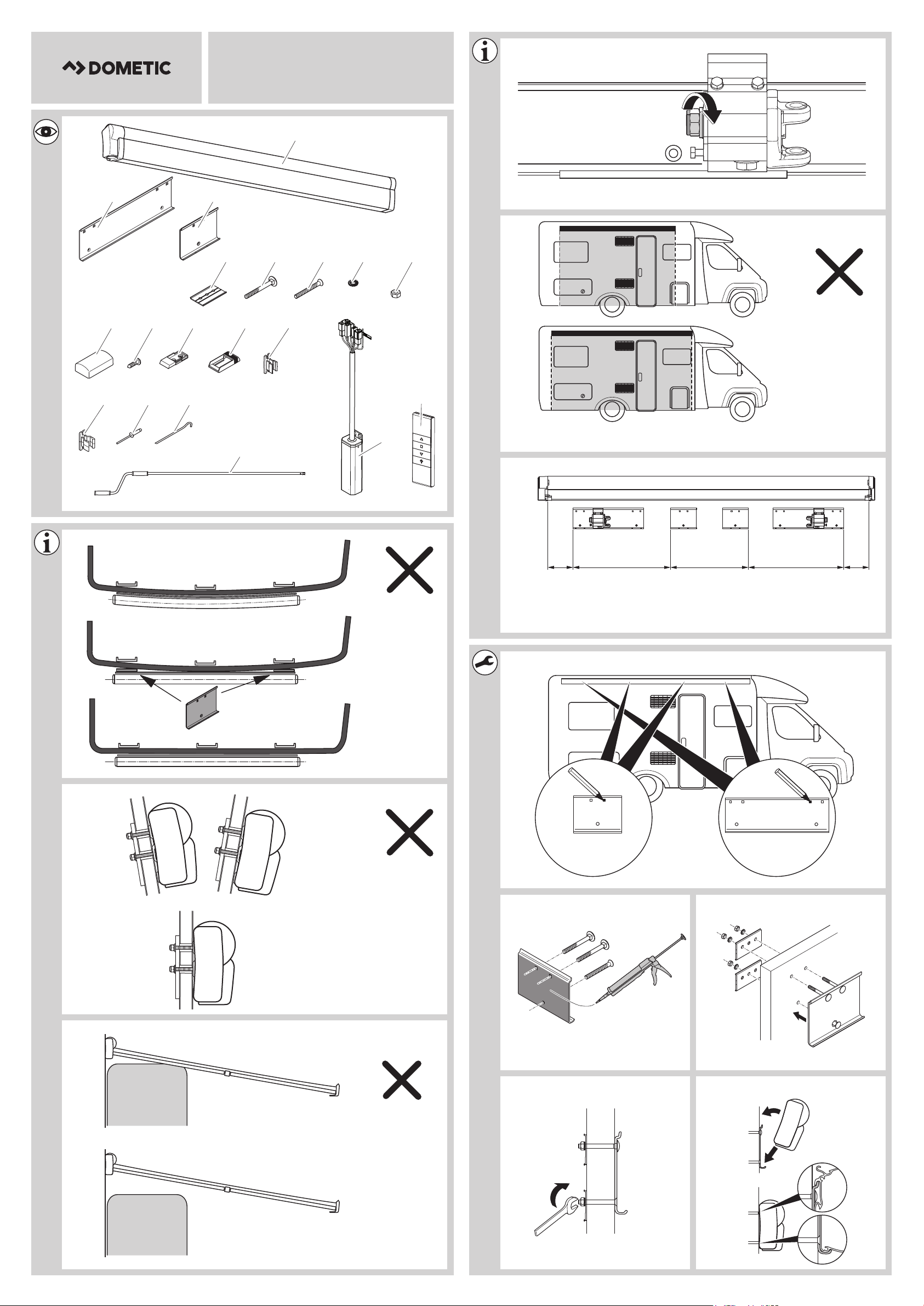
3Scope of delivery
No. in
fig. 1,
page 1
1 1x Awning
2 2x Mounting plate (400 mm)
3 2x Mounting plate (160 mm)
4 12x Counter plate
5 12x Square-head bolt
6 6x Countersunk bolt
7 18x Serrated lock washer
8 18x Hexagon nut
9 12x Cover for the counter plate
10 18x Self-tapping screw
11 2x Mounting bracket (lower section)
12 2x Mounting bracket (upper section)
Awning width
4 m, 4.5 m,
5 m, 5.5 m, 6 m
Description
4

EN
PW3800 Accessories
No. in
fig. 1,
page 1
13 1x Crank bracket (lower section)
14 1x Crank bracket (upper section)
15 4x Rivets
16 4x Pegs
17 1x Crank (only awnings without motor)
18 1x Receiver with connection material
19 1x Remote control with holder
Awning width
4 m, 4.5 m,
5 m, 5.5 m, 6 m
Description
Emergency crank (only awnings with motor)
4Accessories
Available as accessories (not included in the scope of delivery):
Description
TieDown Kit
Straps for anchoring the awning
Dometic Light LK120
LED light kit with remote control for installation on the awning arms
LED LightStrip
LED strip available in different lengths for installation on the underside of the awning
LED Profile
LED lighting available in different lengths for installation on the underside of wall-mounted
awnings
Awning cleaner
Special awning cleaner
Repair Kit
Awning repair patch
Wall switch
If you have questions regarding the accessories, please contact your local service
partner.
5

EN
Intended use PW3800
5 Intended use
The PerfectWall PW3800 awning is suitable for installing on motorhomes or
caravans.
The awning must only be used whilst the vehicle is stationary. Please observe the
operating manual.
6 Installing the awning
6.1 Required installation material
For the installation of the awning, you will need:
• Various tools, e.g. screwdriver
• A suitable flexible adhesive/sealant, e.g. Sikaflex
• A cleaning agent that is recommended for use with the adhesive
• A primer that is recommended for use with the adhesive
• Acid-free silicone
6.2 Notes on the installation position
®
-252
When choosing the installation location, observe the following:
WARNING!
!
A
• Keep a sufficient distance from objects or other vehicles. Once it is
retracted, it should be at least 40 cm away from other objects and
vehicles.
• Ensure the wall of the motorhome can safely take the weight of the
awning before installation. Otherwise, the awning may become
unstable and bend or break.
NOTICE!
• Make sure that the inner screw joints are accessible.
• Only attach the awning to flat and vertical wall surfaces (fig. 2 and
fig. 3, page 1). On curved wall surfaces, the mounting plates need to
be adequately lined under the fastening points.
6

EN
PW3800 Installing the awning
• If there is insufficient space above the door after the awning is
mounted, the door must remain closed when retracting or extending
to avoid the door making contact with the arms or the lead rail.
The required space depends on the design of the door (door width,
swing or sliding door) as well as the set awning angle of inclination
(fig. 4, page 1).
• The cables and cabinets in the interior of the vehicle may not be
damaged by drilling the holes.
NOTE
I
• Ensure the user of the vehicle is aware that the screws on the rear hinge
(fig. 5, page 1) must be tightened up (see operating manual). The
arms must not bear any load. This must be done by the service partner.
6.3 Installing the awning
During installation, observe the following general information:
• The mounting plates are bolted to the vehicle in the area of the rear hinge. In
addition, they are glued with installation adhesive (e.g. Sikaflex
product) to ensure the load is evenly spread and an optimal level of protection
from moisture is maintained.
• Observe the sealant manufacturer's instructions.
• Before installation, check the access to the screw joints. Make sure no cables or
cabinets are damaged when drilling.
• Contact your local service partner if you wish to have an angle of inclination
different to the default setting.
• If you want to use an awning tent with the awning at a later date, ensure that the
vent windows and hatches of the erected tent remain accessible when choosing
the awning size and installation position (fig. 6, page 1).
• Clean the adhesive surfaces on the mounting rails and the wall.
• Prepare the adhesive surfaces with the primer.
• After gluing, wait until the adhesive has set. For further details, please refer to the
information provided by the sealant manufacturer.
• Carefully seal the drill holes to prevent moisture from entering the motorhome
wall.
®
-221 or a similar
7

EN
Installing the awning PW3800
• Do not open the awning or leave it unattended, before the awning has been
fastened to the mounting rails.
• As part of the regular maintenance procedure, the screws on the rear hinge must
be tightened up by a service partner. Ensure the users of the vehicle are aware of
this.
Installing the awning with mounting plates
➤ Select the location of the installation.
In particular, check that there is enough space in the interior to mount the counter
plates at the points where the screws will be.
NOTE
I
➤ Align the mounting plates on the vehicle and mark where the holes are to be
drilled (fig. 8, page 1).
➤ At the marked points, drill holes with a diameter of 6.5 mm from the outside
through the external wall.
➤ Clean the outer sides of the mounting plates and the installation surface on the
vehicle.
Recommended mounting position for each counter plate: fig. 7,
page 1.
➤ Fill the drill holes in the vehicle wall with an acid-free silicone.
➤ Insert the square-head bolts through the relevant holes in the mounting plates
(fig. 9, page 1).
➤ To glue and seal, apply an elastic adhesive, such as Sikaflex
the back of the mounting plates (fig. 9, page 1).
➤ Place all of the mounting plates through the drill holes and fasten them with
counter plate, serrated lock washers and hexagon head bolts (fig. 0, page 1).
➤ Fasten the inner (narrow) mounting plates using a countersunk bolt, counter
plate, serrated lock washer and hexagon nut (fig. a, page 1).
➤ Wait until the glue has set. For further details, please refer to the information
provided by the sealant manufacturer.
➤ Use two people to hook the awning on to the mounting plates (fig. b, page 1).
➤ Insert the cover caps on the counter plates (fig. c, page 2).
➤ Drill two holes with a diameter of 3 mm through the awning and each of the long
mounting plates (fig. d, page 2).
®
-221 for example, to
8

EN
PW3800 Connecting the awning
➤ Drill one hole with a diameter of 3 mm through the awning and each of the short
mounting plates (fig. d, page 2).
➤ Fasten the awning with drill screws (fig. d, page 2).
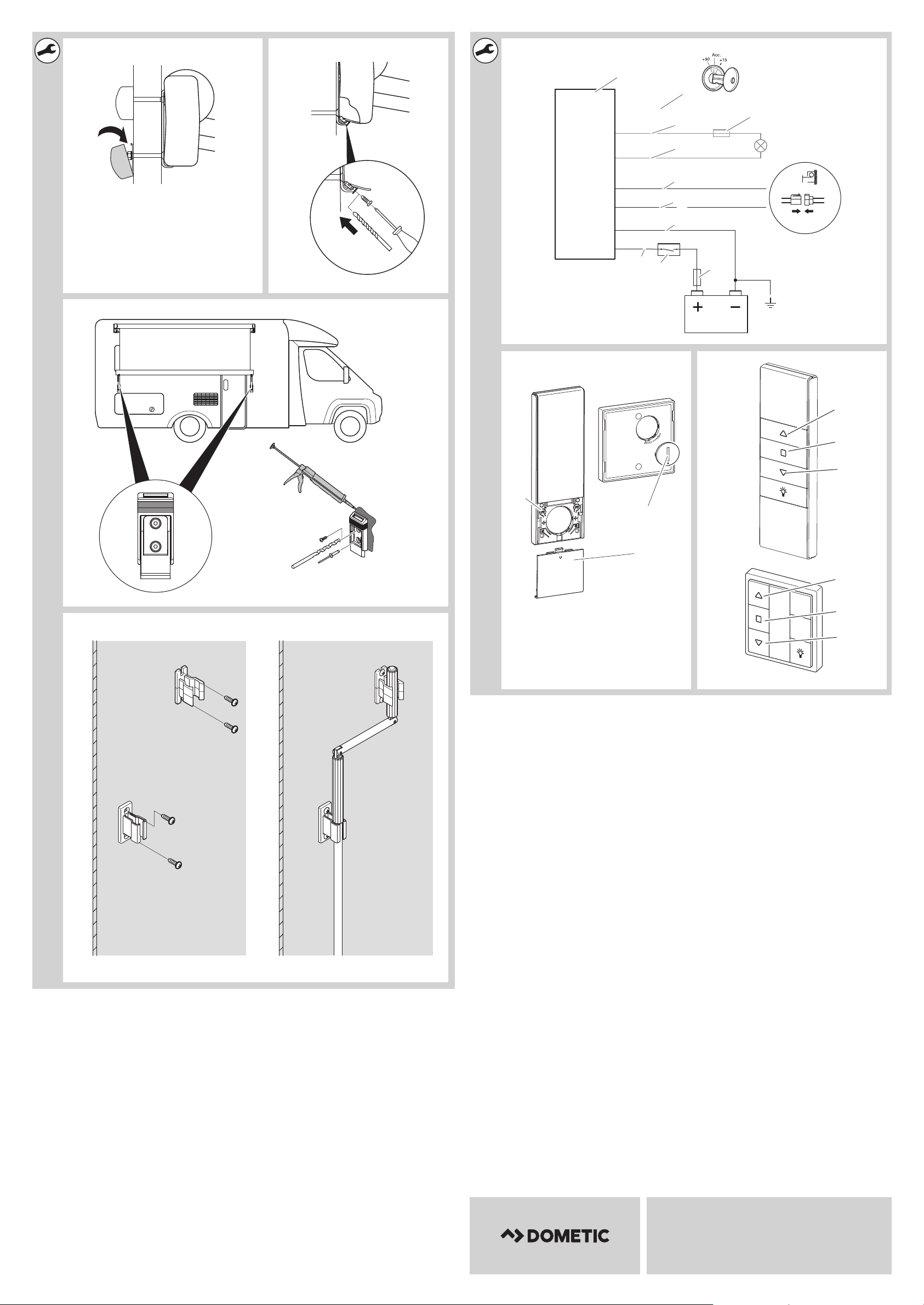
Installing the mounting bracket
The mounting bracket must be installed if the awning is to be attached to the side of
the vehicle when extended.
➤ Select the location of the installation.
➤ Mark where the holes are to be drilled.
➤ At the marked points, drill holes with a diameter of 3 mm from the outside into
the external wall (fig. e, page 2).
➤ Put the upper and lower sections of the mounting bracket together.
➤ Clean the outer sides of the lower section and the installation surface in the
vehicle.
NOTE
I
➤ To glue and seal, apply an elastic adhesive, such as Sikaflex®-221 for example, to
the back of the mounting bracket.
Make sure that no glue gets on to the movable upper section of the
mounting bracket.
➤ Fasten the mounting bracket with drill screws (fig. e, page 2).
or
➤ Rivet the mounting bracket (fig. e, page 2).
Installing the crank bracket
➤ Mount the mounting bracket for the crank at a suitable location inside the vehicle
(fig. f, page 2).
7 Connecting the awning
WARNING!
!
• Disconnect the power supply before starting the assembly.
• Only permit a qualified electrician to connect the awning to the elec-
trical power.
9

EN
Connecting the awning PW3800
NOTICE!
A
There are two options for the electrical connection of the awning:
• Remote control
or
• Wall switch (accessory)
Observe the following installation instructions:
• Fit the supplied main switch and fuse (15 A) to the positive line of the power
supply. The main switch is required to switch off the awning when side walls are
fitted to the awning, for example, or if the vehicle is taken out of service for an
extended period of time (otherwise the standby consumption may drain the
battery).
• Install the receiver on the inside of the vehicle to protect it from moisture.
• Observe the length of the cable between the awning motor and receiver when
choosing a place to install it.
• Do not shorten the antenna cable.
• Connect the ignition (D+ signal) to the orange line of the receiver. This is the only
way to ensure that the awning cannot be opened while driving.
• When installing the supplied plug, use a suitable tool (crimping tool) to ensure
that the connection is secure and durable.
• If you want to connect an awning light (accessory), make sure that its maximum
power consumption is 30 W. When connecting, make sure the polarity is
correct.
• Observe the required cable cross section when connecting to the power supply:
The cables and cabinets in the interior of the vehicle must not be
damaged through drilling the holes.
Cable length Required cable cross section
2 m 1.5 mm²
4 m 1.5 mm²
6 m 2.5 mm²
8 m 2.5 mm²
10

EN
PW3800 Connecting the awning
Legend to fig. g, page 2:
No. Description
1 Receiver
2 3 A fuse for LED awning light (optional)
3 og Orange line for D+ connection
4 rd Red line for LED awning light (optional)
5 bk Black line for LED awning light (optional)
6 bu Blue line for motor connection
7 bn Brown line for motor connection
8 bk Black line for power supply
9 rd Red line for power supply
10 Main switch
11 15 A fuse for main switch
➤ Connect the motor to the receiver in accordance with the applicable electrical
engineering regulations and the circuit diagram (fig. g, page 2).
➤ Find a suitable location inside the motor home, out of direct sunlight, to install the
holder for the remote control and the wall switch (accessory).
Programming the remote control
➤ Place the battery (see fig. h 1, page 2).
➤ Switch on the power supply.
✓ The receiver beeps once briefly.
➤ Press the programming button (fig. h 2, page 2) within 4 seconds.
✓ The receiver beeps once briefly.
➤ Press the programming button (fig. h 2, page 2) again briefly.
✓ The receiver beeps once briefly.
➤ Briefly press the button (fig. i 1, page 2).
✓ The receiver beeps four times briefly.
✓ The awning moves briefly.
11

EN
Connecting the awning PW3800
Programming the wall switch (accessory)
➤ Place the battery (see fig. h 1, page 2).
➤ Switch on the power supply.
✓ The receiver beeps once briefly.
➤ Press the buttons and on the wall switch simultaneously (fig. i 1 and 2,
page 2) within 4 seconds.
✓ The receiver beeps once briefly.
➤ Press the buttons and on the wall switch simultaneously (fig. i 1 and 2,
page 2) again briefly.
✓ The receiver beeps once briefly.
➤ Briefly press the button (fig. i 1, page 2).
✓ The receiver beeps four times briefly.
✓ The awning moves briefly.
Pairing another remote control or wall switch (accessory)
Proceed as follows to pair another remote control:
➤ Press the programming button of the programmed remote control (fig. h 2,
page 2) twice.
✓ The receiver beeps twice briefly.
➤ Press the programming button of the remote control to be paired (fig. h 2,
page 2).
✓ The receiver beeps five times briefly.
✓ The remote controls are now set to one another.
Proceed as follows to pair the wall switch (accessory):
➤ Press the programming button (fig. h 2, page 2) twice.
✓ The receiver beeps twice briefly.
➤ Press the buttons and on the wall switch simultaneously (fig. i 1 and 2,
page 2).
✓ The receiver beeps five times briefly.
✓ The remote control and wall switch are now set to one another.
12

EN
PW3800 Disposal
8Disposal
➤ Place the packaging material in the appropriate recycling waste bins wherever
possible.
If you wish to finally dispose of the product, ask your local recycling centre
or specialist dealer for details about how to do this in accordance with the
M
applicable disposal regulations.
13

DE
Erklärung der Symbole PW3800
WARNUNG!
!
• Diese Anleitung muss vor der Installation, dem Einrichten, dem
Betrieb und der Wartung gelesen und verstanden werden. Dieses
Gerät muss von einer Fachkraft installiert werden. Eine fehlerhafte
Installation kann zu schweren Verletzungen führen. Umbauten am
Gerät können äußerst gefährlich werden und zu schweren
Verletzungen oder zu Geräteschäden führen.
• Diese Anleitung muss beim Gerät verbleiben. Der Besitzer muss sie
aufmerksam lesen.
Inhaltsverzeichnis
1 Erklärung der Symbole . . . . . . . . . . . . . . . . . . . . . . . . . . . . . . . . . . . . . . . . . . 14
2 Wichtige Sicherheits- und Einbauhinweise . . . . . . . . . . . . . . . . . . . . . . . . . .15
3 Lieferumfang . . . . . . . . . . . . . . . . . . . . . . . . . . . . . . . . . . . . . . . . . . . . . . . . . .15
4 Zubehör. . . . . . . . . . . . . . . . . . . . . . . . . . . . . . . . . . . . . . . . . . . . . . . . . . . . . .16
5 Bestimmungsgemäßer Gebrauch . . . . . . . . . . . . . . . . . . . . . . . . . . . . . . . . .17
6 Markise montieren . . . . . . . . . . . . . . . . . . . . . . . . . . . . . . . . . . . . . . . . . . . . .17
7 Markise anschließen . . . . . . . . . . . . . . . . . . . . . . . . . . . . . . . . . . . . . . . . . . . .21
8 Entsorgung . . . . . . . . . . . . . . . . . . . . . . . . . . . . . . . . . . . . . . . . . . . . . . . . . . 24
1 Erklärung der Symbole
WARNUNG!
!
A
I
14
Sicherheitshinweis: Nichtbeachtung kann zu Tod oder schwerer
Verletzung führen.
ACHTUNG!
Nichtbeachtung kann zu Materialschäden führen und die Funktion des
Produktes beeinträchtigen.
HINWEIS
Ergänzende Informationen zur Bedienung des Produktes.

DE
PW3800 Wichtige Sicherheits- und Einbauhinweise
2 Wichtige Sicherheits- und
Einbauhinweise
Beachten Sie die vom Fahrzeughersteller und vom Kfz-Handwerk
vorgeschriebenen Sicherheitshinweise und Auflagen!
Der Hersteller übernimmt in folgenden Fällen keine Haftung für Schäden:
• Montage- oder Anschlussfehler
• Beschädigungen am Produkt durch mechanische Einflüsse
• Veränderungen am Produkt ohne ausdrückliche Genehmigung vom Hersteller
• Verwendung für andere als die in der Anleitung beschriebenen Zwecke
WARNUNG!
!
• Wenn Sie nicht über ausreichende technische Kenntnisse zum
Einbauen von Komponenten in Fahrzeugen verfügen, sollten Sie sich
die Markise von einem Fachmann ans Fahrzeug montieren lassen.
3 Lieferumfang
Nr. in
Abb. 1,
Seite 1
1 1x Markise
2 2x Montageplatte (400 mm)
3 2x Montageplatte (160 mm)
4 12x Gegenplatte
5 12x Vierkantschraube
6 6x Senkschraube
7 18x Fächerscheibe
8 18x Sechskantmutter
9 12x Abdeckung für Gegenplatte
10 18x Bohrschraube
11 2x Wandhalterung (unterer Teil)
12 2x Wandhalterung (oberer Teil)
Markisenbreite
4 m, 4,5 m,
5 m, 5,5 m, 6 m
Bezeichnung
15

DE
Zubehör PW3800
Nr. in
Abb. 1,
Seite 1
13 1x Kurbelhalterung (unterer Teil)
14 1x Kurbelhalterung (oberer Teil)
15 4x Niete
16 4x Hering
17 1x Kurbel (nur Markisen ohne Motor)
18 1x Empfänger mit Anschlussmaterial
19 1x Fernbedienung mit Halter
Markisenbreite
4 m, 4,5 m,
5 m, 5,5 m, 6 m
Bezeichnung
Notkurbel (nur Markisen mit Motor)
4Zubehör
Als Zubehör erhältlich (nicht im Lieferumfang enthalten):
Bezeichnung
TieDown Kit
Gurte zum Abspannen der Markise
Dometic Light LK120
LED-Beleuchtungskit mit Fernbedienung zur Montage an die Markisenarme
LED LightStrip
LED-Streifen in verschiedenen Längen erhältlich zur Montage an der Unterseite der Markise
LED Profile
LED-Beleuchtung in verschiedenen Längen erhältlich zur Montage an der Unterseite der
Wandmarkise
Awning cleaner
Spezieller Markisenreiniger
Repair Kit
Reparaturset für Markisen
Wandschalter
Bei Fragen zu Zubehör wenden Sie sich bitte an Ihren Service-Partner.
16

DE
PW3800 Bestimmungsgemäßer Gebrauch
5 Bestimmungsgemäßer Gebrauch
Die Markise PerfectWall PW3800 ist geeignet zum Anbau an Wohnmobile oder
Wohnwagen.
Die Markise darf nur im Stand benutzt werden. Bitte beachten Sie die
Bedienungsanleitung.
6Markise montieren
6.1 Benötigtes Montagematerial
Für die Montage der Markise benötigen Sie:
• Diverses Werkzeug, z. B. Schraubendreher
• Geeigneter elastischer Kleber/Dichtmittel wie z. B. Sikaflex
• Reiniger, der zur Verwendung mit dem Kleber empfohlen ist
• Primer, der zur Verwendung mit dem Kleber empfohlen ist
• Säurefreies Silikon
6.2 Hinweise zum Montageort
®
-252
Beachten Sie bei der Wahl des Einbauortes Folgendes:
WARNUNG!
!
A
• Halten Sie genügend Abstand zu Gegenständen oder anderen
Fahrzeugen. Nach dem Ausfahren muss ringsum ein Mindestabstand
zu anderen Gegenständen oder Fahrzeugen von 40 cm sein.
• Stellen Sie vor der Installation sicher, dass die Wohnmobilwand die
Markise sicher tragen kann. Sonst kann die Markise instabil werden
und sich verbiegen oder abbrechen.
ACHTUNG!
• Achten Sie darauf, dass die Innenverschraubungen zugänglich sind.
• Montieren Sie die Markise nur an planen und lotrechten Wandflächen
(Abb. 2 und Abb. 3, Seite 1). Bei gewölbten Wandflächen
müssen Sie die Montageplatten an den Befestigungsstellen
ausreichend unterfüttern.
17

DE
Markise montieren PW3800
• Falls nach dem Einbau der Markise kein ausreichender Freiraum über
der Tür verbleibt, muss die Tür während des Ein- oder Ausfahrens
geschlossen bleiben, um einen Kontakt der Tür mit den Armen oder
der Frontleiste zu vermeiden.
Der benötigte Freiraum hängt von der Bauart der Tür (Türbreite,
Schwenk- oder Schiebetür) sowie dem eingestellten Neigungswinkel
der Markise ab (Abb. 4, Seite 1).
• Leitungen und Einbauschränke im Fahrzeuginnenraum dürfen beim
Bohren nicht beschädigt werden.
HINWEIS
I
• Weisen Sie den Benutzer des Fahrzeugs darauf hin, dass die
Schrauben am Schultergelenk (Abb. 5, Seite 1) nachgezogen
werden müssen (siehe Bedienungsanleitung). Die Arme müssen
lastfrei sein. Dies muss durch den Service-Partner erfolgen.
6.3 Markise montieren
Beachten Sie bei der Montage folgenden allgemeinen Hinweise:
• Die Montageplatten werden im Bereich der Schultergelenke am Fahrzeug
verschraubt. Zusätzlich werden sie mit Montagekleber (z. B. Sikaflex
ein vergleichbares Produkt) verklebt, um eine gleichmäßige Lasteinleitung zu
erhalten und einen optimalen Schutz vor Feuchtigkeit zu erreichen.
• Beachten Sie die Hinweise des Dichtmittel-Herstellers.
• Prüfen Sie vor der Montage die Zugänglichkeit der Verschraubungen. Achten
Sie darauf, dass beim Bohren keine Leitungen oder Einbauschränke beschädigt
werden.
• Sollten Sie eine anderen Neigungswinkeleinstellung wünschen als ab Werk
vorgesehen, wenden Sie sich an Ihren Service-Partner.
• Falls Sie später ein Markisenvorzelt mit der Markise verwenden wollen, sollten
Sie bei der Auswahl der Markisengröße und Montageposition darauf achten,
dass Ausstellfenster und Klappen auch bei montiertem Zelt zugänglich bleiben
(Abb. 6, Seite 1).
• Reinigen Sie die Klebeflächen auf den Montageschienen und der Wand.
• Bereiten Sie die Klebeflächen mit dem Primer vor.
• Warten Sie nach dem Kleben, bis der Kleber ausgehärtet ist. Nähere Angaben
entnehmen Sie den Informationen des Dichtmittel-Herstellers.
• Dichten Sie die Bohrungen sorgfältig ab, um Feuchtigkeit in der
Wohnmobilwand zu verhindern.
®
-221 oder
18

DE
PW3800 Markise montieren
• Fahren Sie die Markise nicht aus und lassen Sie sie nicht unbeaufsichtigt, solange
die Markise noch nicht an den Montageschienen fixiert ist.
• Die Schrauben der Schultergelenke müssen im Rahmen einer regelmäßigen
Wartung von einem Service-Partner nachgezogen werden. Weisen Sie die
Benutzer des Fahrzeuges hierauf hin.
Markise mit Montageplatten montieren
➤ Legen Sie den Montageort fest.
Prüfen Sie insbesondere, ob an den Stellen, an denen die Verschraubungen sein
werden, genügend Platz für die Montage der Gegenplatten im Innenraum ist.
HINWEIS
I
➤ Richten Sie die Montageplatten am Fahrzeug aus und zeichnen Sie die
Bohrungen vor (Abb. 8, Seite 1).
➤ Bohren Sie an den angezeichneten Stellen von außen Löcher mit einem
Durchmesser von 6,5 mm durch die Außenwand.
➤ Reinigen Sie die Außenseiten der Montageplatten und die Montagefläche am
Fahrzeug.
➤ Füllen Sie die Bohrungen in der Fahrzeugwand mit säurefreiem Silikon.
Empfohlene Montageposition für jede Gegenplatte: Abb. 7, Seite 1.
➤ Stecken Sie die Vierkantschrauben durch die entsprechenden Löcher der
Montageplatten (Abb. 9, Seite 1).
➤ Tragen Sie zum Kleben und Abdichten auf die Rückseite der Montageplatten
einen elastischen Kleber wie z. B. Sikaflex
➤ Stecken Sie alle Montageplatten durch die Bohrungen und kontern Sie diese mit
Gegenplatte, Fächerscheibe und Sechskantmutter (Abb. 0, Seite 1).
➤ Verschrauben Sie die inneren (schmalen) Montageplatten mit Senkschraube,
Gegenplatte, Fächerscheibe und Sechskantmutter (Abb. a, Seite 1).
➤ Warten Sie, bis der Kleber ausgehärtet ist. Nähere Angaben entnehmen Sie den
Informationen des Dichtmittel-Herstellers.
➤ Hängen Sie die Markise mit zwei Personen in die Montageplatten (Abb. b,
Seite 1).
➤ Stecken Sie die Abdeckkappen auf die Gegenplatten (Abb. c, Seite 2).
➤ Bohren Sie jeweils zwei Löcher mit einem Durchmesser von 3 mm durch die
Markise und die langen Montageplatten (Abb. d, Seite 2).
®
-221 auf (Abb. 9, Seite 1).
19

DE
Markise montieren PW3800
➤ Bohren Sie jeweils ein Loch mit einem Durchmesser von 3 mm durch die Markise
und die schmalen Montageplatten (Abb. d, Seite 2).
➤ Verschrauben Sie die Markise mit Bohrschrauben (Abb. d, Seite 2).
Wandhalterung montieren
Wenn die Markise im ausgefahrenen Zustand an der Fahrzeugwand befestigt
werden soll, muss die Wandhalterung montiert werden.
➤ Legen Sie den Montageort fest.
➤ Zeichnen Sie die Bohrungen vor.
➤ Bohren Sie an den angezeichneten Stellen von außen Löcher mit einem
Durchmesser von 3 mm in die Außenwand (Abb. e, Seite 2).
➤ Stecken Sie das untere und das obere Teil der Wandhalterung zusammen.
➤ Reinigen Sie die Außenseiten des unteren Teils der Wandhalterung und die
Montagefläche am Fahrzeug.
HINWEIS
I
Stellen Sie sicher, dass kein Kleber an das bewegliche obere Teil der
Wandhalterung gerät.
➤ Tragen Sie zum Kleben und Abdichten auf die Rückseite der Wandhalterung
einen elastischen Kleber wie z. B. Sikaflex
➤ Verschrauben Sie die Wandhalterung mit Bohrschrauben (Abb. e, Seite 2).
oder
➤ Vernieten Sie die Wandhalterung (Abb. e, Seite 2).
Kurbelhalterung montieren
➤ Montieren Sie die Wandhalterung für die Kurbel an einer geeigneten Stelle
innerhalb des Fahrzeugs (Abb. f, Seite 2).
®
-221 auf.
20

DE
PW3800 Markise anschließen
7 Markise anschließen
WARNUNG!
!
A
Es gibt zwei Varianten, um die Markise elektrisch anzuschließen:
• Fernbedienung
oder
• Wandschalter (Zubehör)
Beachten Sie folgende Hinweise bei der Montage:
• Installieren Sie den mitgelieferten Hauptschalter und die Sicherung (15 A) in die
positive Leitung der Spannungsversorgung. Der Hauptschalter ist erforderlich,
um die Markise auszuschalten, wenn z. B. ein Markisenvorzelt montiert wird oder
wenn das Fahrzeug für eine längere Zeit außer Betrieb genommen wird
(andernfalls kann der Standby-Verbrauch die Batterie entleeren).
• Installieren Sie den Empfänger im Inneren des Fahrzeug, um ihn vor Feuchtigkeit
zu schützen.
• Beachten Sie bei der Wahl des Montageortes des Empfängers die Kabellänge
zwischen Markisenmotor und Empfänger.
• Kürzen Sie nicht das Antennenkabel.
• Verbinden Sie die Zündung (D+-Signal) mit der orangefarbenen Leitung des
Empfängers. Nur so ist sichergestellt, dass die Markise während der Fahrt nicht
geöffnet werden kann.
• Verwenden Sie zur Montage der mitgelieferten Stecker ein geeignetes
Werkzeug (Krimpzange), um eine sichere und langfristige Verbindung zu
gewährleisten.
• Falls Sie ein Markisenlicht (Zubehör) anschließen möchten, stellen Sie sicher,
dass die maximale Leistungsaufnahme 30 W beträgt. Achten Sie beim Anschluss
auf die richtige Polarität.
• Unterbrechen Sie die Spannungsversorgung, bevor Sie mit der
Montage beginnen.
• Lassen Sie die Markise nur von einer Fachkraft elektrisch anschließen.
ACHTUNG!
Leitungen und Einbauschränke im Fahrzeuginnenraum dürfen beim
Bohren nicht beschädigt werden.
21

DE
Markise anschließen PW3800
• Halten Sie bei der Verbindung mit der Spannungsversorgung den erforderlichen
Kabelquerschnitt ein:
Kabellänge Erforderlicher Kabelquerschnitt
2 m 1,5 mm²
4 m 1,5 mm²
6 m 2,5 mm²
8 m 2,5 mm²
Legende zu Abb. g, Seite 2:
Pos. Bezeichnung
1 Empfänger
2 3-A-Sicherung für LED-Markisenlicht (optional)
3 og orangefarbenen Leitung für D+-Anschluss
4 rd rote Leitung für LED-Markisenlicht (optional)
5 bk schwarze Leitung für LED-Markisenlicht (optional)
6 bu blaue Leitung für Motoranschluss
7 bn braune Leitung für Motoranschluss
8 bk schwarze Leitung für Spannungsversorgung
9 rd rote Leitung für Spannungsversorgung
10 Hauptschalter
11 15-A-Sicherung für Hauptschalter
➤ Schließen Sie den Motor an den Empfänger entsprechend den geltenden
elektrotechnischen Vorschriften und Schaltplan an (Abb. g, Seite 2).
➤ Montieren Sie die Wandhalterung für die Fernbedienung und den Wandschalter
(Zubehör) an einer geeigneten Stelle innerhalb des Wohnmobils, die vor
direktem Sonnenlicht geschützt ist.
22

DE
PW3800 Markise anschließen
Fernbedienung anlernen
➤ Legen Sie die Batterie ein (siehe Abb. h 1, Seite 2).
➤ Schalten Sie die Spannungsversorgung ein.
✓ Der Empfänger piept einmal kurz.
➤ Drücken Sie innerhalb von 4 Sekunden kurz die Programmiertaste der
Fernbedienung (Abb. h 2, Seite 2).
✓ Der Empfänger piept erneut kurz.
➤ Drücken Sie erneut kurz die Programmiertaste der Fernbedienung (Abb. h 2,
Seite 2).
✓ Der Empfänger piept erneut kurz.
➤ Drücken Sie kurz die Taste (Abb. i 1, Seite 2).
✓ Der Empfänger piept viermal kurz.
✓ Die Markise bewegt sich kurz.
Wandschalter (Zubehör) anlernen
➤ Legen Sie die Batterie ein (siehe Abb. h 1, Seite 2).
➤ Schalten Sie die Spannungsversorgung ein.
✓ Der Empfänger piept einmal kurz.
➤ Drücken Sie innerhalb von 4 Sekunden gleichzeitig die Tasten und des
Wandschalters (Abb. i 1 und 2, Seite 2).
✓ Der Empfänger piept erneut kurz.
➤ Drücken Sie erneut gleichzeitig die Tasten und des Wandschalters
(Abb. i 1 und 2, Seite 2).
✓ Der Empfänger piept erneut kurz.
➤ Drücken Sie kurz die Taste (Abb. i 1, Seite 2).
✓ Der Empfänger piept viermal kurz.
✓ Die Markise bewegt sich kurz.
23

DE
Entsorgung PW3800
Weitere Fernbedienung oder Wandschalter (Zubehör) koppeln
Um eine weitere Fernbedienung zu koppeln, gehen Sie wie folgt vor:
➤ Drücken Sie zweimal die Programmiertaste der angelernten Fernbedienung
(Abb. h 2, Seite 2).
✓ Der Empfänger piept zweimal kurz.
➤ Drücken Sie an der zu koppelnden Fernbedienung die Programmiertaste
(Abb. h 2, Seite 2).
✓ Der Empfänger piept fünfmal kurz.
✓ Die Fernbedienungen sind nun aufeinander eingestellt.
Um einen Wandschalter (Zubehör) zu koppeln, gehen Sie wie folgt vor:
➤ Drücken Sie zweimal die Programmiertaste (Abb. h 2, Seite 2).
✓ Der Empfänger piept zweimal kurz.
➤ Drücken Sie am Wandschalter gleichzeitig die Tasten und (Abb. i 1
und 2, Seite 2).
✓ Der Empfänger piept fünfmal kurz.
✓ Fernbedienung und Wandschalter sind nun aufeinander eingestellt.
8Entsorgung
➤ Geben Sie das Verpackungsmaterial möglichst in den entsprechenden
Recycling-Müll.
Wenn Sie das Produkt endgültig außer Betrieb nehmen, informieren Sie
sich bitte beim nächsten Recyclingcenter oder bei Ihrem Fachhändler
M
24
über die zutreffenden Entsorgungsvorschriften.

FR
PW3800 Signification des symboles
AVERTISSEMENT !
!
• Ce manuel doit être lu et compris avant l’installation, la mise en
place, le fonctionnement et la maintenance. Cet appareil doit être
installé par un technicien agréé. Un montage erroné peut entraîner
de graves blessures. Des modifications de l’appareil peuvent s’avérer extrêmement dangereuses et provoquer de graves blessures ou
des dommages de l’appareil.
• Ce manuel doit rester à proximité de l’appareil. Le propriétaire doit
le lire attentivement.
Sommaire
1 Signification des symboles . . . . . . . . . . . . . . . . . . . . . . . . . . . . . . . . . . . . . . 25
2 Consignes de sécurité et instructions de montage importantes . . . . . . . . 26
3 Contenu de la livraison . . . . . . . . . . . . . . . . . . . . . . . . . . . . . . . . . . . . . . . . . 26
4 Accessoires . . . . . . . . . . . . . . . . . . . . . . . . . . . . . . . . . . . . . . . . . . . . . . . . . . 27
5 Usage conforme . . . . . . . . . . . . . . . . . . . . . . . . . . . . . . . . . . . . . . . . . . . . . . 28
6 Montage du store extérieur . . . . . . . . . . . . . . . . . . . . . . . . . . . . . . . . . . . . . 28
7 Raccorder le store extérieur . . . . . . . . . . . . . . . . . . . . . . . . . . . . . . . . . . . . . 32
8 Élimination des déchets . . . . . . . . . . . . . . . . . . . . . . . . . . . . . . . . . . . . . . . . 35
1 Signification des symboles
AVERTISSEMENT !
!
A
I
Consigne de sécurité : le non-respect de ces consignes peut entraîner
la mort ou de graves blessures.
AVIS !
Le non-respect de ces consignes peut entraîner des dommages
matériels et des dysfonctionnements du produit.
REMARQUE
Informations complémentaires sur l'utilisation du produit.
25

FR
Consignes de sécurité et instructions de montage importantes PW3800
2 Consignes de sécurité et instructions de
montage importantes
Respectez les consignes de sécurité et autres prescriptions imposées par
le fabricant du véhicule et par les professionnels de l’automobile.
Le fabricant décline toute responsabilité pour des dommages dans les cas suivants :
• des défauts de montage ou de raccordement
• des influences mécaniques ayant endommagé le matériel
• des modifications apportées au produit sans autorisation explicite de la part du
fabricant
• une utilisation différente de celle décrite dans la notice
AVERTISSEMENT !
!
• Si vos connaissances techniques en matière d’installation d’éléments
dans un véhicule sont insuffisantes, nous vous recommandons de faire
installer l’auvent par un spécialiste.
3 Contenu de la livraison
Pos. dans
fig. 1,
page 1
1 1x Store extérieur
2 2x Plaque de montage (400 mm)
3 2x Plaque de montage (160 mm)
4 12x Plaque de maintien
5 12x Boulon à tête carrée
6 6x Vis à tête conique
7 18x Rondelle en éventail
8 18x Écrou hexagonal
9 12x Cache pour plaque de maintien
10 18x Vis perceuse
11 2x Support de montage (partie inférieure)
Largeur du store extérieur
4 m, 4,5 m
5 m, 5,5 m, 6 m
Description
26

FR
PW3800 Accessoires
Pos. dans
fig. 1,
page 1
12 2x Support de montage (partie supérieure)
13 1x Support de manivelle (partie inférieure)
14 1x Support de manivelle (partie supérieure)
15 4x Rivet
16 4x Sardine
17 1x Manivelle (uniquement les stores extérieurs
18 1x Récepteur avec matériel de raccordement
19 1x Télécommande avec support
Largeur du store extérieur
4 m, 4,5 m
5 m, 5,5 m, 6 m
Description
sans moteur)
Manivelle de secours (uniquement les
stores extérieurs avec moteur)
4Accessoires
Disponibles en accessoires (non compris dans la livraison) :
Description
Kit d’arrimage
Sangle permettant de tendre le store extérieur
Dometic Light LK120
Kit d’éclairage DEL avec télécommande, à monter sur les bras du store extérieur
LED LightStrip
Bande de LED disponible en différentes longueurs pour une installation sur le dessous du
store extérieur
Profil de LED
Éclairage à LED disponible en différentes longueurs pour une installation sur le dessous des
stores extérieurs à montage mural
Nettoyant pour stores extérieurs
Nettoyant spécial pour stores extérieurs
27

FR
Usage conforme PW3800
Description
Nécessaire de réparation
Patch de réparation pour stores extérieurs
Commutateur mural
En cas de questions concernant les accessoires, veuillez vous adresser à votre
partenaire de service après-vente.
5Usage conforme
Le store extérieur PerfectWall PW3800 est conçu pour être installé sur des campingcars ou des caravanes.
Le store extérieur doit être utilisé à l’arrêt uniquement. Veuillez respecter les
consignes du manuel d’utilisation.
6 Montage du store extérieur
6.1 Matériel de montage nécessaire
Pour le montage du store, vous avez besoin des éléments suivants :
• Divers outils, p. ex. tournevis
• Colle élastique/produit d’étanchéité adapté comme p. ex. Sikaflex
• Détergent recommandé pour l’utilisation avec la colle
• Couche d’apprêt recommandée pour l’utilisation avec la colle
• Silicone sans acide
®
-252
6.2 Consignes relatives au lieu de montage
Pour le choix de l’emplacement de montage, tenez compte des remarques
suivantes :
AVERTISSEMENT !
!
• Respectez une distance suffisante par rapport aux objets ou aux autres
véhicules. Une fois le store extérieur déplié, la distance minimale avec
les autres objets ou véhicules doit être de 40 cm.
28
 Loading...