

Dometic PERFECTVIEW VS400N Installation And Operating Manual
O
K
C
4
C3
C
2
C
1
ENDEFRESPTITNLDASV
NOFIRUPLSKCSHU
DRIVING SUPPORT
PERFECTVIEW
VS400N
Video s plitter
Installation and Operating Manual . . . . . . 9
Videos plitter
Montage- und Bedienungsanleitung . . . 19
Splitter vidéo
Instructions de montage
et de service . . . . . . . . . . . . . . . . . . . . . . . 29
Divisor de vídeo
Instrucciones de montaje y de uso . . . . . 39
Divisor de vídeo
Instruções de montagem e manual de
instruções . . . . . . . . . . . . . . . . . . . . . . . . . 49
Video s plitter
Istruzioni di montaggio e d’uso . . . . . . . .59
Videos plitter
Montagehandleiding en
gebruiksaanwijzing. . . . . . . . . . . . . . . . . . 69
Videos plitter
Monterings- og betjeningsvejledning. . . 78
Video s plitter
Monterings- och bruksanvisning . . . . . . . 87
Videos plitter
Monterings- og bruksanvisning . . . . . . . .96
Videojakaja
Asennus- ja käyttöohje. . . . . . . . . . . . . . 105
Разветвитель видеосигнала
Инструкция по монтажу
и эксплуатации. . . . . . . . . . . . . . . . . . . . .114
Rozdzielacz sygnału wideo
Instrukcja montażu i obsługi . . . . . . . . . 124
Rozdeľovač video signálu
Návod na montáž a uvedenie
do prevádzky . . . . . . . . . . . . . . . . . . . . . 134
Videos plitter
Návod k montáži a obsluze . . . . . . . . . . 144
Videó- splitter
Szerelési és használati útmutató . . . . . . 154

VS400N
1
2
4
5
2
3
1
1
C
C3
2
2
4
C
K
O
C1
3
3
OK
C4
C3 C2
C1
4
3
1
5
2
3
VS400N
4
VS400N
1
2
3
4
9
6
8
5
7
10
11
12
4
5
VS400N
5
6
7
6

VS400N
2.
1.
1.
8
9
0
2
1
3
4
5
6
7
7
1
2
3
a
VS400N
8

VS400N Explanation of symbols
EN
Please read this instruction manual carefully before installati on and first use, and store
it in a safe place. If you pass on the product to another person, hand over this instruction manual along with it.
Table of contents
1 Explanation of symbols. . . . . . . . . . . . . . . . . . . . . . . . . . . . . . . . . . . . . . . . . . . . . . . . . . . . . . . 9
2 Safety and installation instructions . . . . . . . . . . . . . . . . . . . . . . . . . . . . . . . . . . . . . . . . . . . . . 10
3 Scope of delivery . . . . . . . . . . . . . . . . . . . . . . . . . . . . . . . . . . . . . . . . . . . . . . . . . . . . . . . . . . 12
4 Intended use . . . . . . . . . . . . . . . . . . . . . . . . . . . . . . . . . . . . . . . . . . . . . . . . . . . . . . . . . . . . . . 12
5 Technical description . . . . . . . . . . . . . . . . . . . . . . . . . . . . . . . . . . . . . . . . . . . . . . . . . . . . . . . 12
6 Installing the video splitter . . . . . . . . . . . . . . . . . . . . . . . . . . . . . . . . . . . . . . . . . . . . . . . . . . . 13
7 Connecting electrical power to the video splitter. . . . . . . . . . . . . . . . . . . . . . . . . . . . . . . . . 15
8 Operation . . . . . . . . . . . . . . . . . . . . . . . . . . . . . . . . . . . . . . . . . . . . . . . . . . . . . . . . . . . . . . . . 17
9 Troubleshooting . . . . . . . . . . . . . . . . . . . . . . . . . . . . . . . . . . . . . . . . . . . . . . . . . . . . . . . . . . . 17
10 Warranty . . . . . . . . . . . . . . . . . . . . . . . . . . . . . . . . . . . . . . . . . . . . . . . . . . . . . . . . . . . . . . . . . 17
11 Disposal. . . . . . . . . . . . . . . . . . . . . . . . . . . . . . . . . . . . . . . . . . . . . . . . . . . . . . . . . . . . . . . . . . 18
12 Technical data . . . . . . . . . . . . . . . . . . . . . . . . . . . . . . . . . . . . . . . . . . . . . . . . . . . . . . . . . . . . . 18
1 Explanation of symbols
WARN ING !
!
!
Safety instruction: Failure to observe this instruction can cause death or serious
injury.
CAUTION!
Safety instruction: Failure to observe this instruction can lead to injury.
A
I
NOTICE!
Failure to observe this instruction can cause material damage and impair the function
of the product.
NOTE
Supplementary information for operating the product.
9

Safety and installation instructions VS400N
EN
2 Safety and installation instructions
The manufacturer accepts no liability for damage in the following cases:
• Damage to the product resulting from mechanical influences and inco rrect connection voltage
• Alterations to the product without express permission from the manufacturer
•Use for purposes other than those described in the operating manual
Please observe the prescribed safety instructions and stipulations from the vehicle
manufacturer and service workshops.
WARN ING !
Inadequate supply cable connections could result in short circuits, which could have as
!
a consequence that:
•
Cable fires occur
•
The airbag is triggered
•
Electronic control devices are damaged
•
Electric functions fail (indicators, brake light, horn, ignition, lights)
NOTICE!
To prevent the risk of short circuits, always disconnect the negative terminal of the
A
vehicle's electrical system before working on it.
If the vehicle has an additional battery, its negative terminal should also be disconnected.
Please observe the following instructions:
• When working on the following cables, only use insulated cable lugs, plugs and flat push-on
recepta cles:
– 30 (direct supply from positive battery terminal)
–15 (connected positive terminal, behind the battery)
– 31 (return line from the battery, earth)
– L (indicator lights left)
– R (indicator lights right)
Do not use terminal strips.
• Use a crimping tool t o connect the cables.
• When connecting to cable 31 (earth), screw the cable
– to the vehicle's earth bolt with a cable lug and a gear disc or
– to the sheet-metal bodywork with a cable lug and a self-tapping screw.
Ensure that there is a good earth connection.
10

VS400N Safety and installation instructions
EN
If you disconnect the negative terminal of the battery, all data stored in the volatile memories will
be lost.
• The following data must be set again, depending on the vehicle equipment options:
–Radio code
– Vehicle clock
–Timer
– On-board computer
– Seat position
You can find instructions for making these settings in the appropriate operating instructions.
Observe the following installation instructions:
CAUTION!
• Secure the parts installed in the vehicle in such a way that they cannot become loose
!
A
Observe the following instructions when working with electrical parts:
A
under any circumstances (sudden braking, accidents) and cause injuries to the
occupants of the vehicle.
• Secure any parts of the system covered by the bodywork in such a manner that they
cannot be come loose or damage other parts and cables or impair vehicle functions
(steering, pedals, etc).
• Always follow the safety instructions of the vehicle manufacturer.
Some work (e.g. on retention systems such as the AIRBAG etc.) may only be
performed by qualified specialists.
NOTICE!
• To prevent damage when drilling, make sure there is sufficient space on the other
side for the drill head to come out.
• Deburr all drill holes and treat them with a rust-protection agent.
NOTICE!
• When testing the voltage in electrical cables, only use a diode test lamp or a
voltmeter.
Test lamps with an illuminant take up voltages which are too high and which can
damage the vehicle's electronic system.
• When making electrical connections, ensure that:
– they are not kinked or twisted
– they do not rub on edges
– they are not laid in sharp edged ducts without protection.
• Insulate all connections.
• Secure the cables against mechanical wear with cable binders or insulating tape,
for example to existing cables.
11

Scope of delivery VS400N
EN
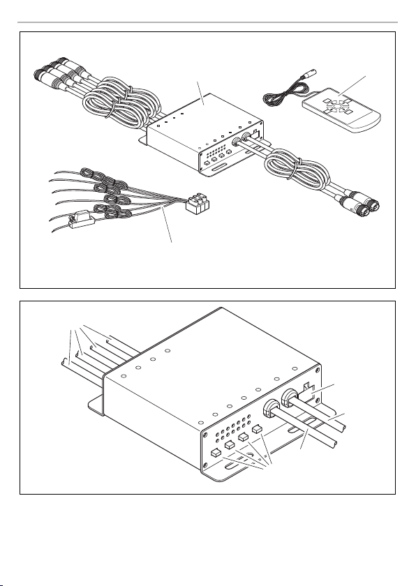
3Scope of delivery
No. in
fig. 1, page 3
11Control unit –
2 1 Operating unit 9600017666
3 1 Cable set 9600017665
Quantity Description Ref. no.
4Intended use
The VS 400N video splitter is used for displaying up to four camera signals on a monitor at the same
time.
5 Technical description
5.1 Function description
The system is comprised of a control unit and an operating unit. The control unit must be installed
in the vehicle and protected from moisture. The operating unit is affixed in the vehicle interior.
5.2 Connections and control elements
The control unit features the following connections and control elements:
No. in
fig. 2, page 3
1Camera connection for max. 4 cameras
2 Connection socket for the cable set
3 Connection for operating unit
4 Connection for monitor
5 On/off switch for the camera inputs
Explanation
12

VS400N Installing the video splitter
EN
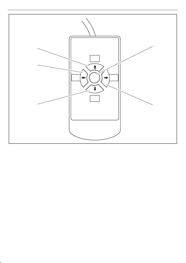
The operating unit features the following control elements:
No. in
fig. 3, page 4
1 C1 button
2 C2 button
3 C3 button
4 C4 button
5 OK button
Explanation
Activates camera C1
Activates camera C2
Activates camera C3
Activates camera C4
Activates the corresponding selected split screen
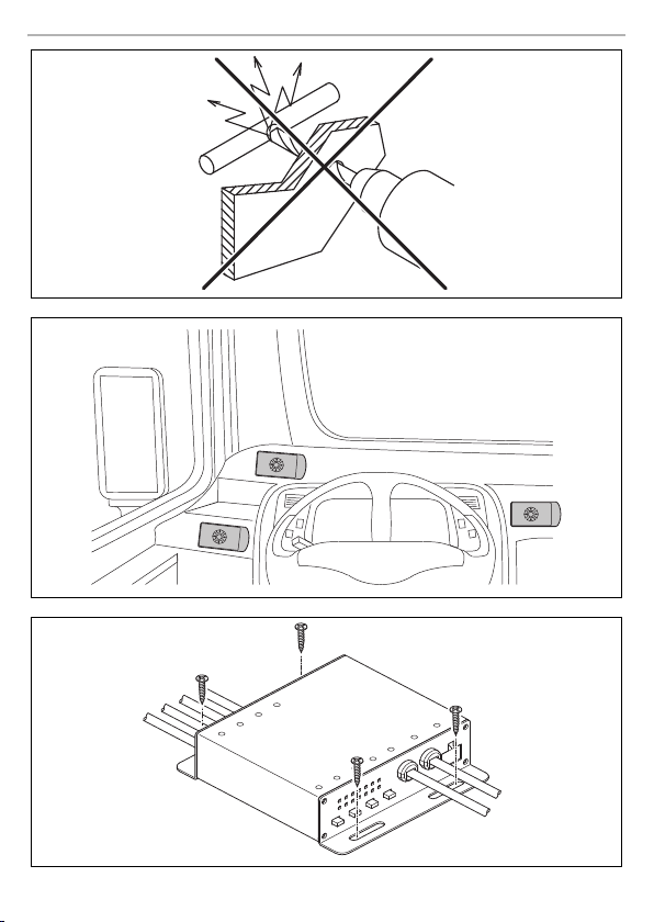
6 Installing the video splitter
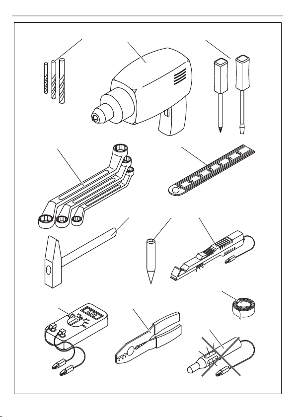
6.1 Tools required
For installation and assembly, you will need the following tools:
See fig. 4, page 5
• Drill head set (1)
• Drill (2)
• Screwdriver (3)
• Set of ring or open-ended spanners (4)
• Measuring ruler (5)
•Hammer (6)
•Center punch (7)
13

Installing the video splitter VS400N
EN
To establish and test the electrical connection, the following tools are required:
See fig. 4, page 5
•Diode test lamp (8) or voltmeter (9)
• Crimping tool (10)
•Insulating tape (11)
• If applicable, cable bushing sleeves
To secure the control unit and the cables, you may require additional screws and cable ties.
CAUTION!
!
Note the following instructions during installation:
• The installation location must be protected from moisture and be inside the vehicle.
• The installation location should be flat.
• Before drilling each hole, ensure there is sufficient space on the other side for the drill head to
To perform the installation, proceed as follows:
➤ Attach the control unit an d the operating unit to their respective in stallation location provision-
➤ Install the reversing video system if you have not already done so.
➤ Start up the reversing video system.
6.2 Installing the operating unit
I
Select the location of the modules so that they cannot injure the passengers in the vehicle under any circumstances (e.g. sudden braking, traffic accidents).
emerge (fig. 5, page 6).
ally.
If transmission of the camera image is stable, you can carry out the final installation of the control unit and operating unit.
NOTE
Make sure the adhesive surfaces (surface an d bottom of the unit) are clean, dry and free
of grease.
Proceed as follows:
➤ Glue the Velcro strip to the bottom of the operating unit.
➤ Glue the matching Velcro strip to a suitable position in the vehicle (fig. 6, page 6).
➤ Affix the operating unit.
14

VS400N Connecting electrical power to the video splitter
EN
6.3 Installing the control unit
Proceed as follows:
➤ Hold the control unit at the chosen installation location and mark the four points for the drill
holes.
➤ Drill the holes, with a diameter of 3.5 mm, at each of the markings.
➤ Screw the control unit in place using the 4 mm self-tapping screws (fig. 7, page 6).
7 Connecting electrical power to the video splitter
7.1 General notes on laying cables
NOTE
I
Therefore, please observe the following instructions:
• Wherever possible, always lay cables inside the vehicle, as they are better protec ted there than
• To prevent damage to the cables when laying them, ensure that they are always far enough
• Screw on the plug connections for the connecting cables to protect them against water pene-
•When laying the cables, make sure that:
• Protect every through-hole made in the bodywork against water penetration by suitable meas-
• As far as possible, use existing through-holes to lay the c onnection cables, or other
suitable options such as bodywork edges, ventilation grilles or dummy panels. If no
openings are available, you must drill holes for the respective cables. Check beforehand that there is sufficient space on the other side for the drill head to emerge.
• Cables and cable connections that are not properly installed will regularly cause
malfunctions or damage to components. Co rrect installation of cables and connections is the prerequisite for lasting and trouble-free operation of the retrofitted components.
outside.
If you do need to lay a cable outside the vehicle, ensure that it is well fastened (use additional
cable ties, insulating tape, etc.).
away from hot or moving vehicle components (exhaust pipes, drive shafts, light systems, fans,
heaters, etc.).
tration (fig. 8, page 7).
– they are not kinked or twisted,
– they do not rub on edges,
– they are not laid in sharp edged ducts without protection (fig. 9, page 7).
ures, e.g. by using a cable with a sealant and by spraying the cable and the cable sleeve with
sealant.
I
NOTE
Only start sealing through-holes when you have completed all installation work on the
camera and have determined the required connection cable lengths.
15

Connecting electrical power to the video splitter VS400N
EN
7.2 Connecting the control unit
➤ Connect this connection (fig. 2 3, page 3) to the operating unit.
➤ Connect this connection (fig. 2 4, page 3) to the monitor.
➤ Connect the camera connections (fig. 2 1, page 3) to the cameras.
➤ Continue with the setup as described in the following chapter (chapter “Connecting the cable
set” on page 16).
7.3 Connecting the cable set
The cable set features the following connections:
No. in
fig. 0, page 7
1 Plug for the control unit, 6-pin
2 Control input for reversing light (camera 1), green
3 Control input for camera 2, white
4 Control input for camera 3, blue
5 Control input for camera 4, brown
6 Earth connection –, black
7 12 V connection +, red
See fig. 0, page 7
➤ Connect the plug on the cable set (1) to the socket of the control unit (fig. 2 2, page 3).
➤ Connect the green cable (2) to the positive wire (+) of the reversing light (camera 1).
➤ Connect the white cable (3) to the control signal for camera 2.
➤ Connect the blue cable (4) to the control signal for camera 3.
➤ Connect the brown cable (5) to the control signal for camera 4.
➤ Connect the black cable (6) to the earth wire (–) or to earth (bodywork).
➤ Connect the red cable (7) to the positive wire (+) of the vehicle.
Explanation
7.4 Switching camera inputs on and off
With the on/off switches (fig. 2 4 , p age 3) on the con tro l uni t, t he c amer a in put s are swi tch ed on
and off. When the camera input is switched off, it is skipped and an empty screen is avoided.
16

VS400N Operation
EN
8 Operation
8.1 Remote control
Activating cameras
See fig. 3, page 4
➤ Press the C1 (1) button to activate camera 1.
➤ Press the C2 (2) button to activate camera 2.
➤ Press the C3 (3) button to activate camera 3.
➤ Press the C4 (4) button to activate camera 4.
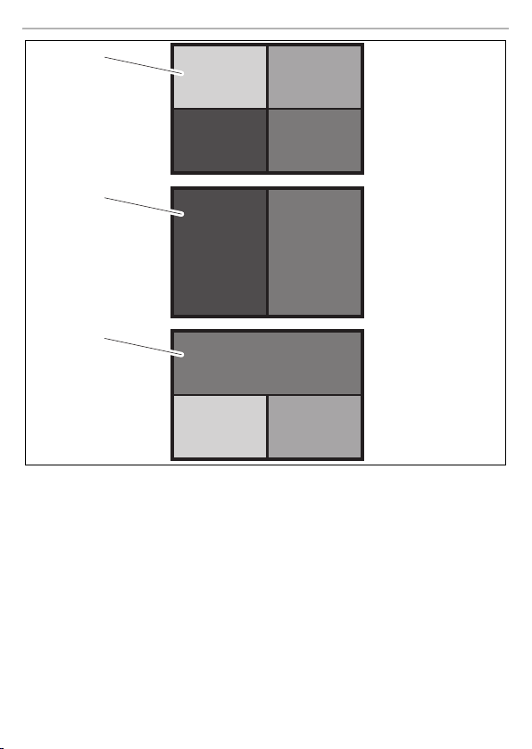
Activating the split screen
➤ Press OK (fig. 3 5, page 4) to activate the selected split scree n (fig. a 1–3,page8).
9 Troubleshooting
Fault Suggested remedy
The monitors remains black. Ensure that the mo nitor is switc hed on.
Ensure that the control unit and the monitor share a power connection.
10 Warranty
The statutory warranty period applies. If the product is defective, please contact the
manu factu rer's b ranch i n your c ountry (see th e back o f the in struct ion ma nual fo r the ad dresse s) or
your retailer.
For repair and warranty processing, please include the following documents when you send in the
device:
• A copy of the receipt with purchasing date
• A reason for the claim or description of the fault
17

Disposal VS400N
EN
11 Disposal
➤ Place the packaging material in the appropriate recycling waste bins wherever possible.
If you wish to finally dispose of the product, ask your local recycling centre or specialist
dealer for details about how to do this in accordance with the applicable disposal
M
regulations.
12 Technical data
VS 400N
Reference number: 9600013958
Video standard: PAL/NTSC
Frame rate: PAL 50 frames/s
Video input: 1.0 V
Video output: 1.0 V
Resolution: PAL: 720 x 576 pixels
Operating temperature: –20 °C to +65 °C
Operating voltage: 12 – 32 Vg
Current consumption: 200 mA
Protection class: IP50
Dimensions W x H x D: 127 x 33 x 113 mm
Weig ht: 20 0 g
Certifications: ECE R10
NTSC 60 frames/s
, 75 Ω
P-P
, 75 Ω
P-P
NTSC: 720 x 480 pixels
ISO 16750
18

VS400N Erklärung der Symbole
DE
Bitte lesen Sie diese Anleitung vor Einbau und Inbetriebnahme sorgfältig durch und
bewahren Sie sie auf. Geben Sie sie im Falle einer Weitergabe des Produktes an den
Nutzer weiter.
Inhaltsverzeichnis
1 Erklärung der Symbole . . . . . . . . . . . . . . . . . . . . . . . . . . . . . . . . . . . . . . . . . . . . . . . . . . . . . . 19
2 Sicherheits- und Einbauhinweise. . . . . . . . . . . . . . . . . . . . . . . . . . . . . . . . . . . . . . . . . . . . . .20
3 Lieferumfang . . . . . . . . . . . . . . . . . . . . . . . . . . . . . . . . . . . . . . . . . . . . . . . . . . . . . . . . . . . . . .22
4 Bestimmungsgemäßer Gebrauch . . . . . . . . . . . . . . . . . . . . . . . . . . . . . . . . . . . . . . . . . . . . .22
5 Technische Beschreibung . . . . . . . . . . . . . . . . . . . . . . . . . . . . . . . . . . . . . . . . . . . . . . . . . . . 22
6 Videosplitter montieren . . . . . . . . . . . . . . . . . . . . . . . . . . . . . . . . . . . . . . . . . . . . . . . . . . . . .23
7 Videosplitter elektrisch anschließen . . . . . . . . . . . . . . . . . . . . . . . . . . . . . . . . . . . . . . . . . . .25
8 Bedienung. . . . . . . . . . . . . . . . . . . . . . . . . . . . . . . . . . . . . . . . . . . . . . . . . . . . . . . . . . . . . . . . 27
9 Störungsbeseitigung . . . . . . . . . . . . . . . . . . . . . . . . . . . . . . . . . . . . . . . . . . . . . . . . . . . . . . . 27
10 Gewährleistung . . . . . . . . . . . . . . . . . . . . . . . . . . . . . . . . . . . . . . . . . . . . . . . . . . . . . . . . . . .27
11 Entsorgung . . . . . . . . . . . . . . . . . . . . . . . . . . . . . . . . . . . . . . . . . . . . . . . . . . . . . . . . . . . . . . .28
12 Technische Daten . . . . . . . . . . . . . . . . . . . . . . . . . . . . . . . . . . . . . . . . . . . . . . . . . . . . . . . . . . 28
1 Erklärung der Symbole
WARN UNG !
!
!
Sicherheitshinweis: Nichtbeachtung kann zu Tod oder schwerer Verletzung führen.
VORSIC HT!
Sicherheitshinweis: Nichtbeachtung kann zu Verletzungen führen.
A
I
ACHTUNG!
Nichtbeachtung kann zu Materialschäden führen und die Funktion des Produktes
beeinträchtigen.
HINWEIS
Ergänzende Informationen zur Bedienung des Produktes.
19

Sicherheits- und Einbauhinweise VS400N
DE
2 Sicherheits- und Einbauhinweise
Der Hersteller übernimmt in folgenden Fällen keine Haftung für Schäden:
• Beschädigungen am Produkt durch mechanische Einflüsse und falsche Anschlussspannung
• Veränderungen am Produkt ohne ausdrückliche Genehmigung vom Hersteller
• Verwendung für andere als die in der Anleitung beschriebenen Zwecke
Beachten Sie die vom Fahrzeughersteller und vom Kfz-Handwerk vorgeschriebenen
Sicherheitshinweise und Auflagen!
WARN UNG !
Unzureichende Leitungsverbindungen können zur Folge haben, dass durch Kurzschluss
!
•
Kabelbrände entstehen,
•
der Airbag ausgelöst wird,
•
elektronische Steuerungseinrichtungen beschädigt werden,
•
elektrische Funktionen ausfallen (Blinker, Bremslicht, Hupe, Zündung, Licht).
ACHTUNG!
Klemmen Sie wegen der Kurzschlussgefahr vor Arbeiten an der Fahr zeugelektrik immer
A
den Minuspol ab.
Bei Fahrzeugen mit Zusatzbatterie müssen Sie an dieser ebenfalls den Minuspol
abklemmen.
Beachten Sie deshalb folgende Hinweise:
• Verwenden Sie bei Arbeiten an den folgenden Leitungen nur isolierte Kabelschuhe, Stecker
und Flachsteckhülsen:
– 30 (Eingang von Batterie Plus direkt)
– 15 (Geschaltetes Plus, hinter Batterie)
– 31 (Rückleitung ab Batterie, Masse)
– L (Blinkerleuchten links)
– R (Blinkerleuchten rechts)
Verwend en Si e keine Lüsterklemmen.
• Verwenden Sie eine Krimpzange zum Verbinden der Kabel.
• Schrauben Sie das Kabel bei Anschlüssen an Leitung 31 (Masse)
– mit Kabelschuh und Zahnscheibe an eine fahrzeugeigene Masseschraube oder
– mit Kabelschuh und Blechschraube an das Karosserieblech.
Achten Sie auf eine gute Masseübertragung!
20

VS400N Sicherheits- und Einbauhinweise
DE
Beim Abklemmen des Minuspols der Batterie verlieren alle flüchtigen Speicher der Komfortelektronik ihre gespeicherten Daten.
• Folgende Daten müssen Sie je nach Fahrzeugausstattung neu einstellen:
–Radiocode
–Fahrzeuguhr
– Zeitschaltuhr
– Bordcomputer
– Sitzposition
Hinweise zur Einstellung finden Sie in der jeweiligen Bedienungsanleitung.
Beachten Sie folgende Hinweise bei der Montag e:
VORSIC HT!
• Befestigen Sie die im Fahrzeug montierten Teile so, dass sie sich unter keinen
!
A
Beachten Sie folgende Hinweise bei der Arbeit an elektrischen Teilen:
A
Umständen (scharfes Abbremsen, Verkehrsunfall) lösen und zu Verletzungen der
Fahrzeuginsassen führen können.
• Befestigen Sie verdeckt unter Verkleidungen anzubringende Teile des Systems so,
dass sie sich nicht lösen oder andere Teile und Leitungen beschädigen und keine
Fahrzeugfunktionen (Lenkung, Pedale usw.) beeinträchtigen können.
• Beachten Sie immer die Sicherheitshinweise des Fahrzeugherstellers.
Einige Arbeiten (z. B. an Rückhaltesystemen wie Airbag usw.) dürfen nur von
geschultem Fachpersonal durchgeführt werden.
ACHTUNG!
• Achten Sie beim Bohren auf ausreichenden Freiraum für den Bohreraustritt, um
Schäden zu vermeiden.
• Entgraten Sie jede Bohrung und behandeln Sie diese mit Rostschutzmittel.
ACHTUNG!
• Benutzen Sie zum Prüfen der Spannung in elektrischen Leitungen nur eine Diodenprüflampe oder ein Voltmeter.
Prüflampen mit einem Leuchtkörper nehmen zu hohe Ströme auf, wodurch die
Fahrzeugelektronik beschädigt werden kann.
• Beachten Sie beim Verlegen der elektrischen Anschlüsse, dass diese
– nicht geknickt oder verdreht werden,
– nicht an Kanten scheuern,
– nicht ohne Schutz durch scharfkantige Durchführungen verlegt werden.
• Isolieren Sie alle Verbindungen und Anschlüsse.
• Sichern Sie die Kabel gegen mechanische Beanspruchung durch Kabelbinder oder
Isolierband, z. B. an vorhandenen Leitungen.
21

Lieferumfang VS400N
DE
3Lieferumfang
Nr. in
Abb. 1,
Seite 3
11Steuergerät –
2 1 Bedieneinheit 9600017666
3 1 Kabelsatz 9600017665
Menge Bezeichnung Artikel-Nr.
4 Bestimmungsgemäßer Gebrauch
Der Videosplitter VS 400N dient zur gleichzeitigen Darstellung von bis zu vier Kamerasignalen auf
einem Monitor.
5 Technische Beschreibung
5.1 Funktionsbeschreibung
Das System besteht aus einem Steuergerät und einer Bedieneinheit. Das Steuergerät muss feuchtigkeitsgeschützt im Fahrzeug montiert werden. Die Bedieneinheit wird im Fahrzeuginnenraum
befestigt.
5.2 Bedienelemente und Anschlüsse
Am Steuergerät finden Sie folgende Anschlüsse und Bedienelemente:
Nr. in
Abb. 2,
Seite 3
1 Kamera-Anschluss für max. 4 Kameras
2 Anschlussbuchse für den Kabelsatz
3 Bedieneinheit-Anschluss
4 Monitor-Anschluss
5 Ein-/Ausschalter für die Kameraeingänge
Erklärung
22

VS400N Videosplitter montieren
DE
An der Bedieneinheit finden Sie folgende Bedienelemente:
Nr. in
Abb. 3,
Seite 4
1Taste C1
2Taste C2
3Taste C3
4Taste C4
5Taste OK
Erklärung
Aktiviert die Kamera C1
Aktiviert die Kamera C2
Aktiviert die Kamera C3
Aktiviert die Kamera C4
Aktiviert die jeweils gewählte Bildteilung
6 Videosplitter montieren
6.1 Benötigtes Werkzeug
Für Einbau und Montage benötigen Sie folgende Werkzeuge:
Siehe Abb. 4, Seite 5
•Satz Bohrer (1)
•Bohrmaschine (2)
• Schraubendreher (3)
• Satz Ring- oder Maulschlüssel (4)
•Maßstab (5)
•Hammer (6)
•Körner (7)
23

Videosplitter montieren VS400N
DE
Für den elektrischen Anschluss und seine Überprüfung benötigen Sie folgende Hilfsmittel:
Siehe Abb. 4, Seite 5
• Diodenprüflampe (8) oder Voltmeter (9)
•Krimpzange (10)
• Isolierband (11)
• Ggf. Kabeldurchführu ngstüllen
Zur Befestigung des Steuergeräts und der Kabel benötigen Sie ggf. noch weitere Schrauben
und Kabelbinder.
VORSIC HT!
!
Beachten Sie folgende Hinweise bei der Montag e:
• Der Montageort muss feuchtigkeitsgeschützt sein und sich innerhalb des Fahrzeugs befinden.
• Der Montageort sollte eben sein.
• Kontrollieren Sie vor jedem Bohren, ob ausreichender Freiraum für den Bohreraustritt
Gehen Sie bei der Montage wie folgt vor:
➤ Befestigen Sie das Steuergerät und die Bedieneinheit provisorisch jeweils am geplanten
➤ Montieren Sie ggf. das Rückfahrvideosystem.
➤ Nehmen Sie das Rückfahrvideosystem in Betrieb.
Wählen Sie den Platz der Module so aus, dass unter keinen Umständen (z. B. durch
scharfes Abbremsen, Verkehrsunfall) Fahrzeuginsassen verletzt werden können.
vorhanden ist (Abb. 5, Seite 6).
Montageort.
Wenn das Kamerabild stabil übertragen wird, können Sie das Steuergerät und die Bedieneinheit endgültig montieren.
6.2 Bedieneinheit montieren
HINWEIS
I
Achten Sie dabei darauf, dass die Klebeflächen (Untergrund und Unterseite) sauber,
trocken und fettfrei sind.
Gehen Sie wie folgt vor:
➤ Kleben Sie das Klettband unter die Bedieneinheit.
➤ Kleben Sie das Gegenstück des Klettbandes an eine geeignete Position im Fahrzeug
(Abb. 6, Seite 6).
➤ Befestigen Sie die Bedieneinheit.
24

VS400N Videosplitter elektrisch anschließen
DE
6.3 Steuergerät montieren
Gehen Sie wie folgt vor:
➤ Halten Sie das Steuergerät an den gewählten Montageort und markieren Sie die vier
Bohrpunkte.
➤ Bohren Sie an den zuvor angezeichneten Punkten jeweils ein Loch von Ø 3,5 mm.
➤ Schrauben Sie das Steuergerät mit 4 mm Blechschrauben an (Abb. 7, Seite 6).
7 Videosplitter elektrisch anschließen
7.1 Allgemeine Hinweise zur Kabelverlegung
HINWEIS
I
Beachten Sie deshalb folgende Hinweise:
• Verlegen Sie die Kabel nach Möglichkeit immer im Fahrzeuginneren, denn do rt sind sie besser
• Um Beschädigungen am Kabel zu vermeiden, halten Sie beim Verlegen der Kabel immer
• Verschrauben Sie die Steckverbindungen der Verbindungskabel zum Schutz gegen das
• Beachten Sie beim Verlegen der Kabel, dass diese
• Schützen Sie jeden Durchbruch an der Außenhaut durch geeignete Maßnahmen gegen
• Verwenden Sie für die Durchführung der Anschlusskabel nach Möglichkeit
Originaldurchführungen oder andere Durchführungsmöglichkeiten, z. B.
Verkleidungskanten, Lüftungsgitter oder Blindschalter. Wenn keine Durchführungen vorhanden sind, müssen Sie für die jeweiligen Kabel entsprechende
Löcher bohren. Schauen Sie vorher nach, ob ausreichender Freiraum für den
Bohreraustritt vorhanden ist.
• Nicht fachgerechte Kabelverlegungen und Kabelverbindungen führen immer
wieder zu Fehlfunktionen oder Beschädigung en von Bauteilen. Eine korrekte
Kabelverlegung bzw. Kabelverbindung ist die Grundvoraussetzung für eine
dauerhafte und fehlerfreie Funktion der nachgerüsteten Komponenten.
geschützt als außen am Fahrzeug.
Wenn Sie die Kabel trotzdem außerhalb des Fahrzeuges verlegen, achten Sie auf eine sichere
Befestigung (durch zusätzliche Kabelbinder, Isolierband usw.).
ausreichend Abstand zu heißen und sich bewegenden Fahrzeugteilen (Auspuffrohre,
Antriebswellen, Lichtmaschine, Lüfter, Heizung usw.).
Eindringen von Wasser (Abb. 8, Seite 7).
– nicht stark geknickt oder verdreht werden,
–nicht an Kanten scheuern,
– nicht ohne Schutz durch scharfkantige Durchführungen verlegt werden (Abb. 9, Seite 7).
Wassereinbruch, z. B. durch Einsetzen des Kabels mit Dichtungsmasse und durch Abspritzen
des Kabels und der Durchführungstülle mit Dichtungsmasse.
25

Videosplitter elektrisch anschließen VS400N
DE
HINWEIS
I
Beginnen Sie mit dem Abdichten der Durchbrüche erst, nachdem alle Einstella rbeiten
an der Kamera abgeschlossen sind und die benötigten Längen der Anschlusskabel
festliegen.
7.2 Steuergerät anschließen
➤ Verbinden Sie diesen Anschluss (Abb. 2 3, Seite 3) mit der Bedieneinheit.
➤ Verbinden Sie diesen Anschluss (Abb. 2 4, Seite 3) mit dem Monitor.
➤ Verbinden Sie die Kameraanschlüsse (Abb. 2 1, Seite 3) mit den Kameras.
➤ Fahren Sie mit der Einrichtung fort, wie es im folgenden Kapitel beschrieben ist (Kapitel
„Kabelsatz anschließen“ auf Seite 26).
7.3 Kabelsatz anschließen
Am Kabelsatz finden Sie folgende Anschlüsse:
Nr. in
Abb. 0,
Seite 7
1 Stecker für das Steuergerät, 6-polig
2 Steuereingang Rückfahrscheinwerfer (Kamera 1), grün
3Steuereingang Kamera 2, weiß
4Steuereingang Kamera 3, blau
5Steuereingang Kamera 4, braun
6 Masseanschluss –, schwarz
7 12 V Anschluss +, rot
Siehe Abb. 0, Seite 7
➤ Verbinden Sie den Stecker am Kabelsatz (1) mit der Buchse des Steuergerätes (Abb. 2 2,
Seite 3).
➤ Schließen Sie das grüne Kabel (2) an die Plusleitung (+) des Rückfahrscheinwerfers an
(Kamera 1).
➤ Schließen Sie das weiße Kabel (3) an das Steuersignal für Kamera 2 an.
➤ Schließen Sie das blaue Kabel (4) an das Steuersignal für Kamera 3 an.
➤ Schließen Sie das braune Kabel (5) an das Steuersignal für Kamera 4 an.
➤ Schließen Sie das schwarze Kabel (6) an die Masseleitung (–) oder an Masse (Karosserie) an.
➤ Schließen Sie das rote Kabel (7) an die Plusleitung (+) des Fahrzeugs an.
Erklärung
26

VS400N Bedienung
DE
7.4 Kameraeingänge ein- und ausschalten
Mit den Ein-/Ausschaltern (Abb. 2 4, Seite 3) am Steuergerät werden die Kameraeingänge
ein- und ausgeschaltet. Bei einem ausgeschalteten Kameraeingang wird dieser übersp rungen und
ein leerer Bildschirm wird vermieden.
8 Bedienung
8.1 Fernbedienung
Kameras aktivieren
Siehe Abb. 3, Seite 4
➤ Drücken Sie die Taste C1 (1), um die Kamera 1 zu aktivieren.
➤ Drücken Sie die Taste C2 (2), um die Kamera 2 zu aktivieren.
➤ Drücken Sie die Taste C3 (3), um die Kamera 3 zu aktivieren.
➤ Drücken Sie die Taste C4 (4), um die Kamera 4 zu aktivieren.
Bildteilung aktivieren
➤ Drücken Sie OK (Abb. 3 5, Se ite 4), um die gewählte Bildteilung (Abb. a 1 – 3, Seite 8) zu
aktivieren.
9 Störungsbeseitigung
Störung Lösungsvorschlag
Der Monitor bleibt schwarz. Stellen Sie sicher, dass der Monitor eingeschaltet ist.
Stellen Sie sicher, dass das Steuergerät und der Monitor
elektrisch miteinander verbunden sind.
10 Gewährleistung
Es gilt die gesetzliche Gewährleistungsfrist. Sollte das Produkt defekt sein, wenden Sie sich bitte
an die Niederlassung des Herstellers in Ihrem Land (Adressen siehe Rückseite der Anleitung) oder
an Ihren Fachhändler.
Zur Reparatur- bzw. Gewährleistungsbearbeitung müssen Sie folgende Unterlagen mitschicken:
• eine Kopie der Rechnung mit Kaufdatum,
• einen Reklamationsgrund oder eine Fehlerbeschreibung.
27

Entsorgung VS400N
DE
11 Entsorgung
➤ Geben Sie das Verpackungsmaterial möglichst in den entsprechenden Recycling-Müll.
Wenn Sie das Produkt endgültig außer Betrieb nehmen, informieren Sie sich bitte beim
nächsten Recyclingcenter oder bei Ihrem Fachhändler über die zutreffenden
M
Entsorgungsvorschriften.
12 Technische Daten
VS400N
Artikelnummer: 9600013958
Video Standard: PAL/NTSC
Bildrate: PAL 50 Bilde r/s
Video Eingang: 1,0 V
Video Ausgang: 1,0 V
Auflösung: PAL: 720 x 576 Pixel
Betriebstemperatur: –20 °C bis +65 °C
Betriebsspannung: 12 – 32 Vg
Stromverbrauch: 200 mA
Schutzklasse: IP50
Abmessungen B x H x T: 127 x 33 x 113 mm
Gewicht: 200 g
Zulassungen: ECE R10
NTSC 60 Bilder/s
, 75 Ω
P-P
, 75 Ω
P-P
NTSC: 720 x 480 Pixel
ISO 1 6750
28

VS400N Signification des symboles
FR
Veuillez lire attentivement cette notice avant le montage et la mise en service. Veuillez
ensuite la conserver. En cas de passer le produit, veuillez le transmettre au nouvel
acquéreur.
Sommaire
1 Signification des symboles . . . . . . . . . . . . . . . . . . . . . . . . . . . . . . . . . . . . . . . . . . . . . . . . . . .29
2 Consignes de sécurité et instructions de montage. . . . . . . . . . . . . . . . . . . . . . . . . . . . . . . .30
3 Contenu de la livraison . . . . . . . . . . . . . . . . . . . . . . . . . . . . . . . . . . . . . . . . . . . . . . . . . . . . . . 32
4 Usage conforme . . . . . . . . . . . . . . . . . . . . . . . . . . . . . . . . . . . . . . . . . . . . . . . . . . . . . . . . . . . 32
5 Description technique . . . . . . . . . . . . . . . . . . . . . . . . . . . . . . . . . . . . . . . . . . . . . . . . . . . . . .32
6 Montage splitter vidéo . . . . . . . . . . . . . . . . . . . . . . . . . . . . . . . . . . . . . . . . . . . . . . . . . . . . . . 33
7 Raccordement électrique du splitter vidéo . . . . . . . . . . . . . . . . . . . . . . . . . . . . . . . . . . . . . .35
8 Utilisation. . . . . . . . . . . . . . . . . . . . . . . . . . . . . . . . . . . . . . . . . . . . . . . . . . . . . . . . . . . . . . . . .37
9 Guide de dépannage . . . . . . . . . . . . . . . . . . . . . . . . . . . . . . . . . . . . . . . . . . . . . . . . . . . . . . .37
10 Garantie. . . . . . . . . . . . . . . . . . . . . . . . . . . . . . . . . . . . . . . . . . . . . . . . . . . . . . . . . . . . . . . . . . 37
11 Élimination des déchets . . . . . . . . . . . . . . . . . . . . . . . . . . . . . . . . . . . . . . . . . . . . . . . . . . . . .38
12 Caractéristiques techniques. . . . . . . . . . . . . . . . . . . . . . . . . . . . . . . . . . . . . . . . . . . . . . . . . .38
1Signification des symboles
AVERTISSEMENT !
!
!
Consigne de sécurité : le non-respect de ces consignes peut entraîner la mort ou de
graves blessures.
ATTENTION !
Consigne de sécurité : le non-respect de ces consignes peut entraîner des bles-
sures.
A
I
AVIS !
Le non-respect de ces consignes peut entraîner des dommages matériels et des
dysfonctionnements du produit.
REMARQUE
Informations complémentaires sur l'utilisation du produit.
29

Consignes de sécurité et instructions de montage VS400N
FR
2 Consignes de sécurité et instructions de montage
Le fabricant décline toute responsabilité pour des dommages dans les cas suivants :
• des sollicitations mécaniques et une tension de raccordement incorrecte ayant endommagé le
matériel
• des modifications apportées au produit sans autorisation explicite de la part du fabricant
• une utilisation différente de celle décrite dans la notice
Respectez les consignes de sécurité et autres prescriptions imposées par le fabricant
du véhicule et par les professionnels de l'automobile !
AVERTISSEMENT !
Tout branchement électrique inadéquat peut entraîner un court-circuit causant
!
•
la combustion de câbles,
•
le déclenchement de l'airbag,
•
l’endommagement des dispositifs électroniques de commande,
•
la défaillance des fonctions électriques (c lignotants, feux-stop, klaxon, allumage,
éclairage).
AVIS !
Débranchez toujours la borne négative avant de procéder à des travaux sur les éléments
A
électriques du véhicule afin d’éviter tout risque de court-circuit.
Sur les véhicules équipés d’une batterie supplémentaire, vous devez également
débrancher le pôle négatif de cette dernière.
Veuillez donc respecter les consignes suivantes :
• Pour tous les travaux sur les lignes électriques suivantes, n’utilisez que des cosses de câble,
fiches et alvéoles pour contacts plats isolés :
– 30 (entrée directe pôle positif de la batterie)
–15 (pôle positif connecté, derrière la batterie)
– 31 (ligne de retour à partir de la batterie, masse)
– L (clignotants gauches)
– R (clignotants droits)
N’utilisez pas de dominos.
• Utilisez une pince à sertir pour relier les câbles.
• Pour les raccordements à la ligne électrique 31 (masse), vissez le câble
– à une vis de masse du véhicule, avec une cosse et une rondelle crantée, ou bien
– à la carrosserie, avec une cosse et une vis à tôle.
Veillez à une bonne transmission de la masse !
30
 Loading...