

Dometic PerfectView Switch 300 Operating Manual
Switch300
Right RCA DIN R L B
(CA3) (Monitor) (Mirror S/W)
SWITCH300
Left
(CA2)
Back
(CA1)
Left View S/W
Right Blink
Monitor
Trigger
Left Blink
11 – 32 V
GND
ACT-S/W
Right View S/W
B+
Back Gear
Back View S/W
ENDEFRESPTITNLDASV
NO
FIRUPLSKCS
HU
Control Box
Operating manual. . . . . . . . . . . . . . . . . . . . 7
DRIVING SUPPORT
PERFECTVIEW
Разветвительная коробка
Инструкция по эксплуатации . . . . . . . . .101
Rozgałęźnik
Instrukcja obsługi . . . . . . . . . . . . . . . . . . .110
Spínací box
Návod na obsluhu . . . . . . . . . . . . . . . . . .118
Spínací skříňka
Návod k obsluze. . . . . . . . . . . . . . . . . . . 126
Kapcsolódoboz
Használati utasítás . . . . . . . . . . . . . . . . . 134
Schaltbox
Bedienungsanleitung . . . . . . . . . . . . . . . . 15
Boîte de commande
Notice d’utilisation . . . . . . . . . . . . . . . . . . 23
Caja de distribución
Instrucciones de uso . . . . . . . . . . . . . . . . .32
Caixa de distribuição
Manual de instruções . . . . . . . . . . . . . . . . 41
Scatola di comando
Istruzioni per l’uso. . . . . . . . . . . . . . . . . . . 50
Schakelbox
Gebruiksaanwijzing . . . . . . . . . . . . . . . . .60
Kontrolboks
Betjeningsvejledning . . . . . . . . . . . . . . . . 69
Kopplingsbox
Bruksanvisning . . . . . . . . . . . . . . . . . . . . . 77
Koblingsboks
Bruksanvisning . . . . . . . . . . . . . . . . . . . . . 85
Kytkinrasia
Käyttöohje . . . . . . . . . . . . . . . . . . . . . . . . . 93
SWITCH300
1
45 6
23
1
2
2
SWITCH300
Right RCA DIN R L B
(CA3) (Monitor) (Mirror S/W)
Left
(CA2)
Back
(CA1)
Left View S/W
Right Blink
Monitor
Trigger
Left Blink
GND
Right View S/W
B+
Back Gear
Back View S/W
SWITCH300
11 – 32 V
ACT-S/W
1
2
4
3
5
3
3
SWITCH300
4
Right RCA DIN R L B
(CA3) (Monitor) (Mirror S/W)
SWITCH300
Left
(CA2)
Back
(CA1)
Left View S/W
Right Blink
Monitor
Trigger
Left Blink
11 – 32 V
GND
ACT-S/W
Right View S/W
B+
Back Gear
Back View S/W
1
2
5
12
3
Right RCA DIN R L B
(CA3) (Monitor) (Mirror S/W)
SWITCH300
Left
(CA2)
Back
(CA1)
Left View S/W
Right Blink
Monitor
Trigger
Left Blink
11 – 32 V
GND
ACT-S/W
Right View S/W
B+
Back Gear
Back View S/W
3
4
5
6
4
SWITCH300
gr ws sw rt/sw
2
34a
1
Right RCA DIN R L B
(CA3) (Monitor) (Mirror S/W)
Left
(CA2)
Back
(CA1)
Left View S/W
Right Blink
Monitor
Trigger
Left Blink
11 – 32 V
GND
Right View S/W
B+
Back Gear
Back View S/W
4b
rt
gn br ge or
bl
SWITCH300
ACT-S/W
6
EN
DE
FR
ES
PT
IT
NL
DA
SV
NO
bl br ge gn gr or rt sw ws
Blue Brown Yellow Green Grey Orange Red Black White
BlauBraunGelbGrünGrauOrangeRot SchwarzWeiss
Bleu Marron Jaune Vert Gris Orange Rouge Noir Blanc
Azul Marrón Amarillo Verde Gris Naranja Rojo Negro Blanco
Azul Castanho Ama-
Blu Marrone Giallo Verde Grigio Aranci-
relo
Verde Cin-
zento
Cor de
laranja
Ver-
Preto Branco
melho
Rosso Nero Bianco
one
Blauw Bruin Geel Groen Grijs Oranje Rood Zwart Wit
Blå Brun Gul Grøn Grå Orange Rød Sort Hvid
Blå Brun Gul Grön Grå Orange Röd Svart Vit
Blå Brun Gul Grønn Grå Oransje Rød Svart Hvit
Sini-
FI
nen
Ruskea Keltai-
nen
Vihreä Harmaa Oranssi Punai-
nen
Musta Valkoi-
nen
5

SWITCH300
bl br ge gn gr or rt sw ws
Синий Корич-
RU
Nie-
PL
bieski
невый
Brązowy Żółty Zielony Szary Poma-
Желтый Зеленый Серый Ора-
нжевый
rańc-
Красный Черный Белый
Czer-
Czarny Biały
wony
zowy
Modrá Hnedá Žltá Zelená Sivá Oran-
SK
Červená Čierna Biela
žová
Modrá Hněda Žlutá Zelená Šedá Oran-
CS
Červená Černá Bílá
žová
Kék Barna Sárga Zöld Szürke Narancs Piros Fekete Fehér
HU
6

SWITCH300 Notes on using the manual
EN
Please read this instruction manual carefully before first use, and store it in a safe place.
If you pass on the product to another person, hand over this instruction manual along
with it.
Contents
1 Notes on using the manual. . . . . . . . . . . . . . . . . . . . . . . . . . . . . . . . . . . . . . . . . . . . . . . . . . . .7
2 Safety and installation instructions . . . . . . . . . . . . . . . . . . . . . . . . . . . . . . . . . . . . . . . . . . . . . .8
3 Scope of delivery . . . . . . . . . . . . . . . . . . . . . . . . . . . . . . . . . . . . . . . . . . . . . . . . . . . . . . . . . . . 9
4 Proper usage. . . . . . . . . . . . . . . . . . . . . . . . . . . . . . . . . . . . . . . . . . . . . . . . . . . . . . . . . . . . . . 10
5 Technical description . . . . . . . . . . . . . . . . . . . . . . . . . . . . . . . . . . . . . . . . . . . . . . . . . . . . . . . 10
6 Connecting the control box. . . . . . . . . . . . . . . . . . . . . . . . . . . . . . . . . . . . . . . . . . . . . . . . . . 11
7 Using the control box . . . . . . . . . . . . . . . . . . . . . . . . . . . . . . . . . . . . . . . . . . . . . . . . . . . . . . . 13
8 Guarantee . . . . . . . . . . . . . . . . . . . . . . . . . . . . . . . . . . . . . . . . . . . . . . . . . . . . . . . . . . . . . . . . 14
9 Disposal. . . . . . . . . . . . . . . . . . . . . . . . . . . . . . . . . . . . . . . . . . . . . . . . . . . . . . . . . . . . . . . . . . 14
10 Technical data. . . . . . . . . . . . . . . . . . . . . . . . . . . . . . . . . . . . . . . . . . . . . . . . . . . . . . . . . . . . . 14
1 Notes on using the manual
NOTICE!
A
I
Failure to observe this instruction can cause material damage and impair the function
of the product.
NOTE
Supplementary information for operating the product.
7

Safety and installation instructions SWITCH300
EN
2 Safety and installation instructions
The manufacturer accepts no liability for damage in the following cases:
• Damage to the product resulting from mechanical influences and excess voltage
• Alterations to the product without express permission from the manufacturer
• Use for purposes other than those described in the operating manual
NOTICE!
A
A
To prevent short circuits, always disconnect the negative terminal of the electrical
system before working on the vehicle.
If the vehicle has an additional battery, its negative terminal should also be
disconnected.
NOTICE!
Inadequate supply cable connections could result in short circuits with the
consequence that:
• cable fires occur
• the airbag is triggered
• electronic control devices are damaged
• electric functions fail (indicators, brake light, horn, ignition, lights)
NOTICE!
A
Please observe the following instructions:
• When working on the following supply lines, only use insulated cable lugs, plugs and tab
sleeves.
– 30 (direct supply from positive battery terminal)
–15 (connected positive terminal, behind the battery)
– 31 (return cable from the battery, earth)
– 58 (reversing light)
Do not use terminal strips.
• Use a crimping tool to connect the cables.
For permanent connections, you can solder the cable ends together and then insulate them.
• When connecting to supply cable 31 (earth), screw the cable
– to the vehicle's earth bolt with a cable lug and a gear disc or
– to the sheet-metal bodywork with a cable lug and a self-tapping screw.
Ensure that all lines are connected correctly. The control line may never be connected
to earth; doing so can damage the device. Make especially sure to insulate the bare
end of the control line when it is not in use and thus not connected.
Ensure that there is a good earth connection.
8

SWITCH300 Scope of delivery
EN
When the negative terminal of the battery is disconnected, all data stored in the volatile memory
will be lost.
• The following data must be set again, depending on the vehicle equipment options:
–radio code
– vehicle clock
–timer
– on-board computer
– seat position
You can find instructions for making these settings in the appropriate operating instructions.
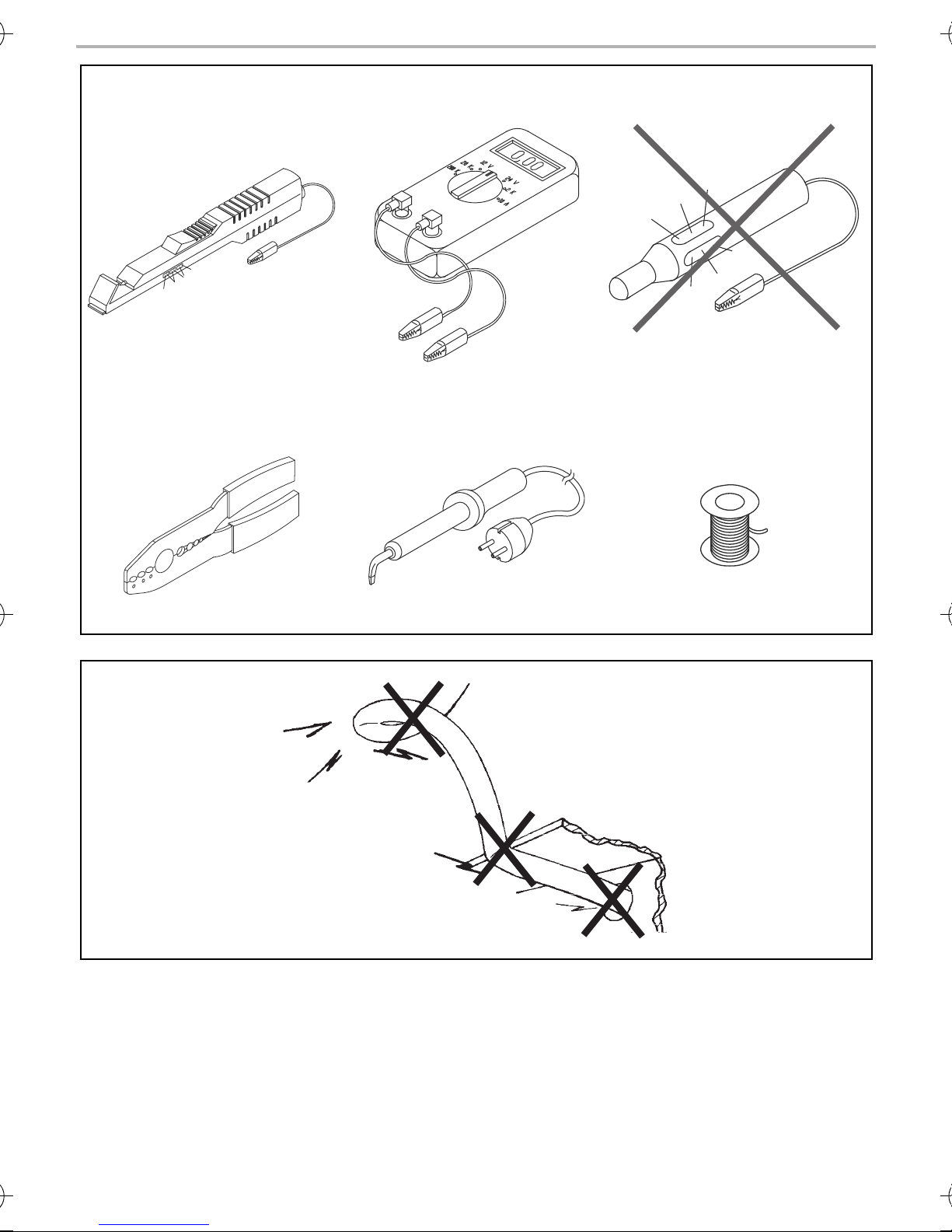
Observe the following instructions when working with electrical parts:
• When testing the voltage in electrical cables, only use a diode test lamp (fig. 1 1, page 2) or a
voltmeter (fig. 1 2, page 2).
Test lamps with an illuminant (fig. 1 3, page 2) consume voltages which are too high and can
damage the vehicle's electronic system.
• When making electrical connections, ensure that
– they are not kinked or twisted
– they do not rub on edges
– they are not laid in sharp edged ducts without protection (fig. 2, page 2).
• Insulate all connections.
• Secure the cables against mechanical wear with cable binders or insulating tape, for example
to existing cables.
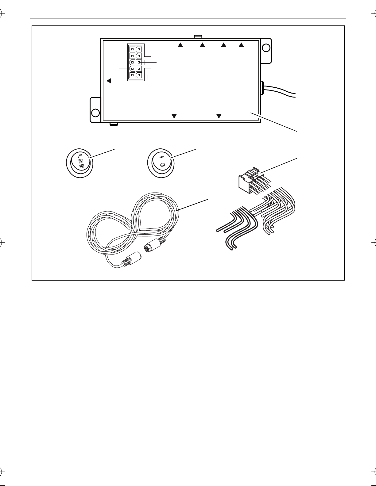
3Scope of delivery
No. in
fig. 3, page 3
1 1 control box 9600000067
2 1 connection cable for vehicle electrics
3 1 three-stage switch for activating the
4 1 two-stage switch for activating manual
5 1 connecting cables for control box–
Quan-
tity
Description Ref. no.
camera manually
operation
RV-502-M/M
monitor
– 1 installation material
9

Proper usage SWITCH300
EN
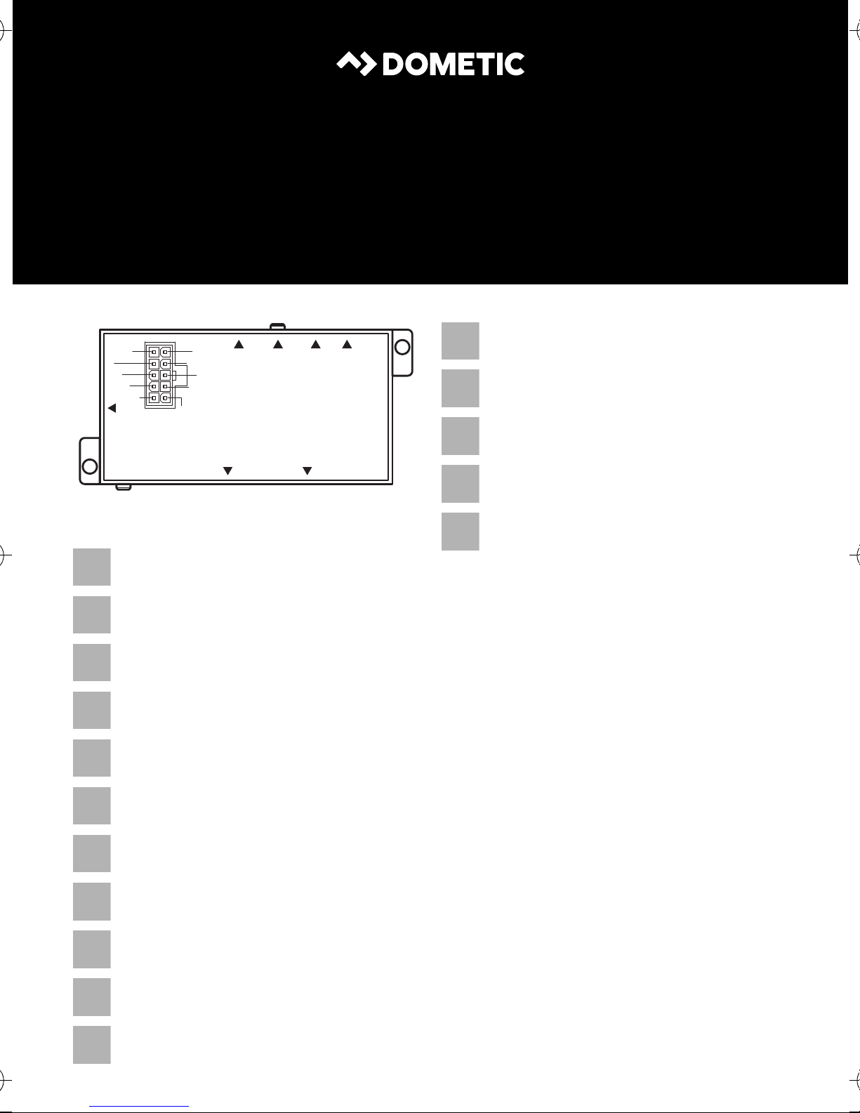
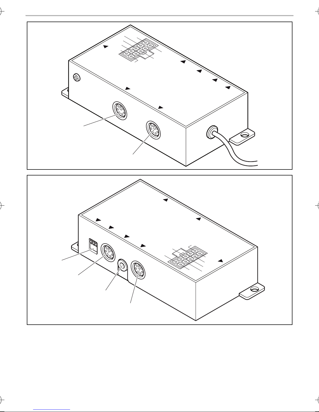
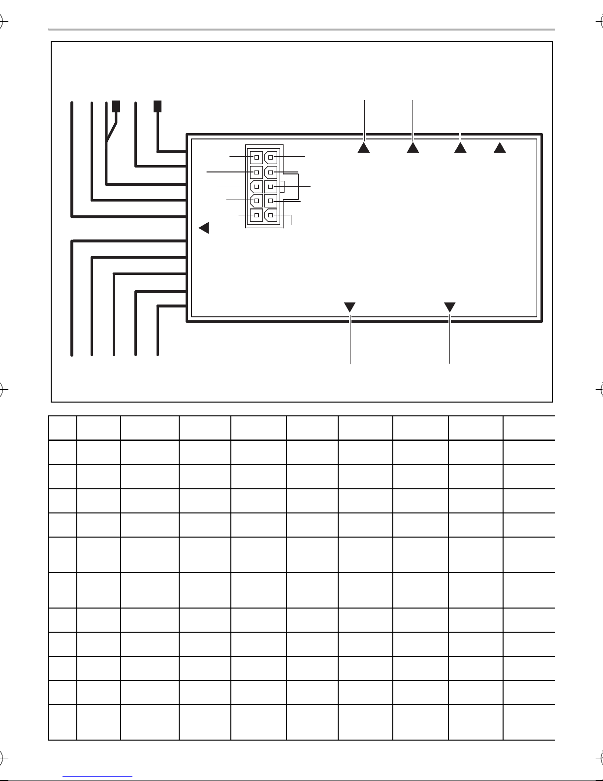
Connections and controls
No. in
fig. 4, page 4
1 Left (CA2) 6-pin mini DIN socket
2 Back (CA1) 6-pin mini DIN socket
No. in
fig. 5, page 4
3 R L B (Mirror S/W) DIP switch
4 DIN (Monitor) Monitor output
5 RCA (Monitor) Monitor output
Description Description
Connection for the left camera
Connection for the reversing camera
Description Description
Select mirror function
Connection for a monitor
Connection for a monitor with an A/V input
6 Right (CA3) 6-pin mini DIN socket
Connection for the right camera
4Proper usage
SWITCH300 is a control box that matches components from different reversing video systems to
each other. Up to three cameras can be connected to a monitor via SWITCH300.
5 Technical description
The control box SWITCH300 is used for the expansion of existing reversing video systems.
It possesses three separate controllable camera inputs, enabling e. g. operation with a reversing
and two side cameras or with three separate contollable cameras (for articulated buses, machine
monitoring etc.). In addition, for example, cameras that require different voltage can be
connected to each other.
Only one camera input is required on the monitor. The monitor can be automatically activated via
the corresponding control output.
All cameras can be activated manually. In addition, with corresponding cameras a mirror function
can be switched on so that the monitor picture corresponds to a view in the rear mirror.
The control box can be used with almost all cameras and monitors via various adapters
(accessories).
The control box can be connected to 12-V to 32-V DC voltage.
10

SWITCH300 Connecting the control box
EN
6 Connecting the control box
6.1 Tools required
To make and test the electrical connection, the following tools are required:
• insulating tape
• heat shrinking sleeve
• diode test lamp (fig. 1 1, page 2) or voltmeter (fig. 1 2, page 2)
• crimping tool (fig. 1 4, page 2)
• soldering iron (optional) (fig. 1 5, page 2)
• solder (optional) (fig. 1 6, page 2)
• cable bushing sleeves (optional)
6.2 Testing the control box and components
Before you install and connect the desired components, you should test the system. In this way you
can determine whether the components work together in the way you want. You thus avoid having
to dismantle the components later.
To test the system, proceed as follows:
➤ Lay out the individual devices.
➤ Connect the devices as described in the following chapter, but without securing the cables.
➤ If necessary, connect the control cables.
➤ Switch the system on.
➤ Check to see whether the components are working together as desired.
✓ If the system is working to your satisfaction, you can secure the devices and cables.
6.3 Connecting the control box
NOTICE!
A
• Ensure that all lines are connected correctly. The control line may never be
connected to earth; doing so can damage the device. Make especially sure to
insulate the bare end of the control line when it is not in use and thus not connected.
• If you possess a monitor that may only be used for 12 V and 24-V electrics is being
used, a voltage converter must be installed.
11

Connecting the control box SWITCH300
EN
The circuit diagram for the control box can be found in fig. 6, page 5:
Pos. Connection name
rt/sw Red/black cable: connection to the two-pin switch
sw Black cable: Connection to earth (terminal 31)
ws White cable:
• Connection to the control cable of the three-pin switch for the right-hand
camera (connection to R switch-plug)
• Connection to the two-pin switch
gr Grey cable: Connection to the control line of the three-pin switch for the reverse
camera (connection to switch plug L)
rt Red cable: Connection to +12 V to +24 V (e. g. switched positive, terminal 15)
bl Blue cable: Connection to the monitor control line (standby/monitor on)
gn Green cable: Connection to the right indicator
br Brown cable: Connection to the left indicator light
ge Yellow cable: Connection to the control wire of the three-pin switch for the left
or Orange cable: Connection to the reversing light
1 Camera connection 1
2 Camera connection 2
3 Camera connection 3
4a Output for reversing monitor (RCA)
4b Output for reversing monitor (DIN)
I
camera (connection to switch plug B)
NOTE
SWITCH300 matches different reversing video components to each other, but no
video standards. For this reason camera and monitor must match (PAL with PAL and
NTSC with NTSC). Most LCD monitors support both standards.
12

SWITCH300 Using the control box
EN
7 Using the control box
7.1 Manual operation
You can operate the control box manually. To do this, fit the two-stage switch (fig. 3 4, page 3)
supplied to a suitable place on the dashboard and connect it to the black/red and white cable.
With manual operation, you activate a particular camera by hand via the three-stage switch
(fig. 3 3, page 3) supplied.
In manual operation, a switch signal is sent via the blue cable which can activate the monitor.
➤ Place the two-stage switch in the required position to switch on the corresponding camera:
– I: manual operation is switched on
– 0: manual operation is switched off (the three-stage switch does not have a function)
➤ Connect the cables of the three-stage switch (fig. 3 3, page 3) according to the assignment
on page 12.
➤ Place the three-stage switch in the required position to switch on the corresponding camera:
– B: reversing camera (CA1) (fig. 6 1, page 5)
– L: left camera (CA2) (fig. 6 2, page 5)
– R right camera (CA3) (fig. 6 3, page 5)
NOTE
I
There is no signal on the control cable of the monitor during manual operation when
the switch is connected.
7.2 Automatic operation
You can operate the control box in automatic mode. In the automatic mode the cameras switch on
or off automatically according to the control signal present. The monitor is activated automatically
via the control box.
NOTE
I
➤ Connect the green line of the vehicle electrics connection cable to the right indicator light.
➤ Connect the brown line of the vehicle electrics connection cable to the left indicator light.
During automatic operation a signal of +12 V is present on the control cable of the
monitor when one of the indicators or the reverse gear is activated.
The camera whose control cable is active is always activated in automatic mode
(priority to reverse gear). If the situation arises, a switch position deviating from this is
ignored.
➤ Connect the orange line of the vehicle electrics connection cable to the reversing light.
13

Guarantee SWITCH300
EN
E4
10R-03 1855
8Guarantee
The statutory warranty period applies. If the product is defective, please contact the
manufacturer's branch in your country (see the back of the instruction manual for the addresses) or
your retailer.
For repair and guarantee processing, please include the following documents when you send in
the device:
• A copy of the receipt with purchasing date
• A reason for the claim or description of the fault
9Disposal
➤ Place the packaging material in the appropriate recycling waste bins wherever possible.
If you wish to finally dispose of the product, ask your local recycling centre or specialist
dealer for details about how to do this in accordance with the applicable disposal
M
regulations.
10 Technical data
SWITCH300
Ref. no.: 9600000067
Size (W x H x D): 130 x 30 x 57 mm
Operating voltage: 12 V – 32 Vg
Power consumption: max. 0.84 W (without camera)
Control inputs: positive 12 V – 24 V power signals
14

SWITCH300 Hinweise zur Benutzung der Anleitung
DE
Bitte lesen Sie diese Anleitung vor der Inbetriebnahme sorgfältig durch und bewahren
Sie sie auf. Geben Sie sie im Falle einer Weitergabe des Produktes an den Nutzer weiter.
Inhaltsverzeichnis
1 Hinweise zur Benutzung der Anleitung . . . . . . . . . . . . . . . . . . . . . . . . . . . . . . . . . . . . . . . . . 15
2 Sicherheits- und Einbauhinweise. . . . . . . . . . . . . . . . . . . . . . . . . . . . . . . . . . . . . . . . . . . . . . 16
3 Lieferumfang . . . . . . . . . . . . . . . . . . . . . . . . . . . . . . . . . . . . . . . . . . . . . . . . . . . . . . . . . . . . . . 17
4 Bestimmungsgemäßer Gebrauch . . . . . . . . . . . . . . . . . . . . . . . . . . . . . . . . . . . . . . . . . . . . . 18
5 Technische Beschreibung . . . . . . . . . . . . . . . . . . . . . . . . . . . . . . . . . . . . . . . . . . . . . . . . . . . 18
6 Schaltbox anschließen . . . . . . . . . . . . . . . . . . . . . . . . . . . . . . . . . . . . . . . . . . . . . . . . . . . . . . 19
7 Schaltbox benutzen . . . . . . . . . . . . . . . . . . . . . . . . . . . . . . . . . . . . . . . . . . . . . . . . . . . . . . . . 21
8 Gewährleistung . . . . . . . . . . . . . . . . . . . . . . . . . . . . . . . . . . . . . . . . . . . . . . . . . . . . . . . . . . .22
9 Entsorgung . . . . . . . . . . . . . . . . . . . . . . . . . . . . . . . . . . . . . . . . . . . . . . . . . . . . . . . . . . . . . . .22
10 Technische Daten . . . . . . . . . . . . . . . . . . . . . . . . . . . . . . . . . . . . . . . . . . . . . . . . . . . . . . . . . .22
1 Hinweise zur Benutzung der Anleitung
ACHTUNG!
A
I
Nichtbeachtung kann zu Materialschäden führen und die Funktion des Produktes
beeinträchtigen.
HINWEIS
Ergänzende Informationen zur Bedienung des Produktes.
15

Sicherheits- und Einbauhinweise SWITCH300
DE
2 Sicherheits- und Einbauhinweise
Der Hersteller übernimmt in folgenden Fällen keine Haftung für Schäden:
• Beschädigungen am Produkt durch mechanische Einflüsse und Überspannungen
• Veränderungen am Produkt ohne ausdrückliche Genehmigung vom Hersteller
• Verwendung für andere als die in der Anleitung beschriebenen Zwecke
ACHTUNG!
A
A
Klemmen Sie wegen der Kurzschlussgefahr vor Arbeiten an der Fahrzeugelektrik
immer den Minuspol ab.
Bei Fahrzeugen mit Zusatzbatterie müssen Sie an dieser ebenfalls den Minuspol
abklemmen.
ACHTUNG!
Unzureichende Leitungsverbindungen können zur Folge haben, dass durch
Kurzschluss
• Kabelbrände entstehen,
• der Airbag ausgelöst wird,
• elektronische Steuerungseinrichtungen beschädigt werden,
• elektrische Funktionen ausfallen (Blinker, Bremslicht, Hupe, Zündung, Licht).
ACHTUNG!
A
Beachten Sie deshalb folgende Hinweise:
• Verwenden Sie bei Arbeiten an den folgenden Leitungen nur isolierte Kabelschuhe, Stecker
und Flachsteckhülsen.
– 30 (Eingang von Batterie Plus direkt),
– 15 (Geschaltetes Plus, hinter Batterie),
– 31 (Rückleitung ab Batterie, Masse),
– 58 (Rückfahrscheinwerfer).
Verwenden Sie keine Lüsterklemmen.
• Verwenden Sie eine Krimpzange zum Verbinden der Kabel.
Für Verbindungen, die nicht wieder gelöst werden sollen, können Sie die Kabelenden
miteinander verlöten und anschließend isolieren.
Achten Sie auf einen korrekten Anschluss aller Leitungen. Es darf nie zu einer Verbindung der Steuerleitung mit Masse kommen, da sonst ein Geräteschaden eintreten
kann. Isolieren Sie insbesondere das blanke Ende der Steuerleitung, wenn sie nicht
gebraucht und daher nicht angeschlossen wird!
• Schrauben Sie das Kabel bei Anschlüssen an Leitung 31 (Masse)
– mit Kabelschuh und Zahnscheibe an eine fahrzeugeigene Masseschraube oder
– mit Kabelschuh und Blechschraube an das Karosserieblech.
Achten Sie auf eine gute Masseübertragung!
16

SWITCH300 Lieferumfang
DE
Beim Abklemmen des Minuspols der Batterie verlieren alle flüchtigen Speicher der Komfortelektronik ihre gespeicherten Daten.
• Folgende Daten müssen Sie je nach Fahrzeugausstattung neu einstellen:
–Radiocode
–Fahrzeuguhr
– Zeitschaltuhr
– Bordcomputer
– Sitzposition
Hinweise zur Einstellung finden Sie in der jeweiligen Bedienungsanleitung.
Beachten Sie folgende Hinweise bei der Arbeit an elektrischen Teilen:
• Benutzen Sie zum Prüfen der Spannung in elektrischen Leitungen nur eine Diodenprüflampe
(Abb. 1 1, Seite 2) oder ein Voltmeter (Abb. 1 2, Seite 2).
Prüflampen mit einem Leuchtkörper (Abb. 1 3, Seite 2) nehmen zu hohe Ströme auf,
wodurch die Fahrzeugelektronik beschädigt werden kann.
• Beachten Sie beim Verlegen der elektrischen Anschlüsse, dass diese
– nicht geknickt oder verdreht werden,
–nicht an Kanten scheuern,
– nicht ohne Schutz durch scharfkantige Durchführungen verlegt werden (Abb. 2, Seite 2).
• Isolieren Sie alle Verbindungen und Anschlüsse.
• Sichern Sie die Kabel gegen mechanische Beanspruchung durch Kabelbinder oder
Isolierband, z. B. an vorhandenen Leitungen.
3Lieferumfang
Nr. in Abb. 3,
Seite 3
1 1 Schaltbox 9600000067
21Anschlusskabel Bordnetz
3 1 Dreistufiger Schalter zur manuellen
4 1 Zweistufiger Schalter zur Aktivierung
5 1 Verbindungskabel Schaltbox – Monitor RV-502-M/M
Menge Bezeichnung Artikel-Nr.
Aktivierung der Kameras
der manuellen Bedienung
– 1 Montagematerial
17

Bestimmungsgemäßer Gebrauch SWITCH300
DE
Anschlüsse und Bedienelemente
Nr. in Abb. 4,
Seite 4
1 Left (CA2) 6-polige Mini-DIN-Buchse
2 Back (CA1) 6-polige Mini-DIN-Buchse
Nr. in Abb. 5,
Seite 4
3 R L B (Mirror S/W) DIP-Schalter
4 DIN (Monitor) Monitor-Ausgang
5 RCA (Monitor) Monitor-Ausgang
Bezeichnung Bezeichnung
Anschluss der linken Kamera
Anschluss der Rückfahrkamera
Bezeichnung Bezeichnung
Auswahl der Spiegelfunktion
Anschluss eines Monitors
Anschluss eines Monitor mit A/V-Eingang
6 Right (CA3) 6-polige Mini-DIN-Buchse
Anschluss der rechten Kamera
4 Bestimmungsgemäßer Gebrauch
SWITCH300 ist eine Schaltbox, die Komponenten aus verschiedenen Rückfahrvideosystemen
aneinander anpasst. Über den SWITCH300 können bis zu drei Kameras an einen Monitor angeschlossen werden.
5 Technische Beschreibung
Die Schaltbox SWITCH300 dient zur Erweiterung von vorhandenen Rückfahrvideosystemen. Sie
besitzt drei getrennt voneinander steuerbare Kamera-Eingänge, so dass z. B. ein Betrieb mit einer
Rückfahr- und zwei Seitenkameras oder mit drei getrennt steuerbaren Kameras (für Gelenkbusse,
Maschinenüberwachung usw.) möglich ist. Außerdem können z. B. Kameras, die unterschiedliche
Spannungen benötigen, miteinander verschaltet werden.
Am Monitor ist nur ein Kameraeingang notwendig. Der Monitor kann über den entsprechenden
Steuerausgang automatisch aktiviert werden.
Alle Kameras sind manuell aktivierbar. Außerdem kann mit entsprechenden Kameras eine Spiegelfunktion geschaltet werden, so dass das Monitorbild einem Blick in den Rückspiegel entspricht.
Über verschiedene Adapter (Zubehör) ist die Schaltbox mit fast allen Kameras und Monitoren des
Herstellers einsetzbar.
Die Schaltbox kann an 12 V bis 32 V Gleichspannung angeschlossen werden.
18

SWITCH300 Schaltbox anschließen
DE
6 Schaltbox anschließen
6.1 Benötigtes Werkzeug
Für den elektrischen Anschluss und seine Überprüfung benötigen Sie folgende Hilfsmittel:
• Isolierband
• Wärmeschrumpfschlauch
• Diodenprüflampe (Abb. 1 1, Seite 2) oder Voltmeter (Abb. 1 2, Seite 2)
• Krimpzange (Abb. 1 4, Seite 2)
• Ggf. Lötkolben (Abb. 1 5, Seite 2)
• Ggf. Lötzinn (Abb. 1 6, Seite 2)
• Ggf. Kabeldurchführungstüllen
6.2 Schaltbox und Komponenten testen
Bevor Sie die Schaltbox und die gewünschten Komponenten fest montieren und verdrahten,
sollten Sie das System testen. Dadurch können Sie feststellen, ob die Komponenten zusammen
so arbeiten, wie Sie es wünschen. Dadurch vermeiden Sie, Komponenten wieder ausbauen zu
müssen.
Gehen Sie zum Testen wie folgt vor:
➤ Legen Sie die einzelnen Geräte aus.
➤ Schließen Sie die Geräte an wie im folgenden Kapitel beschrieben, aber ohne die Leitungen
fest zu verlegen.
➤ Schließen Sie ggf. die Steuerleitungen an.
➤ Schalten Sie das System ein.
➤ Testen Sie, ob die Komponenten wie zusammen gewünscht arbeiten.
✓ Wenn das System zu Ihrer Zufriedenheit arbeitet, können Sie die Geräte und Leitungen fest
verlegen.
6.3 Schaltbox anschließen
ACHTUNG!
A
• Achten Sie auf einen korrekten Anschluss aller Leitungen. Es darf nie zu einer Ver-
bindung der Steuerleitung mit Masse kommen, da sonst ein Geräteschaden eintreten kann. Isolieren Sie insbesondere das blanke Ende der Steuerleitung, wenn
sie nicht gebraucht und daher nicht angeschlossen wird!
• Wenn Sie einen Monitor besitzen, der nur für 12 V zugelassen ist, und ein
24-V-Bordnetz vorhanden ist, müssen Sie einen Spannungswandler installieren.
19
Schaltbox anschließen SWITCH300
DE
Den Schaltplan für die Schaltbox finden Sie in Abb. 6, Seite 5:
Pos. Bezeichnung des Anschlusses
rt/sw Rot/Schwarzes Kabel: Anschluss an den zweipoligen Schalter
sw Schwarzes Kabel: Anschluss an Masse (Klemme 31)
ws Weißes Kabel:
• Anschluss an die Steuerleitung des dreipoligen Schalters für die rechte
Kamera (Anschluss an Schalter-Stecker R)
• Anschluss an den zweipoligen Schalter
gr Graues Kabel: Anschluss an die Steuerleitung des dreipoligen Schalters für die
Rückfahrkamera (Anschluss an Schalter-Stecker L)
rt Rotes Kabel: Anschluss an +12 V bis +24 V (z. B. geschaltetes Plus, Klemme 15)
bl Blaues Kabel: Anschluss an die Steuerleitung des Monitors
(Standby/Monitor an)
gn Grünes Kabel: Anschluss an den rechten Blinker
br Braunes Kabel: Anschluss an den linken Blinker
ge Gelbes Kabel: Anschluss an die Steuerleitung des dreipoligen Schalters für die
or Orangefarbenes Kabel: Anschluss an die Rückfahrleuchte
1 Kamera-Anschluss 1
2 Kamera-Anschluss 2
3 Kamera-Anschluss 3
4a Ausgang für Rückfahrmonitor (Cinch)
4b Ausgang für Rückfahrmonitor (DIN)
I
linke Kamera (Anschluss an Schalter-Stecker B)
HINWEIS
Der SWITCH300 passt verschiedene Rückfahrvideo-Komponenten aneinander an,
aber keine Videostandards. Daher müssen Kamera und Monitor zueinander passen
(PAL mit PAL und NTSC mit NTSC). Die meisten LCD-Monitore unterstützen beide
Standards.
20

SWITCH300 Schaltbox benutzen
DE
7 Schaltbox benutzen
7.1 Manuell betreiben
Sie können die Schaltbox manuell betreiben. Dazu montieren Sie den mitgelieferten zweistufigen
Schalter (Abb. 3 4, Seite 3) an geeigneter Stelle auf dem Armaturenbrett und schließen ihn an
der schwarz/roten und weißen Leitung an. Im manuellen Betrieb aktivieren Sie eine bestimmte
Kamera über den mitgelieferten dreistufigen Schalter (Abb. 3 3, Seite 3) von Hand.
Im manuellen Betrieb wird über die blaue Leitung ein Schaltsignal geliefert, mit dem der Monitor
aktiviert werden kann.
➤ Stellen Sie den zweistufigen Schalter in die gewünschte Stellung, um die zugehörige Kamera
einzuschalten:
– I: manuelle Bedienung eingeschaltet
– 0: manuelle Bedienung ausgeschaltet (der dreistufige Schalter ist ohne Funktion)
➤ Schließen Sie die Leitungen des dreistufigen Schalters (Abb. 3 3, Seite 3) gemäß der
Zuordnung auf Seite 20 an.
➤ Stellen Sie den dreistufigen Schalter in die gewünschte Stellung, um die zugehörige Kamera
einzuschalten:
– B: Rückfahrkamera (CA1) (Abb. 6 1, Seite 5)
– L: linke Kamera (CA2) (Abb. 6 2, Seite 5)
– R: rechte Kamera (CA3) (Abb. 6 3, Seite 5)
HINWEIS
I
Wenn der Schalter angeschlossen ist, liegt an der Steuerleitung des Monitor im
manuellen Betrieb kein Signal an.
7.2 Automatisch betreiben
Sie können die Schaltbox im Automatikbetrieb betreiben. Im Automatikbetrieb schalten sich die
Kameras entsprechend der anliegenden Steuersignale automatisch ein oder aus. Der Monitor
wird durch die Schaltbox automatisch aktiviert.
HINWEIS
I
➤ Schließen Sie die grüne Leitung des Bordnetz-Anschlusskabels an die rechte Blinkerlampe an.
➤ Schließen Sie die braune Leitung des Bordnetz-Anschlusskabels an die linke Blinkerlampe an.
Im automatischen Betrieb liegt an der Steuerleitung des Monitor ein Signal von +12 V
an, wenn einer der Blinker oder der Rückwärtsgang betätigt wird.
Im automatischen Betrieb wird in jedem Fall die Kamera (Priorität auf Rückwärtsgang)
aktiviert, deren Steuerleitung aktiv ist. Eine ggf. davon abweichende Schalterstellung
wird ignoriert.
➤ Schließen Sie die orangefarbene Leitung des Bordnetz-Anschlusskabels an den Rückfahr-
scheinwerfer an.
21

Gewährleistung SWITCH300
DE
E4
10R-03 1855
8Gewährleistung
Es gilt die gesetzliche Gewährleistungsfrist. Sollte das Produkt defekt sein, wenden Sie sich bitte
an die Niederlassung des Herstellers in Ihrem Land (Adressen siehe Rückseite der Anleitung) oder
an Ihren Fachhändler.
Zur Reparatur- bzw. Gewährleistungsbearbeitung müssen Sie folgende Unterlagen mitschicken:
• eine Kopie der Rechnung mit Kaufdatum,
• einen Reklamationsgrund oder eine Fehlerbeschreibung.
9Entsorgung
➤ Geben Sie das Verpackungsmaterial möglichst in den entsprechenden Recycling-Müll.
Wenn Sie das Produkt endgültig außer Betrieb nehmen, informieren Sie sich bitte beim
nächsten Recyclingcenter oder bei Ihrem Fachhändler über die zutreffenden
M
Entsorgungsvorschriften.
10 Technische Daten
SWITCH300
Artikel-Nr.: 9600000067
Maße (BxHxT): 130x30x57mm
Betriebsspannung: 12V–32Vg
Leistungsaufnahme: max. 0,84 W (ohne Kameras)
Steuereingänge: positive Spannungssignale 12 V – 24 V
22

SWITCH300 Remarques concernant l’utilisation de cette notice
FR
Veuillez lire ce manuel attentivement avant de mettre l'appareil en service et conservez-le. En cas de passer le produit, veuillez le transmettre au nouvel acquéreur.
Table des matières
1 Remarques concernant l’utilisation de cette notice . . . . . . . . . . . . . . . . . . . . . . . . . . . . . . .23
2 Consignes de sécurité et instructions de montage. . . . . . . . . . . . . . . . . . . . . . . . . . . . . . . .24
3 Contenu de la livraison . . . . . . . . . . . . . . . . . . . . . . . . . . . . . . . . . . . . . . . . . . . . . . . . . . . . . .26
4 Usage conforme . . . . . . . . . . . . . . . . . . . . . . . . . . . . . . . . . . . . . . . . . . . . . . . . . . . . . . . . . . .27
5 Description technique . . . . . . . . . . . . . . . . . . . . . . . . . . . . . . . . . . . . . . . . . . . . . . . . . . . . . .27
6 Raccordement de la boîte de commande. . . . . . . . . . . . . . . . . . . . . . . . . . . . . . . . . . . . . . .27
7 Utilisation de la boîte de commande. . . . . . . . . . . . . . . . . . . . . . . . . . . . . . . . . . . . . . . . . . .30
8 Garantie. . . . . . . . . . . . . . . . . . . . . . . . . . . . . . . . . . . . . . . . . . . . . . . . . . . . . . . . . . . . . . . . . . 31
9 Retraitement . . . . . . . . . . . . . . . . . . . . . . . . . . . . . . . . . . . . . . . . . . . . . . . . . . . . . . . . . . . . . . 31
10 Caractéristiques techniques. . . . . . . . . . . . . . . . . . . . . . . . . . . . . . . . . . . . . . . . . . . . . . . . . . 31
1 Remarques concernant l’utilisation de cette notice
AVIS !
A
I
Le non-respect de ces consignes peut entraîner des dommages matériels et des dysfonctionnements du produit.
REMARQUE
Informations complémentaires sur l'utilisation du produit.
23

Consignes de sécurité et instructions de montage SWITCH300
FR
2 Consignes de sécurité et instructions de montage
Le fabricant décline toute responsabilité pour des dommages dans les cas suivants :
• des influences mécaniques et des surtensions ayant endommagé le matériel
• des modifications apportées au produit sans autorisation explicite de la part du fabricant
• une utilisation différente de celle décrite dans la notice
AVIS !
A
A
Débranchez toujours le pôle négatif avant d'effectuer des travaux sur les éléments
électriques du véhicule, afin d’éviter tout risque de court-circuit.
Sur les véhicules équipés d'une batterie supplémentaire, vous devez également
débrancher le pôle négatif de cette dernière.
AVIS !
Tout branchement électrique inadéquat peut entraîner un court-circuit causant
• la combustion de câbles,
• le déclenchement de l'airbag,
• l’endommagement des dispositifs électroniques de commande,
• la défaillance des fonctions électriques (clignotants, stops, klaxon, allumage,
éclairage).
AVIS !
A
Veillez donc à respecter les consignes suivantes :
• Pour tous les travaux sur les lignes suivantes, n’utilisez que des cosses de câble, fiches et
alvéoles pour contacts plats isolés.
– 30 (entrée directe pôle positif de la batterie),
–15 (pôle positif connecté, derrière la batterie),
– 31 (circuit de retour à partir de la batterie, masse),
– 58 (feu de recul).
N’utilisez pas de dominos.
• Utilisez une pince de sertissage pour raccorder les câbles.
Pour les raccordements définitifs, vous pouvez assembler les extrémités des câbles par
soudure puis les isoler.
Veillez à ce que tous les raccordements soient correctement effectués. Tout
raccordement de la ligne de commande à la masse est interdit, sans quoi l'appareil
risquerait d'être endommagé. Veuillez isoler en particulier l'extrémité dénudée de la
ligne de commande lorsque celle-ci est inutilisée et donc débranchée !
• Pour les raccordements à la ligne électrique 31 (masse), vissez le câble
– à une vis de masse du véhicule, avec une cosse de câble et une rondelle crantée, ou bien
– à la carrosserie, avec une cosse de câble et une vis à tôle.
Assurez-vous que le transfert de masse se fait correctement !
24

SWITCH300 Consignes de sécurité et instructions de montage
FR
Lorsque vous débranchez le pôle négatif de la batterie, les mémoires volatiles de l’électronique de
confort perdent toutes les données enregistrées.
• Vous devez procéder à un nouveau réglage des données suivantes en fonction de l’équipement du véhicule :
–code radio
– horloge du véhicule
–minuterie
– ordinateur de bord
– position du siège
Les instructions de réglage sont énoncées dans les notices d’utilisation correspondantes.
Veillez à respecter les consignes suivantes lors de travaux sur des éléments électriques :
• Pour le contrôle de la tension des lignes électriques, n'utilisez qu'une lampe étalon à diodes
(fig. 1 1, page 2) ou un voltmètre (fig. 1 2, page 2).
Les lampes étalons avec corps lumineux (fig. 1 3, page 2) absorbent des courants trop élevés
qui pourraient endommager les systèmes électroniques du véhicule.
• Lors de l'installation des raccordements électriques, veillez à ce que ceux-ci
– ne soient ni pliés, ni tordus,
– ne frottent pas contre des arêtes,
– ne soient pas placés dans des passages à arêtes vives sans protection (fig. 2, page 2).
• Isolez toutes les connexions et tous les raccords.
• Protégez les câbles contre toute contrainte mécanique en les fixant par exemple aux lignes
existantes à l'aide de serre-câbles ou de ruban isolant.
25

Contenu de la livraison SWITCH300
FR
3 Contenu de la livraison
N° dans
fig. 3, page 3
1 1 Boîte de commande 9600000067
2 1 Câble de raccordement du réseau de
3 1 Commutateur à trois niveaux pour
4 1 Commutateur à deux niveaux pour
5 1 Câble de raccordement boîte de
–1Matériel de montage
Raccords et éléments de commande
N° sur la
fig. 4, page 4
Quan-
tité
Désignation Désignation
Désignation N° d'article
bord
activation manuelle des caméras
activation de la commande manuelle
commande –moniteur
RV-502-M/M
1 Left (CA2) Mini DIN femelle à 6 pôles
2 Back (CA1) Mini DIN femelle à 6 pôles
N° sur la
fig. 5, page 4
3 R L B (Mirror S/W) Commutateur DIP
4 DIN (Monitor) Sortie moniteur
5 RCA (Monitor) Sortie moniteur
6 Right (CA3) Mini DIN femelle à 6 pôles
Raccordement de la caméra gauche
Raccordement de la caméra de recul
Désignation Désignation
Sélection de la fonction miroir
Raccordement d'un moniteur
Raccordement d'un moniteur équipé d'une
entrée A/V
Raccordement de la caméra droite
26

SWITCH300 Usage conforme
FR
4Usage conforme
La SWITCH300 est une boîte de commande qui adapte entre eux les composants de différents
systèmes vidéo de recul. Il est possible, au moyen de la SWITCH300, de raccorder jusqu'à trois
caméras à un moniteur.
5 Description technique
La boîte de commande SWITCH300 sert d'extension aux systèmes vidéo de recul déjà présents.
Elle possède trois entrées caméra pouvant être commandées individuellement de façon à permettre p. ex. un fonctionnement avec une caméra de recul et deux latérales ou avec trois caméras
commandées individuellemnt (pour bus articulés, surveillance de machines etc.). De plus, il est
possible, p. ex., de raccorder ensemble des caméras nécessitant des tensions différentes.
Une seule entrée caméra est nécessaire au niveau du moniteur. Le moniteur peut être activé
automatiquement via la sortie de commande correspondante.
Toutes les caméras peuvent être activées manuellement. Une fonction miroir peut être activée, de
plus, avec les caméras correspondantes de façon à ce que l'image du moniteur corresponde à
l'image dans le rétroviseur.
Différents adaptateurs (accessoires) permettent d'utiliser la boîte de commande avec presque
toutes les caméras et tous les moniteurs.
La boîte de commande peut être branchée sur une tension continue de 12 V à 32 V.
6 Raccordement de la boîte de commande
6.1 Outils nécessaires
Pour le raccordement électrique et le contrôle de celui-ci, vous devez disposer du matériel
suivant :
• Ruban vinyl
• Gaine thermorétractable
• Lampe étalon à diode (fig. 1 1, page 2) ou voltmètre (fig. 1 2, page 2)
• Pince à sertir (fig. 1 4, page 2)
• Si nécessaire : fer à souder (fig. 1 5, page 2)
• Si nécessaire : étain à souder (fig. 1 6, page 2)
• Si nécessaire : passe-câbles
27

Raccordement de la boîte de commande SWITCH300
FR
6.2 Test de la boîte de commande et des composants
Vous devriez tester le système avant de fixer définitivement et de câbler la boîte de commande et
les composants désirés. Vous pouvez ainsi vérifier que les composants fonctionnent comme vous
le souhaitez. Cela vous évite de devoir redémonter les composants.
Pour procéder au test, procédez comme suit :
➤ Mettez en place les différents appareils.
➤ Raccordez les appareils comme cela est décrit dans le chapitre suivant sans toutefois poser
définitivement les lignes.
➤ Raccordez les lignes de commande si besoin.
➤ Allumez le système.
➤ Testez si les composants fonctionnent correctement ensemble.
✓ Si le fonctionnement du système vous satisfait, posez alors définitivement les appareils et les
lignes.
6.3 Raccordement de la boîte de commande
A
AVIS !
• Veillez à ce que tous les raccordements soient correctement effectués.
Tout raccordement de la ligne de commande à la masse est interdit, sans quoi
l'appareil risquerait d'être endommagé . Veuillez isoler en particulier l'extrémité
dénudée de la ligne de commande lorsque celle-ci est inutilisée et donc
débranchée !
• Si vous possédez un moniteur qui n'est autorisé que pour 12 V et que le réseau de
bord est de 24 V, il vous faut alors installer un transformateur de tension.
28
SWITCH300 Raccordement de la boîte de commande
FR
Le schéma électrique de la boîte de commande se trouve dans la fig. 6, page 5.
Pos. Désignation du raccordement
rt/sw Câble rouge/noir : raccordement au commutateur à deux pôles
sw Câble noir : raccordement à la masse (borne 31)
ws Câble blanc :
• Raccordement à la ligne de commande du commutateur à trois niveaux pour
la caméra de droite (raccordement au connecteur R du commutateur)
• raccordement au commutateur à deux pôles
gr Câble gris : raccordement à la ligne de commande du commutateur à trois
niveaux pour la caméra vidéo de recul (raccordement au connecteur L du
commutateur)
rt Câble rouge : raccordement sur +12 V à +24 V (p. ex. : plus connecté,
borne 15)
bl Câble bleu : raccordement à la ligne de commande du moniteur
(mode veille/moniteur allumé)
gn Câble vert : raccordement au clignotant droit
br Câble marron : raccordement au clignotant gauche
ge Câble jaune : raccordement à la ligne de commande du commutateur à trois
or Câble orange : raccordement au feu de recul
1 Raccordement de la caméra 1
2 Raccordement de la caméra 2
3 Raccordement de la caméra 3
4a Sortie pour le moniteur de recul (Cinch)
4b Sortie pour le moniteur de recul (DIN)
I
niveaux pour la caméra de gauche (raccordement au connecteur B du commutateur)
REMARQUE
La SWITCH300 adapte entre eux différents composants vidéo de recul mais pas
différentes normes vidéo. Il est donc impératif que caméra et moniteur aillent
ensemble (PAL avec PAL et NTSC avec NTSC). La plupart des moniteurs à cristaux
liquides supportent les deux normes.
29

Utilisation de la boîte de commande SWITCH300
FR
7 Utilisation de la boîte de commande
7.1 Fonctionnement manuel
Vous pouvez faire fonctionner manuellement la boîte de commande. Pour ce faire, montez le
commutateur à deux niveaux (fig. 3 4, page 3) à l’endroit adapté sur le tableau de bord et
raccordez-le au câble noir/rouge et au câble blanc. En mode manuel, vous activez manuellement
une caméra donnée grâce au commutateur à trois niveaux (fig. 3 3, page 3) fourni.
En mode manuel, le câble bleu fournit un signal de commutation qui permet d’activer le moniteur.
➤ Mettez le commutateur à deux niveaux dans la position souhaitée pour allumer la caméra
correspondante :
– I : commande manuelle activée
– 0: commande manuelle désactivée (le commutateur à trois niveaux est sans fonction)
➤ Raccordez les câbles du commutateur à trois niveaux (fig. 3 3, page 3) conformément à la
liste des correspondances de la page 29.
➤ Mettez le commutateur à trois niveaux dans la position souhaitée pour allumer la caméra
correspondante :
– B : caméra de recul (CA1) (fig. 6 1, page 5)
– L : caméra gauche (CA2) (fig. 6 2, page 5)
– R : caméra droite (CA3) (fig. 6 3, page 5)
REMARQUE
I
Si le commutateur est raccordé, aucun signal n'est présent au niveau de la ligne de
commande du moniteur, en mode manuel.
7.2 Fonctionnement automatique
Vous pouvez faire fonctionner automatiquement la boîte de commande. En mode automatique,
les caméras s'allument et s'éteignent automatiquement en fonction des signaux de commande
arrivant. Le moniteur est activé automatiquement par la boîte de commande.
REMARQUE
I
➤ Raccordez la ligne verte du câble de raccordement du réseau de bord à l'ampoule du
clignotant droit.
En mode automatique, un signal de +12 V est présent au niveau de la ligne de
commande du moniteur si un des clignotants ou la marche arrière a été actionné(e).
En mode automatique, la caméra dont la ligne de commande est active est allumée
dans tous les cas (priorité à la marche arrière). Toute autre position du commutateur est
ignorée.
➤ Raccordez la ligne marron du câble de raccordement du réseau de bord à l'ampoule du
clignotant gauche.
➤ Raccordez la ligne orange du câble de raccordement du réseau de bord au feu de recul.
30
 Loading...