

Dometic PerfectView M71L Installation And Operating Manual
ENDEFRESPTITNLDASV
NOFIRUPLSKCSHU
DRIVING SUPPORT
PERFECTVIEW
M71L
LCD M onitor
Installation and Operating Manual . . . . . . 9
LCD- Mon itor
Montage- und Bedienungsanleitung . . . 20
Ecran LCD
Instructions de montage
et de service . . . . . . . . . . . . . . . . . . . . . . . 32
Pantalla LCD
Instrucciones de montaje y de uso . . . . . 44
Monitor LCD
Instruções de montagem e manual de
instruções . . . . . . . . . . . . . . . . . . . . . . . . . 56
Monitor LCD
Istruzioni di montaggio e d’uso . . . . . . . .68
LCD- mon itor
Montagehandleiding en
gebruiksaanwijzing. . . . . . . . . . . . . . . . . . 80
LCD- mon itor
Monterings- og betjeningsvejledning. . . 92
LCD- mon itor
Monterings- och bruksanvisning . . . . . . 103
LCD- mon itor
Monterings- og bruksanvisning . . . . . . . 114
LCD- mon itor i
Asennus- ja käyttöohje. . . . . . . . . . . . . . 125
ЖК-монитор
Инструкция по монтажу
и эксплуатации. . . . . . . . . . . . . . . . . . . . 136
Monitor LCD
Instrukcja montażu i obsługi . . . . . . . . . 148
LCD m onitor
Návod na montáž a uvedenie
do prevádzky . . . . . . . . . . . . . . . . . . . . . 160
Monitor LCD
Návod k montáži a obsluze . . . . . . . . . . .171
LCD- mon itor
Szerelési és használati útmutató . . . . . . 182

PerfectView M71L
1
4
8
12 13 14
911
56 7
23
10
1
3
PerfectView M71L
2
3
4
5
6
7
4
PerfectView M71L
8
1 2
9
5
1
2
3
6
5
4
8 7
0
PerfectView M71L
6
PerfectView M71L
a
A
B
b
1 2
c
7
PerfectView M71L
132
9
6
5
8
4
12
7
13
10
11
d
8

PerfectView M71L Description of symbols
EN
Please read this instruction manual carefully before installati on and first use, and store
it in a safe place. If you pass on the product to another person, hand over this instruction manual along with it.
Table of contents
1 Description of symbols . . . . . . . . . . . . . . . . . . . . . . . . . . . . . . . . . . . . . . . . . . . . . . . . . . . . . . . 9
2 Safety and installation instructions . . . . . . . . . . . . . . . . . . . . . . . . . . . . . . . . . . . . . . . . . . . . . 10
3 Scope of delivery . . . . . . . . . . . . . . . . . . . . . . . . . . . . . . . . . . . . . . . . . . . . . . . . . . . . . . . . . . 12
4 Intended use . . . . . . . . . . . . . . . . . . . . . . . . . . . . . . . . . . . . . . . . . . . . . . . . . . . . . . . . . . . . . . 12
4 Intended use . . . . . . . . . . . . . . . . . . . . . . . . . . . . . . . . . . . . . . . . . . . . . . . . . . . . . . . . . . . . . . 12
5 Technical description . . . . . . . . . . . . . . . . . . . . . . . . . . . . . . . . . . . . . . . . . . . . . . . . . . . . . . . 12
6 Installing the LCD monitor . . . . . . . . . . . . . . . . . . . . . . . . . . . . . . . . . . . . . . . . . . . . . . . . . . . 13
7 Using the LCD monitor . . . . . . . . . . . . . . . . . . . . . . . . . . . . . . . . . . . . . . . . . . . . . . . . . . . . . . 17
8 Cleaning and maintaining the LCD monitor . . . . . . . . . . . . . . . . . . . . . . . . . . . . . . . . . . . . . 18
9 Warranty . . . . . . . . . . . . . . . . . . . . . . . . . . . . . . . . . . . . . . . . . . . . . . . . . . . . . . . . . . . . . . . . . 18
10 Disposal. . . . . . . . . . . . . . . . . . . . . . . . . . . . . . . . . . . . . . . . . . . . . . . . . . . . . . . . . . . . . . . . . . 18
11 Technical data . . . . . . . . . . . . . . . . . . . . . . . . . . . . . . . . . . . . . . . . . . . . . . . . . . . . . . . . . . . . . 19
1 Description of symbols
CAUTION!
!
A
Safety instruction: Failure to observe this instruction can lead to injury.
NOTICE!
Failure to observe this instruction can cause material damage and impair the function
of the product.
I
NOTE
Supplementary information for operating the product.
9

Safety and installation instructions PerfectView M71 L
EN
2 Safety and installation instructions
Please observe the prescribed safety instructions and stipulations from the vehicle
manufacturer and service workshops.
The manufacturer accepts no liability for damage in the following cases:
•
Faulty assembly or conn ection
•
Damage to the product resulting from mechanical influences and incorrect connection voltage
•
Alterations to the product without express permission from the manufacturer
•
Use for purposes other than those described in the operating manual
NOTICE! Risk of damage!
•
A
Therefore, please observe the following instructions:
•
When working on the following cables, only use insulated cable lugs, plugs and tab sleeves:
•
Use a crimping tool (fig. 1 12, page 3) to connect the cables.
•
Screw the cable when connecting cable 31 (earth)
If you disconnect the negative terminal of the battery, all data stored in the comfort electronics volatile memory will be lost.
•
The following data must be reset, depending on the vehicle equipment options:
10
To prevent the danger of short circuiting, always disconnect the negative terminal
of the vehicle's electrical system before working on it.
If the vehicle has an additional battery, its negative terminal should also be disconnected.
•
Inadequate supply line connections could result in short circuits, causing:
–Cable fires
– The airbag being triggered
– Damage to electronic control devices
– Electrical malfunctions (indicators, brake light, horn, ignition, lights)
– 30 (direct input from positive battery terminal)
–15 (connected positive terminal, behind the battery)
– 31 (return cable from the battery, earth)
– 58 (reversing light)
Do not use porcelain wire connectors.
– Screw on the cable using a cable lug and gear disc to one of the vehicle's earth bolts or
– Screw the cable to the sheet metal body work using a cable lug and a self-tapping screw.
Make sure there is a good earth connection.
–Radio code
– Vehicle clock
–Timer
– On-board computer
– Seat position

PerfectView M71L Safety and installation instructions
EN
You can find instructions for making these settings in the operating manual.
Note the following instructions during installation:
CAUTION!
•
!
Observe the following instructions when working with electrical parts:
•
When testing the voltage in electrical cables, only use a diode test lamp (fig. 1 1, page 3) or a
voltmeter (fig. 1 2, page 3).
Test lamps with a bulb (fig. 1 3, page 3) consume voltages which are too high and can dam-
age the vehicle's electronic system.
•
When making electrical connections, ensure that:
•
Insulate all connections.
•
Secure the cables against mechanical stress with cable binders or insulating tape, for example,
to existing lines.
Observe the following instructions when handling the LCD monitor:
!
Secure the monitor in such a way that it cannot become loose under any circumstances (sudden braking, accidents) and cause injuries to the occupants of the
vehicle.
•
Do not attach the monitor in the air bag deployment path, as this could cause injury
if the airbags are triggered.
– They are not kinked or twisted
– They do not rub on edges
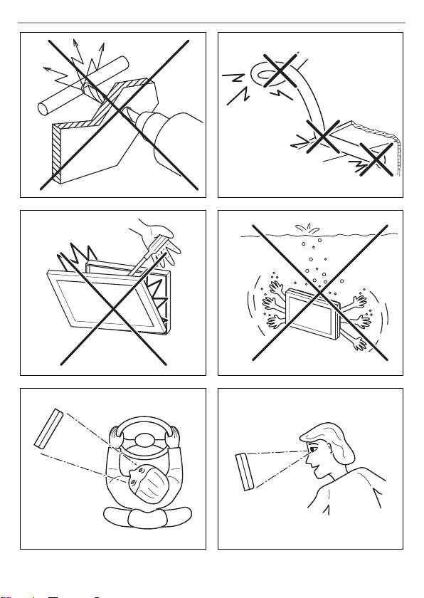
– They are not laid in sharp-edged through-holes without protection (fig. 3, page 4)
CAUTION!
•
People (including children) whose physical, sensory or mental capacities or whose
lack of experience or knowledge prevent them from using this product safely
should not use it without the supervision or instruction of a responsible person.
•
Do not open the monitor (fig. 4, page 4).
•
Do not immerse the monitor in water (fig. 5, page 4); the monitor is not waterproof.
•
The monitor must not impair your vision when driving (fig. 8, page 5).
•
Do not operate the monitor with wet hands.
•
Do not operate the monitor if the housing has been damaged.
11

Scope of delivery PerfectView M71L
EN
NOTICE!
•
A
Connect it to the correct voltage.
•
Do not use the monitor in areas which:
– Are subject to direct sunlight
– Are subject to strong temperature fluctuations
– Have high levels of humidity
– Are poorly ventilated
– Are dusty or oily
•
Do not press against the LCD display.
•
Do not drop the monitor.
•
If you use the monitor in vehicles, the vehicle sh ould be running during operation to
prevent the vehicle battery from discharging.
•
The picture quality can be impaired in the vicinity of electromagnetic fields.
For this reason do not mount the monitor near loudspeakers.
3Scope of delivery
No. in
fig. 9,
page 5
1 1 Monitor 9600011060
2 1 Monitor bracket 9102200193
31Monitor bracket cover –
– 1 Connection cable 9102200056
––Fastening material –
Quantity Description Ref. no.
4Intended use
The PerfectView M71L LCD monitor (ref no. 9600011060) is primarily intended for use in vehicles.
It can be used to connect cameras (e.g. a reversing video system) or other video sources.
The LCD monitor is designed for use in all vehicles.
The LCD monitor is suitable for commercial use.
5 Technical description
5.1 Function description
The LCD monitor can be connected to cameras (e.g. reversing video systems) or other video
sources (e.g. DVD players). It is possible to switch back and forth between video sources.
The monitor features control cables which allow the cameras to be a ctivated automatically.
12
PerfectView M71L Installing the LCD monitor
EN
It can operate up to four cameras, which can be activated via external control cables or manually.
This monitor also features a distance grid in the display which is activated automatically when the
reverse gear is engaged (AV1).
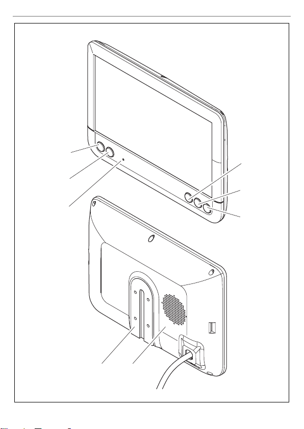
5.2 Control elements
The following control elements are located on the monitor:
No. in
fig. 0,
Description
page 6
1 Switches the monitor on and off.
2 Switches to setup mode.
3 The light sensor automatically adjusts the brightness of the display
to the ambient light.
4 – Reduces the audio volume or the selected parameter (brightness,
5 + Increases the audio volume or the selected parameter (brightness,
contrast, color).
contrast, color).
6 Selects the camera.
7Monitor bracket
8 Loudspeaker
6 Installing the LCD monitor
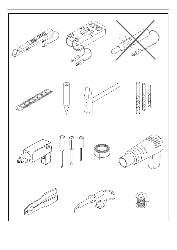
6.1 Tools required (fig. 1, page 3)
For installation and assembly you will need the following tools:
•
Measuring ruler (4)
•
Center punch (5)
•
Hammer (6)
•
Drill head set (7)
•
Drill (8)
•
Screwdriver (9)
To establish and test the electrical connection, the following tools are required:
•
Diode test lamp (1) or voltmeter (2)
•
Insulating tape (10)
13

Installing the LCD monitor PerfectView M71L
EN
•
Heat shrinking sleeve
•
Hot air blower (11)
•
Crimping tool (12)
•
Soldering iron (optional) (13)
•
Solder (optional) (14)
•
Cable bushing sleeves (optional)
To fasten the cables, you may require additional cable binders.
6.2 Installing the monitor
CAUTION! Beware of injury!
!
Note the following instructions during installation:
•
•
•
•
•
•
•
•
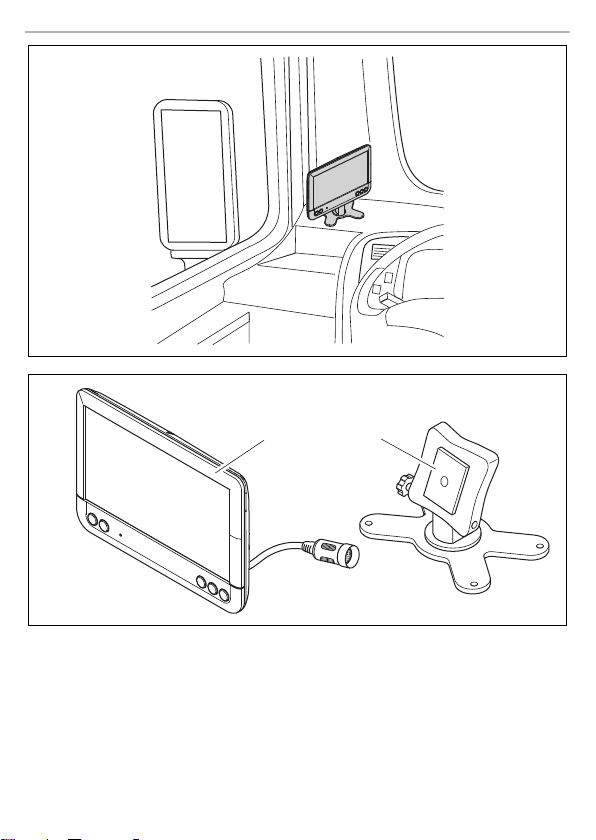
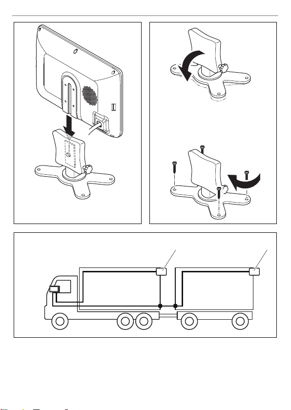
Choosing the installation location (fig. a, page 7)
➤ Place the monitor on the monitor bracket.
➤ Position the monitor and the attached monitor bracket provisionally.
➤ Mark the outlines of the corners of the support base on the dashboard.
➤ Take the monitor off the monitor bracket.
Screwing the monitor bracket onto the dashboard (fig. b, page 7)
➤ Hold the support base within the outlines marked beforehand.
➤ Fix the monitor bracket in place using suitable screws.
Select the location of the monitor so that it cannot injure the passengers in the vehicle
under any circumstances (e.g. sudden braking, road traffic accidents).
Select an installation location that provides an unobstructed view of the monitor (fig. 6 and
fig. 7, page 4).
Never install the monitor in areas where your head could hit it or in the airbag deployment path.
This could cause injury if the airbag opens.
The monitor must not impair your vision when driving (fig. 8, page 5).
The installation location should be flat.
Check that there is sufficient space underneath the installation location to attach the washers
and nuts.
Check beforehand that there is suffici ent space on the other side for the drill head to come out
(fig. 2, page 4).
Bear in mind the weight of the monitor. Provide reinforcement if necessary (larger washers or
plates).
Make sure you can lay the connection cable to the monitor.
14

PerfectView M71L Installing the LCD monitor
EN
Fastening the monitor
➤ Set the monitor on the monitor bracket and secure it with the knurled nut (fig. a, page 7).
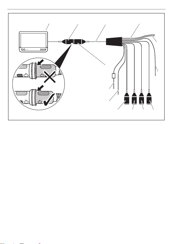
6.3 Connecting the monitor electrically
The circuit diagram for the LCD monitor can be found in fig. d, page 8.
No. Description
1Monitor
220-pin socket
3 Monitor line
4 20-pin plug
5 12 – 24 V positive cable (red): connected to the positive terminal of the
6 Earth cable (black): connected to the negative termina l of the voltage
7 Cable (green): control input for video input AV1,
8 Cable (white): control input for video input AV2,
9 6-pin AV1 socket (connection to video source 1)
10 6-pin AV2 socket (connection to video source 2)
11 6-pin AV3 socket (connection to video source 3)
12 6-pin AV4 socket (connection to video source 4,
13 Cable (blue): control input for video input AV3
ignition (connected positive, ter minal 15) or the positive terminal of the ba ttery (terminal 30)
source
such as for connecting the reversing light
such as for the side camera
with video signal detection)
NOTICE!
A
Observe the following instructions when laying the connection cables:
•
Cables and cable connections that are not properly installe d will cause malfunctions or
damage to components.
Correct installation of cables and cable connections ensures lasting and trouble-free
operation of the retrofitted components.
If possible, use existing through-holes for feeding through the connection cables, or other suitable options, such as ventilation grilles. If there are no existing through-holes, you must drill a
hole of ∅ 22 mm. Check beforehand that there is sufficient space on the other side for the drill
head to emerge (fig. 2, page 4).
15

Installing the LCD monitor PerfectView M71L
EN
•
Cover the holes with the feed through (fig. b 1, page 7) in the base of the monitor bracket.
•
To prevent damage to the cables, when laying them ensure that there is always a sufficient distance to vehicle components which can become hot (lights, heaters, ventilators etc.).
•
When laying the cables (fig. 3, page 4), make sure:
– They are not kinked or twisted
– They do not rub on edges
– They are not laid in sharp-edged through-holes without protection
Connecting the monitor as a reversing video system (fig. d, page 8)
➤ Lay the connection cable for the monitor bracket on the dashboard.
➤ Insert the plug of the monitor cable (2) into the socket (4) of the connection cable (3).
Wait until you hear the plug snap in.
NOTICE! Risk of damage!
A
➤ Connect the red and black cables of the connection cable to a suitable voltage supply:
➤ If the monitor is to be activated when reverse gear is selected, connect the green cable (7) to
I
➤ If the monitor is to be activated e.g. when the indicator is flashing, connect the following con-
I
Make sure the polarity is correct when connecting to a voltage source.
– Connect the red cable (5) to terminal 15 (ignition).
– Connect the black cable (6) to terminal 31 (earth).
the positive cable of the reversing light.
NOTE
If voltage is present at the green cable (7), the reversing camera is activated. The
reversing camera has priority.
trol cable to a positive cable of the indicator:
–white cable (8), blue cable (13)
NOTE
If voltage is present in this control cable, the video inputs AV2 and AV3 will be activated.
This control cable is used as a signal cable for the activation of a side camera when an indicator is
flashing, for example.
➤ If necessary, connect the AV1 socket (9) of the connection cable to the plug of video source 1
(e.g. reversing camera).
➤ If necessary, connect the AV2 socket (10) of the connection cable to the plug of the video
source 2 (e.g. side camera).
➤ If necessary, connect the AV3 socket (11) of the connection cable to the plug of video source 3
(e.g. camera).
16

PerfectView M71L Using the LCD monitor
EN
NOTE
I
Connecting an additional reversing camera (trailer operation)
➤ If necessary, connect socket AV4 (12) of the connection cable to the plug of the additional
Observe the power consumption of the video system. The cameras are equipped with
heaters. A maximum current of 1.5A can flow (three cameras in heating mode). Use a
disconnecter switch for direct connection to the battery. This allows you to disconnect
the video system from the battery easily if you are no longer using the vehicle.
reversing camera.
7 Using the LCD monitor
7.1 Switching on the monitor
➤ If the monitor is switched off, press the button (fig. 0 2, page 6) to switch the monitor on.
➤ The button lights up blue.
✓ The picture appears.
7.2 Switching off the monitor
➤ Press the button (fig. 0 2, page 6) to switch off the monitor.
➤ The button lights up red.
✓ The picture disappears.
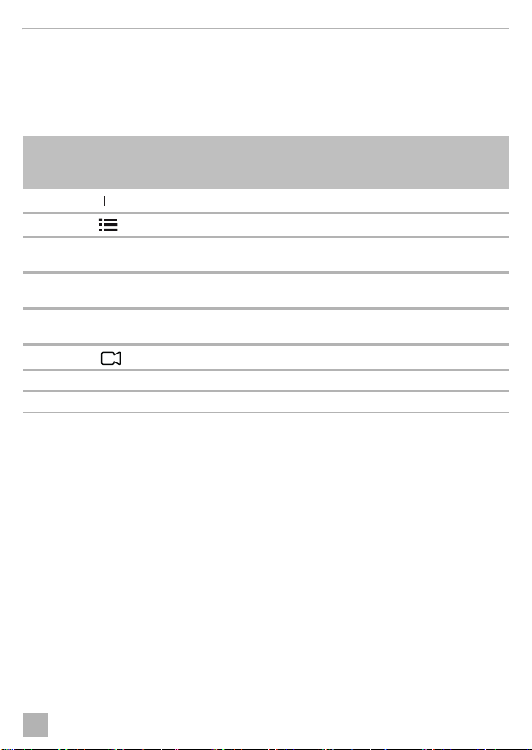
7.3 Setting the monitor
To set the monitor to suit your requirements, proceed as follows (fig. 0, page 6):
➤ Press the “ ” button (5) to call up the required parameter.
✓ The parameters to be set are displayed in the following sequence:
– Brightness: 0 – 100
–Contrast: 0 – 100
– Saturation: 0 – 100
–Volume: 0 – 100
– Language: English, French, German
– Mirror AV1/AV2/AV3/AV4: Yes or No
– Video AV1/AV2/AV3/AV4: Yes or No
– Distance grid: ON or OFF
– Trailer detection: ON or OFF
– Day/night mode: ON or OFF
– Default: Default setting for all parameters
➤ Press the “+” button (3) or the “–” button (4) to set the required parameter.
➤ Press the “+” button (3) to increase the value of the selected parameter.
➤ Press the “–” button (4) to reduce the value of the selected parameter.
17

Cleaning and maintaining the LCD monitor PerfectView M71 L
EN
7.4 Setting the video source
Proceed as follows to set the video source (fig. 0, page 6):
➤ If you would like to switch to a different video source, press the button (6).
✓ The monitor changes the camera in the order Camera 1 – Camera 2 – Camera 3 – Camera 4.
With the Video AV1/AV2/AV3/ AV4 parameter, video inputs that are not used can be switc hed to
inactive. These empty inputs are then skipped over.
7.5 Detecting the trailer camera
This function is required when using a trailer camera (fig. c, page 7) if the system is activated automatically via the reverse gear.
•
One camera connected (e.g. towing vehicle without a trailer):
the camera connected to AV1 (1) is activated.
•
Two cameras connected (e.g. towing vehicle with a trailer):
the camera connected to AV4 (2) is activated (AV1 is inactive).
8 Cleaning and maintaining the LCD monitor
NOTICE! Risk of damage!
•
A
➤ Clean the monitor with a soft, damp cloth from time to time.
Do not use sharp or hard objects for cleaning, as these may damage the monitor.
•
Remove the cable before cleaning the monitor to prevent short circuiting.
9Warranty
The statutory warranty period applies. If the product is defective, please contact the
manu factu rer's b ranch i n your c ountry (see th e back o f the in struct ion ma nual fo r the ad dresse s) or
your retailer.
For repair and warranty processing, please send the following items:
•
Defect components
•
A copy of the receipt with purchasing date
•
A reason for the claim or description of the fault
10 Disposal
➤ Place the packaging material in the appropriate recycling waste bins wherever possible.
If you wish to finally dispose of the product, ask your local recycling centre or specialist
dealer for details about how to do this in accordance with the applicable disposal
M
regulations.
18
PerfectView M71L Technical data
EN
8
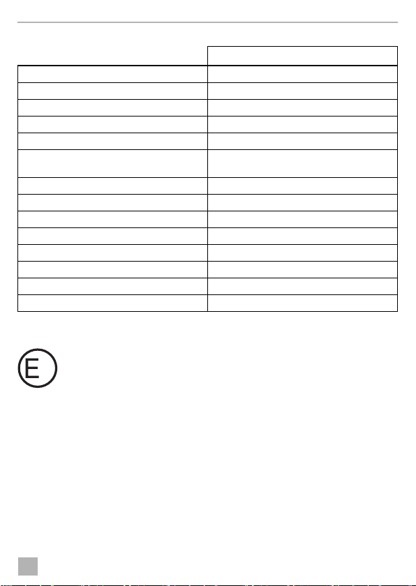
11 Technical data
M71L
Ref. no.: 9600011060
Typ e: Co lo r T FT L CD
Display size: 7" (17.8 cm)
Brightness: Approx. 500 cd/m²
Display resolution, H x V: 800 x 480 pixels
Viewing angle: vertical: above 50°, below 70°,
Television standard: PAL/NTSC (automatic switching)
Operating voltage: 12 – 32 Vg
Output: maximum 10 W
Operating temperature: –20 °C to +70 °C
Storage temperature: –30 °C to +80 °C
Vibration resistance: 6 g
Dimensions W x H x D: 174 x 125 x 26 mm
Weig ht: 40 0 g
Certifications
This device has E8 approval.
horizontal: right/left: 70°
19

Erklärung der Symbole PerfectView M71 L
DE
Bitte lesen Sie diese Anleitung vor Einbau und Inbetriebnahme sorgfältig durch und
bewahren Sie sie auf. Geben Sie sie im Falle einer Weitergabe des Produktes an den
Nutzer weiter.
Inhaltsverzeichnis
1 Erklärung der Symbole . . . . . . . . . . . . . . . . . . . . . . . . . . . . . . . . . . . . . . . . . . . . . . . . . . . . . .20
2 Sicherheits- und Einbauhinweise . . . . . . . . . . . . . . . . . . . . . . . . . . . . . . . . . . . . . . . . . . . . . . 21
3 Lieferumfang . . . . . . . . . . . . . . . . . . . . . . . . . . . . . . . . . . . . . . . . . . . . . . . . . . . . . . . . . . . . . . 23
4 Bestimmungsgemäßer Gebrauch . . . . . . . . . . . . . . . . . . . . . . . . . . . . . . . . . . . . . . . . . . . . .23
4 Bestimmungsgemäßer Gebrauch . . . . . . . . . . . . . . . . . . . . . . . . . . . . . . . . . . . . . . . . . . . . .23
5 Technische Beschreibung . . . . . . . . . . . . . . . . . . . . . . . . . . . . . . . . . . . . . . . . . . . . . . . . . . .24
6 LCD-Monitor montieren . . . . . . . . . . . . . . . . . . . . . . . . . . . . . . . . . . . . . . . . . . . . . . . . . . . . .24
7 LCD-Monitor benutzen. . . . . . . . . . . . . . . . . . . . . . . . . . . . . . . . . . . . . . . . . . . . . . . . . . . . . .28
8 LCD-Monitor pflegen und reinigen . . . . . . . . . . . . . . . . . . . . . . . . . . . . . . . . . . . . . . . . . . . .30
9 Gewährleistung . . . . . . . . . . . . . . . . . . . . . . . . . . . . . . . . . . . . . . . . . . . . . . . . . . . . . . . . . . .30
10 Entsorgung . . . . . . . . . . . . . . . . . . . . . . . . . . . . . . . . . . . . . . . . . . . . . . . . . . . . . . . . . . . . . . .30
11 Technische Daten . . . . . . . . . . . . . . . . . . . . . . . . . . . . . . . . . . . . . . . . . . . . . . . . . . . . . . . . . . 31
1 Erklärung der Symbole
VORSIC HT!
!
A
Sicherheitshinweis: Nichtbeachtung kann zu Verletzungen führen.
ACHTUNG!
Nichtbeachtung kann zu Materialschäden führen und die Funktion des Produktes
beeinträchtigen.
I
20
HINWEIS
Ergänzende Informationen zur Bedienung des Produktes.

PerfectView M71L Sicherheits- und Einbauhinweise
DE
2 Sicherheits- und Einbauhinweise
Beachten Sie die vom Fahrzeughersteller und vom Kfz-Handwerk vorgeschriebenen
Sicherheitshinweise und Auflagen!
Der Hersteller übernimmt in folgenden Fällen keine Haftung für Schäden:
•
Montage- oder Anschlussfehler
•
Beschädigungen am Produkt durch mechanische Einflüsse und falsche Anschlussspannung
•
Veränderungen am Produkt ohne ausdrückliche Genehmigung vom Hersteller
•
Verwendung für andere als die in der Anleitung beschriebenen Zwecke
ACHTUNG! Beschädigungsgefahr!
•
A
Beachten Sie deshalb folgende Hinweise:
•
Verwenden Sie bei Arbeiten an den folgenden Leitungen nur isolierte Kabelschuhe, Stecker
und Flachsteckhülsen:
•
Verwenden Sie eine Krimpzange (Abb. 1 12, Seite 3) zum Verbinden der Kabel.
•
Schrauben Sie das Kabel bei Anschlüssen an Leitung 31 (Masse)
Beim Abklemmen des Minuspols der Batterie verlieren alle flüchtigen Speicher der Komfortelektronik ihre gespeicherten Daten.
Klemmen Sie wegen der Kurzschlussgefahr vor Arbeiten an der Fahrzeugelektrik
immer den Minuspol ab.
Bei Fahrzeugen mit Zusatzbatterie müssen Sie an dieser ebenfalls den Minuspol
abklemmen.
•
Unzureichende Leitungsverbindungen können zur Folge haben, dass durch
Kurzschluss
– Kabelbrände entstehen,
– der Airbag ausgelöst wird,
– elektronische Steuerungseinrichtungen beschädigt werden,
– elektrische Funktionen ausfallen (Blinker, Bremslicht, Hupe, Zündung, Licht).
– 30 (Eingang von Batterie Plus direkt),
– 15 (Geschaltetes Plus, hinter Batterie),
– 31 (Rückleitung ab Batterie, Masse),
– 58 (Rückfahrscheinwerfer).
Verwen den S ie kein e Lüsterklemmen.
– mit Kabelschuh und Zahnscheibe an eine fahrzeugeigene Masseschraube oder
– mit Kabelschuh und Blechschraube an das Karosserieblech.
Achten Sie auf eine gute Masseübertragung!
21

Sicherheits- und Einbauhinweise PerfectView M71L
DE
•
Folgende Daten müssen Sie je nach Fahrzeugausstattung neu einstellen:
–Radiocode
–Fahrzeuguhr
– Zeitschaltuhr
– Bordcomputer
– Sitzposition
Hinweise zur Einstellung finden Sie in der jeweiligen Bedienungsanleitung.
Beachten Sie folgende Hinweise bei der Montag e:
VORSIC HT!
•
!
Beachten Sie folgende Hinweise bei der Arbeit an elektrischen Teilen:
•
Benutzen Sie zum Prüfen der Spannung in elektrischen Leitungen nur eine Diodenprüflampe
(Abb. 1 1, Seite 3) oder ein Voltmeter (Abb. 1 2, Seite 3).
Prüflampen mit einem Leuchtkörper (Abb. 1 3, Seite 3) nehmen zu hohe Ströme auf,
wodurch die Fahrzeugelektronik beschädigt werden kann.
•
Beachten Sie beim Verlegen der elektrischen Anschlüsse, dass diese
•
Isolieren Sie alle Verbindungen und Anschlüsse.
•
Sichern Sie die Kabel gegen mechanische Beanspruchung durch Kabelbinder oder
Isolierband, z. B. an vorhandenen Leitungen.
Beachten Sie folgende Hinweise beim Umgang mit dem LCD-Monitor:
!
Befestigen Sie den Monitor so, dass er sich unter keinen Umständen (scharfes
Abbremsen, Verkehrsunfall) lösen und zu Verletzungen der Fahrzeuginsassen
führen kann.
•
Befestigen Sie den Monitor nicht im Wirkungsbereich eines Airbags, da bei
Auslösung sonst Verletzungsgefahr besteht.
– nicht geknickt oder verdreht werden,
–nicht an Kanten scheuern,
– nicht ohne Schutz durch scharfkantige Durchführungen verlegt werden (Abb. 3, Seite 4).
VORSIC HT!
•
Personen (einschließlich Kinder), die aufgrund ihrer physischen, sensorischen oder
geistigen Fähigkeiten oder ihrer Unerfahrenheit oder Unkenntnis nicht in der Lage
sind, das Produkt sicher zu benutzen, sollten dieses Produkt nicht ohne Aufsicht
oder Anweisung durch eine verantwortliche Person nutzen.
•
Öffnen Sie den Monitor nicht (Abb. 4, Seite 4).
•
Tauchen Sie den Monitor keinesfalls in Wasser (Abb. 5, Seite 4); der Monitor ist
nicht wasserdicht.
•
Der Monitor darf auf keinen Fall die Sicht beim Autofahren behindern (Abb. 8,
Seite 5).
•
Bedienen Sie den Monitor nicht mit nassen Händen.
•
Nehmen Sie den Monitor außer Betrieb, wenn das Gehäuse beschädigt ist.
22

PerfectView M71 L Lieferumfang
DE
ACHTUNG!
•
A
Schließen Sie die korrekte Spannung an.
•
Benutzen Sie den Monitor nicht in Umgebungen, die
– direkter Sonnenstrahlung ausgesetzt sind,
– starken Temperaturschwankungen unterliegen,
– eine hohe Luftfeuchtigkeit aufweisen,
– eine schlechte Ventilation haben,
– staubig oder ölig sind.
•
Drücken Sie nicht auf das LCD-Display.
•
Lassen Sie den Monitor nicht fallen.
•
Wenn Sie den Monitor in Fahrzeugen einsetzen, sollte das Fahrzeug während des
Betriebs laufen, damit die Fahrzeugbatterie nicht entladen wird.
•
Die Bildqualität kann sich verschlechtern, wenn starke elektromagnetische Felder in
der Nähe sind.
Montieren Sie den Monitor deshalb nicht in der Nähe von Lautsprechern.
3Lieferumfang
Nr. in
Abb. 9,
Seite 5
1 1 Monitor 9600011060
2 1 Monitorhalter 9102200193
3 1 Abdeckung Monitorhalterung –
– 1 Anschlusskabel 9102200056
––Befestigungsmaterial –
Menge Bezeichnung Artikel-Nr.
4 Bestimmungsgemäßer Gebrauch
Der LCD-Monitor PerfectView M71L (Art.-Nr. 9600011060) ist vorrangig für den Einsatz in
Fahrzeugen gedacht. Er kann verwendet werden, um Kameras (z. B. Rückfahrvideosystem) oder
andere Videoquellen anzuschließen.
Der LCD-Monitor ist für den Einsatz in allen Fahrzeugen ausgelegt.
Der LCD-Monitor ist für den gewerblichen Einsatz geeignet.
23

Technische Beschreibung PerfectView M71L
DE
5 Technische Beschreibung
5.1 Funktionsbeschreibung
Der LCD-Monitor ist ein Monitor, an den Kameras (z. B. Rückfahrvideosystem) oder andere Videoquellen (z. B. DVD-Gerät) angeschlossen werden können. Zwischen den Videoquellen kann hinund hergeschaltet werden.
Der Monitor bietet Steuerleitungen, mit denen die K ameras automatisch aktiviert werden können.
Er kann bis zu vier Kameras betreiben, die über externe Steuerleitungen sowie auch manuell
aktiviert werden können. Der Monitor hat zusätzlich eine Abstandsanzeige im Display, die beim
Einlegen des Rückwärtsganges automatisch aktiviert wird (AV1).
5.2 Bedienelemente
Am Monitor finden Sie folgende Bedienelemente:
Nr. in
Abb. 0,
Seite 6
Beschreibung
1 Schaltet den Monitor ein und aus.
2 Schaltet in den Einstellmodus.
3 Der Lichtsensor passt die Helligkeit des Displays automatisch an das
4 – Verringert die Lautstärke oder den ausgewählten Parameter (Hellig-
5 + Erhöht die Lautstärke oder den ausgewählten Parameter (Helligkeit,
6 Wählt die Kamera aus.
7 Monitorhalterung
8Lautsprecher
Umgebungslicht an.
keit, Kontrast, Farbton).
Kontrast, Farbton).
6 LCD-Monitor montieren
6.1 Benötigtes Werkzeug (Abb. 1, Seite 3)
Für Einbau und Montage benötigen Sie folgende Werkzeuge:
•
Maßstab (4)
•
Körner (5)
•
Hammer (6)
24

PerfectView M71L LCD-Monitor montieren
DE
•
Satz Bohrer (7)
•
Bohrmaschine (8)
•
Schraubendreher (9)
Für den elektrischen Anschluss und seine Überprüfung benötigen Sie folgende Hilfsmittel:
•
Diodenprüflampe (1) oder Voltmeter (2)
•
Isolierband (10)
•
Wärmeschrumpfschlauch
•
Heißluftföhn (11)
•
Krimpzange (12)
•
Ggf. Lötkolben (13)
•
Ggf. Lötzinn (14)
•
Ggf. Kabeldurchführungstüllen
Zur Befestigung der Kabel benötigen Sie ggf. noch Kabelbinder.
6.2 Monitor montieren
VORSICHT! Verletzungsgefahr!
!
Beachten Sie folgende Hinweise bei der Montag e:
•
•
•
•
•
•
•
•
Wählen Sie den Platz des Monitors so aus, dass unter keinen Umständen (z. B. durch
scharfes Abbremsen, Verkehrsunfall) Fahrzeuginsassen verletzt werden können.
Wählen Sie einen geeigneten Montageort, so dass Sie ungehinderte Sicht auf den Monitor
haben (Abb. 6 und Abb. 7, Seite 4).
Montieren Sie den Monitor niemals im Kopfaufschlagbereich oder im Wirkungsbereich eines
Airbags. Bei Auslösung besteht sonst Verletzungsgefahr.
Der Monitor darf auf keinen Fall die Sicht beim Autofahren behindern (Abb. 8, Seite 5).
Der Montageort sollte eben sein.
Kontrollieren Sie, ob unterhalb des gewählten Montageortes der benötigte Freiraum zum
Anbringen von Scheiben und Muttern zur Verfügung steht.
Kontrollieren Sie vorher, ob ausreichender Freiraum für den Bohreraustritt vorhanden ist
(Abb. 2, Seite 4).
Bedenken Sie das Gewicht des Monitors. Sehen Sie ggf. Verstärkungen (größere Unterleg-
scheiben oder Platten) vor.
Stellen Sie sicher, dass Sie den Anschl usskabel zum Monitor verlegen können.
25

LCD-Monitor montieren PerfectView M71L
DE
Montageort festlegen (Abb. a, Seite 7)
➤ Setzen Sie den Monitor auf den Monitorhalter.
➤ Platzieren Sie den Monitor mit dem angebrachten Halterfuß probeweise.
➤ Zeichnen Sie die Umrisse des Halterfußes auf das Armaturenbrett.
➤ Nehmen Sie den Monitor vom Monitorhalter ab.
Monitorhalter an Armaturenbrett schrauben (Abb. b, Seite 7)
➤ Halten Sie den Halterfuß innerhalb der zuvor gezeichneten Umrisse.
➤ Befestigen Sie den Monitorhalter mit geeigneten Schrauben.
Monitor befestigen
➤ Setzen Sie den Monitor auf den Monitorhalter und fixieren Sie ihn mit der Rändelmutter
(Abb. a, Seite 7).
6.3 Monitor elektrisch anschließen
Den Schaltplan für den LCD-Monitor finden Sie in Abb. d, Seite 8.
Nr. Bezeichnung
1Monitor
220-polige Buchse
3 Monitorzuleitung
420-poliger Stecker
5 12 – 24-V-Plus-Kabel (rot): Anschluss an den Pluspol der Zündung
6 Massekabel (schwarz): Anschluss an den Minuspol der Spannungsquelle
7 Kabel (grün): Steuereingang für Videoeingang AV1,
8 Kabel (weiß): Steuereingang für Videoeingang AV2,
9 6-polige Buchse AV1 (Anschluss an Videoquelle 1)
10 6-polige Buchse AV2 (Anschluss an Videoquelle 2)
11 6-polige Buchse AV3 (Anschluss an Videoquelle 3)
12 6-polige Buchse AV4 (Anschluss an Videoquelle 4,
13 Kabel (blau): Steuereingang für Videoeingang AV3
(geschaltetes Plus, Klemme 15) oder den Pluspol der Batterie (Klemme 30)
z. B. für den Anschluss an den Rückfahrscheinwerfer
z. B. Seitenkamera
mit Videosignalerkennung)
26

PerfectView M71L LCD-Monitor montieren
DE
ACHTUNG!
A
Beachten Sie folgende Hinweise bei der Verlegung der Anschlusskabel:
•
•
•
•
Monitor als Rückfahrvideosystem anschließen (Abb. d, Seite 8)
➤ Verlegen Sie das Anschlusskabel des Monitorhalters am Armaturenbrett.
➤ Stecken Sie den Stecker des Monitorkabels (2) in die Buchse (4) des Anschlusskabels (3).
A
➤ Schließen Sie das rote und schwarze Kabel des Anschlusskabels an eine geeignete
➤ Wenn der Monitor beim Einlegen des Rückwärtsganges aktiviert werden soll, schließen Sie
Nicht fachgerechte Kabelverlegungen und Kabelverbindungen führen immer wieder
zu Fehlfunktionen oder Beschädigungen von Bauteilen.
Eine korrekte Kabelverlegung und Kabelverbindung ist die Grundvoraussetzung für
eine dauerhafte und fehlerfreie Funktion der nachgerüsteten Komponenten.
Verwenden Sie für die Durchführung der Anschlusskabel nach Möglichkeit Originaldurchführungen oder andere Durchführungsmöglichkeiten, z. B. Lüftungsgitter. Wenn keine
Durchführungen vorhanden sind, müssen Sie ein Loch von ∅ 22 mm bohren. Schauen Sie
vorher nach, ob ausreichender Freiraum für den Bohreraustritt vorhanden ist (Abb. 2, Seite 4).
Decken Sie die Bohrung mit der Durchführung (Abb. b 1, Seite 7) in der Bodenplatte des
Monitorhalters ab.
Um Beschädigungen am Kabel zu vermeiden, halten Sie beim Verlegen der Kabel immer
ausreichend Abstand zu heißen Fahrzeugteilen (Leuchten, Heizung, Lüftern usw.).
Beachten Sie beim Verlegen der Kabel (Abb. 3, Seite 4), dass diese
– nicht stark geknickt oder verdreht werden,
–nicht an Kanten scheuern,
– nicht ohne Schutz durch scharfkantige Durchführungen verlegt werden.
Der Stecker muss hörbar einrasten.
ACHTUNG! Beschädigungsgefahr!
Achten Sie beim Anschluss an die Spannungsquelle auf die richtige Polung.
Spannungsquelle an:
– Schließen Sie das rote Kabel (5) an Klemme 15 (Zündung) an.
– Schließen Sie das schwarze Kabel (6) an Klemme 31 (Masse) an.
das grüne Kabel (7) an die Plusleitung des Rückfahrscheinwerfers an.
HINWEIS
I
➤ Wenn der Monitor z. B. beim Betätigen des Blinkers aktiviert werden soll, schließen Sie
Wenn am grünen Kabel (7) Spannung anliegt, wird die Rückfahrkamera aktiviert.
Die Rückfahrkamera hat Vorrang.
folgendes Steuerkabel an eine Plusleitung der Blinker an:
–weißes Kabel (8), blaues Kabel (13)
27

LCD-Monitor benutzen PerfectView M71 L
DE
HINWEIS
I
Dieses Steuerkabel dient als Signalleitung zur Akti vierung z. B. einer Seitenkamera bei Betätigung
der Blinker.
➤ Verbinden Sie ggf. die Buchse AV1 (9) des Anschlusskabels mit dem Stecker der Videoquelle 1
➤ Verbinden Sie ggf. die Buchse AV2 (10) des Anschlusskabels mit dem Stecker der
➤ Verbinden Sie ggf. die Buchse AV3 (11) des Anschlusskabels mit dem Stecker der
I
Anschluss einer zusätzlichen Rückfahrkamera (Anhängerbetrieb)
➤ Verbinden Sie ggf. die Buchse AV4 (12) des Anschlusskabels mit dem Stecker der zusätzlichen
Wenn an diesem Steuerkabel Spannung anliegt, werden die Videoeingänge AV2 und
AV3 aktiviert.
(z. B. Rückfahrkamera).
Videoquelle 2 (z. B. Seitenkamera).
Videoquelle 3 (z. B. Kamera).
HINWEIS
Beachten Sie die Stromaufnahme des Videosystems. Die Kameras sin d mit Heizungen
ausgestattet. Es kann maximal ein Strom von 1,5 A fließen (drei Kameras im Heizbetrieb). Verwenden Sie bei direktem Anschluss an die Batterie einen Trennschalter.
Damit können Sie das Videosystem leicht von der Batterie trennen, wenn Sie das
Fahrzeug länger nicht verwenden.
Rückfahrkamera.
7 LCD-Monitor benutzen
7.1 Monitor einschalten
➤ Drücken Sie bei abgeschaltetem Monitor die Taste (Abb. 0 2, Seite 6), um den Monitor
einzuschalten.
➤ Die Taste leuchtet blau.
✓ Das übertragene Bild erscheint.
7.2 Monitor ausschalten
➤ Drücken Sie die Taste (Abb. 0 2, Seite 6), um den Monitor auszuschalten.
➤ Die Taste leuchtet rot.
✓ Das Bild erlischt.
28

PerfectView M71L LCD-Monitor benutzen
DE
7.3 Monitor einstellen
Sie können den Monitor Ihren Wünschen entsprechend wie folgt einstellen (Abb. 0, Seite 6):
➤ Drücken Sie die Taste „ “ (5), um die gewünschten Parameter auszuwählen.
✓ Die einstellbaren Parameter werden in der folgenden Reihenfolge angezeigt:
– Helligkeit („Brightness“): 0 – 100
– Kontrast („Contrast“): 0 – 100
– Sättigung („Saturation“): 0 – 100
– Lautstärke („Volume“): 0 – 100
– Sprache („Language“): „Englisch“, „Französisch“, „Deutsch“
– Spiegelung AV1/AV2/AV3/AV4 („Mirror AV1/AV2/AV3/AV4“): „Ja“ oder „Nein“
– Video AV1/AV2/AV3/AV4 („Video AV1/AV2/AV3/AV4“): „Ja“ oder „Nein“
– Abstandsanzeige („Distance Grid“): „EIN“ oder „AUS“
– Anhängererkennung („Trailer Detection“): „EIN“ oder „AUS“
– Tag-/Nachtmodus („Day/Night“): „EIN“ oder „AUS“
– Zurücksetzen („Default“): Werkeinstellung aller Parameter
➤ Drücken Sie die Taste „+“ (3) oder Taste „–“ (4), um den gewünschten Parameter einzustellen.
➤ Drücken Sie die Taste „+“ (3), um den Wert des ausgewählten Parameters zu erhöhen.
➤ Drücken Sie die Taste „–“ (4), um den Wert des ausgewählten Parameters zu verringern.
7.4 Videoquelle einstellen
Gehen Sie wie folgt vor, um die Videoquelle einstellen (Abb. 0, Seite 6):
➤ Wenn Sie die Videoquelle umschalten möchten, drücken Sie die Taste (6).
✓ Der Monitor wechselt die Kamera in der Reihenfolge „Kamera 1 – Kamera 2 – Kamera 3 –
Kamera 4“.
Mit dem Parameter „Video AV1/AV2/AV3/AV4“ können nicht benutzte Videoeingänge inaktiv
geschaltet werden. Diese leeren Eingänge werden dann übersprungen.
7.5 Anhängerkamera erkennen
Diese Funktion wird bei Einsatz einer Anhängerkamera benötigt (Abb. c, Seite 7), wenn das
System automatisch über den Rückwärtsgang aktiviert wird.
•
Eine Kamera angeschlossen (z. B. Zugmaschine ohne Anhänger):
die an AV1 angeschlossene Kamera (1) wird aktiviert
•
Zwei Kameras angeschlossen (z. B. Zugmaschine mit Anhänger):
die an AV4 angeschlossene Kamera (2) wird aktiviert (AV1 ist inaktiv).
29

LCD-Monitor pflegen und reinigen PerfectView M71L
DE
8 LCD-Monitor pflegen und reinigen
ACHTUNG! Beschädigungsgefahr!
•
A
➤ Reinigen Sie den Monitor gelegentlich mit einem feuchten, weichen Tuch.
Keine scharfen oder harten Mittel zur Reinigung verwenden, da dies zu einer
Beschädigung des Monitors führen kann.
•
Entfernen Sie die Kabel, bevor Sie den Monitor reinigen, damit es nicht zu einem
Kurzschluss kommen kann.
9Gewährleistung
Es gilt die gesetzliche Gewährleistungsfrist. Sollte das Produkt defekt sein, wenden Sie sich bitte
an die Niederlassung des Herstellers in Ihrem Land (Adressen siehe Rückseite der Anleitung) oder
an Ihren Fachhändler.
Zur Reparatur- bzw. Gewährleistungsbearbeitung müssen Sie Folgendes einschicken:
•
defekte Komponenten,
•
eine Kopie der Rechnung mit Kaufdatum,
•
einen Reklamationsgrund oder eine Fehlerbeschreibung.
10 Entsorgung
➤ Geben Sie das Verpackungsmaterial möglichst in den entsprechenden Recycling-Müll.
Wenn Sie das Produkt endgültig außer Betrieb nehmen, informieren Sie sich bitte beim
nächsten Recyclingcenter oder bei Ihrem Fachhändler über die zutreffenden
M
Entsorgungsvorschriften.
30
 Loading...