

Dometic PERFECTVIEW CAM45 Installation And Operating Manual
CAM45
ENDEFRESPTITNLDASV
NOFIRUPLSKCSHU
DRIVING SUPPORT
PERFECTVIEW
Peruutusvideokamera
Asennus- ja käyttöohje. . . . . . . . . . . . . . .115
Видеокамера заднего вида
Инструкция по монтажу
и эксплуатации. . . . . . . . . . . . . . . . . . . . 126
Kamera cofania
Instrukcja montażu i obsługi . . . . . . . . . 137
Cúvacia kamera
Návod na montáž a uvedenie
do prevádzky . . . . . . . . . . . . . . . . . . . . . 148
Rear View Video Camera
Installation and Operating Manual . . . . . . 9
Rückfahrvideokamera
Montage- und Bedienungsanleitung . . . 20
Caméra vidéo de recul
Instructions de montage et de service . . 31
Cámara de vídeo de marcha atrás
Instrucciones de montaje y de uso . . . . . 42
Câmara de marcha-atrás
Instruções de montagem e manual de
instruções . . . . . . . . . . . . . . . . . . . . . . . . . 53
Videocamera per la retromarcia
Istruzioni di montaggio e d’uso . . . . . . . .63
Achteruitrijvideocamera
Montagehandleiding en
gebruiksaanwijzing. . . . . . . . . . . . . . . . . . 74
Bakvideokamera
Monterings- og betjeningsvejledning. . . 85
Couvací kamera
Návod k montáži a obsluze . . . . . . . . . . 158
Tolat ó k a m e r a
Szerelési és használati útmutató . . . . . . 168
Backningsvideokamera
Monterings- och bruksanvisning . . . . . . . 95
Ryggevideokamera
Monterings- og bruksanvisning . . . . . . . 105

1 2
3
4
7 8 9
5
6
10 11 12
1
CAM45
3
CAM45
2
3
4
5
6
7
4
CAM45
1
3 4
2
8
3
2
1
9
5
CAM45
90°
0
a
1.
2.
b
c
d
e
6
CAM45
~50°
f
AB
1.
2.
1.
g
h
A
B
i
7
CAM45
1.
2.
j
8

CAM45
EN
Please read this instruction manual carefully before installation and first use, and store
it in a safe place. If you pass on the product to another person, hand over this instruction manual along with it.
Table of contents
1 Explanation of symbols. . . . . . . . . . . . . . . . . . . . . . . . . . . . . . . . . . . . . . . . . . . . . . . . . . . . . . 10
2 Safety and installation instructions . . . . . . . . . . . . . . . . . . . . . . . . . . . . . . . . . . . . . . . . . . . . . 10
3 Scope of delivery . . . . . . . . . . . . . . . . . . . . . . . . . . . . . . . . . . . . . . . . . . . . . . . . . . . . . . . . . . 12
4 Intended use . . . . . . . . . . . . . . . . . . . . . . . . . . . . . . . . . . . . . . . . . . . . . . . . . . . . . . . . . . . . . . 12
5 Technical description . . . . . . . . . . . . . . . . . . . . . . . . . . . . . . . . . . . . . . . . . . . . . . . . . . . . . . . 13
6 Information on electrical connection. . . . . . . . . . . . . . . . . . . . . . . . . . . . . . . . . . . . . . . . . . . 13
7 Fitting the camera . . . . . . . . . . . . . . . . . . . . . . . . . . . . . . . . . . . . . . . . . . . . . . . . . . . . . . . . . . 14
8 Cleaning and caring for the camera. . . . . . . . . . . . . . . . . . . . . . . . . . . . . . . . . . . . . . . . . . . . 17
9 Warranty . . . . . . . . . . . . . . . . . . . . . . . . . . . . . . . . . . . . . . . . . . . . . . . . . . . . . . . . . . . . . . . . . 18
10 Disposal. . . . . . . . . . . . . . . . . . . . . . . . . . . . . . . . . . . . . . . . . . . . . . . . . . . . . . . . . . . . . . . . . . 18
11 Technical data. . . . . . . . . . . . . . . . . . . . . . . . . . . . . . . . . . . . . . . . . . . . . . . . . . . . . . . . . . . . . 19
9

Explanation of symbols CAM45
EN
1 Explanation of symbols
WARNING!
!
!
A
I
Safety instruction: Failure to observe this instruction can cause fatal or serious injury.
CAUTION!
Safety instruction: Failure to observe this instruction can lead to injury.
NOTICE!
Failure to observe this instruction can cause material damage and impair the function
of the product.
NOTE
Supplementary information for operating the product.
2 Safety and installation instructions
Please observe the prescribed safety instructions and stipulations from the vehicle
manufacturer and service workshops.
The manufacturer accepts no liability for damage in the following cases:
•
Faulty assembly or connection
•
Damage to the product resulting from mechanical influences and excess voltage
•
Alterations to the product without express permission from the manufacturer
•
Use for purposes other than those described in the operating manual
Please note the following:
•
To prevent the risk of short circuits, always disconnect the negative terminal of the vehicle's
electrical system before working on it.
If the vehicle has an additional battery, its negative terminal should also be disconnected.
•
Inadequate supply cable connections could result in short circuits, causing:
–Cable fires
– The airbag being triggered
– Damage to electronic control equipment
– Electrical malfunctions (indicators, brake light, horn, ignition, lights)
•
When working on the following cables, only use insulated cable terminals, plugs and flat
sockets:
– 30 (direct supply from positive battery terminal)
–15 (connected positive terminal, behind the battery)
– 31 (return cable from the battery, earth)
– 58 (reversing light)
Do not use porcelain wire connectors.
10

CAM45 Safety and installation instructions
EN
•
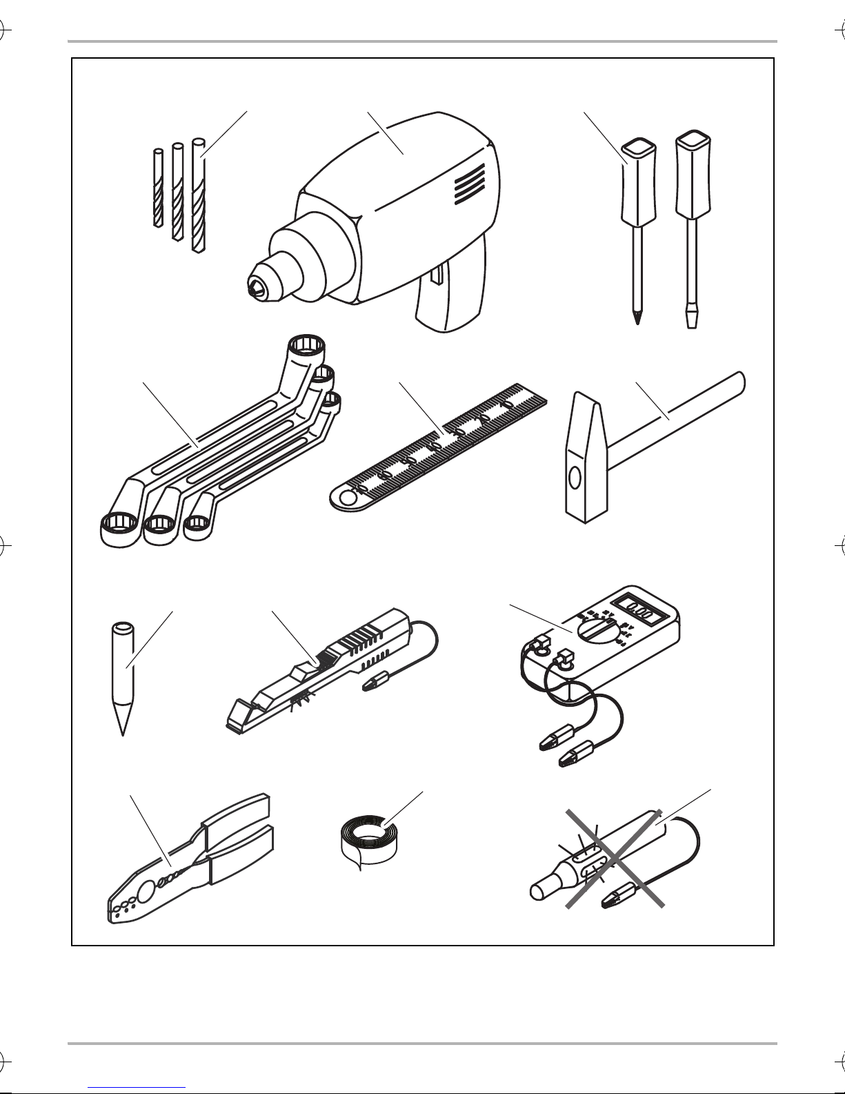
Use a crimping tool (fig. 1 10, page 3) to connect the cables.
•
Screw the cable when connecting cable 31 (earth).
– Screw on the cable using a cable terminal and serrated washer to one of the vehicle's earth
bolts or
– screw the cable to the bodywork using a cable terminal and a self-tapping screw.
Make sure there is a good earth connection.
If you disconnect the negative terminal of the battery, all data stored in the volatile memories will
be lost.
•
The following data must be reset, depending on the vehicle equipment options:
–Radio code
– Vehicle clock
–Timer
– On-board computer
– Seat position
You can find instructions for making these settings in the operating manual.
Observe the following installation instructions:
•
Secure the parts of the camera which are installed in the vehicle in such a way that they cannot
become loose under any circumstances (sudden braking, accidents) and cause injuries to the
occupants of the vehicle.
•
Secure any parts of the system concealed by the bodywork in such a manner that they cannot
be come loose or damage other parts or cables, or impair vehicle functions (steering, pedals,
etc.).
•
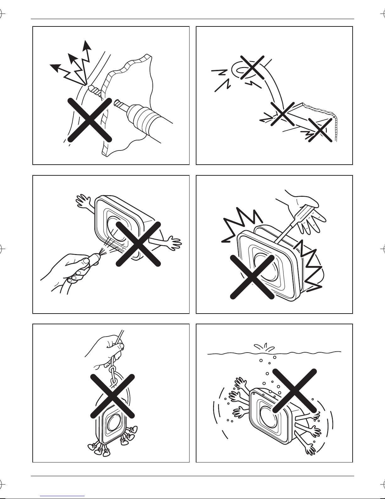
To prevent damage when drilling, make sure there is sufficient space on the other side for the
drill head to come out (fig. 2, page 4).
•
Deburr all drill holes and treat them with a rust-protection agent.
•
Always follow the safety instructions of the vehicle manufacturer.
Some work (e.g. on retention systems such as the AIRBAG etc.) may only be performed by
qualified specialists.
Observe the following instructions when working with electrical parts:
•
When testing the voltage in electrical cables, only use a diode test lamp (fig. 1 8, page 3) or
a voltmeter (fig. 1 9, page 3).
Test lamps with a bulb (fig. 1 12, page 3) consume voltages which are too high and can
damage the vehicle's electronic system.
•
When making electrical connections, (fig. 3, page 4), ensure that:
– they are not kinked or twisted
– they do not rub on edges
– they are not laid in sharp-edged ducts without protection.
•
Insulate all connections.
11

Scope of delivery CAM45
EN
•
Secure the cables against mechanical wear by using cable binders or insulating tape,
for example on existing cables.
The camera is watertight. However, the seals on the camera cannot withstand a high-pressure
cleaner (fig. 4, page 4). Therefore, you should observe the following instructions when handling
the camera:
•
People (including children) whose physical, sensory or mental capacities or whose lack of
experience or knowledge prevent them from using this product safely should not use it without
the supervision or instruction of a responsible person.
•
Do not open the camera, as this impairs the leak tightness and the function of the camera
(fig. 5, page 4).
•
Do not pull at the cables, as this impairs the tightness and the function of the camera (fig. 6,
page 4).
•
The camera is not suitable for use under water (fig. 7, page 4)!
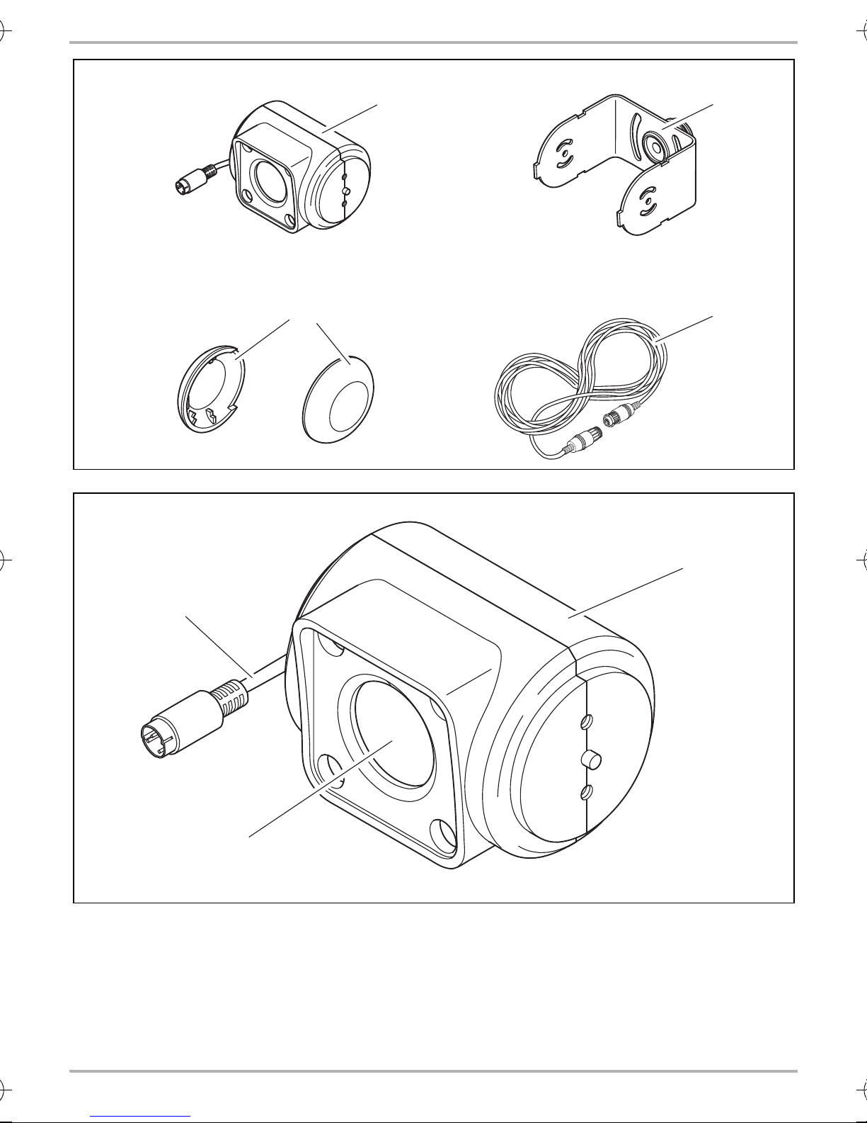
3Scope of delivery
No. in
fig. 8, page 5
1 1 Camera 9600000523
21Camera bracket
32Side cover –
4 1 System cable 9102200141
–1Fastening material –
– 1 Installation and operating manual –
Quantity Description Ref. no.
9600000571
with bushing sleeve
4Intended use
The CAM45 camera (ref. no. 9600000523) is designed primarily for use in vehicles. It can be used
in video systems to observe the space around the vehicle from the driver's seat when, for example
manoeuvring or parking.
WARNING!
!
Danger of personal injury by vehicle.
Reversing video systems are designed merely as an additional aid for reversing,
however this does not relieve you of the duty to take proper care when
reversing.
12

CAM45 Technical description
EN
5 Technical description
The camera with integrated microphone, which is encased in an aluminium housing, transmits
image and sound to a monitor via a cable. The infrared LEDs improve night vision.
The camera transmits the image as if you were looking in the rear-view mirror.
The camera consists of the following elements:
No. in
fig. 9, page 5
16-pin connection cable
2 Infrared LEDs
3 Microphone (rear side)
Description
6 Information on electrical connection
6.1 Laying cables
NOTICE! Beware of damage
•
A
When drilling holes, check beforehand that there is sufficient space on the other
side for the drill head to come out.
•
Cables and connections that are not properly installed will cause malfunctions or
damage to components. Correct installation of cables and connections ensures
lasting and trouble-free operation of the retrofitted components.
•
The cables may not be exposed for long periods to solvents such as benzene, since
solvents can damage the cable.
Therefore, please observe the following instructions:
•
As far as possible, use original ducts for laying the cables, or other suitable options such as
panelling edges, ventilation grilles or dummy plugs. If no openings are available, you must drill
holes for the cables. Check beforehand that there is sufficient space on the other side for the
drill head to emerge.
•
Wherever possible, lay cables inside the vehicle, as they are better protected there than
outside.
If you do need to lay a cable outside the vehicle, ensure that it is well fastened (use additional
cable ties, insulating tape etc.).
•
To prevent damage to the cables when laying them, ensure that they are far enough away from
hot or moving vehicle components (exhaust pipes, drive shafts, light systems, fans, heaters,
etc.). Use corrugated piping or other protective materials to protect against mechanical wear.
•
Screw on the plug connections for the connecting cables to protect them against water
penetration (fig. g, page 7).
13

Fitting the camera CAM45
EN
•
When laying the cables (fig. 3, page 4), make sure:
– they are not kinked or twisted
– they do not rub on edges
– they are not routed in sharp-edged ducts without protection.
•
Attach the cables securely in the vehicles to prevent tripping hazards. This can be performed by
using cable binders, insulating tape or gluing in place with adhesives.
•
Protect every through-hole made in the bodywork against water penetration, e.g. by using a
cable with a sealant and by spraying the cable and the cable sleeve with sealant.
NOTE
I
Only start sealing through-holes when you have completed all installation work on the
camera and have laid the required cable lengths.
7 Fitting the camera
7.1 Tools required
For installation and assembly, you will need the following tools:
•
Drill bit set (fig. 1 1, page 3)
•
Electric drill (fig. 1 2, page 3)
•
Screwdriver (fig. 1 3, page 3)
•
Set of ring or open-ended spanners (fig. 1 4, page 3)
•
Measuring ruler (fig. 1 5, page 3)
•
Hammer (fig. 1 6, page 3)
•
Centre punch (fig. 1 7, page 3)
To establish and test the electrical connection, the following tools are required:
•
Diode test lamp (fig. 1 8, page 3) or voltmeter (fig. 1 9, page 3)
•
Insulating tape (fig. 1 11, page 3)
•
Cable bushing sleeves (optional)
To fasten the cables you may require additional cable binders.
14

CAM45 Fitting the camera
EN
7.2 Fitting the camera
CAUTION!
!
I
Observe the following installation instructions:
•
To provide a suitable viewing angle, the camera must be attached at a height of at least 2 m.
Ensure that you have a firm place from which to work when mounting the camera.
•
Make sure that the installation location of the camera is sufficiently firm (e.g. to prevent the
camera from being knocked down by branches that may brush the roof of the vehicle).
Select a location for the camera and attach it firmly enough so that it cannot under any
circumstances fall off and injure bystanders (e.g. by being knocked off by branches
brushing over the roof of the vehicle).
NOTE
If installing the camera alters the vehicle height or the length specified in the vehicle
documents, your vehicle must be inspected by the appropriate authorities.
This authority must note any such changes your vehicle documents.
•
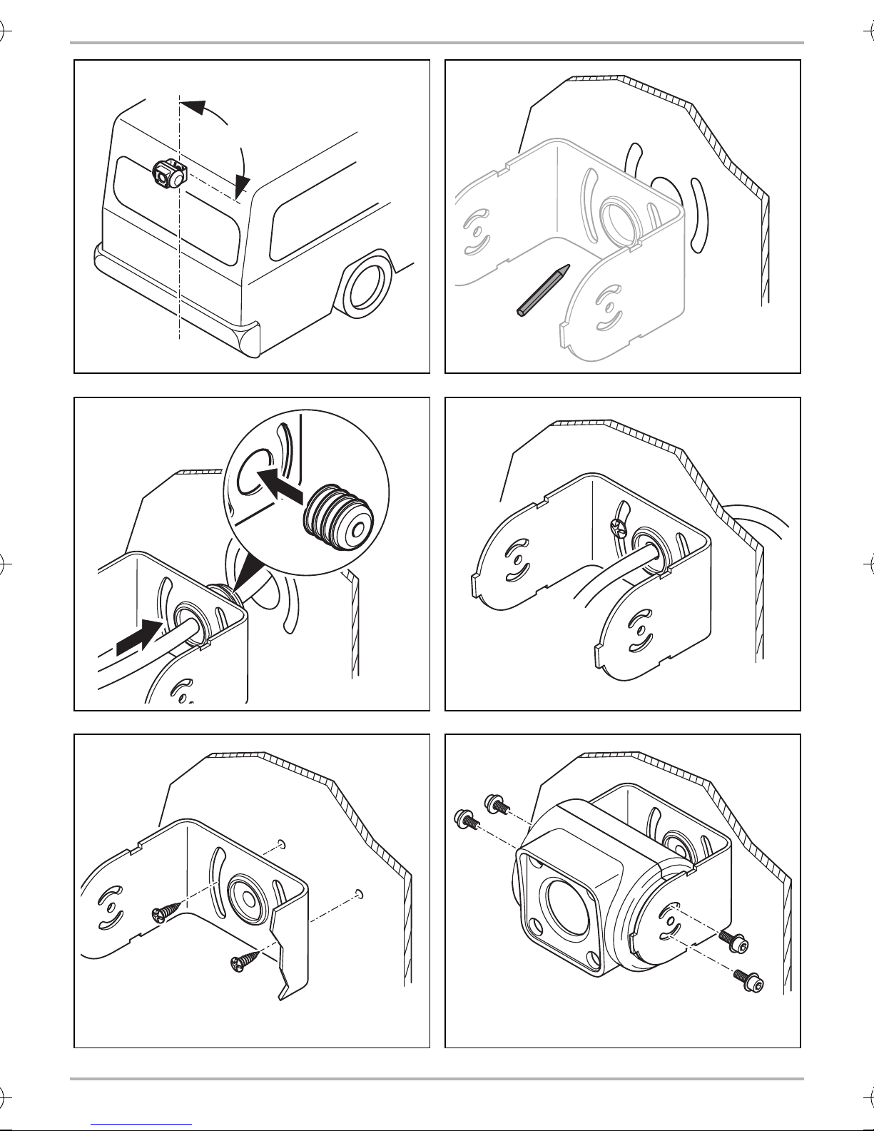
Mount the camera bracket horizontally and in the middle of the rear of the vehicle (fig. 0,
page 6).
•
The most secure type of attachment is with screws fitted through the body (not included in
scope of delivery). Please observe the following instructions:
– There must be sufficient space behind the chosen installation location to be able to carry
out the mounting procedure.
– Suitable measures must be taken to prevent water penetrating through any holes made
(e.g. by using screws and sealant and/or spraying the outer attachment parts with sealant).
– The location on the body where you wish to attach the camera must be rigid enough to
allow the camera to be tightly fastened.
•
Check beforehand that there is sufficient space on the other side for the drill head to come out
(fig. 2, page 4).
•
If you are not sure about the location you have chosen, ask your vehicle manufacturer or dealer.
NOTE
I
To perform the installation, proceed as follows:
We recommend greasing the threads of the bolts to prevent corrosion.
➤ Hold the camera at the chosen location and mark at least two different points for the drill holes
and the duct for the connection cable (fig. a, page 6).
➤ Using a hammer and centre punch, gently pre-punch the previously marked points to prevent
the drill head from slipping off.
15

Fitting the camera CAM45
EN
Creating a through-hole for the camera connection cable (fig. b, page 6)
NOTE
I
A
➤ Drill a hole with a Ø 16 mm at the previously marked duct.
➤ Deburr all drill holes that have been made in the sheet metal and apply rust-protection.
Screw on camera using self-tapping screws (fig. c, page 6)
A
If possible, use available openings, such as ventilation grilles, to feed the connection
cables through. If there are no existing ducts, you must drill a hole of Ø 16 mm.
NOTICE! Beware of damage
Check beforehand that there is sufficient space on the other side for the drill head to
come out.
NOTICE! Beware of damage
Self-tapping screws may only be fastened to steel metal with a minimum thickness of
1.5 mm.
➤ Drill the holes, with a Ø of 4 mm, at each of the markings.
➤ Deburr all drill holes and apply rust-protection.
➤ Screw on the camera bracket using 5 x 20 mm self-tapping screws.
Fitting the camera
NOTICE! Beware of damage
A
➤ Guide the camera cable into the vehicle interior.
➤ Slide the camera into the camera bracket.
➤ Fasten the camera loosely using the two screws M3 x 6 mm in the slots (fig. e, page 6).
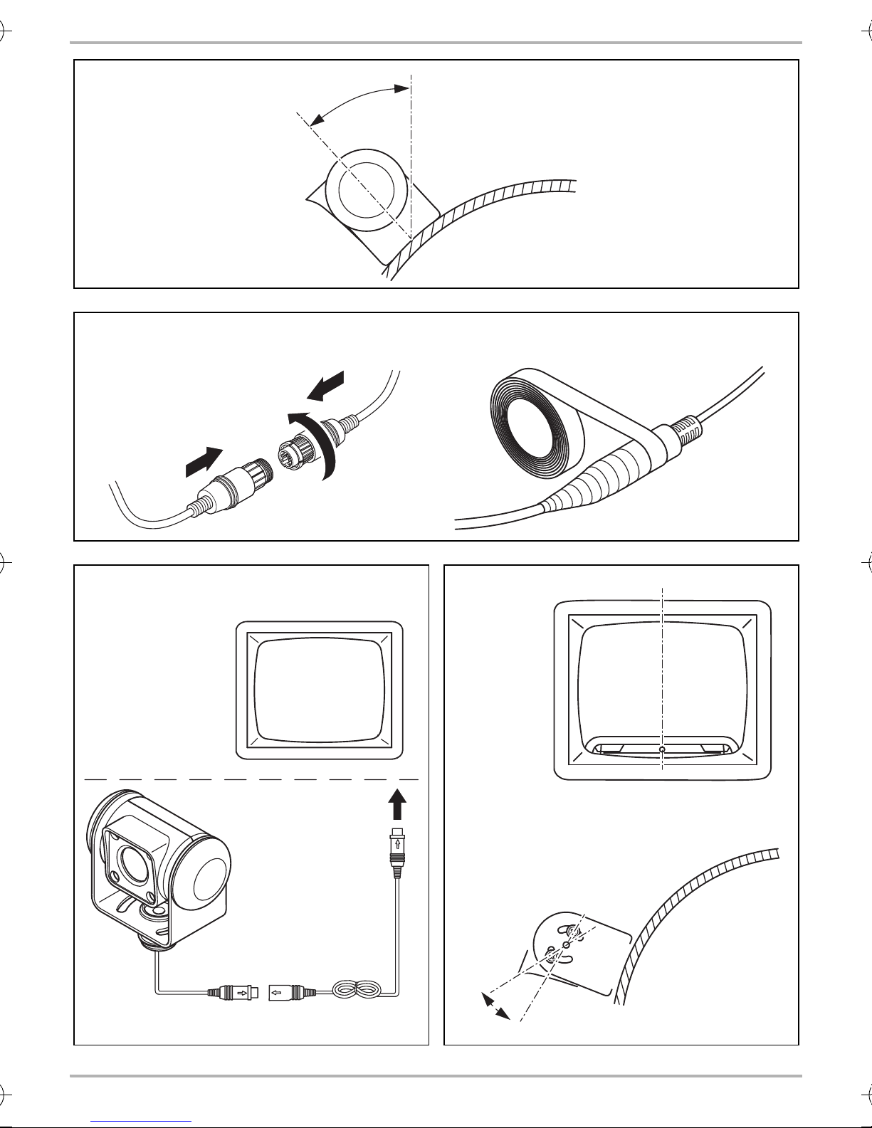
➤ Provisionally align the camera, so that the lens is at an angle of approx. 50° to the vertical axis
of the vehicle (fig. f, page 7).
Only use the screws supplied to mount the camera. Longer screws will damage the
camera.
16

CAM45 Cleaning and caring for the camera
EN
Establishing the electrical connection for the camera
NOTE
•
I
➤ Insert the camera cable plug into the socket for the extension cable.
➤ Screw on the plug connection of the connecting cables to protect against water penetration
(fig. g, page 7).
Aligning the camera
I
Lay the camera cable so that, should you need to remove the camera, you can
access the plug connection between the
camera and the extension cable easily. This greatly facilitates the disassembly.
•
To minimise corrosion in the plug, apply a small amount of grease, such as pin
grease, in one of the plugs.
NOTE
To do this you must first install and electrically connect a monitor (see schematic
connection diagram fig. h, page 7).
➤ Align the camera using the image on the monitor to help you:
The monitor image should show the rear or the bumper of the vehicle at the bottom edge of
the screen. The middle of the bumper should be in the middle of the screen (fig. i, page 7).
➤ Check the function of the camera after you have connected it to a monitor.
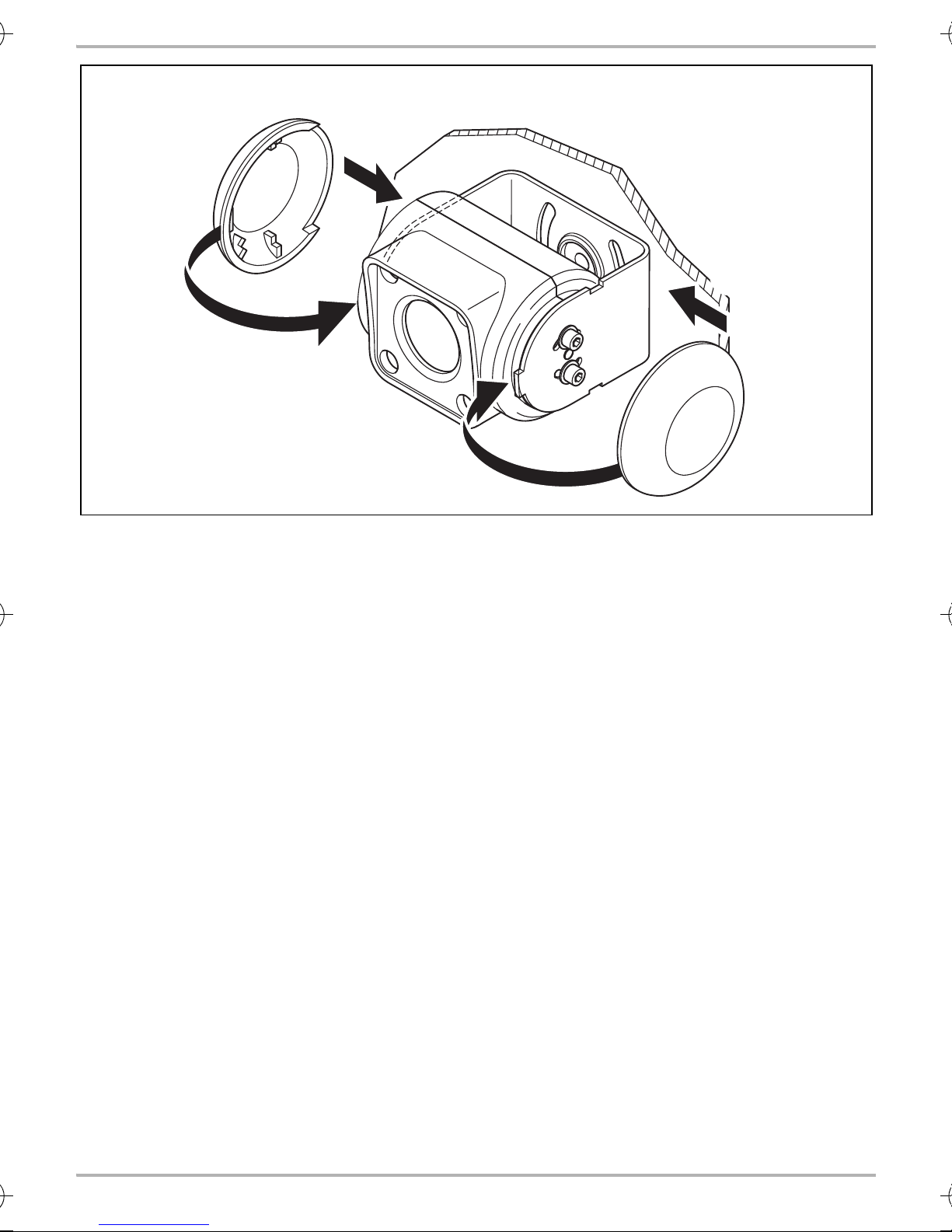
Fastening the camera
➤ Tighten the two fastening screws in the slots on the monitor bracket.
➤ Fit side covers into place (fig. j, page 8).
8 Cleaning and caring for the camera
NOTICE! Beware of damage
A
➤ Clean the camera with a soft, damp cloth from time to time.
Do not use any sharp or hard objects for cleaning since they may damage the device.
17

Warranty CAM45
EN
9Warranty
The statutory warranty period applies. If the product is defective, please contact the
manufacturer's branch in your country (see the back of the instruction manual for the addresses) or
your retailer.
For repair and guarantee processing, please send the following items:
•
Defect components
•
A copy of the receipt with purchasing date
•
A reason for the claim or description of the fault
10 Disposal
➤ Place the packaging material in the appropriate recycling waste bins wherever possible.
If you wish to finally dispose of the product, ask your local recycling centre or specialist
dealer for details about how to do this in accordance with the applicable disposal
M
regulations.
18

CAM45 Technical data
EN
9
11 Technical data
PerfectView CAM 45
Ref. no.: 9600000523
Image sensor: 1/4" CCD
Pixels: Approx. 250000 pixels
Video standard: PAL, 1 Vpp
Sensitivity: < 1 Lux / 0 Lux with infrared LEDs
Viewing angle: Approx. 120° diagonal
Approx. 80° horizontal
Approx. 65° vertical
Operating voltage: 11 to 16 Vg
Consumption: 1.2 W
Operating temperature: –20 °C to +70 °C
Protection class: IP69k
Vibration resistance: 6g
Dimensions W x H x D
(with bracket):
Weight: Approx. 0.18 kg
Certification:
78 x 60 x 50 mm
19

CAM45
DE
Bitte lesen Sie diese Anleitung vor Einbau und Inbetriebnahme sorgfältig durch und
bewahren Sie sie auf. Geben Sie sie im Falle einer Weitergabe des Produktes an den
Nutzer weiter.
Inhaltsverzeichnis
1 Erklärung der Symbole . . . . . . . . . . . . . . . . . . . . . . . . . . . . . . . . . . . . . . . . . . . . . . . . . . . . . . 21
2 Sicherheits- und Einbauhinweise. . . . . . . . . . . . . . . . . . . . . . . . . . . . . . . . . . . . . . . . . . . . . . 21
3 Lieferumfang . . . . . . . . . . . . . . . . . . . . . . . . . . . . . . . . . . . . . . . . . . . . . . . . . . . . . . . . . . . . . .23
4 Bestimmungsgemäßer Gebrauch . . . . . . . . . . . . . . . . . . . . . . . . . . . . . . . . . . . . . . . . . . . . .23
5 Technische Beschreibung . . . . . . . . . . . . . . . . . . . . . . . . . . . . . . . . . . . . . . . . . . . . . . . . . . .24
6 Hinweise zum elektrischen Anschluss. . . . . . . . . . . . . . . . . . . . . . . . . . . . . . . . . . . . . . . . . .24
7 Kamera montieren . . . . . . . . . . . . . . . . . . . . . . . . . . . . . . . . . . . . . . . . . . . . . . . . . . . . . . . . .25
8 Kamera pflegen und reinigen. . . . . . . . . . . . . . . . . . . . . . . . . . . . . . . . . . . . . . . . . . . . . . . . .28
9 Gewährleistung . . . . . . . . . . . . . . . . . . . . . . . . . . . . . . . . . . . . . . . . . . . . . . . . . . . . . . . . . . .29
10 Entsorgung . . . . . . . . . . . . . . . . . . . . . . . . . . . . . . . . . . . . . . . . . . . . . . . . . . . . . . . . . . . . . . .29
11 Technische Daten . . . . . . . . . . . . . . . . . . . . . . . . . . . . . . . . . . . . . . . . . . . . . . . . . . . . . . . . . .30
20

CAM45 Erklärung der Symbole
DE
1 Erklärung der Symbole
WARNUNG!
!
!
A
I
Sicherheitshinweis: Nichtbeachtung kann zu Tod oder schwerer Verletzung führen.
VORSICHT!
Sicherheitshinweis: Nichtbeachtung kann zu Verletzungen führen.
ACHTUNG!
Nichtbeachtung kann zu Materialschäden führen und die Funktion des Produktes
beeinträchtigen.
HINWEIS
Ergänzende Informationen zur Bedienung des Produktes.
2 Sicherheits- und Einbauhinweise
Beachten Sie die vom Fahrzeughersteller und vom Kfz-Handwerk vorgeschriebenen
Sicherheitshinweise und Auflagen!
Der Hersteller übernimmt in folgenden Fällen keine Haftung für Schäden:
•
Montage- oder Anschlussfehler
•
Beschädigungen am Produkt durch mechanische Einflüsse und Überspannungen
•
Veränderungen am Produkt ohne ausdrückliche Genehmigung vom Hersteller
•
Verwendung für andere als die in der Anleitung beschriebenen Zwecke
Beachten Sie folgende Hinweise:
•
Klemmen Sie wegen der Kurzschlussgefahr vor Arbeiten an der Fahrzeugelektrik immer den
Minuspol ab.
Bei Fahrzeugen mit Zusatzbatterie müssen Sie an dieser ebenfalls den Minuspol abklemmen.
•
Unzureichende Leitungsverbindungen können zur Folge haben, dass durch Kurzschluss
– Kabelbrände entstehen,
– der Airbag ausgelöst wird,
– elektronische Steuerungseinrichtungen beschädigt werden,
– elektrische Funktionen ausfallen (Blinker, Bremslicht, Hupe, Zündung, Licht).
•
Verwenden Sie bei Arbeiten an den folgenden Leitungen nur isolierte Kabelschuhe, Stecker
und Flachsteckhülsen:
– 30 (Eingang von Batterie Plus direkt),
– 15 (Geschaltetes Plus, hinter Batterie),
– 31 (Rückleitung ab Batterie, Masse),
– 58 (Rückfahrscheinwerfer).
Verwenden Sie keine Lüsterklemmen.
21

Sicherheits- und Einbauhinweise CAM45
DE
•
Verwenden Sie eine Krimpzange (Abb. 1 10, Seite 3) zum Verbinden der Kabel.
•
Schrauben Sie das Kabel bei Anschlüssen an Leitung 31 (Masse)
– mit Kabelschuh und Zahnscheibe an eine fahrzeugeigene Masseschraube oder
– mit Kabelschuh und Blechschraube an das Karosserieblech.
Achten Sie auf eine gute Masseübertragung!
Beim Abklemmen des Minuspols der Batterie verlieren alle flüchtigen Speicher der Komfortelektronik ihre gespeicherten Daten.
•
Folgende Daten müssen Sie je nach Fahrzeugausstattung neu einstellen:
–Radiocode
–Fahrzeuguhr
– Zeitschaltuhr
– Bordcomputer
– Sitzposition
Hinweise zur Einstellung finden Sie in der jeweiligen Bedienungsanleitung.
Beachten Sie folgende Hinweise bei der Montage:
•
Befestigen Sie die im Fahrzeug montierten Teile der Kamera so, dass sie sich unter keinen
Umständen (scharfes Abbremsen, Verkehrsunfall) lösen und zu Verletzungen der
Fahrzeuginsassen führen können.
•
Befestigen Sie verdeckt unter Verkleidungen anzubringende Teile des Systems so, dass sie sich
nicht lösen oder andere Teile und Leitungen beschädigen und keine Fahrzeugfunktionen
(Lenkung, Pedale usw.) beeinträchtigen können.
•
Achten Sie beim Bohren auf ausreichenden Freiraum für den Bohreraustritt, um Schäden zu
vermeiden (Abb. 2, Seite 4).
•
Entgraten Sie jede Bohrung und behandeln Sie diese mit Rostschutzmittel.
•
Beachten Sie immer die Sicherheitshinweise des Fahrzeugherstellers.
Einige Arbeiten (z. B. an Rückhaltesystemen wie AIRBAG usw.) dürfen nur von geschultem
Fachpersonal durchgeführt werden.
Beachten Sie folgende Hinweise bei der Arbeit an elektrischen Teilen:
•
Benutzen Sie zum Prüfen der Spannung in elektrischen Leitungen nur eine Diodenprüflampe
(Abb. 1 8, Seite 3) oder ein Voltmeter (Abb. 1 9, Seite 3).
Prüflampen mit einem Leuchtkörper (Abb. 1 12, Seite 3) nehmen zu hohe Ströme auf,
wodurch die Fahrzeugelektronik beschädigt werden kann.
•
Beachten Sie beim Verlegen der elektrischen Anschlüsse( Abb. 3, Seite 4), dass diese
– nicht geknickt oder verdreht werden,
–nicht an Kanten scheuern,
– nicht ohne Schutz durch scharfkantige Durchführungen verlegt werden.
•
Isolieren Sie alle Verbindungen und Anschlüsse.
•
Sichern Sie die Kabel gegen mechanische Beanspruchung durch Kabelbinder oder Isolier-
band, z. B. an vorhandenen Leitungen.
22

CAM45 Lieferumfang
DE
Die Kamera ist wasserdicht. Die Dichtungen der Kamera halten aber nicht einem Hochdruckreiniger stand (Abb. 4, Seite 4). Beachten Sie deshalb folgende Hinweise zum Umgang mit der
Kamera:
•
Personen (einschließlich Kinder), die aufgrund ihrer physischen, sensorischen oder geistigen
Fähigkeiten oder ihrer Unerfahrenheit oder Unkenntnis nicht in der Lage sind, das Produkt
sicher zu benutzen, sollten dieses Produkt nicht ohne Aufsicht oder Anweisung durch eine
verantwortliche Person nutzen.
•
Öffnen Sie die Kamera nicht, da dieses ihre Dichtigkeit und die Funktionsfähigkeit
beeinträchtigt (Abb. 5, Seite 4).
•
Ziehen Sie nicht an den Kabeln, da dieses die Dichtigkeit und die Funktionsfähigkeit der
Kamera beeinträchtigt (Abb. 6, Seite 4).
•
Die Kamera ist nicht für den Betrieb unter Wasser geeignet (Abb. 7, Seite 4).
3Lieferumfang
Nr. in
Abb. 8, Seite 5
1 1 Kamera 9600000523
21Kamerahalter
3 2 Seitenabdeckung –
4 1 Systemkabel 9102200141
–1Befestigungsmaterial –
–1Montage- und Bedienungsanleitung –
Menge Bezeichnung Artikel-Nr.
9600000571
mit Kabeldurchführungstülle
4 Bestimmungsgemäßer Gebrauch
Die Kamera CAM45 (Art.-Nr. 9600000523) ist vorrangig für den Einsatz in Fahrzeugen gedacht.
Sie ist einsetzbar in Videosystemen, die zur Beobachtung des Bereiches um das Fahrzeug vom
Fahrersitz aus dienen, z. B. beim Rangieren oder Einparken.
WARNUNG!
!
Gefahr von Personenschäden durch das Fahrzeug.
Rückfahrvideosysteme stellen eine Unterstützung beim Rückwärtsfahren dar, sie
entbinden Sie jedoch nicht von der besonderen Vorsichtspflicht beim
Rückwärtsfahren.
23

Technische Beschreibung CAM45
DE
5 Technische Beschreibung
Die Kamera mit integriertem Mikrofon ist in einem Aluminiumgehäuse untergebracht und überträgt Bild und Ton über ein Kabel zu einem Monitor. Durch die Infrarot-LEDs wird die Nachtsicht
verbessert.
Die Kamera übermittelt das Bild, als ob Sie in den Rückspiegel blicken.
Die Kamera besteht aus u. a. folgenden Elementen:
Nr. in
Abb. 9, Seite 5
16-poliges Anschlusskabel
2Infrarot-LEDs
3 Mikrofon (Rückseite)
Bezeichnung
6 Hinweise zum elektrischen Anschluss
6.1 Kabel verlegen
ACHTUNG! Beschädigungsgefahr!
•
A
Wenn Sie Löcher bohren, prüfen Sie vorher, ob ausreichender Freiraum für den
Bohreraustritt vorhanden ist.
•
Nicht fachgerechte Kabelverlegungen und Kabelverbindungen führen immer
wieder zu Fehlfunktionen oder Beschädigungen von Bauteilen. Eine korrekte
Kabelverlegung bzw. Kabelverbindung ist die Grundvoraussetzung für eine
dauerhafte und fehlerfreie Funktion der nachgerüsteten Komponenten.
•
Die Kabel dürfen nicht über längere Zeit mit Lösungsmitteln wie z. B. Benzin in
Berührung kommen, da Lösungsmittel die Kabel beschädigen würden.
Beachten Sie deshalb folgende Hinweise:
•
Verwenden Sie für die Durchführung der Anschlusskabel nach Möglichkeit
Originaldurchführungen oder andere Durchführungsmöglichkeiten, z. B. Verkleidungskanten,
Lüftungsgitter oder Blindschalter. Wenn keine Durchführungen vorhanden sind, müssen Sie für
die jeweiligen Kabel entsprechende Löcher bohren. Schauen Sie vorher nach, ob ausreichender Freiraum für den Bohreraustritt vorhanden ist.
•
Verlegen Sie die Kabel nach Möglichkeit immer im Fahrzeuginneren, denn dort sind sie besser
geschützt als außen am Fahrzeug.
Wenn Sie die Kabel trotzdem außerhalb des Fahrzeuges verlegen, achten Sie auf eine sichere
Befestigung (durch zusätzliche Kabelbinder, Isolierband usw.).
•
Um Beschädigungen am Kabel zu vermeiden, halten Sie beim Verlegen der Kabel immer
ausreichend Abstand zu heißen und sich bewegenden Fahrzeugteilen (Auspuffrohre, Antriebswellen, Lichtmaschine, Lüfter, Heizung usw.). Verwenden Sie zum mechanischen Schutz Wellrohr oder ähnliche Schutzmaterialien.
24

CAM45 Kamera montieren
DE
•
Verschrauben Sie die Steckverbindungen der Verbindungskabel zum Schutz gegen das
Eindringen von Wasser (Abb. g, Seite 7).
•
Beachten Sie beim Verlegen der Kabel (Abb. 3, Seite 4), dass diese
– nicht stark geknickt oder verdreht werden,
–nicht an Kanten scheuern,
– nicht ohne Schutz durch scharfkantige Durchführungen verlegt werden.
•
Befestigen Sie die Kabel sicher im Fahrzeug, um ein Verfangen (Sturzgefahr) zu vermeiden.
Dieses kann erfolgen durch den Einsatz von Kabelbindern, Isolierband oder durch Ankleben
mit Klebstoff.
•
Schützen Sie jeden Durchbruch an der Außenhaut durch geeignete Maßnahmen gegen
Wassereinbruch, z. B. durch Einsetzen des Kabels mit Dichtungsmasse und durch Abspritzen
des Kabels und der Durchführungstülle mit Dichtungsmasse.
HINWEIS
I
Beginnen Sie mit dem Abdichten der Durchbrüche erst, nachdem alle Einstellarbeiten
an der Kamera abgeschlossen sind und die benötigten Längen der Anschlusskabel
festliegen.
7 Kamera montieren
7.1 Benö tigtes Werk zeug
Für Einbau und Montage benötigen Sie folgende Werkzeuge:
•
Satz Bohrer (Abb. 1 1, Seite 3)
•
Bohrmaschine (Abb. 1 2, Seite 3)
•
Schraubendreher (Abb. 1 3, Seite 3)
•
Satz Ring- oder Maulschlüssel (Abb. 1 4, Seite 3)
•
Maßstab (Abb. 1 5, Seite 3)
•
Hammer (Abb. 1 6, Seite 3)
•
Körner (Abb. 1 7, Seite 3)
Für den elektrischen Anschluss und seine Überprüfung benötigen Sie folgende Hilfsmittel:
•
Diodenprüflampe (Abb. 1 8, Seite 3) oder Voltmeter (Abb. 1 9, Seite 3)
•
Isolierband (Abb. 1 11, Seite 3)
•
Ggf. Kabeldurchführungstüllen
Zur Befestigung der Kabel benötigen Sie ggf. noch weitere Kabelbinder.
25

Kamera montieren CAM45
DE
7.2 K amera mo ntieren
VORSICHT!
!
I
Beachten Sie folgende Hinweise bei der Montage:
•
Bringen Sie die Kamera für einen vernünftigen Blickwinkel in mindestens zwei Metern Höhe an.
Achten Sie bei der Montage auf einen ausreichend standfesten Arbeitsplatz.
Wählen Sie den Platz der Kamera so und befestigen Sie diese so sicher, dass unter
keinen Umständen in der Nähe stehende Personen verletzt werden können, z. B. weil
über das Fahrzeugdach streifende Äste die Kamera abreißen.
HINWEIS
Wenn durch den Anbau der Kamera die in den Fahrzeugpapieren eingetragene
Fahrzeughöhe oder Fahrzeuglänge verändert wird, muss eine neue Abnahme durch
die zuständigen Stellen (TÜV, DEKRA usw.) erfolgen.
Lassen Sie die neue Abnahme durch Ihr zuständiges Straßenverkehrsamt in die
Fahrzeugpapiere eintragen.
•
Achten Sie darauf, dass der Montageort der Kamera ausreichende Festigkeit bietet (z. B.
können sich über das Fahrzeugdach streifende Äste in der Kamera verfangen).
•
Montieren Sie den Kamerahalter waagerecht und mittig am Heck des Fahrzeuges (Abb. 0,
Seite 6).
•
Die sicherste Art der Befestigung sind Schrauben, die durch den Aufbau gehen (nicht im Lieferumfang enthalten). Beachten Sie dabei folgende Hinweise:
– Hinter der gewählten Montageposition muss ausreichend Freiraum für die Montage
vorhanden sein.
– Jeder Durchbruch muss durch geeignete Maßnahmen gegen Wassereinbruch geschützt
werden (z. B. durch Einsetzen der Schrauben mit Dichtungsmasse und/oder Abspritzen
der äußeren Befestigungsteile mit Dichtungsmasse).
– Der Aufbau an der Befestigungsstelle muss genügend Festigkeit bieten, damit sich der
Kamerahalter genügend fest anziehen lässt.
•
Kontrollieren Sie vorher, ob ausreichender Freiraum für den Bohreraustritt vorhanden ist
(Abb. 2, Seite 4).
•
Wenn Sie sich nicht sicher über den von Ihnen gewählten Montageort sind, erkundigen Sie sich
beim Aufbauhersteller oder dessen Vertretung.
HINWEIS
I
Gehen Sie bei der Montage wie folgt vor:
➤ Halten Sie den Kamerahalter an den gewählten Montageort und markieren Sie jeweils
mindestens zwei verschiedene Bohrpunkte und den Durchbruch für das Anschlusskabel
(Abb. a, Seite 6).
Um die Korrosion der Schrauben zu minimieren, fetten Sie die Gewinde ein.
26

CAM45 Kamera montieren
DE
➤ Körnen Sie an den zuvor angezeichneten Punkten mit Hammer und Körner vor, um ein
Verlaufen des Bohrers zu verhindern.
Durchbruch für das Anschlusskabel der Kamera anfertigen (Abb. b, Seite 6)
HINWEIS
I
A
➤ Bohren Sie an der zuvor angezeichneten Durchführung ein Loch von Ø 16 mm.
➤ Entgraten Sie alle Bohrlöcher, die im Blech gefertigt sind, und versehen Sie sie mit Rostschutz.
Verwenden Sie für die Durchführung der Anschlusskabel nach Möglichkeit
vorhandene Durchführungsmöglichkeiten, z. B. Lüftungsgitter. Wenn keine
Durchführungen vorhanden sind, müssen Sie ein Loch von Ø 16 mm bohren.
ACHTUNG! Beschädigungsgefahr!
Kontrollieren Sie vorher, ob ausreichender Freiraum für den Bohreraustritt vorhanden
ist.
Kamera mit Blechschrauben anschrauben (Abb. c, Seite 6)
ACHTUNG! Beschädigungsgefahr!
A
➤ Bohren Sie an den zuvor angezeichneten Punkten jeweils ein Loch von Ø 4 mm.
➤ Entgraten Sie alle Bohrlöcher und versehen Sie sie mit Rostschutz.
➤ Schrauben Sie den Kamerahalter mit den Blechschrauben 5 x 20 mm an.
Kamera montieren
A
➤ Führen Sie das Kamerakabel ins Fahrzeuginnere.
➤ Schieben Sie die Kamera in den Kamerahalter ein.
➤ Befestigen Sie die Kamera lose mit den zwei Schrauben M3 x 6 mm in den Langlöchern
(Abb. e, Seite 6).
Die Befestigung mit Blechschrauben darf nur in Stahlblechen mit einer Mindestdicke
von 1,5 mm erfolgen.
ACHTUNG! Beschädigungsgefahr!
Verwenden Sie zur Montage der Kamera nur die mitgelieferten Schrauben. Längere
Schrauben beschädigen die Kamera.
➤ Richten Sie die Kamera provisorisch so aus, dass das Objektiv einen Winkel von ca. 50° zur
senkrechten Achse des Fahrzeugs bildet (Abb. f, Seite 7).
27

Kamera pflegen und reinigen CAM45
DE
Kamera elektrisch anschließen
HINWEIS
•
I
➤ Stecken Sie den Stecker des Kamerakabels in die Buchse des Verlängerungskabels.
➤ Verschrauben Sie die Steckverbindung zum Schutz gegen das Eindringen von Wasser
(Abb. g, Seite 7).
Kamera ausrichten
I
Verlegen Sie das Kamerakabel so, dass Sie bei einem eventuell notwendigen
Ausbau der Kamera leicht an die Steckerverbindung zwischen Kamera und
Verlängerungskabel kommen. Die Demontage wird dadurch erheblich
vereinfacht.
•
Um Korrosion im Stecker zu minimieren, geben Sie etwas Fett, z. B. Polfett, in einen
der Stecker.
HINWEIS
Zum Ausrichten der Kamera müssen Sie ggf. erst noch einen Monitor montieren und
elektrisch anschließen (siehe Prinzip-Anschlussplan Abb. h, Seite 7).
➤ Richten Sie die Kamera anhand des Monitorbildes aus:
Das Monitorbild sollte am unteren Bildrand das Heck bzw. die Stoßstange Ihres Fahrzeuges
zeigen. Die Mitte der Stoßstange sollte auch in der Mitte des Monitorbildes sein (Abb. i,
Seite 7).
➤ Prüfen Sie die Funktion der Kamera, nachdem Sie sie an einen Monitor angeschlossen haben.
Kamera befestigen
➤ Ziehen Sie die beiden Befestigungsschrauben in den Langlöchern des Monitorhalters fest.
➤ Stecken Sie die Seitenabdeckungen auf (Abb. j, Seite 8).
8 Kamera pflegen und reinigen
ACHTUNG! Beschädigungsgefahr!
A
➤ Reinigen Sie die Kamera gelegentlich mit einem weichen, feuchten Tuch.
Keine scharfen oder harten Mittel zur Reinigung verwenden, da dies zu einer
Beschädigung des Geräts führen kann.
28

CAM45 Gewährleistung
DE
9Gewährleistung
Es gilt die gesetzliche Gewährleistungsfrist. Sollte das Produkt defekt sein, wenden Sie sich bitte
an die Niederlassung des Herstellers in Ihrem Land (Adressen siehe Rückseite der Anleitung) oder
an Ihren Fachhändler.
Zur Reparatur- bzw. Gewährleistungsbearbeitung müssen Sie Folgendes einschicken:
•
defekte Komponenten,
•
eine Kopie der Rechnung mit Kaufdatum,
•
einen Reklamationsgrund oder eine Fehlerbeschreibung.
10 Entsorgung
➤ Geben Sie das Verpackungsmaterial möglichst in den entsprechenden Recycling-Müll.
Wenn Sie das Produkt endgültig außer Betrieb nehmen, informieren Sie sich bitte beim
nächsten Recyclingcenter oder bei Ihrem Fachhändler über die zutreffenden
M
Entsorgungsvorschriften.
29

Technische Daten CAM45
DE
11 Technische Daten
PerfectView CAM 45
Art.-Nr.: 9600000523
Bildsensor: 1/4" CCD
Bildpunkte: ca. 250000 Pixel
Videostandard: PAL, 1 Vpp
Empfindlichkeit: < 1 Lux / 0 Lux mit Infrarot-LEDs
Blickwinkel: ca. 120° diagonal
ca. 80° horizontal
ca. 65° vertikal
Betriebsspannung: 11 bis 16 Vg
Verbrauch: 1,2 W
Betriebstemperatur: –20 °C bis +70 °C
Schutzklasse: IP69k
Vibrationsfestigkeit: 6g
Abmessungen B x H x T (mit Halter): 78 x 60 x 50 mm
Gewicht: ca. 0,18 kg
Zulassung:
9
30
 Loading...