

Dometic PERFECTVIEW CAM44 Installation And Operating Manual
CAM44
Rear View Video Camera
Installation and Operating Manual. . . . . . . 11
Rückfahrvideokamera
Montage- und Bedienungsanleitung . . . . .28
Caméra vidéo de recul
Instructions de montage
et de service . . . . . . . . . . . . . . . . . . . . . . . . .45
Cámara de vídeo de marcha atrás
Instrucciones de montaje y de uso. . . . . . .63
Câmara de vídeo de marcha atrás
Instruções de montagem e manual de
instruções . . . . . . . . . . . . . . . . . . . . . . . . . . . 81
Videocamera per la retromarcia
Istruzioni di montaggio e d’uso . . . . . . . . .98
Achteruitrijvideocamera
Montagehandleiding en
gebruiksaanwijzing . . . . . . . . . . . . . . . . . . 116
Bakvideokamera
Monterings- og betjeningsvejledning . . .133
Backningsvideokamera
Monterings- och bruksanvisning . . . . . . . 149
Ryggevideokamera
Monterings- og bruksanvisning . . . . . . . .165
Peruutusvideokamera
Asennus- ja käyttöohje . . . . . . . . . . . . . . . 181
Видеокамера заднего вида
Инструкция по монтажу и эксплуатации 197
Kamera cofania
Instrukcja montażu i obsługi. . . . . . . . . . . 215
Cúvacia videokamera
Návod na montáž a uvedenie
do prevádzky. . . . . . . . . . . . . . . . . . . . . . .233
Couvací kamera
Návod k montáži a obsluze . . . . . . . . . . . 249
Tolat ó k a mer a
Szerelési és használati útmutató . . . . . . .265
V2
V1
TWIN
ENDEFRESPTITNL
DA
SV
NO
FI
RUPLSKCSHU
DRIVING SUPPORT
PERFECTVIEW

CAM44
3
1 2 3
4
9
6
8
5
7
10 11
12
1
CAM44
4
2
3
4
5
6
7
CAM44
5
Ø 16 mm
1
2
3
4
5
6
7
V2
V1
TWIN
8
4
3
2
1
5
9
2.
1.
1.
0
CAM44
6
B
A
D
C
a
A
10 mm
15 mm
B
C
D
b
A
10 mm
B
20 mm
C
D
c
CAM44
7
90°
d
e
f
g
CAM44
8
h
i
j
k
~20°
l
CAM44
9
A
B
m
9102200078
V 2
V 1
TWIN
n
CAM44
10
AMP100
Monitor (RCA)
Camera Input
12 - 24V
o
A
B
C
p

EN
CAM44
11
Please read this instruction manual carefully before installation and first
use, and store it in a safe place. If you pass on the product to another
person, hand over this instruction manual along with it.
Contents
1 Explanation of symbols . . . . . . . . . . . . . . . . . . . . . . . . . . . . . . . . . . . . . . . . . .12
2 Safety and installation instructions . . . . . . . . . . . . . . . . . . . . . . . . . . . . . . . . .12
3 Scope of delivery . . . . . . . . . . . . . . . . . . . . . . . . . . . . . . . . . . . . . . . . . . . . . .15
4 Accessories . . . . . . . . . . . . . . . . . . . . . . . . . . . . . . . . . . . . . . . . . . . . . . . . . . .15
5 Intended use . . . . . . . . . . . . . . . . . . . . . . . . . . . . . . . . . . . . . . . . . . . . . . . . . .15
6 Technical description . . . . . . . . . . . . . . . . . . . . . . . . . . . . . . . . . . . . . . . . . . . 16
7 Notes on the electrical connections . . . . . . . . . . . . . . . . . . . . . . . . . . . . . . .17
8 Fitting the camera . . . . . . . . . . . . . . . . . . . . . . . . . . . . . . . . . . . . . . . . . . . . . 20
9 Using the camera . . . . . . . . . . . . . . . . . . . . . . . . . . . . . . . . . . . . . . . . . . . . . 26
10 Cleaning and caring for the camera . . . . . . . . . . . . . . . . . . . . . . . . . . . . . . . 26
11 Guarantee . . . . . . . . . . . . . . . . . . . . . . . . . . . . . . . . . . . . . . . . . . . . . . . . . . . 26
12 Disposal. . . . . . . . . . . . . . . . . . . . . . . . . . . . . . . . . . . . . . . . . . . . . . . . . . . . . 27
13 Technical data . . . . . . . . . . . . . . . . . . . . . . . . . . . . . . . . . . . . . . . . . . . . . . . . 27

EN
Explanation of symbols CAM44
12
1 Explanation of symbols
!
!
A
I
2 Safety and installation instructions
Please observe the prescribed safety instructions and stipulations from the
vehicle manufacturer and service workshops.
The manufacturer accepts no liability for damage in the following cases:
• Faulty assembly or connection
• Damage to the product resulting from mechanical influences and excess voltage
• Alterations to the product without express permission from the manufacturer
• Use for purposes other than those described in the operating manual
Please observe the following instructions:
• To prevent short circuits, always disconnect the negative terminal of the vehicle’s
electrical system before working on it.
If the vehicle has an additional battery, its negative terminal should also be disconnected.
• Insufficient supply line connections could result in short circuits which
–Cause cable fires
– Trigger the airbags
– Damage electronic control devices
– Cause electric functions to fail (indicators, brake light, horn, ignition, lights)
WARNING!
Safety instruction: Failure to observe this instruction can cause fatal or
serious injury.
CAUTION!
Safety instruction: Failure to observe this instruction can lead to injury.
NOTICE!
Failure to observe this instruction can cause material damage and impair
the function of the product.
NOTE
Supplementary information for operating the product.

EN
CAM44 Safety and installation instructions
13
• When working on the following cables, only use insulated cable terminals, plugs
and flat push-on receptacles:
– 30 (direct supply from positive battery terminal)
– 15 (connected positive terminal, behind the battery)
– 31 (return cable from the battery, earth)
– 58 (reversing light)
Do not use terminal strips.
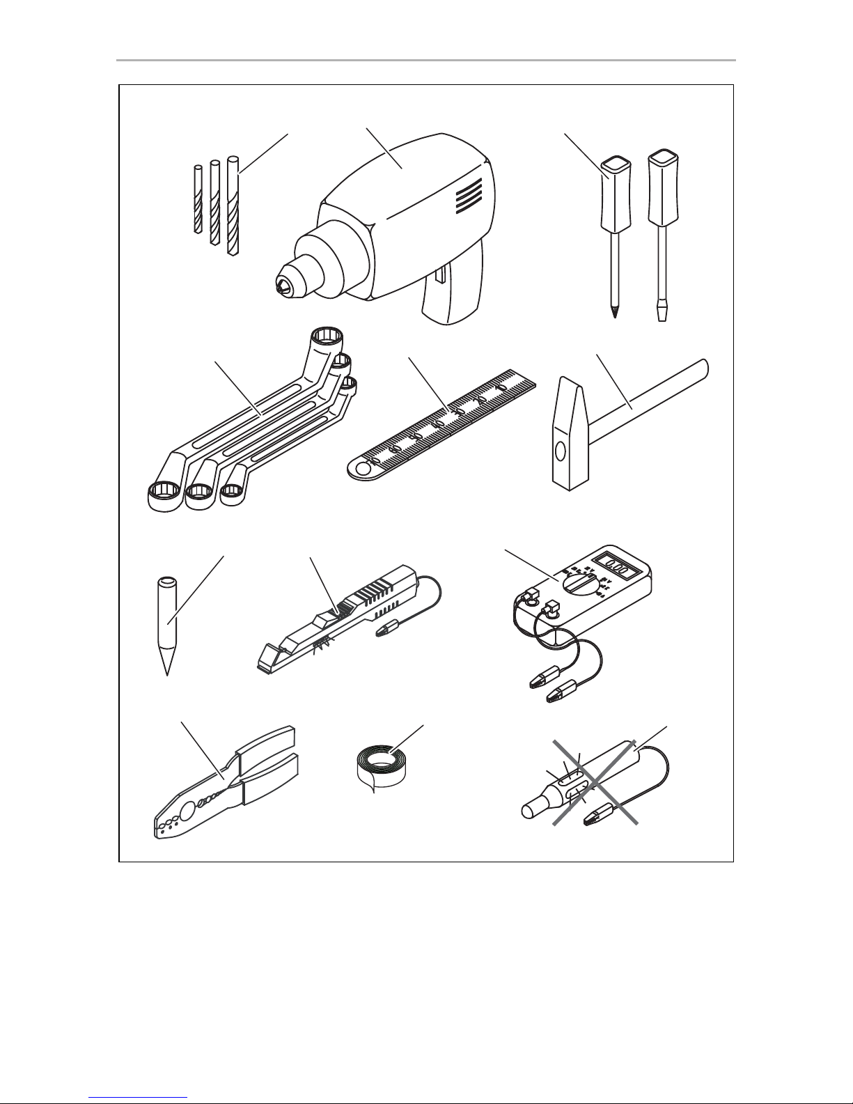
• Use a crimping tool (fig. 1 10, page 3) to connect the cables.
• Screw the cable for connections to cable 31 (earth)
– Screw on the cable using a cable terminal and serrated washer to one of the
vehicle's earth bolts or
– Screw the cable to the bodywork using a cable terminal and a self-tapping
screw
Make sure there is a good earth connection.
If you disconnect the negative terminal of the battery, the entire data stored in the
volatile memories will be lost.
• The following data must be reset, depending on the vehicle equipment options:
–Radio code
– Vehicle clock
–Timer
– On-board computer
– Seat position
You can find instructions for making these settings in the corresponding
operating manual.
Observe the following installation instructions:
• Secure the parts of the camera installed in the vehicle in such a way that they
cannot become loose under any circumstances (sudden braking, accidents) or
cause injuries to the occupants of the vehicle.
• Secure any parts of the system covered by the bodywork in such a manner that
they cannot be come loose or damage other parts and cables or impair vehicle
functions (steering, pedals, etc).
• To prevent damage when drilling, make sure there is sufficient space on the other
side for the drill head to come out (fig. 2, page 4).
• Deburr all drill holes and treat them with a rust-protection agent.

EN
Safety and installation instructions CAM44
14
• Always follow the safety instructions of the vehicle manufacturer.
Some work (e.g. on retention systems such as the AIRBAG etc.) may only be
performed by qualified specialists.
Observe the following instructions when working with electrical parts:
• When testing the voltage in electrical cables, only use a diode test lamp
(fig. 1 8, page 3) or a voltmeter (fig. 1 9, page 3).
Test lamps with an illuminant (fig. 1 12, page 3) consume voltages that are too
high and can damage the vehicle's electronic system.
• When making electrical connections, ensure that:
– They are not kinked or twisted
– They do not rub on edges
– They are not laid through sharp-edged ducts without protection (fig. 3,
page 4).
• Insulate all connections.
• Protect the cables from mechanical wear (for example rubbing against existing
cables) using cable binders or insulating tape.
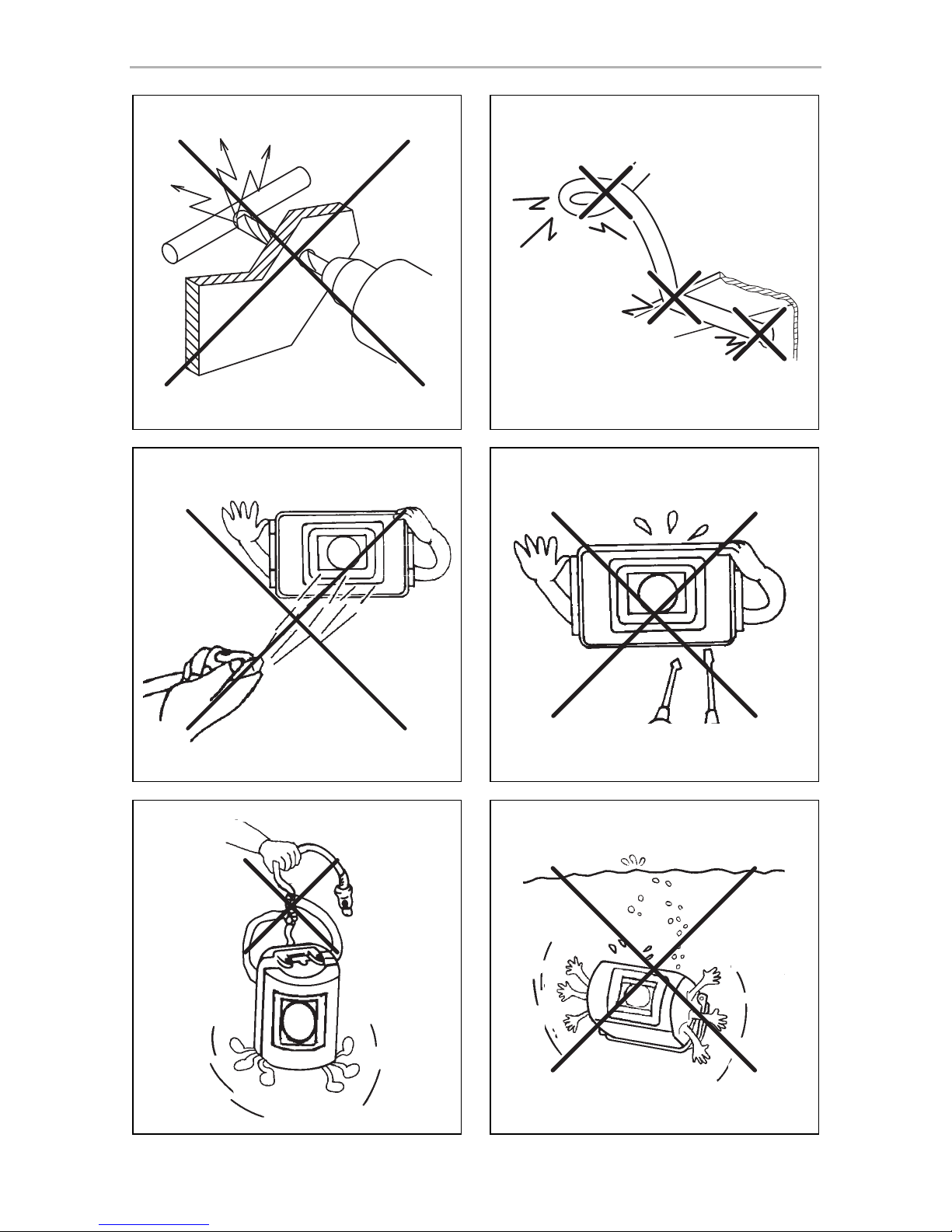
The camera is watertight. However, the seals on the camera cannot withstand a highpressure cleaner (fig. 4, page 4). Therefore, you should observe the following
instructions when handling the camera:
• Do not open the camera, as this impairs the watertightness and the function of
the camera (fig. 5, page 4).
• Do not pull on the cables, as this impairs the watertightness and the function of
the camera (fig. 6, page 4).
• The camera is not suitable for use under water (fig. 7, page 4)!

EN
CAM44 Scope of delivery
15
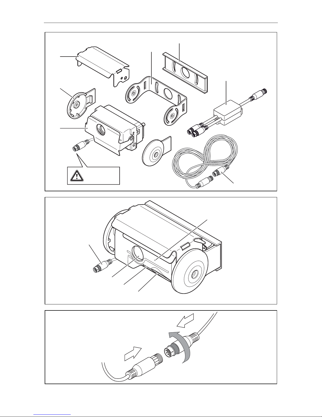
3Scope of delivery
4Accessories
Available as accessory (not included in scope of delivery):
5 Intended use
The CAM44 camera (item no. 9600000043) camera is designed primarily for use in
vehicles. It can be used in rear view video systems to observe the space behind the
vehicle from the driver's seat when manoeuvring or parking, for example.
!
No. in
fig. 8,
page 5
Quantity Description Ref. no.
11Camera with motorised protective
cover
22Cover
3 1 Camera guard
4 1 Camera bracket
5 1 Insulation pad
6 1 CAM44 adapter box 9102200078
7 1 Extension cables 9102200030
– 1 Fastening material
Description Ref. no.
AMP100 switch box 9600000210
WARNING!
Since rear view systems are designed merely as an additional aid for
reversing, they do not relieve you of the duty to take proper care
when reversing.

EN
Technical description CAM44
16
6 Technical description
The colour camera with integrated microphone is encased in an aluminium housing
and transmits image and sound to a monitor via a cable. It has a close-up lens and a
long-range lens. The infrared LEDs improve night vision.
The long-distance lens shows the space behind the vehicle as if you were looking
through a rear window. You can switch it on when you are not reversing.
The close-up lens (reversing camera) is a wide-angle lens, which shows the area
directly behind the vehicle. It is activated when you engage reverse gear.
The camera produces three distance marks in reversing mode which are shown on a
connected colour monitor as coloured lines.
The CAM44 camera is equipped with a motorised cover to protect against dirt.
I
The camera consists of the following elements:
NOTE
The cameras were equipped with a reverse display at the factory. Any
monitor that is connected therefore needs a normal picture function.
No. in
fig. 9, page 5
Description
1 6-pin connection cable
2 Long-range lens
3 Infrared LEDs
4 Close-up lens (reversing camera)
5 Microphone

EN
CAM44 Notes on the electrical connections
17
7 Notes on the electrical connections
7.1 Laying cables
A
Please therefore observe the following instructions:
• As far as possible, use original openings or alternative openings for the
connecting cable duct, e.g. the paneling edges, ventilation grilles or blank
panels. If no openings are available, you must drill holes for the cables. Check
beforehand that there is sufficient room for the drill head to come out on the other
side.
• Wherever possible, lay cables inside the vehicle, as they are better protected
there than outside.
If you do need to lay a cable outside the vehicle, ensure that it is well fastened
(use additional cable ties, insulating tape etc.).
• To prevent damage to the cables, when laying them, ensure that they are far
enough away from hot or moving vehicle components (exhaust pipes, drive
shafts, light systems, fans, heater etc.). Use corrugated piping or other protective
materials to protect against mechanical wear.
• Screw on the plug connections of the connecting cables to protect against water
penetration (fig. 0, page 5).
• When laying the cables, make sure:
– They are not kinked or twisted
– They do not rub on edges
– They are not laid through sharp-edged ducts without protection (fig. 3,
page 4).
• Attach the cables securely in the vehicles to prevent tripping hazards. Use cable
binders, insulating tape or glue the cables in place.
NOTICE! Risk of damage!
• To prevent damage, when drilling ensure that there is sufficient
space on the other side for the drill head to come out.
• Cables and connections which are not properly installed will cause
malfunctions or damage to components. Correct installation of
cables and connections is the basic prerequisite for lasting and
trouble-free operation of the retrofitted components.
• The cables may not be exposed for long periods to solvents such as
benzine, as the solvents can damage the cable.

EN
Notes on the electrical connections CAM44
18
• Protect every through-hole made in the bodywork against water penetration,
e.g. by using a cable with a sealant and by spraying the cable and the cable
sleeve with sealant.
I
7.2 Using branch connectors
To prevent loose connections in the branch connectors, it is important to ensure that
the cable cross sections fit into the branch connectors.
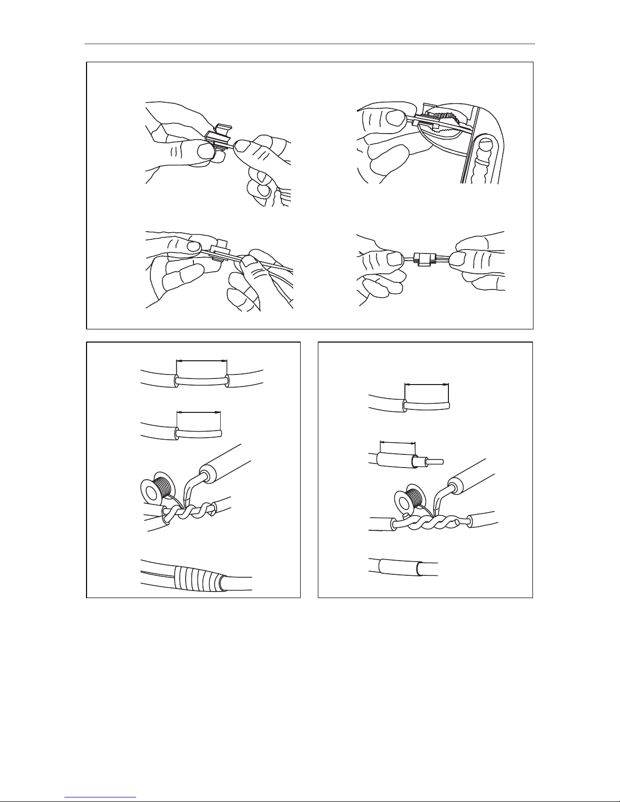
To use the branch connectors, proceed as follows:
➤ Insert the cable to be tapped in the front groove of the cable connector
(fig. a A, page 6).
➤ Insert the end of the new cable up to approx. 3/4 of the way into the rear groove
(fig. a B, page 6).
➤ Use a pair of combination pliers to close the connector by pressing the metal pin
in. This creates an electrical connection (fig. a C, page 6).
➤ Press down the safety cap until it snaps into place.
➤ Check that the connection is secure by gently tugging the cable (fig. a D,
page 6).
NOTE
Only start sealing through-holes when you have completed all
installation work on the camera and have laid the required cable lengths.

EN
CAM44 Notes on the electrical connections
19
7.3 Creating clean soldering joints
Proceed as follows to solder a cable to the original cables:
➤ Strip approx. 10 mm of insulation from the end of the original cable (fig. b A,
page 6).
➤ Strip approx. 15 mm of insulation from the end of the cable to be connected
(fig. b B, page 6).
➤ Wind the cable to be connected around the original cable and solder the two
cables together (fig. b C, page 6).
➤ Insulate the two cables with insulating tape (fig. b D, page 6).
Proceed as follows to solder two cables together:
➤ Strip the two cables (fig. c A, page 6).
➤ Place a shrink sleeve with a length of approx. 20 mm over the cable (fig. c B,
page 6).
➤ Twist the cables together and solder them (fig. c C, page 6).
➤ Place a shrink sleeve over the soldered point and heat it briefly (fig. c D,
page 6).

EN
Fitting the camera CAM44
20
8 Fitting the camera
8.1 Tools required
For installation and assembly you will need the following tools:
• Drill bit set (fig. 1 1, page 3)
• Drill (fig. 1 2, page 3)
• Screwdriver (fig. 1 3, page 3)
• Set of ring or open-ended spanners (see fig. 1 4, page 3)
• Measuring ruler (fig. 1 5, page 3)
• Hammer (fig. 1 6, page 3)
• Centre punch (fig. 1 7, page 3)
To establish and test the electrical connection, the following tools are required:
• Diode test lamp (fig. 1 8, page 3) or voltmeter (fig. 1 9, page 3)
• Insulating tape (fig. 1 11, page 3)
• Cable bushing sleeves (optional)
To fasten the cables you may require additional cable binders.
8.2 Fitting the camera
!
I
CAUTION!
Select a location for the camera and attach it firmly enough so that it
cannot under any circumstances fall off and injure bystanders (e.g. by
being knocked off by branches brushing over the roof of the vehicle).
NOTE
If installing the camera alters the vehicle height or the length specified in
the vehicle documents, your vehicle must be inspected by the
appropriate authorities.
Make sure that you are in possession of vehicle documents verifying that
your vehicle has passed this inspection.

EN
CAM44 Fitting the camera
21
Observe the following installation instructions:
• Fix the camera at a height of at least two metres for an adequate view.
Make sure that you have a firm place from which to work when installing the
camera.
• Make sure that the installation location of the camera is sufficiently firm (e. g. to
prevent the camera from being knocked down by branches that may brush the
roof of the vehicle).
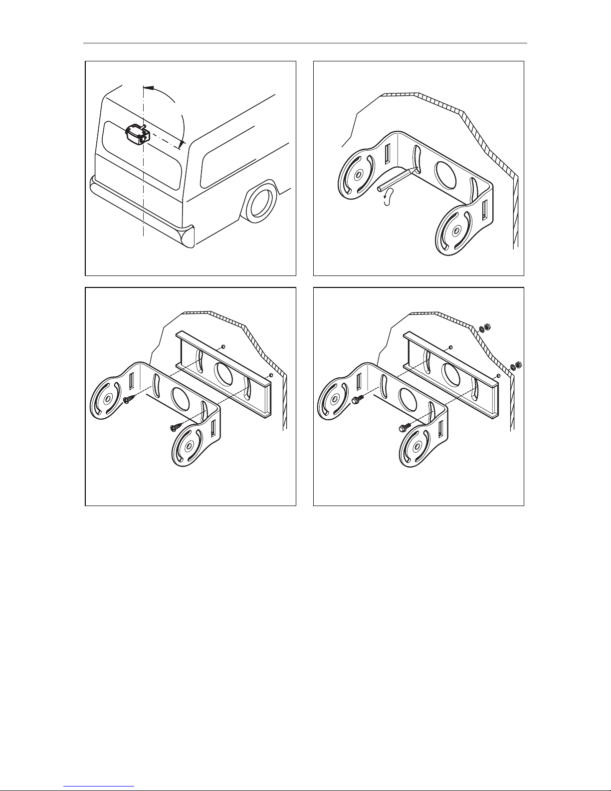
• Mount the camera horizontally and in the middle of the rear of the vehicle
(fig. d, page 7).
• Always use the supplied insulation pad (fig. 8 5, page 5). This prevents residual
current caused by a poor earth connections in the vehicle. Residual current can
cause lines of interference in the picture or buzzing in the loudspeakers or even
damage components.
• The most secure type of attachment is with screws fitted through the body.
Please observe the following instructions:
– There must be sufficient space behind the chosen installation location to be
able to carry out the mounting procedure.
– Suitable measures must be taken to prevent water penetrating through any
holes made (e.g. by using screws and sealant and/or spraying the outer
attachment parts with a sealant).
– The location on the body where you wish to attach the camera must be rigid
enough to allow the camera to be tightly fastened.
• Check beforehand that there is sufficient space on the other side for the drill head
to come out (fig. 2, page 4).
• If you are not sure about the location you have chosen, ask your vehicle manufacturer or dealer.
I
To perform the installation, proceed as follows:
➤ Hold the camera holder at the chosen location and mark at least two different
points for the drill holes (fig. e, page 7).
➤ Using a hammer and centre punch, gently pre-punch the previously marked
points to prevent the drill head from slipping off.
NOTE
We recommend greasing the threads of the screws to prevent
corrosion.

EN
Fitting the camera CAM44
22
If you want to screw on the camera with self-tapping screws (fig. f,
page 7)
A
➤ Drill 4 mm diameter holes at the points you just marked.
➤ Deburr all drill holes and apply rust-protection.
➤ Stick the double-sided adhesive insulation (fig. 8 5, page 5) to the assembly
side of the bracket.
The insulation plate serves as a seal and protects the paint.
➤ Screw the camera bracket on with the 5 x 20 mm self-tapping screws.
If you would like to attach the camera with threaded screws fitted through
the construction (fig. g, page 7)
A
➤ Drill 5.5 mm diameter holes at the points you just marked.
➤ Deburr all drill holes and apply rust-protection.
➤ Stick the double-sided adhesive insulation (fig. 8 5, page 5) to the assembly
side of the bracket.
The insulation plate serves as a seal and protects the paint.
➤ Screw the camera holder on with the M5 x 20 mm threaded screws.
Depending on the thickness of the construction, you may require longer
threaded screws.
NOTICE!
Self-tapping screws may only be fastened to steel metal with a minimum
thickness of 1.5 mm.
NOTICE!
When tightening the nuts, make sure that they cannot be pulled through
the construction.
You may have to use bigger washers or plates.

EN
CAM44 Fitting the camera
23
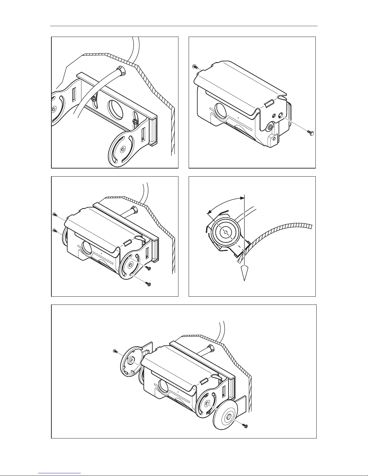
Creating a through-hole for the camera connection cable (fig. h, page 8)
I
A
➤ Drill a hole of Ø 16 mm near the camera.
➤ Deburr all drill holes that have been made in the sheet metal and apply
rust-protection.
➤ Place cable sleeves in all sharp-edged ducts.
Attaching the camera and camera guard
A
➤ Push the camera guard (fig. 8 3, page 5) over the camera in such a way that:
– The fixing hole of the camera guard (fig. i, page 8) is over the 3 mm thread
of the camera.
– The two other fixing holes (fig. i, page 8) are over the 3 mm threads of the
camera.
➤ Secure the camera guard with the two M3 x 6 mm screws in the hole (fig. i,
page 8).
➤ Push the camera into the bracket (fig. j, page 8).
A
➤ Secure the camera loosely with the four M3 x 8 mm screws in the two other
fixing holes (fig. j, page 8).
The camera is now centred.
NOTE
If possible, use available openings – such as ventilation grilles – to feed
the connection cables through. If there are no existing openings, you
must drill a hole with a 16 mm diameter.
NOTICE! Risk of damage!
Ensure that there is sufficient space on the other side for the drill head to
come out
NOTICE!
Never mount the camera without the additional camera guard.
To mount the camera guard, only use the M3 x 6 mm screws provided.
Longer screws will damage the camera.
NOTICE!
Only use the screws supplied to mount the camera in the camera holder.
Longer screws will damage the camera.

EN
Fitting the camera CAM44
24
➤ Align the camera so that the lens is at an angle of approx. 20° to the vertical axis
of the vehicle (fig. k, page 8).
I
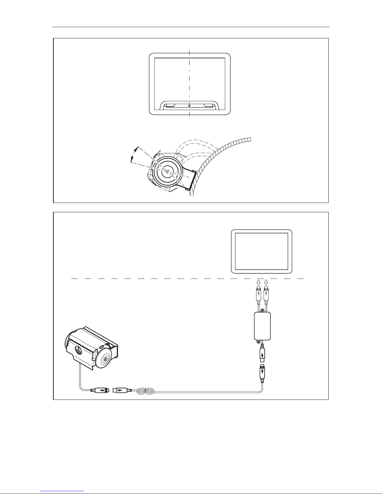
8.3 Connecting the camera
I
➤ Guide the camera cable into the vehicle interior.
➤ Insert the plug of the camera cable into the socket of the extension cable.
➤ Screw on the plug connections of the connecting cables to protect against water
penetration (fig. 0, page 5).
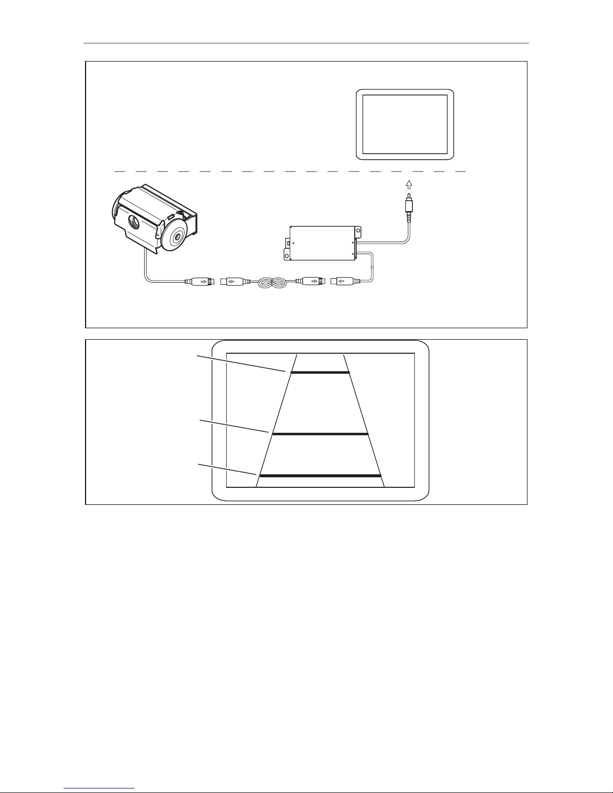
8.4 Connecting the 9102200078 switchbox
(fig. n, page 9)
The switchbox is supplied ready for installation.
➤ Fasten the switchbox at a suitable point.
➤ Connect the control box electrically as follows:
– Connect the camera inputs on the monitor to the “V1” and “V2” connections.
– Connect the system cable from the camera to the “TWIN” connection.
The camera is switched on and off in reverse gear or using the camera selection
button on the monitor.
NOTE
Do not tighten the four M3 x 8 mm screws until you have aligned the
camera (see chapter “Checking the function and setting the camera” on
page 25).
To do this you must first install and connect a monitor.
NOTE
• Lay the camera cable so that should you need to remove the camera,
you can access the plug connection between the camera and the
extension cable easily. This considerably eases dismantling work.
• To minimise corrosion in the plug, apply a small amount of grease –
such as pin grease – inside the plug.

EN
CAM44 Fitting the camera
25
8.5 Connecting the AMP100 switchbox
(fig. o, page 10)
I
The switch box (not included in delivery) is ready for installation.
➤ Mount the switchbox as described in the corresponding installation and
operating manual.
I
➤ Connect the switchbox electrically as described in the corresponding installation
and operating manual.
8.6 Checking the function and setting the camera
I
➤ Check the function of the camera after you have connected it to a monitor.
➤ Align the camera using the image on the monitor to help you:
The monitor image should show the rear or the bumper of the vehicle at the
bottom edge of the screen. The middle of the bumper should be in the middle
of the screen (fig. m, page 9).
➤ Tighten the four fastening screws of the camera.
➤ Place the side covers on and secure each one with a fastening screw (fig. l,
page 8).
Settings for contrast and brightness can be made on the monitor.
NOTE
If you would like to use both camera modules when driving forwards,
you will need to fit the flip switch supplied (see the installation and
operating manual for AMP100).
NOTE
Output “2” on the switchbox is an auxiliary output, e.g. for connecting
an external monitor.
NOTE
The distance values of the distance markers (see chapter “Estimating distances” on page 26) only apply when the camera is installed at a height
of approx. 230 – 250 cm.
Check the actual installation height once you have installed the camera.
If the installation height deviates from these values, determine the actual
distance values for the distance markers.

EN
Using the camera CAM44
26
9 Using the camera
9.1 Estimating distances
The camera produces three distance marks in reversing mode which are shown on a
connected colour monitor as coloured lines (fig. p, page 10).
The lines make it easier to estimate the distance of the vehicle to an obstacle.
When the camera is installed at a height of approx. 230 – 250 cm, the lines show the
following distances:
10 Cleaning and caring for the camera
A
➤ Clean the camera with a soft, damp cloth from time to time.
11 Guarantee
The statutory warranty period applies. If the product is defective, please contact the
manufacturer's branch in your country (see the back of the instruction manual for the
addresses) or your retailer.
For repair and guarantee processing, please send the following items:
• Defect components
• A copy of the receipt with purchasing date
• A reason for the claim or description of the fault
Colour Distance
Green (A) approx. 3 m
Yellow (B) approx. 1 m
Red (C) approx. 0.3 m
NOTICE!
Do not use any sharp or hard objects for cleaning since they may
damage the device.

EN
CAM44 Disposal
27
12 Disposal
➤ Place the packaging material in the appropriate recycling waste bins wherever
possible.
M
If you wish to finally dispose of the product, ask your local recycling centre
or specialist dealer for details about how to do this in accordance with the
applicable disposal regulations.
13 Technical data
PerfectView CAM44
Ref. no.: 9600000043
Image sensor: Long-range: 1/4" Color CMOS Sensor
approx. 290000 pixels, 648(H) x 488(V)
Close-up: 1/3" CMOS,
762(H) x 504(V)
TV system: PAL
Sensitivity: < 1 lux or 0.0 lux with IR LED (close-up)
Viewing angle: Long-distance lens: approx. 50°
Close-up lens: approx. 140° diagonal
Microphone sensitivity: Approx. 56 dB
Storage temperature: –30 °C to +85 °C
Operating temperature: –30 °C to +70 °C
Operating voltage: 12 – 16 Vg
Consumption: max. 4 W
Dimensions W x H x D (with holder): 114 x 74 x 62 mm
Weight: Approx. 360 g
Certification
E4

DE
CAM44
28
Bitte lesen Sie diese Anleitung vor Einbau und Inbetriebnahme sorgfältig
durch und bewahren Sie sie auf. Geben Sie sie im Falle einer Weitergabe
des Produktes an den Nutzer weiter.
Inhaltsverzeichnis
1 Erklärung der Symbole . . . . . . . . . . . . . . . . . . . . . . . . . . . . . . . . . . . . . . . . . 29
2 Sicherheits- und Einbauhinweise . . . . . . . . . . . . . . . . . . . . . . . . . . . . . . . . . 29
3 Lieferumfang . . . . . . . . . . . . . . . . . . . . . . . . . . . . . . . . . . . . . . . . . . . . . . . . . 32
4 Zubehör. . . . . . . . . . . . . . . . . . . . . . . . . . . . . . . . . . . . . . . . . . . . . . . . . . . . . 32
5 Bestimmungsgemäßer Gebrauch . . . . . . . . . . . . . . . . . . . . . . . . . . . . . . . . 32
6 Technische Beschreibung . . . . . . . . . . . . . . . . . . . . . . . . . . . . . . . . . . . . . . 33
7 Hinweise zum elektrischen Anschluss . . . . . . . . . . . . . . . . . . . . . . . . . . . . . 34
8 Kamera montieren. . . . . . . . . . . . . . . . . . . . . . . . . . . . . . . . . . . . . . . . . . . . . 36
9 Kamera verwenden. . . . . . . . . . . . . . . . . . . . . . . . . . . . . . . . . . . . . . . . . . . . 43
10 Kamera pflegen und reinigen . . . . . . . . . . . . . . . . . . . . . . . . . . . . . . . . . . . . 43
11 Gewährleistung. . . . . . . . . . . . . . . . . . . . . . . . . . . . . . . . . . . . . . . . . . . . . . . 43
12 Entsorgung . . . . . . . . . . . . . . . . . . . . . . . . . . . . . . . . . . . . . . . . . . . . . . . . . . 44
13 Technische Daten . . . . . . . . . . . . . . . . . . . . . . . . . . . . . . . . . . . . . . . . . . . . . 44

DE
CAM44 Erklärung der Symbole
29
1 Erklärung der Symbole
!
!
A
I
2 Sicherheits- und Einbauhinweise
Beachten Sie die vom Fahrzeughersteller und vom Kfz-Handwerk vorgeschriebenen Sicherheitshinweise und Auflagen!
Der Hersteller übernimmt in folgenden Fällen keine Haftung für Schäden:
• Montage- oder Anschlussfehler
• Beschädigungen am Produkt durch mechanische Einflüsse und Über-
spannungen
• Veränderungen am Produkt ohne ausdrückliche Genehmigung vom Hersteller
• Verwendung für andere als die in der Anleitung beschriebenen Zwecke
Beachten Sie deshalb folgende Hinweise:
• Klemmen Sie wegen der Kurzschlussgefahr vor Arbeiten an der Fahrzeugelektrik
immer den Minuspol ab.
Bei Fahrzeugen mit Zusatzbatterie müssen Sie an dieser ebenfalls den Minuspol
abklemmen.
WARNUNG!
Sicherheitshinweis: Nichtbeachtung kann zu Tod oder schwerer
Verletzung führen.
VORSICHT!
Sicherheitshinweis: Nichtbeachtung kann zu Verletzungen führen.
ACHTUNG!
Nichtbeachtung kann zu Materialschäden führen und die Funktion des
Produktes beeinträchtigen.
HINWEIS
Ergänzende Informationen zur Bedienung des Produktes.

DE
Sicherheits- und Einbauhinweise CAM44
30
• Unzureichende Leitungsverbindungen können zur Folge haben, dass durch
Kurzschluss
– Kabelbrände entstehen,
– der Airbag ausgelöst wird,
– elektronische Steuerungseinrichtungen beschädigt werden,
– elektrische Funktionen ausfallen (Blinker, Bremslicht, Hupe, Zündung, Licht).
• Verwenden Sie bei Arbeiten an den folgenden Leitungen nur isolierte
Kabelschuhe, Stecker und Flachsteckhülsen:
– 30 (Eingang von Batterie Plus direkt),
– 15 (Geschaltetes Plus, hinter Batterie),
– 31 (Rückleitung ab Batterie, Masse),
– 58 (Rückfahrscheinwerfer).
Verwenden Sie keine Lüsterklemmen.
• Verwenden Sie eine Krimpzange (Abb. 1 10, Seite 3) zum Verbinden der
Kabel.
• Schrauben Sie das Kabel bei Anschlüssen an Leitung 31 (Masse)
– mit Kabelschuh und Zahnscheibe an eine fahrzeugeigene Masseschraube
oder
– mit Kabelschuh und Blechschraube an das Karosserieblech.
Achten Sie auf eine gute Masseübertragung!
Beim Abklemmen des Minuspols der Batterie verlieren alle flüchtigen Speicher der
Komfortelektronik ihre gespeicherten Daten.
• Folgende Daten müssen Sie je nach Fahrzeugausstattung neu einstellen:
–Radiocode
–Fahrzeuguhr
– Zeitschaltuhr
– Bordcomputer
– Sitzposition
Hinweise zur Einstellung finden Sie in der jeweiligen Bedienungsanleitung.
Beachten Sie folgende Hinweise bei der Montage:
• Befestigen Sie die im Fahrzeug montierten Teile der Kamera so, dass sie sich
unter keinen Umständen (scharfes Abbremsen, Verkehrsunfall) lösen und zu
Verletzungen der Fahrzeuginsassen führen können.
• Befestigen Sie verdeckt unter Verkleidungen anzubringende Teile des Systems
so, dass sie sich nicht lösen oder andere Teile und Leitungen beschädigen und
keine Fahrzeugfunktionen (Lenkung, Pedale usw.) beeinträchtigen können.
 Loading...