

Page 1
POWER AND CONTROLS
CONTROL
EN
FR
Dometic Interact
Operation Manual . . . . . . . . . . . . . . . . . . . 2
Dometic Interact
Manuel d’utilisation . . . . . . . . . . . . . . . . . 32
Form No. 3317348.000 10/2019 | ©2019 Dometic Corporation
Page 2

Contents Dometic Interact
Service Center & Dealer Locations
Visit: www.dometic.com
Read these instructions carefully. These instructions MUST stay with this product.
Contents
1 Explanation of Symbols and
Safety Instructions . . . . . . . . . . . . . . . . . . . . . . . .3
1.1 Recognize Safety Information . . . . . . . . . . . . . . .3
1.2 Understand Signal Words . . . . . . . . . . . . . . . . . .3
1.3 Supplemental Directives . . . . . . . . . . . . . . . . . . .3
1.4 General Safety Messages . . . . . . . . . . . . . . . . . .3
2 General Information. . . . . . . . . . . . . . . . . . . . . . .3
2.1 Key Features . . . . . . . . . . . . . . . . . . . . . . . . . . . . .4
3 Intended Use. . . . . . . . . . . . . . . . . . . . . . . . . . . . .4
4 Operation . . . . . . . . . . . . . . . . . . . . . . . . . . . . . . .4
4.1 Touch-Screen Navigation and Use . . . . . . . . . . .5
4.1.1 Main Navigation Screen and Icons. . . . .5
4.1.2 Climate Screens. . . . . . . . . . . . . . . . . . . .6
4.1.3 Mechanical Screen . . . . . . . . . . . . . . . . .7
4.1.4 Lights Screen . . . . . . . . . . . . . . . . . . . . . .8
4.1.5 Power Screen . . . . . . . . . . . . . . . . . . . . .8
4.1.15 Clock Screen . . . . . . . . . . . . . . . . . . . . 25
4.1.16 Notifications Screen . . . . . . . . . . . . . . 26
4.2 Mobile Application Navigation and Use. . . . . 27
4.2.1 Prerequisites . . . . . . . . . . . . . . . . . . . . 27
4.2.2 Initial Connection. . . . . . . . . . . . . . . . . 27
4.2.3 Password Settings . . . . . . . . . . . . . . . . 27
4.2.4 Navigation and Use . . . . . . . . . . . . . . . 28
5 Maintenance . . . . . . . . . . . . . . . . . . . . . . . . . . . 30
5.1 Care and Cleaning . . . . . . . . . . . . . . . . . . . . . . 30
5.2 Preventive Maintenance. . . . . . . . . . . . . . . . . . 30
6 Troubleshooting. . . . . . . . . . . . . . . . . . . . . . . . 30
7 Disposal. . . . . . . . . . . . . . . . . . . . . . . . . . . . . . . . 31
LIMITED ONE-YEAR WARRANTY. . . . . . . . . . . . . . 31
4.1.6 AGS Screen . . . . . . . . . . . . . . . . . . . . . . 11
4.1.7 Tanks Screen . . . . . . . . . . . . . . . . . . . . .13
4.1.8 Alarms Screen . . . . . . . . . . . . . . . . . . . .13
4.1.9 Settings Screen . . . . . . . . . . . . . . . . . . .16
4.1.10 Programs Screen . . . . . . . . . . . . . . . . . .21
4.1.11 Fuses Screen . . . . . . . . . . . . . . . . . . . . 23
4.1.12 Bedroom Screen . . . . . . . . . . . . . . . . . 24
4.1.13 Bathroom Screen . . . . . . . . . . . . . . . . 24
4.1.14 Entry Screen. . . . . . . . . . . . . . . . . . . . . 25
2
EN
Page 3

Dometic Interact Explanation of Symbols and Safety Instructions
1 Explanation of Symbols and Safety Instructions
This manual has safety information and instructions to
help you eliminate or reduce the risk of accidents and
injuries.
1.1 Recognize Safety Information
D
This is the safety alert symbol.
It is used to alert you to potential physical injury
hazards. Obey all safety messages that follow this
symbol to avoid possible injury or death.
1.2 Understand Signal Words
A safety symbol and/or signal word identify safety
messages and indicate the hazard severity.
D
DANGER!
Indicates a hazardous situation that, if not avoided,
will result in death or serious injury.
• The installation must comply with all applicable local or
national codes, including the latest edition of the
following standards:
U.S.A.
– ANSI/NFPA70, National Electrical Code (NEC)
– ANSI/NFPA 1192, Recreational Vehicles Code
– ANSI Z21.57, Recreational Vehicles Code
Canada
– CSA C22.1, Parts l & ll, Canadian Electrical Code
– CSA Z240 RV Series, Recreational Vehicles
1.4 General Safety Messages
!
WARNING: FIRE, IMPACT, AND/OR
EXPLOSION HAZARD
Failure to obey the following warnings could result in
death or serious injury:
• Use only Dometic replacement parts and components
that are specifically approved for use with the
appliance.
!
WARNING:
Indicates a hazardous situation that, if not avoided,
could result in death or serious injury.
CAUTION:
!
Indicates a hazardous situation that, if not avoided,
could result in minor or moderate injury.
NOTICE: Used to address practices not related to
physical injury.
Indicates additional information that is not related to
I
physical injury.
1.3 Supplemental Directives
To reduce the risk of accidents and injuries, please
observe the following directives before proceeding to
operate this appliance:
• Read and follow all safety information and instructions.
• Read and understand these instructions before
operating this product.
• Use care when diagnosing and/or adjusting
components on a powered unit.
• Do not modify this product in any way. Modifications
can be extremely hazardous.
• Do not allow children to play with this product or with
fixed controls (if applicable).
2 General Information
Dometic Interact provides a central control and
monitoring hub for the appliances in your recreational
vehicle (RV). All of the LCDs in the RV communicate with
each other continuously over the RV-C bus. When one
LCD is down, the others can continue to operate.
Dometic Interact does not replace the actual hardware
controllers for the systems within the coach; it is a display
that sends the signals and commands to various
components (such as load boxes) regarding the actions
that should be taken.
EN
3
Page 4

Intended Use Dometic Interact
The Dometic Interact system allows you to:
• Control the climate, lighting, awnings, slide-outs,
water systems, door locks, and generators from
convenient locations in and around your vehicle.
• Monitor the status of water tank levels, LP gas levels,
and battery levels from any location.
• Predict the usage of onboard components. Predictive
usage technology provides on-screen reporting of vital
water and power resources, and determines when you
should consider refilling or recharging.
2.1 Key Features
Dometic Interact has the following features and benefits
when integrated with your RV:
• Convenient 3.5 in. (89 mm) touch-screen display
• Wireless network control and mobile application
• Single- or multiple-screen interfaces
• One-touch control for user-programmable modes,
such as Home, Away, and Sleep
• Haptic touch and sound feedback
3 Intended Use
Dometic Interact is intended to be used in conjunction
with the existing control and/or monitoring devices
within your RV. It creates a central hub that you can use to
efficiently control and monitor your appliances, via the
onboard touch-screen display or from your mobile
application.
The manufacturer accepts no liability for damage in the
following cases:
• Faulty assembly or connection
• Damage to the product resulting from mechanical
influences and excess voltage
• Alterations to the product without express permission
from the manufacturer
• Use for purposes other than those described in the
operating manual
Dometic Corporation reserves the right to modify
appearances and specifications without notice.
4 Operation
• On-screen predictive usage
• Control and monitoring of your RV's vital and
convenience features, such as:
– Lights
– Climate
– Generator
– Inverter
– Water holding tanks
– Water pump
– Awning
– Alarm clock
– Coach battery
!
WARNING: FIRE AND/OR IMPACT HAZARD.
Failure to obey the following warnings could result in
death or serious injury:
• Avoid improper operation of the unit. Refer to the
operating manuals for the specific products that this
unit controls to understand and obey the applicable
safety precautions.
• Do not allow anyone (including children) with reduced
physical, sensory, or mental capabilities, or lack of
experience and knowledge to use this product, unless
they have been given supervision or instruction
concerning the use of this product by a person
responsible for their safety.
NOTICE: You can use multiple screens for different
operations at the same time, but avoid performing a
single operation from multiple screens.
Dometic Interact can be operated from the onboard
touch-screen display, or via the mobile application
(available for download on most mobile devices).
4
EN
Page 5
Dometic Interact Operation
Refer to the following sections for more information about
touch-screen and mobile application navigation and use,
including information about:
• UI screens and buttons
• Control and monitoring functionality
• Prerequisites (mobile only)
4.1 Touch-Screen Navigation and Use
This section describes how to use Dometic Interact from
the touch-screen display.
Refer to Mobile Application Navigation and Use to learn
how to operate the control using the mobile application.
The screens presented in this section vary according
I
to the available appliances and the layout of your RV.
4.1.1 Main Navigation Screen and Icons
The Main Navigation screen is the default landing screen
that you will use to navigate through the various areas of
the control.
• Power
• AGS
• Tanks
• Alarms
• Settings
• Programs
• Fuses
• Rooms
• Notifications
The following table describes the buttons that are used
for general navigation of the various screens and to select
settings.
Button Description
Tap this icon to change the layout of the Main Navigation screen to list view.
Tap this icon to change the layout of the Main Navigation screen to grid view.
Tap this icon to close the current screen and return
to the previous screen.
Tap this icon to reach the Programs screen.
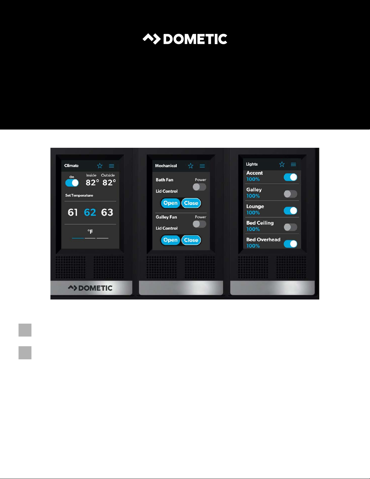
1 Main Navigation Screen
The Main Navigation screen provides access to the
following screens:
• Climate
• Mechanical
• Lights
Tap this icon to reach the Notifications screen.
Tap this icon to return to the Main Navigation
screen.
Use toggle buttons to enable or disable functions.
Use tumblers to select from a list of available
options. Tumblers can be horizontal or vertical.
Scroll to bring the desired setting to the middle
position.
Use sliders to increase or decrease the intensity of
certain settings, such as light sources. Sliders can
be horizontal or vertical. Slide the dot along the
bar to the desired intensity. The indicator shows
the intensity level as a percentage.
EN
5
Page 6
Operation Dometic Interact
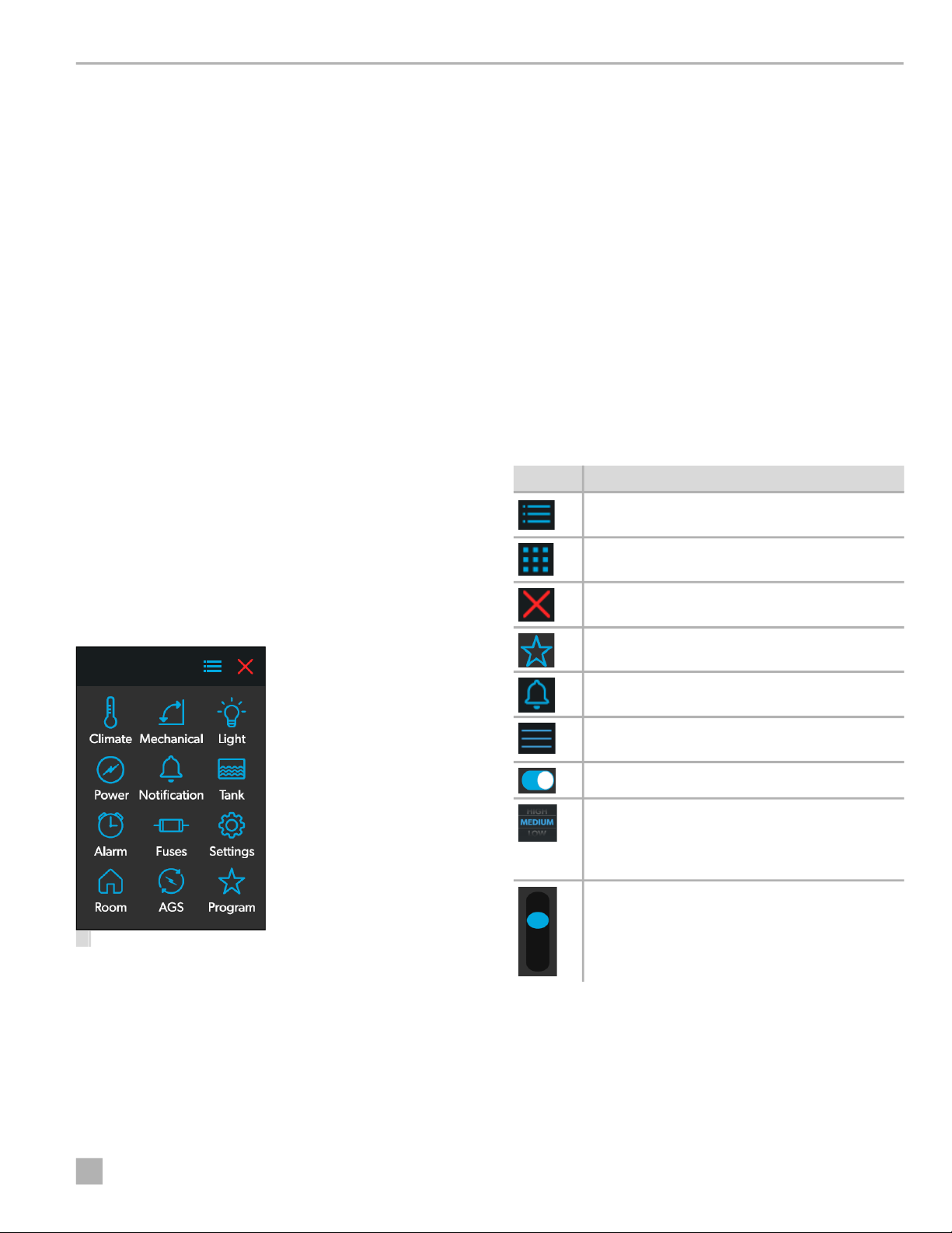
4.1.2 Climate Screens
The Climate screens allow you to control and monitor the
climate within your RV, such as cooling, heating, and
vents.
From these screens, you can control or monitor the
following functions:
• Current Temperatures: These indicate the current
indoor and outdoor air temperatures.
I
• Power: The default state for this button is off. Tap the
• Set Temperature: This area displays a set of numbers
• Climate Mode: Tap the center bar of the lower
The outdoor temperature sensor may not be
available on all models.
toggle button once to turn climate control on. The
applicable climate control appliance will be activated,
depending on the set temperature and the
temperature type currently selected.
ranging from 40–90 °F (4–32 °C), in ascending order.
Use the tumbler to select your desired temperature
setting.
section indicator to view the climate mode settings.
There are four climate mode options: Auto, Fan Only,
Heat, and Cool.
Use the tumbler to select your desired mode:
– Choose Auto to allow the system to select the
appropriate operating mode based on the
configured settings and actual temperature
readings.
– Choose Fan Only to turn off the AC or furnace and
use only the fan for the AC unit.
– Choose Heat to turn on the furnace or heat pump.
– Choose Cool to turn on the AC unit.
I
• Fan Level: Tap the right bar of the lower section
Refer to the Settings Screen section for
information about the Secondary Heat
Management System settings.
When Cool or Auto modes are chosen, a spinning
icon will appear to indicate that the AC unit is
initializing. This can take up to three minutes.
indicator to view the fan speed settings for the AC unit.
There are four fan speed options: low, medium, high,
and auto.
2 Climate Screens
6
Use the tumbler to select your desired fan speed:
– Choose L, M, or H to set the fan to the low, medium,
or high setting.
EN
Page 7
Dometic Interact Operation
– Choose A to set the fan to the Auto setting, where
the unit will determine the appropriate fan speed
automatically based on the set temperature and the
actual temperature readings.
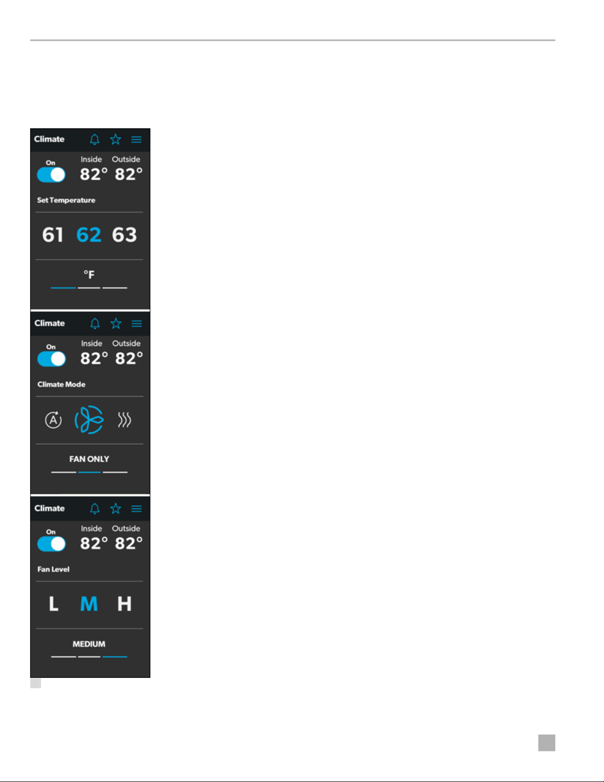
4.1.3 Mechanical Screen
The Mechanical screen allows you to control and monitor
your mechanical appliances, such as awnings and
ventilation fans.
• Vent Fan Speed: The Fan Speed buttons control the
speed of the galley vent fans. Tap a button to choose
the desired vent fan speed from the four available
options, which represent the percentages of the
maximum fan speed: 0, 33, 66, or 100.
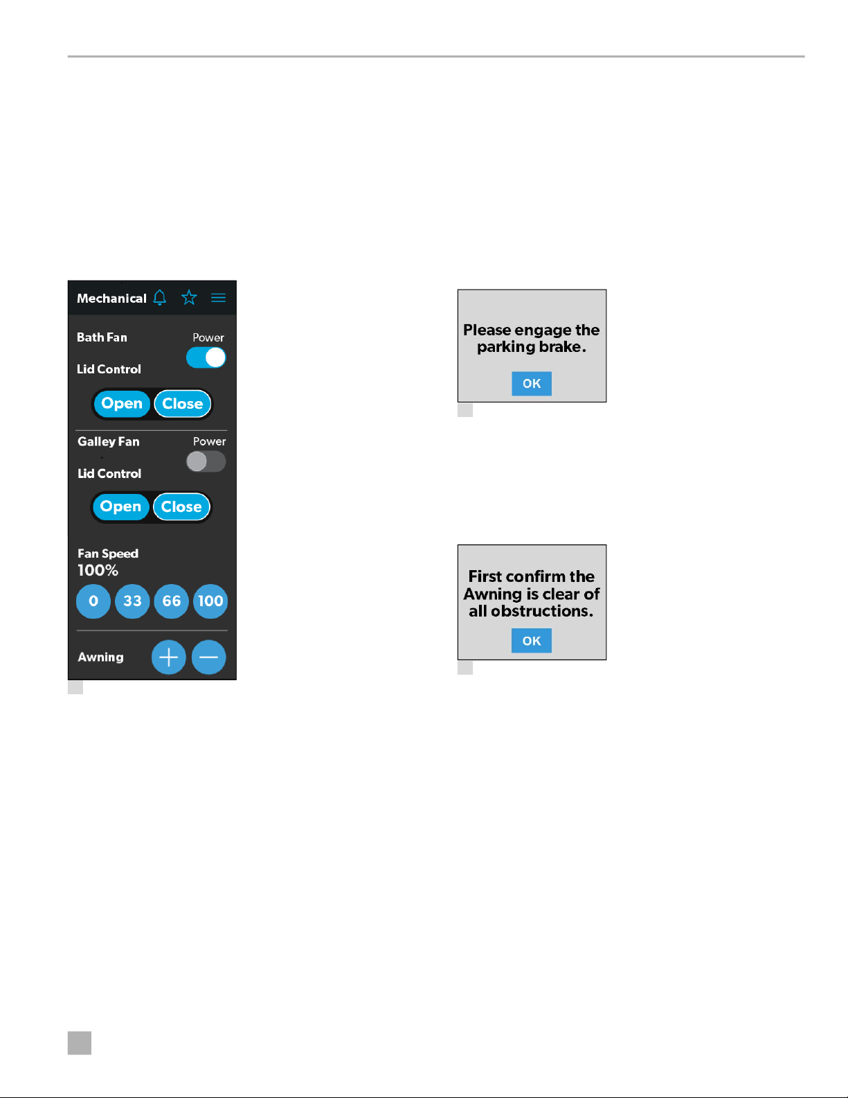
• Awnings: The Awning buttons allow you to extend or
retract the awning. Awnings will have no control unless
the parking brake is engaged. If you attempt to extend
or retract the awnings while the parking brake is not
engaged, an alert appears.
4 Parking Brake Alert
The Awning buttons function as follows:
– Tap the plus button (+) to extend the awning or the
minus button (–) to retract the awning, and a pop-up
message appears (assuming the parking brake is
engaged).
3 Mechanical Screen
From this screen, you can control and monitor the
following functions:
• Power: The default state for the bath and galley fan
Power buttons is off. Tap the Power button once to turn
the fan on.
I
The lid must be open before the fan motor turns
on. If the lid is closed when you attempt to turn the
fan motor on, the lid will open automatically.
• Lid Control: The bath and galley fan lids are closed by
default. Tap the Open or Close button for the galley or
bath fan lid control to open or close the lids. A white
outline around the button indicates the status of the lid.
EN
5 Awning Clear Message
– After you have verified that the awning is clear of
obstructions, tap the OK button. The awning is now
ready to extend or retract.
7
Page 8
Operation Dometic Interact
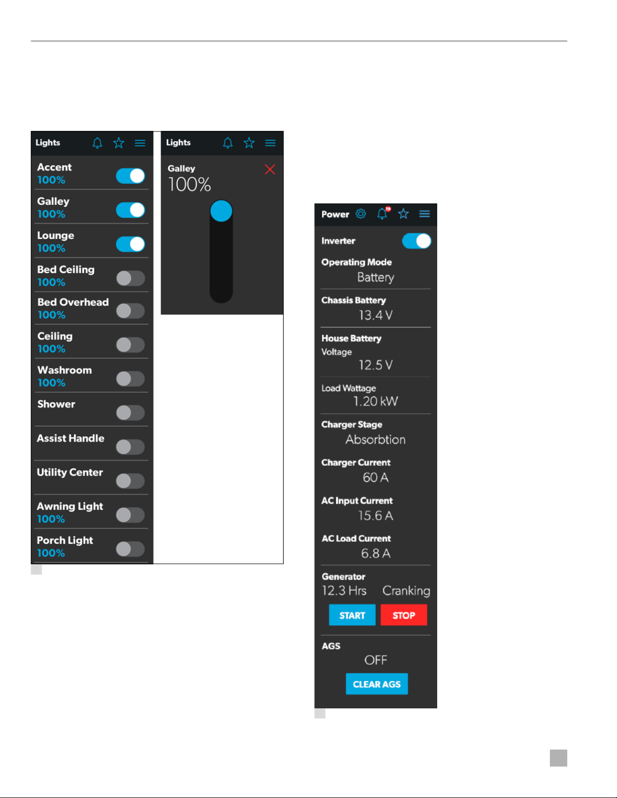
4.1.4 Lights Screen
The Lights screen allows you to control and monitor the
various lighting sources throughout your RV, such as
accent, galley, and utility lighting.
• Dimmer/Slider: The light source intensity is
indicated when the power to the light is activated. Tap
the intensity indicator to open the vertical slider screen,
where you can adjust the light source intensity.
4.1.5 Power Screen
The Power screen allows you to monitor and control the
available power sources for your RV, such as the battery,
inverter, and generator.
6 Lights Screen
These images show an example layout. Your Lights
I
screen will vary according to the available lights and
your RV layout.
From these screens, you can control and monitor the
following functions:
• Power Buttons: The power buttons are used to turn a
particular light or set of lights on and off. Tap the toggle
or on/off buttons as desired to turn the lights on or off.
8
7 Power Screen
EN
Page 9
Dometic Interact Operation
From the Power screen, you can control and monitor the
following functions:
• Inverter Power: Use the toggle button to turn the
inverter on or off. The Operating Mode indicator
displays the operating mode of the inverter:
– Battery mode indicates that the inverter is running
and supplying AC power to the loads from battery.
– Grid mode indicates that the inverter is charging the
battery with AC voltage from shore power, but it's
bypassing the inverter supply of AC power to the
loads directly from the shore power.
– Off appears when the inverter is either off, or it is in
an error, fault, or warning state.
I
If the inverter is in an error, fault, or warning state,
the error code will be indicated on the inverter
LCD screen.
• Battery: These indicators provide voltage readings for
the chassis (engine) and house (coach) batteries,
respectively.
• Load Wattage: This indicator displays the power
consumed by the load from the inverter when in
battery mode.
• Charger Stage: This indicator shows the charger
status of the onboard charger, as described in the
following table:
Number Status Description
0 Disabled The charger is disabled.
1 Not
Charging
2 Bulk The charger is in the initial stage of
3 Absorption The charger is in the second stage of
4 Over
Charge
5 Equalize The charger is equalizing the
6 Float The charger is in the third stage of
7 Constant
Voltage
The charger is enabled, but it is not
charging (typically due to a lack of
AC power).
the three-stage charging cycle.
the three-stage charging cycle.
The charger is over-charging the bat-
teries (this status is rare).
batteries.
the three-stage charging cycle.
The charger is providing constant
voltage charging (typically used
during single-stage charging cycles).
• Charger Current: This indicator shows the current
that the charger is drawing from shore power.
• AC Input Current: This indicator shows the input
current being drawn from shore power.
• AC Load Current: This indicator shows the current
that the loads are drawing directly from shore power,
bypassing the inverter.
• Generator: These options control both input and
output, so you can monitor and control the onboard
generator:
– The hours indicator shows the number of hours that
the generator has run.
– The status indicator shows the state of the
generator, as described in the following table:
Number Status Description
0 Stopped The generator is stopped.
1 Pre-Heat The generator is preheat-
ing. This is done prior to
the cranking cycle.
2 Cranking The generator is starting.
3 Running The generator is running.
4 Priming The generator is advanc-
ing fuel.
5 Fault There is a fault.
6 Engine Run Only The generator is running,
but not producing AC
power.
7 Test Mode This status is unused.
8 Voltage-Adjust-Mode This status is unused.
9 Fault-Bypass-Mode This status is unused.
10 Configuration-Mode This status is unused.
I
For a complete list of generator statuses, refer to
the
RV-C Specifications PDF.
EN
9
Page 10
Operation Dometic Interact
– The START and STOP buttons control the output of
the generator. Tap the START button to start the
generator. The status changes to Cranking, and then
to Running. A pop-up message should also appear.
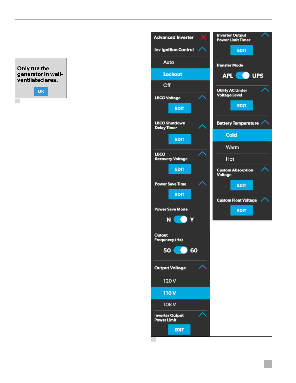
8 Ventilation Alert
• AGS: The Automatic Generator Start (AGS) indicator
shows the status of the auto generator, which can be
either ON or OFF.
There is also a CLEAR AGS button; when external
activity is detected, tap this button to override the
external activity demand and turn the AGS on.
External activity is a mechanism used to disable the
AGS if the generator is manually stopped or started.
This is a safety feature implemented so that if you
manually stop the generator, the AGS system does not
attempt to start it up again. External activity can also
trigger on coach movement or ignition.
The Power screen also has a settings icon that you can tap
to reach the Advanced Inverter Settings screen.
10
9 Advanced Inverter Settings Screens
EN
Page 11
Dometic Interact Operation
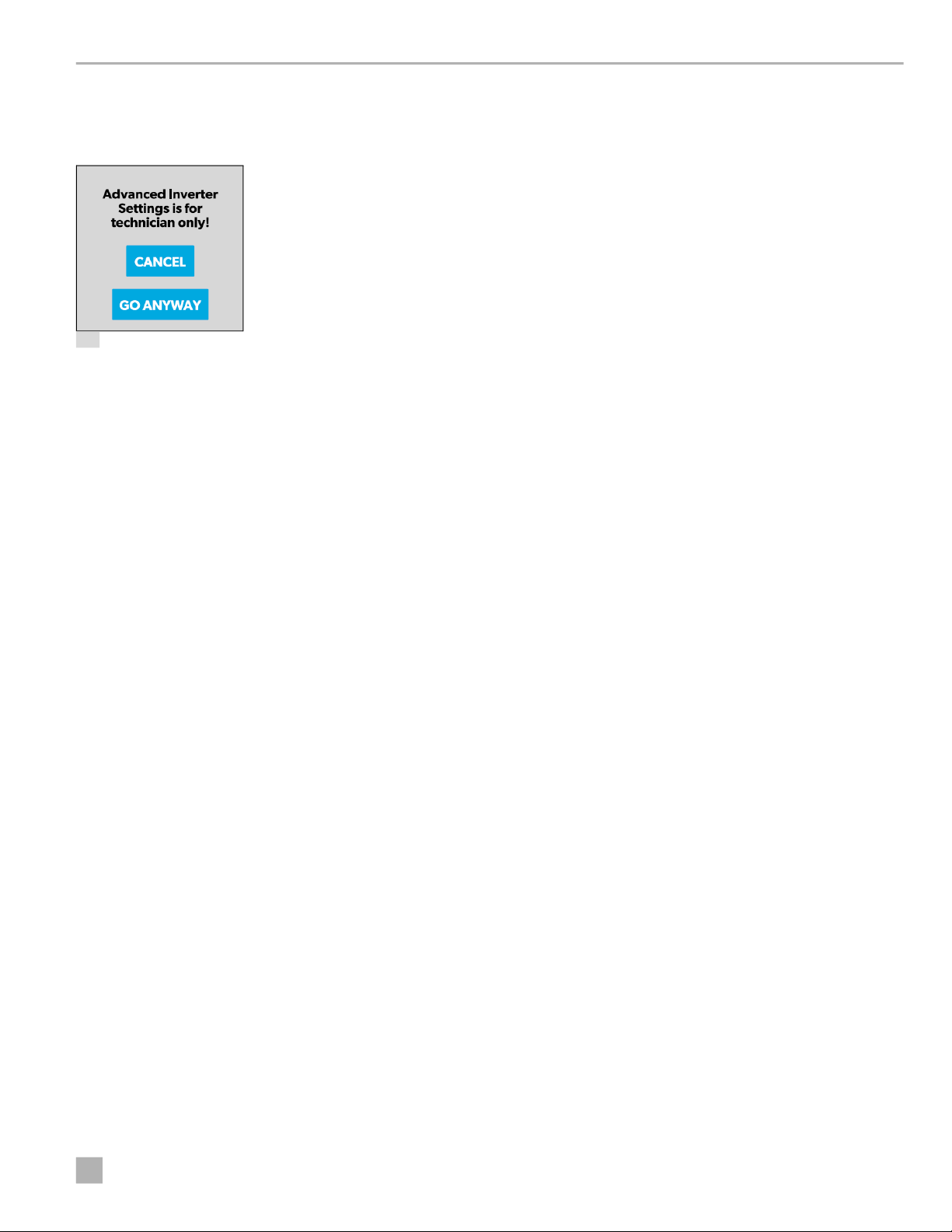
The advanced inverter settings are for technicians only,
and a pop-up message appears when you tap the
advanced inverter icon.
10 Advanced Inverter Settings Notification
Tap the CANCEL button to return to the Power screen, or
tap the GO ANYWAY button to proceed to the
Advanced Inverter screen.
There are some configurable settings available from
I
the inverter LCD display.
From the Advanced Inverter Settings screen, technicians
can control or monitor the following functions by tapping
the expand/contract arrows, toggle buttons, EDIT, and
OK buttons as applicable:
• Inverter Ignition Control
• LBCO Voltage
• LBCO Shutdown Delay Timer
2. Based on the available options for the selected
feature, complete one of the following actions:
– Tap an option from the list.
– Tap the toggle button to activate/deactivate the
feature.
– Tap the EDIT button to view the available settings for
the value.
3. If the EDIT button is selected:
a. Change the value as desired.
b. Tap the OK button to confirm the change and
return to the Advanced Inverter Settings screen.
4. Repeat the previous steps to set the other feature
settings as applicable.
5. After all updates are complete, tap the exit (x) icon to
leave the feature settings mode and return to the
Power screen.
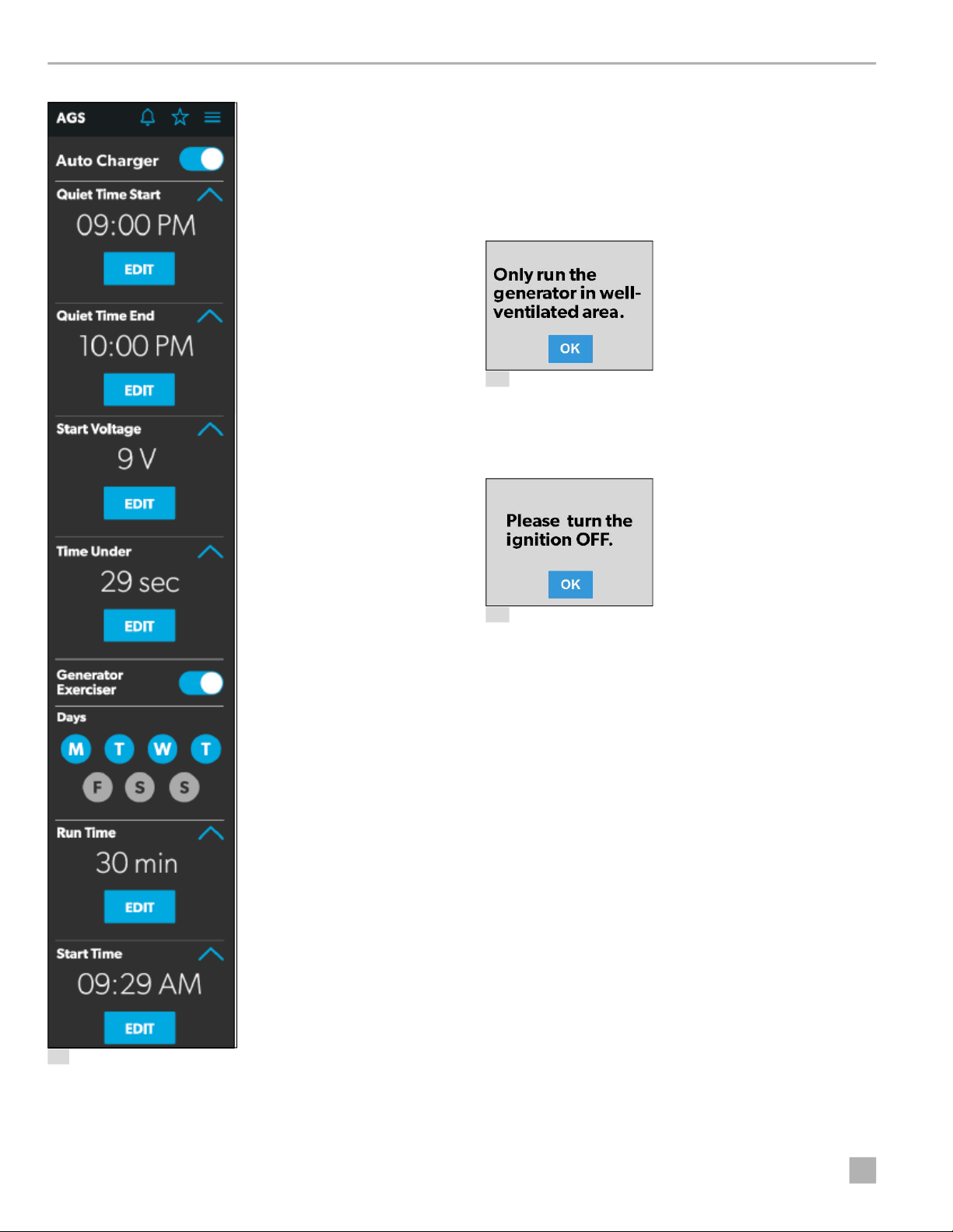
4.1.6 AGS Screen
The AGS (Auto-Gen Start) screen allows you to monitor
and control the automatic generator settings, such as the
scheduled on/off times, scheduled run times, and
voltages.
• LBCO Recovery Voltage
• Power Save Time
• Power Save Mode
• Output Voltage
• Inverter Output Power Limit
• Inverter Output Power Limit Timer
• Transfer Mode
• Utility AC Under Voltage Level
• Custom Absorption Voltage
• Custom Float Voltage
Complete the following steps to change the default value
to a different value:
1. Tap the expand/contract button for the feature
setting that you want to update.
EN
11
Page 12
Operation Dometic Interact
From this screen, you can control and monitor the
following functions:
• Auto Charger: Use this toggle button to enable or
disable the auto charger. The auto charger is disabled
by default. When you enable the auto charger, a popup message appears.
12 Ventilation Alert
The AGS becomes disabled if the ignition is turned on.
If you attempt to enable the auto charger while the
ignition is on, a pop-up message appears.
11 AGS Screen
13 Ignition Alert
The following auto charger settings are available:
– Time Selection: Use the available tumblers (hour
and minute) to set the desired quiet time start and
end times. The generator is turned off automatically
during the specified quiet time.
– Start Voltage: Use the tumbler to set your desired
voltage setting (10 V–12.9 V). The default setting is
10.5 V. The Start Voltage tumbler controls the
threshold voltage under which the AGS must turn
on.
– Time Under: Use the tumbler to set your desired
timer setting (0–10 min). The Time Under tumbler
specifies the timer delay before the AGS starts,
when the system drops below the set threshold
voltage.
• AGS Climate: These options enable the climate
controls, which run the air conditioner and heat pump
of the generator when no shore power is available.
12
EN
Page 13
Dometic Interact Operation
• Generator Exerciser: Use the toggle button to
enable or disable the generator exerciser.
When you enable this setting, the Ventilation Alert
pop-up message appears. The alert message does not
appear when the generator activates based on the set
schedule. The generator runs as scheduled if the
ignition is turned off. If the ignition is turned on during
a particular day that the generator is scheduled to run,
it would skip running the generator that day unless the
ignition is turned off.
The following generator exerciser settings are
available:
– Days: Tap the desired days to specify the days on
which the generator exerciser should run.
– Run Time: This tumbler controls the duration for the
generator exerciser. Use the tumbler to set your
desired time setting (10–2400 minutes).
– Start Time: These tumblers control the time at
which the generator exerciser should start. Use the
available tumblers (hour and minute) to set your
desired time settings.
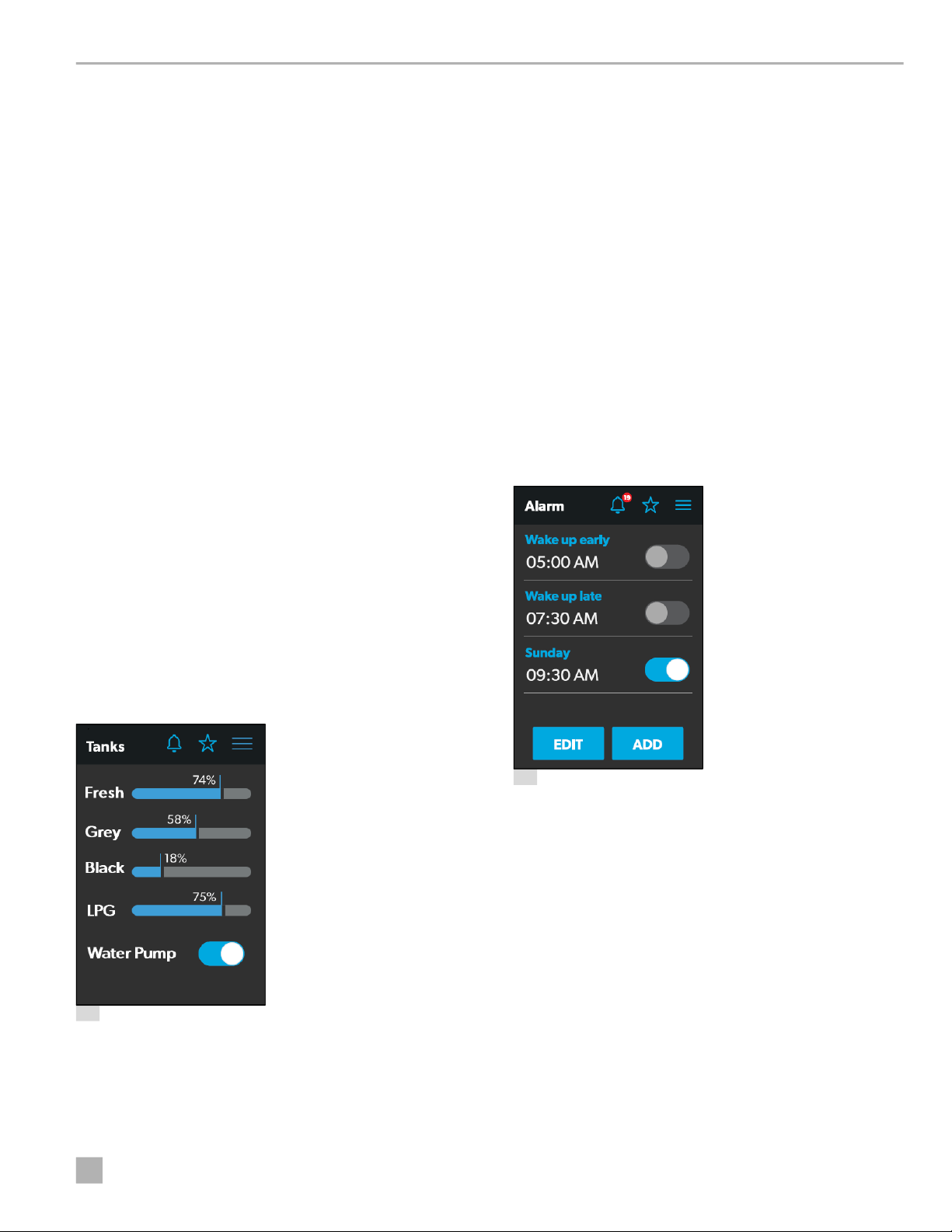
From this screen, you can monitor and control the
following functions:
• Indicator Bars: The horizontal bars indicate the fluid
levels for the various tanks (percent full), which are
monitored continuously by the sensors attached to the
outside of the tanks. These indicators are for
monitoring purposes only and do not have any control
functions.
• Water Pump: Use this toggle button to turn the water
pump on or off. The water pump is deactivated by
default.
4.1.8 Alarms Screen
The Alarms screen allows you to configure alarms for the
system, including alert tones, alarm times, and alarm
names.
4.1.7 Tanks Screen
The Tanks screen allows you to monitor and control the
holding tanks, such as the fresh, gray, and black water
tanks.
14 Tanks Screen
15 Alarms Screen
The Alarms screen is the main screen from which
configured alarms can be monitored, enabled, or
disabled. You can complete the following actions from
this screen:
• Use the toggle button next to an alarm to enable or
disable the alarm.
• Tap the alarm name to open the Alarm Edit window
and edit a configured alarm.
• Tap the add button to open the Pop-Up Time window
and create a new alarm.
When an active alarm triggers, a pop-up window appears
on all displays in the coach along with the sound selected
for the alarm.
EN
13
Page 14
Operation Dometic Interact
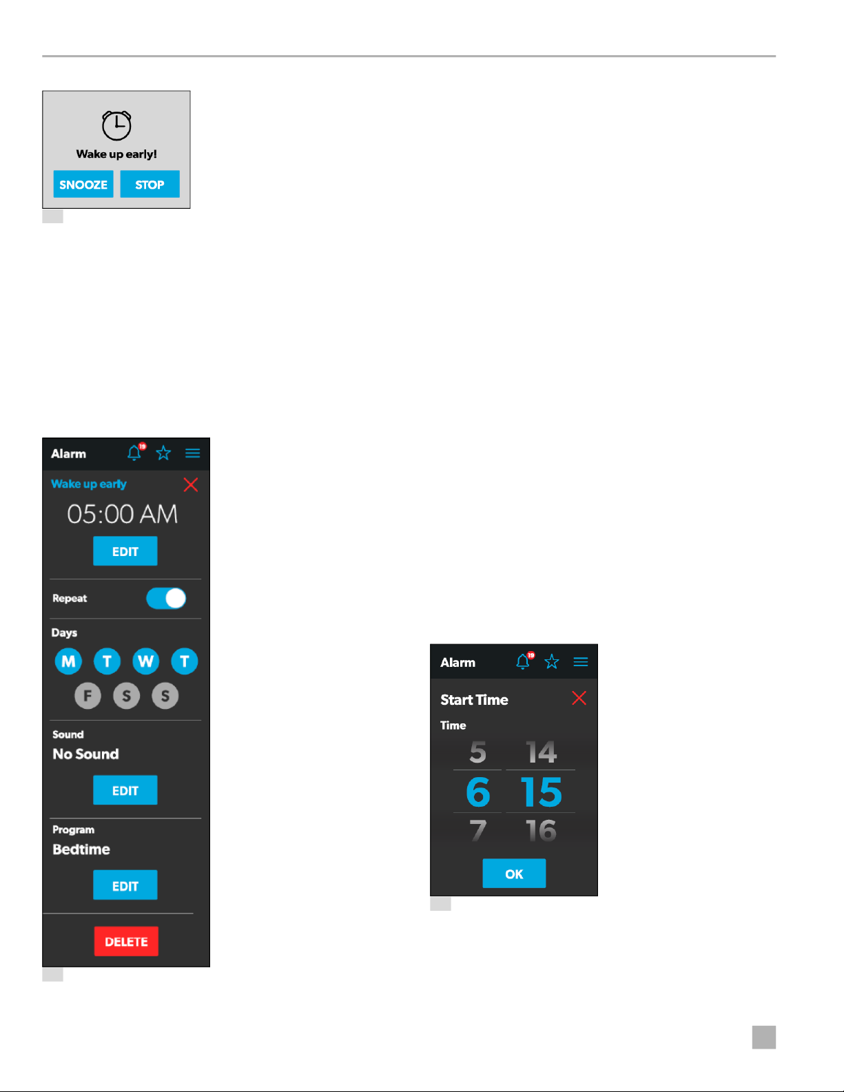
From this window, you can configure or adjust the
following functions:
• Alarm Name: The name of the alarm displays. Tap the
alarm name to open the
Naming window.
• Time Selection: The set time for the alarm displays.
16 Alarm Notification
Tap the EDIT button to open the
Pop-Up Time window.
• Repeat: Use this toggle button to enable or disable a
From any display, you can tap the SNOOZE button on the
pop-up window to delay the alarm for five minutes, or tap
the STOP button to stop the alarm.
repeating alarm based on the days that you choose.
When Repeat mode is enabled, it repeats the alarms
for the days selected.
The following sections provide more information about
configuring new alarms and editing existing alarms.
4.1.8.1 Alarm Edit Window
The Alarm Edit window allows you to configure or alter
the alarms listed on the
Alarms screen.
• Days: Tap the desired days (represented by single
letters) to specify the days on which the alarm will
repeat.
• Sound: The specified sound for the alarm displays.
Tap the EDIT button to open the
Sound Decision
window.
• Program: The specified program for the alarm is
displayed. Tap the EDIT button to open the
Program
Decision window.
• Delete: Tap this button to delete the alarm from the list
of alarms displayed on the
Alarms screen.
4.1.8.2 Pop-Up Time Window
The Pop-up Time window appears when you tap the Time
Selection Edit button from the
Alarm Edit window.
17 Alarm Edit Window
14
18 Pop-Up Time Window
EN
Page 15
Dometic Interact Operation
From this window, you can use the available time
tumblers (hour and minute) to set the time at which the
alarm will trigger. Tap the OK button to save the time
settings and return to the
Alarm Edit window.
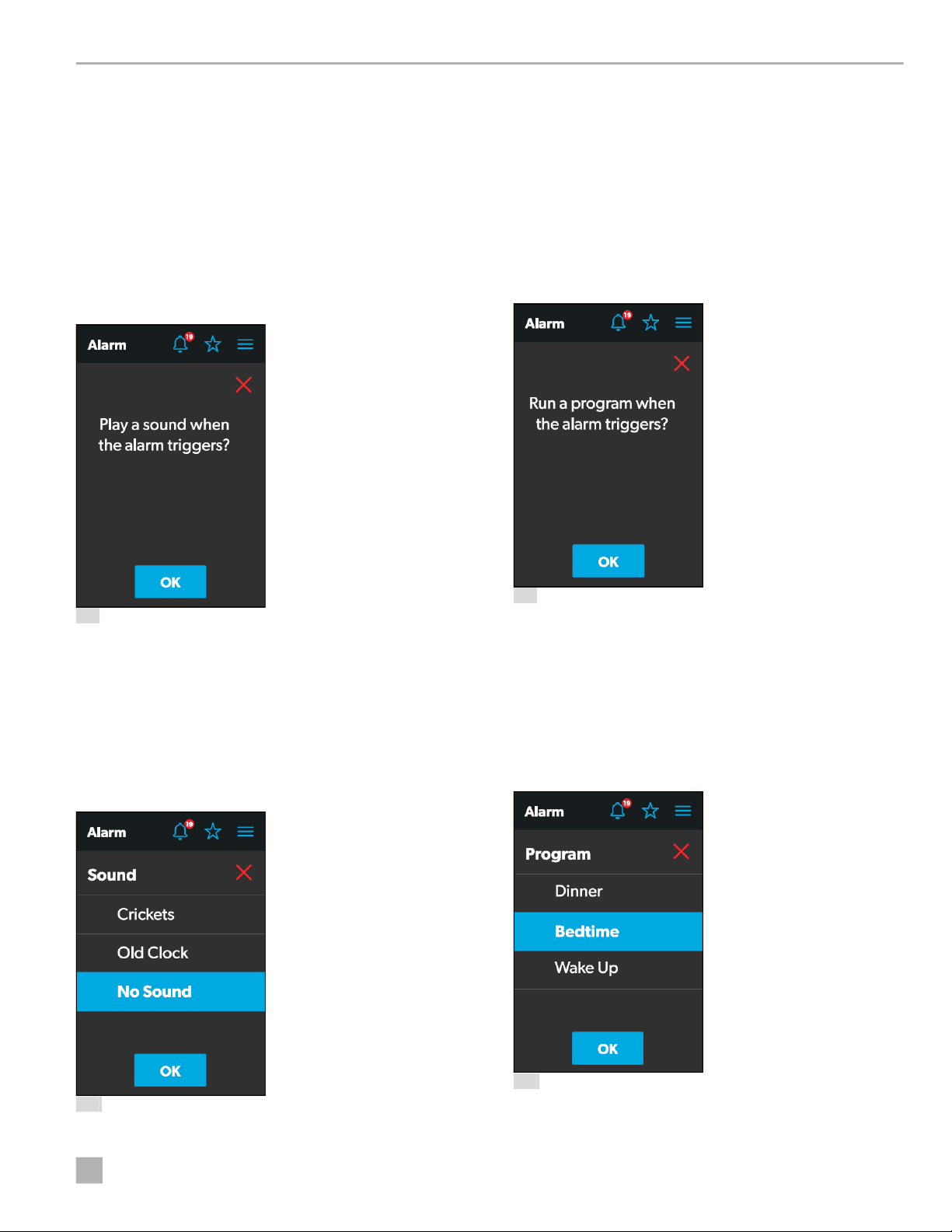
4.1.8.3 Sound Decision Window
The Sound Decision window appears when you tap the
Sound Edit button from the
Alarm Edit window. From this
window, you can specify whether an alert tone should be
applied to an alarm when it triggers.
Choose a sound for the alarm, and then tap the OK button
to save your changes and return to the
Alarm Edit
window.
4.1.8.5 Program Decision Window
The Program Decision window appears when you tap the
Program Edit button from the
Alarm Edit window. From
this window, you can determine whether a program
should run when an alarm triggers.
19 Sound Decision Window
Tap the OK button to confirm that a sound should be used
when the alarm triggers, and the
Sound Selection
window opens.
4.1.8.4 Sound Selection Window
The Sound Selection window allows you to define an alert
tone for an alarm when it triggers.
21 Program Decision Window
Tap the OK button to confirm that a program should run
when the alarm triggers, and the
Program Selection
window opens.
4.1.8.6 Program Selection Window
The Program Selection window allows you to specify a
program that will run when an alarm triggers.
20 Sound Selection Window
EN
22 Program Selection Window
15
Page 16
Operation Dometic Interact
Choose a program for the alarm, and then tap the OK
button to save your changes and return to the
Alarm Edit
window.
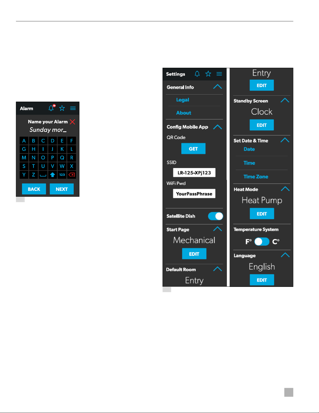
4.1.8.7 Naming Window
The Naming window appears when you tap the alarm
name from the
Alarm Edit window. From this window,
you can specify a title for the alarm. The title of the alarm is
what appears on the
Alarms screen.
4.1.9 Settings Screen
The Settings screen allows you to control and configure
the various aspects of the system and control, such as
languages, screen brightness, and audio levels.
23 Naming Window
From this window, you can complete the actions that are
described in the list that follows.
• Keypad: Use the keypad as desired to create a
descriptive title for the alarm.
• Back: Tap this button to open the Program Decision
window.
• Next: Tap this button to return to the Alarms screen.
24 Settings Screen
Refer to the sections that follow for more information
about the various sections of the Settings screen.
16
EN
Page 17

Dometic Interact Operation
4.1.9.1 General Info Section
Use this section of the Settings screen to find general
legal information and to learn about the system:
• Tap Legal to open the Legal window.
25 Legal Window
• Tap About to open the About window.
1. Tap the GET button to open a window that contains a
scannable QR code, which leads to the mobile
application download from the App Store or Google
Play Store.
27 QR Code Window
2. Tap the SSID text field to specify the SSID that must
be entered when connecting to the system via the
mobile application. The SSID has a 63-character limit
that when exceeded, prompts a pop-up message.
26 About Window
4.1.9.2 Config Mobile App Section
Use this section of the Settings screen to configure the
mobile application connection settings from the touchscreen display:
28 Character Limit Notification
3. Tap the WiFi Pwd text field to specify the password
that must be entered when connecting to the system
via the mobile application. The password has a 32byte limit that when exceeded, prompts a pop-up
message.
29 Password Limit Notification
4.1.9.3 Satellite Dish Option
Use the Satellite Dish toggle button to turn the satellite
dish on or off.
This option may not be available from the Settings
I
screen, as options vary per configuration.
EN
17
Page 18
Operation Dometic Interact
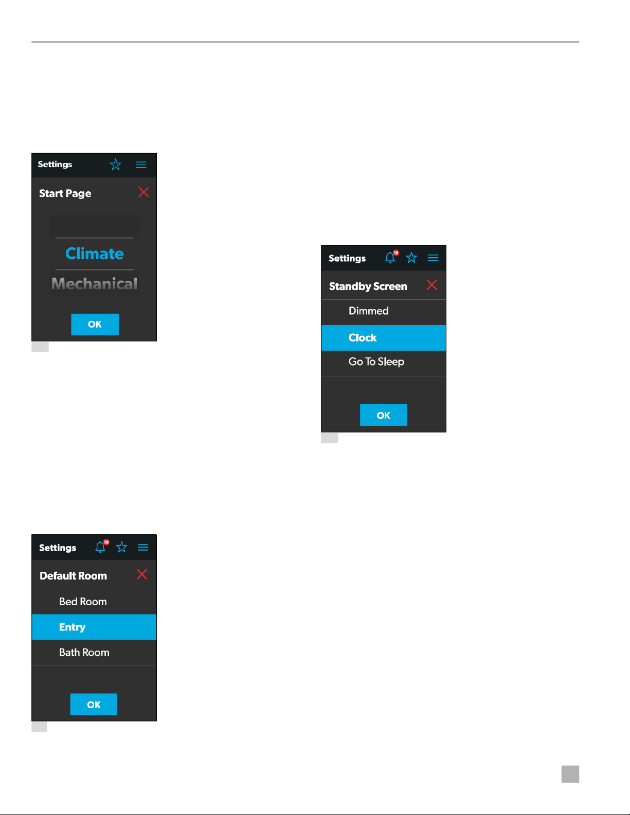
4.1.9.4 Start Page Section
Use this section of the Settings screen to set the default
screen that will display when you are within sensing range
of the proximity sensor:
1. Tap the EDIT button to open the Start Page window.
30 Start Page Window
2. Choose from the list of available rooms (Bedroom,
Entry, or Bathroom).
3. Tap the OK button to save your selection and return
to the
Settings screen.
4.1.9.6 Standby Screen Section
Use this section of the Settings screen to set the screen
that should appear when you are outside of the sensing
range of the proximity sensor:
1. Tap the EDIT button to open the Standby Screen
window.
2. Use the tumbler to choose from a list of all available
screens that you can set as your starting page.
3. Tap the OK button to save your selection and return
to the
Settings screen.
4.1.9.5 Default Room Section
Use this section of the Settings screen to set the default
room that appears on the
Main Navigation screen:
1. Tap the EDIT button to open the Default Room
window.
32 Standby Screen Window
2. Choose from the list of available display options:
– Dimmed: The screen dims to 30% brightness until
the proximity sensor senses movement.
– Clock: The screen displays the Clock screen until
the proximity sensor senses movement. Refer to the
Clock Screen section for more information.
– Go To Sleep: The screen goes black until the
proximity sensor senses movement.
3. Tap the OK button to save your selection and return
to the
Settings screen.
I
When you move into the sensing range of the
proximity sensor, the display will show the start
page that you selected.
31 Default Room Window
18
EN
Page 19
Dometic Interact Operation
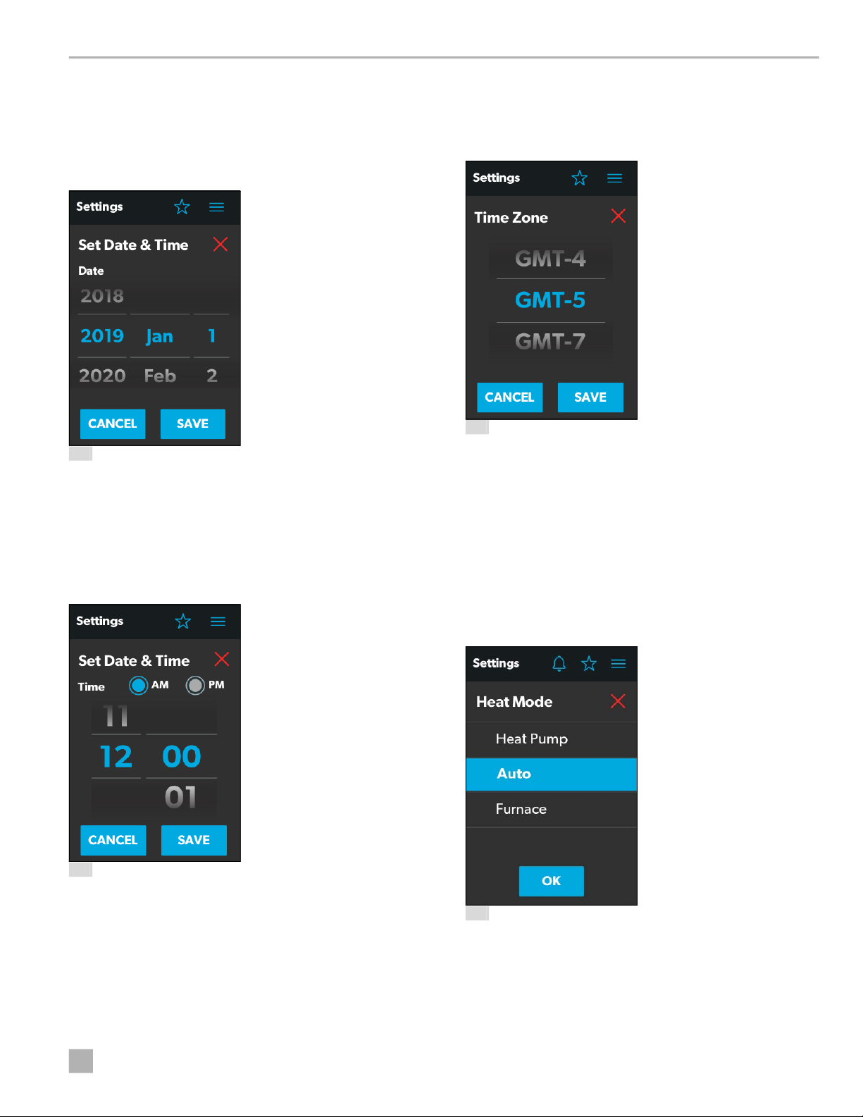
4.1.9.7 Set Date & Time Section
Use this section of the Settings screen to set the current
date and time:
1. Tap Date to open the Date window.
33 Date Window
2. Use the day, month, and year tumblers to set the
current date.
6. Tap the SAVE button to save your selections and
return to the
Settings screen.
7. Tap Time Zone to open the Time Zone window.
35 Time Zone Window
8. Use the tumbler to select your time zone.
9. Tap the SAVE button to save your changes and return
to the
Settings screen.
3. Tap the SAVE button to save your selections and
return to the
Settings screen.
4. Tap Time to open the Time window.
34 Time Window
5. Use the AM/PM radio buttons and the hour and
minute tumblers to set the current time.
4.1.9.8 Heat Mode Section
Use this section of the Settings screen to set the method
of heating:
1. Tap the EDIT button to open the Heat Mode window.
36 Heat Mode Window
I
EN
The AM/PM radio buttons will not appear if the
time format is set to 24-hour.
2. Choose from the list of available heat modes:
– Heat Pump: Only the heat pump runs when the
coach requires heating.
19
Page 20
Operation Dometic Interact
– Auto: The furnace and/or heat pump will run when
the coach requires heating. The furnace will only
turn on if the temperature drops below the set point.
The furnace is used as a secondary boost for the heat
pump if the temperature gets cold enough.
– Furnace: Only the furnace runs when the coach
requires heating.
3. Tap the OK button to save your selection and return
to the
Settings screen.
4.1.9.9 Temperature System Option
Use the Temperature System toggle button to set your
desired temperature readings (in degrees Centigrade or
Fahrenheit).
The side of the toggle button that holds the dot indicates
the current selection.
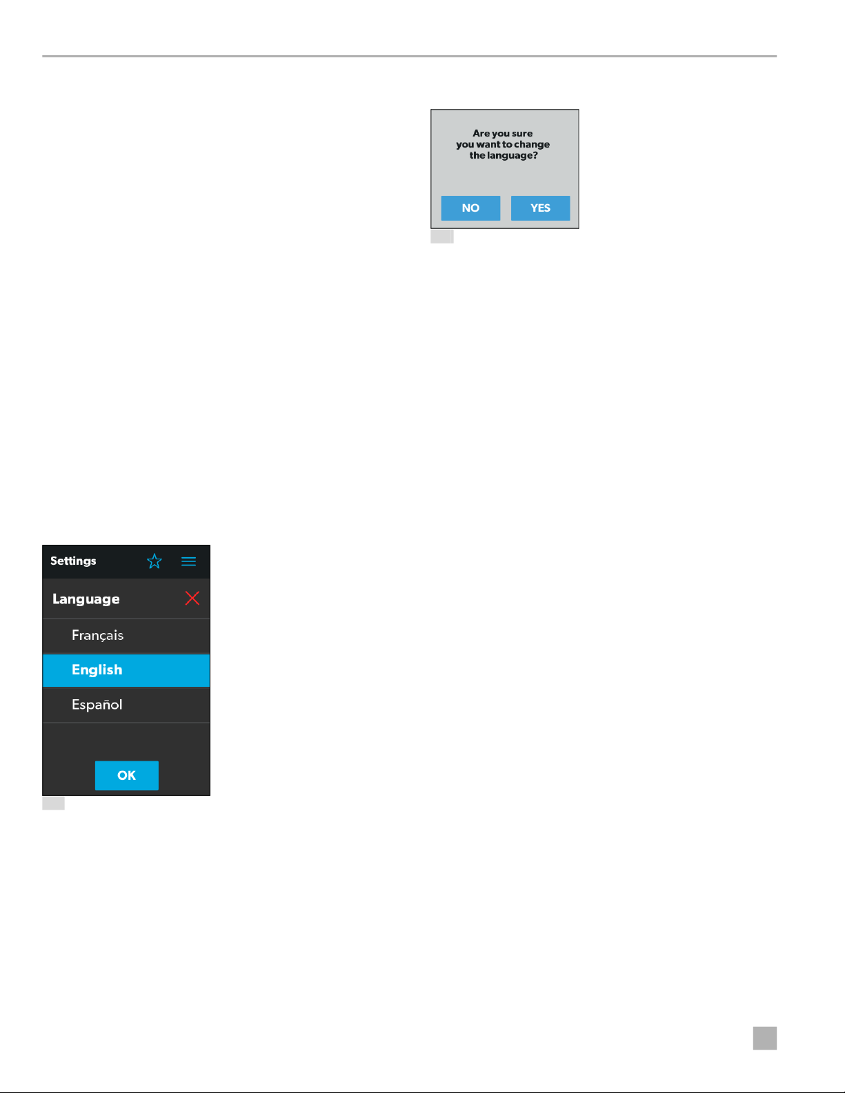
4.1.9.10 Language Section
Use this section of the Settings screen to set the desired
language for all screens on the control:
1. Tap the EDIT button to open the Language window.
3. Tap the OK button, and a pop-up message appears.
38 Language Change Confirmation
4. Tap the YES button to save your selection and return
to the
Settings screen.
4.1.9.11 Brightness Mode Option
Use the Brightness Mode toggle button to choose
between Auto (A) or Manual (M) adjustment modes:
• When the auto option is selected, the brightness is
adjusted according to the ambient light sensor values.
• When the manual option is selected, you can adjust the
screen brightness manually.
4.1.9.12 Screen Brightness Option
Use the Screen Brightness slider to manually set your
desired screen brightness level (shown as a percentage
of full intensity).
37 Language Window
2. Choose from the list of available languages (French,
English, or Spanish).
In order to set the screen brightness, the manual
brightness mode must be selected.
4.1.9.13 Proximity Sensitivity Option
Use the Proximity Sensitivity slider to set your desired
proximity sensor sensitivity level.
The number 1 represents the lowest sensitivity level, and
10 represents the highest sensitivity level.
4.1.9.14 Audio Level Option
Use the Audio Level slider to set your desired audio level
intensity for the control (shown as a percentage of full
intensity).
20
EN
Page 21
Dometic Interact Operation
4.1.9.15 Time Format Option
Use the Time Format toggle button to set your desired
time format (in 12-hour or 24-hour formats).
The side of the toggle button that holds the dot indicates
the current selection.
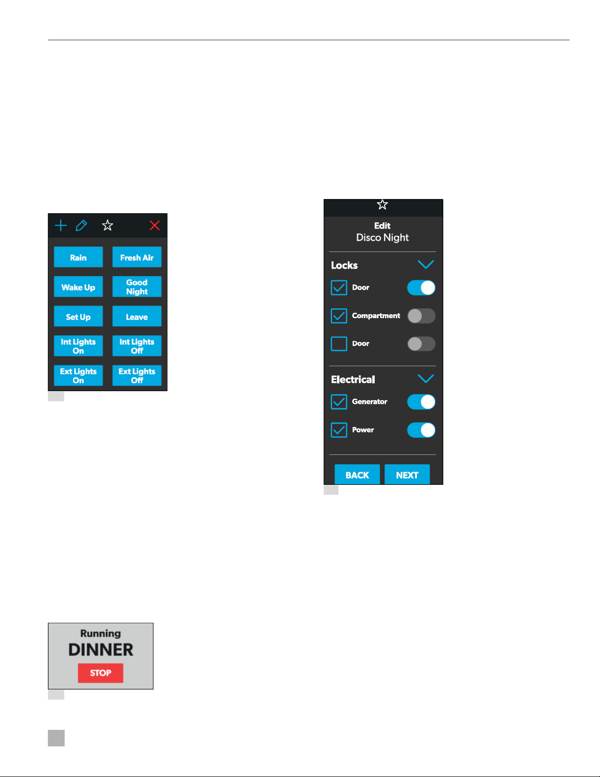
4.1.10 Programs Screen
The Programs screen allows you to monitor, control, and
configure the programs for the system.
• Tap the STOP button to end the program.
Refer to the sections that follow for more information
about configuring new programs and editing existing
programs.
4.1.10.1 New Programs Window
The New Programs window allows you to configure a
new program, which will be listed on the main
Programs
screen.
39 Programs Screen
The Programs screen is the main screen from which
configured programs can be monitored, enabled, or
disabled. You can complete the following actions from
this screen:
• Tap the exit (x) icon to close the Programs screen and
return to the previous screen.
• Tap the plus (+) icon to open the New Programs
window and create a new program.
• Tap the pencil icon to open the Program Settings
window.
• Tap any preexisting program button to start running
the program, and a pop-up window appears to
indicate that the program is running.
40 Running Program Notification
41 New Programs Window
From this window, you can configure or adjust the
following functions:
• Locks: Use the available toggle buttons and check
boxes in the Locks section to select the options that
you want to control with the new program.
• Electrical: Use the available toggle buttons and check
boxes in the Electrical section to select the options that
you want to control with the new program.
• Back: Tap this button to cancel your changes and
return to the main
Programs screen.
• Next: Tap this button to save your changes and open
the
Naming Program window.
EN
21
Page 22

Operation Dometic Interact
4.1.10.2 Program Settings Window
The Program Settings window allows you to select a
program for editing or delete it.
42 Program Settings Window
From this window, you can complete the following
actions:
4.1.10.3 Edit Program Window
The Edit Program window allows you to configure or
adjust the settings for your desired program.
• Tap the pencil icon on a program to open the Edit
Program window.
• Tap the exit (x) icon on the program to delete the
program. A pop-up message appears.
43 Running Program Notification
– Tap the No button to close the pop-up window
without any changes.
– Tap the Yes button to cancel running the program
and delete it from the system.
44 Edit Program Window
From this window, you can configure or adjust the
following functions:
• Locks: Use the available toggle buttons and check
boxes in the Locks section to select the options that
you want to control with the program.
• Electrical: Use the available toggle buttons and check
boxes in the Electrical section to select the options that
you want to control with the program.
• Back: Tap this button to cancel your changes and
return to the main
Programs screen.
• Next: Tap this button to save your changes and open
the
Naming Program window.
22
EN
Page 23

Dometic Interact Operation
4.1.10.4 Naming Program Window
The Naming Program window allows you to configure or
adjust the title of your desired program.
45 Naming Program Window
From this window, you can complete the following
actions:
From this window, you can complete the following
actions:
• Back: Tap this button to return to the Naming Program
window.
• Save: Tap this button save all updates to the program.
Afterwards, the program will appear in the list of
programs displayed on the main
Programs screen.
4.1.11 Fuses Screen
The Fuses screen allows you to monitor and control the
fuses for the various system components.
• Keypad: Use the keypad as desired to create a
descriptive title for the program.
• Back: Tap this button to return to the Edit Program
window.
• Next: Tap this button to open the Save Program
window.
4.1.10.5 Save Program Window
The Save Program window allows you to confirm and
save your program changes.
47 Fuses Screen
Each controlled component includes a toggle button
indicating the fuse status: OK or blown.
46 Save Program Window
EN
When the system detects a high inrush current or overvoltage condition, the software blows the fuse for that
particular output.
23
Page 24

Operation Dometic Interact
Use the toggle button to reset a blown fuse, which sets it
to the enabled (OK) state.
All of the blown fuses appear at the top of the list,
followed by a list of active fuses.
When a fuse blows, the system produces a notification by
showing a number beside the bell icon at the top of each
screen. The system also plays a sound to notify you.
The number on the notification bell icon remains until you
open the Notifications screen and close all notifications,
one-by-one.
Refer to the Notifications Screen section for more
information.
4.1.12 Bedroom Screen
The Bedroom screen allows you to monitor and control
the available components within the bedroom area of
your RV, such as the climate and lights.
Not all systems will include this screen. Control
I
screens vary according to specific system
configurations and available components.
• Lights: Use the toggle button for the desired light
source to turn it off or on. The light source brightness is
indicated as a percentage of the maximum intensity.
Tap the brightness indicator for the desired light to
adjust the intensity via vertical slider.
4.1.13 Bathroom Screen
The Bathroom screen allows you to monitor and control
the available components within the bathroom area of
your RV, such as ventilation, water pump, and lights.
Not all systems will include this screen. Control
I
screens vary according to specific system
configurations and available components.
48 Bedroom Screen
From this screen, you can monitor and control the
following functions:
• Temperature: Use the power toggle button to turn
the climate controls on or off. When the power button
is on, you can use the tumbler to select your desired
temperature.
24
49 Bathroom Screen
From this screen, you can monitor and control the
following functions:
• Lights: Use the toggle button for the desired light
source to turn it off or on. The light source brightness is
indicated as a percentage of the maximum intensity.
Tap the brightness indicator for the desired light to
adjust the intensity via vertical slider.
• Fan: Use the power toggle button to turn the fan motor
on or off.
I
The lid must be open before the fan motor turns
on. If the lid is closed when you attempt to turn the
fan motor on, the lid will open automatically.
EN
Page 25

Dometic Interact Operation
• Lid Control: Tap the Open or Close button to open or
close the lids. A white outline around the button
indicates the status of the lid.
• Water Pump: Use this toggle button to turn the water
pump on or off.
4.1.14 Entry Screen
The Entry screen allows you to monitor and control the
available components within the entry area of your RV,
such as lighting and awnings.
Not all systems will include this screen. Control
I
screens vary according to specific system
configurations and available components.
51 Parking Brake Alert
The Awning buttons function as follows:
– Tap the plus button (+) to extend the awning or the
minus button (–) to retract the awning, and a pop-up
message appears (assuming the parking brake is
engaged).
52 Awning Clear Message
– After you have verified that the awning is clear of
obstructions, tap the OK button. The awning is now
ready to extend or retract.
4.1.15 Clock Screen
50 Entry Screen
From this screen, you can monitor and control the
following functions:
• Entry Lighting: Use the toggle button for the desired
light source to turn it off or on.
I
• Awnings: The Awning buttons allow you to extend or
The All Entry Lights toggle button controls all three
entry light sources (porch, awning, and lounge).
retract the awning. Awnings will have no control unless
the parking brake is engaged.
If you attempt to extend or retract the awnings while
the parking brake is not engaged, an alert appears.
The Clock screen allows you to monitor various system
statuses, such as temperatures, time and date, and
humidity.
This screen appears when the proximity sensor is out of
the threshold distance (sensing range). For this screen to
appear in standby mode, you must select the Clock
standby option from the
Settings screen.
EN
25
Page 26

Operation Dometic Interact
53 Clock Screen
From this screen, you can monitor the following system
statuses:
• Use Temperature: This inside and outside
temperatures are presented in either degrees
Centigrade or Fahrenheit, which you can define from
the
Settings screen.
• Time and Date: The current time and date are
displayed in the middle of the screen.
• Humidity: The humidity is shown as a percentage,
coming from the onboard humidity sensor reading.
• Battery Levels: The battery level indicator monitors
and displays the battery voltage level.
4.1.16 Notifications Screen
The Notifications screen allows you to monitor system
fault status messages, such as blown fuse notifications.
54 Notification Screen
From this screen, you can complete the following actions:
• View and Clear Notifications: Notifications appear
with a banner when you open the Notifications screen.
– To clear an individual message, tap the exit (x) icon
for that message.
– To clear all messages, tap the CLEAR ALL button.
• View Diagnostics Information: You can view
diagnostics information for each notification.
– To view the diagnostics information for the
notifications, tap the SHOW DM RVC button. The
Diagnostics Message window appears.
This screen can be reached by tapping the bell icon at the
top of any screen.
26
55 Diagnostics Message Window
– To clear an individual message, tap the exit (x) icon
for that message.
– To clear all messages, tap the CLEAR ALL button.
EN
Page 27

Dometic Interact Operation
4.2 Mobile Application Navigation and Use
This section describes how to use Dometic Interact from
the downloadable mobile application. Refer to
Screen Navigation and Use to learn how to operate the
control using the onboard touch-screen display.
The mobile application is provided for your
I
convenience. It is not required in order to use
Dometic Interact.
4.2.1 Prerequisites
Before you can connect to Dometic Interact with a mobile
device, you must first download the System Control
application onto your device.
Touch-
3. Locate and connect to the Wi-Fi network named LR-
125.
56 System Control App
• To download the application for Apple devices, visit
the
App Store.
• To download the application for Android devices, visit
the Google Play Store.
After you have downloaded the application onto your
mobile device, you can proceed to make the initial
connection to the control.
4.2.2 Initial Connection
Complete the following steps to make the initial
connection to the control from your mobile device:
1. Move into the vicinity of the control to ensure
successful connection.
2. Open your device settings and search for available
Wi-Fi networks.
57 Wi-Fi Networks
4. Enter the default password, which is
YourPassPhrase.
You should now be successfully connected to Dometic
Interact. You can proceed to change the password
settings, if desired.
4.2.3 Password Settings
Complete the following steps to change the password:
1. Tap the Settings icon once.
2. Tap Set URL, and then enter 192.168.8.1.
EN
27
Page 28

Operation Dometic Interact
3. Tap the Settings icon once again, and then tap
Network Page.
The following screen appears, where you can update
your password as desired.
58 Network Configuration Menu
59 Network Configuration Update Menu
4. After your password settings are updated, restart
your Wi-Fi server and login with the new credentials.
4.2.4 Navigation and Use
After successful connection to the Dometic Interact Wi-Fi
network, you are ready to begin using your mobile device
to control the available components within your control
configuration.
The mobile application landing page includes the
following navigation options:
28
60 Landing Page Navigation
EN
Page 29

Dometic Interact Operation
From the landing page, you can tap the following tabs to
reach the desired screen:
• Main Screen: Tap this tab to reach the Main
Navigation screen. Once you reach the Main
Navigation screen, you can navigate to and use the
main screens just as described in the
Touch-Screen
Navigation and Use section.
• System Configuration: Tap this tab to reach the
System Configuration screen, where you can elect to
show metric values, or enable the splash screen.
• Update Software: Tap this tab to reach the Update
WiFi Server Software screen, where you can view and
manage the current software versions.
61 System Configuration Screen
62 Update WiFi Server Software Screen
EN
29
Page 30

Maintenance Dometic Interact
• View Log: Tap this tab to reach the LR 125 Boot Log
screen, where you can choose to load the boot log for
the Wi-Fi server.
5.1 Care and Cleaning
!
WARNING: FIRE AND/OR ELECTRICAL SHOCK
HAZARD
Do not allow water to splash on or pour into a
powered unit. Failure to obey this warning could
result in death or serious injury.
NOTICE: Do not use abrasive cleaning materials or
harsh chemicals on the touch-screen display, or damage
to the product can occur.
If the touch-screen display becomes dirty, clean it with a
soft, dry cloth, or use compressed air to loosen debris
from the external orifices.
To remove hard dirt or grime, a slightly damp cloth with
non-abrasive cleaning product is acceptable; however,
take care not to damage the touch-screen display.
5.2 Preventive Maintenance
63 Boot Log Screen
• Close: Tap this tab to close the mobile application.
5 Maintenance
!
WARNING: FIRE AND/OR ELECTRICAL SHOCK
HAZARD
Use care when diagnosing, repairing, adjusting,
and/or cleaning components on a powered unit.
Failure to obey this warning could result in death or
serious injury.
This section describes how to care for and maintain
Dometic Interact. Refer to the following sections for
information about care, cleaning, and preventive
maintenance of the product.
Use the following tips to ensure that your control
continues to work properly:
• Ensure that the touch-screen display and PCB are
operated between -4 °F to 140 °F (-20 °C to 60 °C).
• Ensure that you power on the control system
occasionally during extended periods of non-use.
6 Troubleshooting
!
WARNING: FIRE AND/OR ELECTRICAL SHOCK
HAZARD
Use care when diagnosing, repairing, adjusting,
and/or cleaning components on a powered unit.
Failure to obey this warning could result in death or
serious injury.
This section describes how to troubleshoot common
errors that may be encountered on Dometic Interact.
Refer to your inverter operating manual for
I
troubleshooting information and to obtain customer
service center information. Contact the
manufacturer customer service department for
inverter-related issues.
30
EN
Page 31

Dometic Interact Disposal
The table that follows describes some common errors
that may be encountered with the control, their possible
causes, and the recommended corrective actions.
Error Possible Cause Recommended Corrective Action
There is power loss to Dometic
Interact.
The screen does not wake up. You are not within range of the display
The coach lights are not turning on. There is a blown software fuse, or the LED
The AC will not turn on or off. The AC is in a time-delayed start up, or the
You are unable to locate or connect
to the LR-125 Wi-Fi server.
There is a water pump failure. There is a blown software fuse. Examine the Dometic Interact Fuses screen and
There is a satellite dish failure. There is a blown software fuse, or the satel-
The touch-screen is unresponsive. The system might be frozen. Reboot the system by interrupting the power sup-
There is audio trouble. The audio level is set too low. Increase the default audio level in the Settings
The tank level readings are
inaccurate.
The generator fails to exercise. The AGS is turned off, the ignition safety
The fan will not turn on, the fan lid
will not open or close, or the fan lid
closes by itself.
There is too much load on the circuit. Recycle power to the LCD by turning the breaker
proximity sensor.
light needs to be replaced.
AC circuit breaker has tripped.
You are not within range of the LR-125
Wi-Fi module.
lite dish is disabled.
The RV is not level or stationary. Bring the RV to a complete stop and ensure that it
interlock is enabled, or the settings are
incorrect.
The system is frozen, or the rain sensor
made the lids close and the fan turn off.
Contact Dometic Customer Service at 1-800-544-4881,
or email
customersupportcenter@dometic.com for any
other assistance.
for Dometic Interact on and then back off.
Move closer to the LCD screen, or tap it once to
turn it on.
Examine the Dometic Interact Fuses screen and
reset the blown fuse, or replace the LED bulb.
The AC can take up to three minutes to respond to
on/off commands.
Reset the circuit breaker, if needed.
Seek a stronger Wi-Fi signal.
reset the blown fuse, if applicable.
Examine the Dometic Interact Fuses screen and
reset the blown fuse, or enable the satellite dish in
Settings screen.
the
ply for ten seconds.
screen, or reboot the system.
is level.
Turn on the AGS, remove the key from the vehicle
ignition, or adjust the time settings.
Reboot the system by interrupting the power supply for ten seconds. Verify if the fan has a rain
sensor (Fan-Tastic fan model 7350 only).
7 Disposal LIMITED ONE-YEAR WARRANTY
Place the packaging material in the appropriate
M
recycling waste bins, whenever possible. Consult a
local recycling center or specialist dealer for details
about how to dispose of the product in accordance
with all applicable national and local regulations.
EN
LIMITED ONE-YEAR WARRANTY AVAILABLE AT
WWW.DOMETIC.COM/WARRANTY.
IF YOU HAVE QUESTIONS, OR TO OBTAIN A COPY OF
THE LIMITED WARRANTY FREE OF CHARGE,
CONTACT:
DOMETIC CORPORATION
CUSTOMER SUPPORT CENTER
1120 NORTH MAIN STREET
ELKHART, INDIANA, USA 46514
1-800-544-4881 OPT 1
31
Page 32

Sommaire Dometic Interact
Liste des centres de service et des revendeurs
Visiter : www.dometic.com
Lire attentivement ces instructions. Ces instructions DOIVENT rester avec ce produit.
Sommaire
1 Explication des symboles et
des consignes de sécurité . . . . . . . . . . . . . . . . 33
1.1 Reconnaître les consignes de sécurité . . . . . . 33
1.2 Comprendre les mots-indicateurs. . . . . . . . . . 33
1.3 Directives supplémentaires . . . . . . . . . . . . . . . 33
1.4 Messages de sécurité d’ordre général . . . . . . 33
2 Informations générales . . . . . . . . . . . . . . . . . . 34
2.1 Caractéristiques principales . . . . . . . . . . . . . . 34
3 Indication . . . . . . . . . . . . . . . . . . . . . . . . . . . . . 34
4 Mode d’emploi. . . . . . . . . . . . . . . . . . . . . . . . . 35
4.1 Navigation et utilisation de l’écran tactile. . . . 35
4.1.1 Écran de navigation principal et icônes35
4.1.2 Écrans Climate (Climat) . . . . . . . . . . . . 36
4.1.3 Écran Mechanical (Mécanique) . . . . . 37
4.1.4 Écran Lights (Lumières) . . . . . . . . . . . . 39
4.1.5 Écran Power (Alimentation). . . . . . . . . 40
4.1.15 Écran Clock (Horloge). . . . . . . . . . . . . 60
4.1.16 Écran Notifications. . . . . . . . . . . . . . . . 60
4.2 Navigation et utilisation de
l’application mobile . . . . . . . . . . . . . . . . . . . . . .61
4.2.1 Conditions préalables . . . . . . . . . . . . . .61
4.2.2 Première connexion . . . . . . . . . . . . . . .61
4.2.3 Paramètres du mot de passe. . . . . . . . 62
4.2.4 Navigation et utilisation. . . . . . . . . . . . 62
5 Maintenance . . . . . . . . . . . . . . . . . . . . . . . . . . . 64
5.1 Entretien et nettoyage . . . . . . . . . . . . . . . . . . . 64
5.2 Maintenance préventive . . . . . . . . . . . . . . . . . 64
6 Dépannage . . . . . . . . . . . . . . . . . . . . . . . . . . . . 64
7 Élimination . . . . . . . . . . . . . . . . . . . . . . . . . . . . 66
GARANTIE LIMITÉE DE UN AN. . . . . . . . . . . . . . . 66
32
4.1.6 Écran AGS . . . . . . . . . . . . . . . . . . . . . . 43
4.1.7 Écran Tanks (Réservoirs) . . . . . . . . . . . 45
4.1.8 Écran Alarms (Alarmes) . . . . . . . . . . . . 46
4.1.9 Écran Settings (Paramètres) . . . . . . . . 49
4.1.10 Écran Programs (Programmes) . . . . . . 54
4.1.11 Écran Fuses (Fusibles) . . . . . . . . . . . . . 57
4.1.12 Écran Bedroom (Chambre). . . . . . . . . 58
4.1.13 Écran Bathroom (Salle de bain). . . . . . 58
4.1.14 Écran Entry (Entrées) . . . . . . . . . . . . . . 59
FR
Page 33

Dometic Interact Explication des symboles et des consignes de sécurité
1 Explication des symboles et des consignes de sécurité
Ce manuel contient des consignes de sécurité et des
instructions pour aider l’utilisateur à éliminer ou réduire le
risque d’accidents et de blessures.
1.1 Reconnaître les consignes de sécurité
D
C’est le symbole d’alerte à la sécurité.
Il signale des risques de blessures physiques. Obéir
à tous les messages de sécurité qui suivent ce
symbole pour éviter les risques de blessures ou de
mort.
1.2 Comprendre les mots-indicateurs
Un symbole de sécurité et/ou un mot-clé identifient les
messages de sécurité et indiquent la gravité du danger.
D
DANGER!
Indique une situation extrêmement dangereuse qui
entraînera la mort ou des blessures graves si elle
n’est pas évitée.
1.3 Directives supplémentaires
Pour réduire les risques d’accident et de blessure,
veuillez respecter les directives suivantes avant de faire
fonctionner cet appareil
• Lire et suivre toutes les consignes de sécurité et les
instructions.
• Lire et comprendre ces instructions avant d’utiliser ce
produit.
• L’installation doit se conformer à tous les codes locaux
ou nationaux applicables, y compris la toute dernière
édition des normes suivantes
États-Unis
– ANSI/NFPA70, Code national de l’électricité (CNE)
– ANSI/NFPA 1192, Code des véhicules récréatifs
– ANSI Z21.57, Code des véhicules récréatifs
Canada
– CSA C22.1, Parties l et ll, Code canadien de
l’électricité
– CSA Z240 RV Series, véhicules récréatifs
:
:
1.4 Messages de sécurité d’ordre
!
AVERTISSEMENT :
Indique une situation potentiellement dangereuse
qui entraînera la mort ou des blessures graves si elle
n’est pas évitée.
ATTENTION :
!
Indique une situation potentiellement dangereuse
qui entraînera la mort ou des blessures graves si elle
n’est pas évitée.
AVIS : Il est utilisé pour traiter des pratiques non liées à
des blessures physiques.
Indique des informations supplémentaires qui ne
I
sont pas liées aux dangers physiques.
général
!
AVERTISSEMENT : DANGER D’INCENDIE,
D’IMPACT, ET/OU D’EXPLOSION
Le non-respect de ces avertissements pourrait
entraîner de graves blessures, voire la mort
• Utiliser uniquement des pièces et composants de
rechange Dometic spécifiquement approuvés pour
une utilisation avec cet appareil.
• Faire attention en diagnostiquant et/ou ajustant les
composants d’un appareil électrique.
• Ne pas modifier ce produit d’une quelconque
manière. Les modifications peuvent être extrêmement
dangereuses.
• Ne pas autoriser les enfants à jouer avec ce produit ou
avec les commandes fixes (le cas échéant).
:
FR
33
Page 34

Informations générales Dometic Interact
2 Informations générales
Dometic Interact fournit un concentrateur de contrôle et
de surveillance central pour les appareils de votre
véhicule récréatif (VR). Tous les écrans ACL du VR
communiquent entre eux en continu via le bus RV-C.
Lorsqu’un écran ACL est en panne, les autres peuvent
continuer à fonctionner.
Dometic Interact ne remplace pas les contrôleurs
matériels réels des systèmes à l’intérieur du véhicule;
il
s’agit d’un écran qui envoie les signaux et les commandes
à divers composants (tels que les boîtes de chargement)
en ce qui concerne les actions à entreprendre.
Le système Dometic Interact vous permet de :
• Contrôler le climat, l’éclairage, les auvents,
les
coulisses, les systèmes d’alimentation en eau,
les
serrures de porte et les générateurs depuis des
emplacements pratiques dans et autour de votre
véhicule.
• Surveiller l’état des niveaux des réservoirs d’eau, des
niveaux de gaz propane et de la batterie depuis
n’importe quel endroit.
• Contrôle et surveillance des fonctions vitales et
pratiques de votre véhicule récréatif, telles que
– Lumières
– Climat
– Générateur
– Onduleur
– Réservoirs d’eau
– Pompe à eau
– Auvent
– Réveils
– Batterie du véhicule
:
3 Indication
Dometic Interact est conçu pour être utilisé avec les
dispositifs de contrôle et/ou de surveillance existants
dans votre véhicule récréatif. Il crée un concentrateur
central que vous pouvez utiliser pour contrôler et
surveiller efficacement vos appareils, via l’écran tactile
intégré ou depuis votre application mobile.
• Prédire l’utilisation de composants intégrés.
La
technologie d’utilisation prédictive fournit à l’écran
des rapports sur les ressources vitales en eau et en
énergie, et détermine le moment où vous devriez
envisager de remplir ou de recharger.
2.1 Caractéristiques principales
Dometic Interact présente les caractéristiques et
avantages suivants lorsqu’il est intégré à votre VR
• Écran tactile pratique de 3,5 po (89 mm)
• Contrôle de réseau sans fil et application mobile
• Interfaces à un ou plusieurs écrans
• Commande à une touche pour les modes
programmables par l’utilisateur, tels que Home
(Présent), Away (Absent) et Sleep (Veille)
• Touche haptique et retour sonore
• Utilisation prédictive de l’écran
:
Le fabricant n’endosse aucune responsabilité en cas de
dommages dans les cas suivants
• Assemblage ou branchement incorrect
• Endommagement du produit résultant des influences
mécaniques et d’une tension excessive
• Altération du produit sans la permission expresse
du
fabricant
• Utilisation à d’autres fins que celles décrites dans le
manuel d’utilisation
Dometic Corporation se réserve le droit de modifier
l’apparence et les caractéristiques techniques de
l’appareil sans préavis.
:
34
FR
Page 35

Dometic Interact Mode d’emploi
4 Mode d’emploi
!
AVERTISSEMENT : DANGER D’INCENDIE
ET/OU D’IMPACT.
Le non-respect de ces avertissements pourrait
entraîner de graves blessures, voire la mort
• Éviter le fonctionnement incorrect de l’appareil.
Se
reporter aux manuels d’utilisation des produits
spécifiques contrôlés par cet appareil pour
comprendre et respecter les consignes de sécurité
applicables.
• N’autoriser personne (y compris les enfants) ayant des
capacités physiques, sensorielles ou mentales
réduites, ou un manque d’expérience et de
connaissances, à utiliser ce produit, à moins qu’un
contrôle ou des instructions relatives à l’utilisation de
ce produit aient été donnés par une personne
responsable de leur sécurité.
AVIS : Vous pouvez utiliser plusieurs écrans pour différentes
opérations en même temps, mais évitez d’effectuer une
seule opération à partir de plusieurs écrans.
:
Se reporter à Navigation et utilisation de l’application
mobile pour savoir comment utiliser les contrôles à l’aide
de l’application mobile.
Les écrans présentés dans cette section varient
I
en
fonction des appareils disponibles et de la
disposition de votre véhicule récréatif.
4.1.1 Écran de navigation principal
icônes
et
L’écran de navigation principal est l’écran de destination
par défaut que vous utiliserez pour naviguer dans les
différentes zones du contrôle.
Dometic Interact peut être utilisé à partir de l’écran tactile
intégré ou via l’application mobile (téléchargeable sur la
plupart des appareils mobiles).
Se reporter aux sections suivantes pour plus d’informations
sur la navigation et l’utilisation sur les écrans tactiles et
mobiles, y compris des informations sur
• Écrans et boutons de l’interface utilisateur
• Fonctionnalité de contrôle et de surveillance
• Pré-requis (mobile uniquement)
:
4.1 Navigation et utilisation
l’écran tactile
de
Cette section explique comment utiliser Dometic Interact
à partir de l’écran tactile.
1 Écran de navigation principal
L’écran de navigation principal donne accès aux écrans
suivants
• Climate (Climat)
• Mechanical (Mécanique)
• Lights (Lumières)
• Power (Alimentation)
• AGS
• Tanks (Réservoirs)
• Alarms (Alarmes)
• Settings (Paramètres)
:
FR
35
Page 36

Mode d’emploi Dometic Interact
• Programs (Programmes)
• Fuses (Fusibles)
• Rooms (Pièces)
• Notifications
Le tableau suivant décrit les boutons utilisés pour la
navigation générale des différents écrans et pour la
sélection des paramètres.
Bouton Description
Appuyer sur cette icône pour modifier la
disposition de l’écran de navigation principale
mode liste.
en
Appuyer sur cette icône pour modifier la
disposition de l’écran de navigation principale en
vue grille.
Appuyer sur cette icône pour fermer l’écran actuel
et revenir à l’écran précédent.
Appuyer sur cette icône pour accéder à l’écran
Programs (Programmes).
Appuyer sur cette icône pour accéder à l’écran
Notifications.
4.1.2 Écrans Climate (Climat)
Les écrans Climate (Climat) vous permettent de contrôler
et de surveiller le climat de votre véhicule récréatif, tel que
le refroidissement, le chauffage et les bouches d’aération.
Appuyer sur cette icône pour revenir à l’écran de
navigation principale.
Utiliser les boutons de commutation pour activer
ou désactiver les fonctions.
Utiliser les culbuteurs pour choisir parmi une liste
d’options disponibles. Les culbuteurs peuvent
être horizontaux ou verticaux. Faire défiler jusqu’à
ce que le réglage choisi soit en position centrale.
Utiliser les curseurs pour augmenter ou diminuer
l’intensité de certains réglages, comme les
sources lumineuses. Les curseurs peuvent être
horizontaux ou verticaux. Faire glisser le point le
long de la barre jusqu’à l’intensité désirée.
L’indicateur indique le niveau d’intensité en
pourcentage.
36
2 Écrans Climate (Climat)
FR
Page 37

Dometic Interact Mode d’emploi
À partir de ces écrans, vous pouvez contrôler ou surveiller
les fonctions suivantes
• Températures actuelles : Celles-ci indiquent les
températures actuelles de l’air intérieur et extérieur.
I
• Alimentation : L’état par défaut de ce bouton est
• Set Temperature (Régler la température) : Cette
• Climate Mode (Mode climat) : Appuyer sur la barre
La sonde de température extérieure peut ne pas
être disponible sur tous les modèles.
désactivé. Appuyer une fois sur le bouton à bascule
pour activer le contrôle du climat. Le module de
contrôle du climat concerné sera activé en fonction de
la température réglée et du type de température
sélectionné.
zone affiche une série de nombres allant de 40 à 90
(4 à 32
sélectionner le réglage de température souhaité.
centrale de l’indicateur de section inférieure pour
afficher les paramètres du mode climat. Il existe quatre
options dans le mode climat
(Ventilateur uniquement), Heat (Chauffage) et Cool
(Refroidissement).
°C), par ordre croissant. Utiliser le bouton pour
:
°F
: Auto, Fan Only
• Fan Level (Niveau de ventilateur) : Appuyer sur la
barre de droite de l’indicateur de section inférieure pour
afficher les paramètres de vitesse du ventilateur du
climatiseur. Il existe quatre options de vitesse de
ventilation
auto (automatique).
Utiliser le bouton pour sélectionner la vitesse de
ventilation souhaitée
– Choisir L, M ou H pour régler le ventilateur sur low
(bas), medium (moyen) ou high (élevé).
– Choisir A pour régler le ventilateur sur le réglage
automatique. L’unité déterminera automatiquement
la vitesse du ventilateur appropriée en fonction de
la
température réelle.
: low (bas), medium (moyen), high (élevé) et
:
température définie et des relevés de
4.1.3 Écran Mechanical (Mécanique)
L’écran mécanique vous permet de contrôler et de surveiller
vos appareils mécaniques, tels que les auvents et les
ventilateurs.
Utiliser le bouton pour sélectionner le mode souhaité :
– Choisir Auto pour permettre au système de
sélectionner le mode de fonctionnement approprié
en fonction des paramètres configurés et des
relevés de température réels.
– Choisir Fan Only (Ventilateur uniquement) pour
éteindre le climatiseur ou la fournaise et utiliser
uniquement le ventilateur du climatiseur.
– Choisir Heat (Chauffage) pour allumer la fournaise
ou la thermopompe.
– Choisir Cool (Refroidissement) pour allumer le
climatiseur.
I
Se reporter à la section de l’écran Settings
(Paramètres) pour plus d’informations sur les
paramètres du système de gestion du chauffage
secondaire.
Lorsque les modes Cool (Refroidissement) ou Auto
sont choisis, une
indiquer que le climatiseur est en cours d’initialisation.
Cela peut prendre jusqu’à trois minutes.
icône en rotation apparaît pour
3 Écran Mechanical (Mécanique)
FR
37
Page 38

Mode d’emploi Dometic Interact
À partir de cet écran, vous pouvez contrôler et surveiller
les fonctions suivantes
:
• Power (Alimentation) : L’état par défaut des
boutons d’alimentation du ventilateur de la salle de
bain et de la cuisine est désactivé. Appuyer une fois sur
le bouton d’alimentation pour allumer le ventilateur.
I
Le couvercle doit être ouvert avant que le moteur
du ventilateur ne se mette en marche. Si le
couvercle est fermé lorsque vous essayez
d’allumer le moteur du ventilateur, le couvercle
s’ouvre automatiquement.
• Lid Control (Contrôle du couvercle) : Les couvercles
de ventilateurs de salle de bains et de cuisine sont
fermés par défaut. Appuyer sur le bouton Open (Ouvrir)
ou Close (Fermer) de la commande de couvercle du
ventilateur de cuisine ou de salle de bain pour ouvrir ou
fermer les couvercles. Un contour blanc autour du
bouton indique l’état du couvercle.
• Vent Fan Speed (Vitesse du ventilateur d’évent) :
Les boutons de vitesse du ventilateur contrôlent la
vitesse des ventilateurs d’évent. Appuyer sur un
bouton pour choisir la vitesse souhaitée du ventilateur
d’évent parmi les quatre options disponibles qui
représentent les pourcentages de la vitesse maximale
du ventilateur
: 0, 33, 66, ou 100.
Les boutons Awning (Auvent) fonctionnent de la
manière suivante
:
– Appuyer sur le bouton plus (+) pour faire sortir
l’auvent ou sur le bouton moins (-) pour le rétracter;
un message contextuel apparaît (si le frein de
stationnement est serré).
5 Message d’auvent dégagé
– Après avoir vérifié que l’auvent ne présente aucune
obstruction, appuyer sur le bouton OK. L’auvent est
maintenant prêt à sortir ou à se rétracter.
• Awnings (Auvents) : Les boutons Awning (Auvent)
vous permettent d’étendre ou de rétracter l’auvent.
Les auvents n’auront aucun contrôle à moins que le
frein de stationnement ne soit serré. Si vous essayez
d’allonger ou de rétracter les auvents alors que le frein
de stationnement n’est pas serré, une alerte apparaît.
4 Alerte de frein de stationnement
38
FR
Page 39

Dometic Interact Mode d’emploi
4.1.4 Écran Lights (Lumières)
L’écran de lumières vous permet de contrôler et de
surveiller les différentes sources d’éclairage de votre
véhicule récréatif, telles que l’éclairage d’accentuation,
de cuisine et d’utilitaire.
À partir de ces écrans, vous pouvez contrôler et surveiller
les fonctions suivantes
• Boutons d’alimentation : Les boutons
d’alimentation servent à allumer et éteindre une
lumière ou un ensemble de lumières en particulier.
Appuyer sur les boutons bascule ou marche/arrêt à
votre guise pour allumer ou éteindre les lumières.
• Gradateur/Curseur : L’intensité de la source
lumineuse est indiquée lorsque l’alimentation de
l’éclairage est activée. Appuyer sur l’indicateur
d’intensité pour ouvrir l’écran du curseur vertical, où
vous pouvez régler l’intensité de la source lumineuse.
:
6 Écran Lights (Lumières)
Ces images montrent un exemple de disposition.
I
Votre écran de Lumières variera en fonction des
lumières disponibles et de l’aménagement de votre
VR.
FR
39
Page 40

Mode d’emploi Dometic Interact
4.1.5 Écran Power (Alimentation)
L’écran Power (Alimentation) vous permet de surveiller et
de contrôler les sources d’alimentation disponibles pour
votre véhicule récréatif, telles que la batterie, l’onduleur
et le générateur.
Depuis l’écran d’alimentation, vous pouvez contrôler et
surveiller les fonctions suivantes
• Inverter (Onduleur) : Utiliser le bouton à bascule
pour allumer ou éteindre l’onduleur. L’indicateur
Operating Mode (Mode de fonctionnement) affiche le
mode de fonctionnement de l’onduleur
– Le mode Battery (Batterie) indique que l’onduleur
est en marche et alimente la charge en courant
alternatif.
– Le mode Grid (Grille) indique que l’onduleur charge
la batterie avec une tension alternative provenant de
l’alimentation à quai, mais qu’il contourne l’alimentation
en énergie alternative de l’onduleur aux charges
directement à partir de l’alimentation à quai.
– La marque Off (Désactivé) apparaît lorsque l’onduleur
est hors tension ou en état d’erreur, de panne ou
d’avertissement.
I
Si l’onduleur est dans un état d’erreur, de défaut
ou d’avertissement, le code d’erreur sera indiqué
à son écran ACL.
:
:
7 Écran Power (Alimentation)
• Battery (Batterie) : Ces indicateurs fournissent des
lectures de tension pour les batteries du châssis
(moteur) et de la maison (véhicule), respectivement.
• Load Wattage (Puissance de charge) :
Cet
indicateur affiche la puissance consommée par
la
charge de l’onduleur en mode batterie.
40
FR
Page 41

Dometic Interact Mode d’emploi
• Charger Stage (Stade chargeur) : Cet indicateur
affiche l’état du chargeur sur le chargeur intégré,
comme décrit dans le tableau suivant
Numéro État Description
0 Disabled
(Désactivé)
1 Not
Charging
(Pas de
charge)
2 Bulk
(Charge)
3 Absorption Le chargeur est dans la deuxième
4 Over
Charge
(Surcharge)
5 Equalize
(Égaliser)
6 Float
(Flotte)
7 Constant
Voltage
(Tension
constante)
Le chargeur est désactivé.
Le chargeur est activé, mais il n’est
pas en charge (généralement en
raison d’un manque d’alimentation
c.a.).
Le chargeur en est à l’étape initiale
du cycle de charge en trois étapes.
phase.
Le chargeur surcharge les batteries
(cet état est rare).
Le chargeur est en train d’égaliser les
batteries.
Le chargeur en est à la troisième
phase du cycle de charge à trois
phases.
Le chargeur fournit une tension de
charge constante (généralement
utilisée pendant les cycles de charge
à une seule
étape).
:
• Change Current (Courant du chargeur) :
Cet
indicateur affiche le courant que le chargeur tire de
l’alimentation à quai.
• AC Input Current (Courant alternatif d’entrée) :
Cet indicateur affiche le courant d’entrée prélevé de
l’alimentation à quai.
• AC Load Current (Courant alternatif de charge) :
Cet indicateur affiche le courant que les charges tirent
directement de l’alimentation à quai, en contournant
l’onduleur.
– L’indicateur d’état affiche l’état du générateur,
comme décrit dans le tableau suivant
Numéro État Description
0 Stopped (Arrêté) Le générateur est arrêté.
1 Pre-Heat
(Préchauffage)
2 Cranking
(Démarrage)
3 Running (Mise en
marche)
4 Priming (Amorçage) Le générateur fait avancer
5 Fault (Défaut) Il y a un défaut.
6 Engine Run Only
(Seul le moteur
fonctionne)
7 Test Mode (Mode
d’essai)
8 Voltage-Adjust-Mode
(Mode de réglage de
tension)
9 Fault-Bypass-Mode
(Mode de
contournement en
d’erreur)
cas
10 Configuration-Mode
(Mode de
configuration)
I
Pour obtenir la liste complète des états des
générateurs, consultez le document
Le générateur est en
préchauffage. C’est une
action préalable au cycle
démarrage.
de
Le générateur démarre.
Le générateur est en
marche.
le carburant.
Le générateur fonctionne,
mais ne produit pas de
courant alternatif.
Ce statut n’est pas utilisé.
Ce statut n’est pas utilisé.
Ce statut n’est pas utilisé.
Ce statut n’est pas utilisé.
:
RV-C
Specifications PDF (PDF Caractéristiques
du RV-C).
• Generator (Générateur) : Ces options contrôlent
l’entrée et la sortie, vous permettant ainsi de surveiller
et de contrôler le générateur intégré
:
– L’indicateur d’heures affiche le nombre d’heures de
fonctionnement du générateur.
FR
41
Page 42

Mode d’emploi Dometic Interact
– Les boutons START (Démarrer) et STOP contrôlent la
sortie du générateur. Appuyer sur le
bouton START
(Démarrer) pour démarrer le générateur. Le statut
passe à Cranking (Démarrage), puis à Running (Mise
en marche). Un message contextuel devrait
également apparaître.
8 Alerte de ventilation
• AGS : Le témoin AGS (Automatic Generator Start)
indique l’état du générateur automatique, qui peut
être ON (Activé) ou OFF (Désactivé).
Il existe également un bouton CLEAR AGS (Effacer
l’AGS); lorsqu’une activité externe est détectée,
appuyer sur ce bouton pour annuler la demande
d’activité externe et activer l’AGS.
L’activité externe est un mécanisme utilisé pour
désactiver l’AGS si le générateur est arrêté ou démarré
manuellement. Il s’agit d’une fonctionnalité de sécurité
mise en œuvre de sorte que si vous arrêtez
manuellement le générateur, le système AGS ne tente
pas de le redémarrer. L’activité externe peut
également se déclencher en cas de mouvement ou
d’allumage du véhicule.
L’écran Power (Alimentation) contient également une
icône de paramètres sur laquelle vous pouvez appuyer
pour accéder à l’écran Advanced Inverter Settings
(Paramètres avancés de l’onduleur).
42
9 Écrans des paramètres avancés de l’onduleur
FR
Page 43

Dometic Interact Mode d’emploi
Les paramètres avancés de l’onduleur sont réservés aux
techniciens et un message contextuel apparaît lorsque
vous appuyez sur l’icône de l’onduleur avancé.
10 Notification des paramètres avancés de l’onduleur
Appuyer sur le bouton CANCEL (Annuler) pour revenir à
l’écran
GO ANYWAY (Quitter quand même) pour passer à
l’écran des paramètres avancés de l’onduleur.
I
Depuis l’écran des paramètres avancés de l’onduleur,
les
fonctions suivantes en appuyant sur les flèches
Développer/Réduire, les boutons à bascule, les
EDIT (Modifier) et OK, selon le cas
• Inverter Ignition Control (Commande d’allumage de
• LBCO Voltage (Tension LBCO)
• LBCO Shutdown Delay Timer (Minuterie de délai
• LBCO Recovery Voltage (Tension de récupération
Power (Alimentation) ou appuyer sur le bouton
Certains paramètres pouvant être configurés sont
disponibles sur l’écran ACL de l’onduleur.
techniciens peuvent contrôler ou surveiller les
boutons
:
l’onduleur)
d’arrêt LBCO)
LBCO)
• Custom Absorption Voltage (Tension d’absorption
personnalisée)
• Custom Float Voltage (Tension flottante personnalisée)
Suivre les étapes suivantes pour modifier la valeur par
défaut en une valeur différente
1. Appuyer sur le bouton Développer/Réduire pour le
paramètre de fonctionnalité que vous souhaitez
mettre à jour.
2. En fonction des options disponibles pour la
fonctionnalité sélectionnée, effectuer l’une des
opérations suivantes
– Appuyer sur une option de la liste.
– Appuyer sur le bouton à bascule pour activer/
désactiver la fonction.
– Appuyer sur le bouton EDIT (Modifier) pour afficher
les paramètres disponibles pour la valeur.
3. Si le bouton EDIT (Modifier) est sélectionné :
a. Modifier la valeur comme vous le souhaitez.
b. Appuyer sur le bouton OK pour confirmer la
modification et revenir à l’écran des paramètres
avancés de l’onduleur.
4. Répéter les étapes précédentes pour définir les
autres paramètres de fonction, le cas échéant.
5. Une fois toutes les mises à jour terminées, appuyer
sur l’icône de sortie (x) pour quitter le mode de
paramétrage de la fonction et revenir à l’écran
(Alimentation).
:
:
Power
• Power Save Time (Temps d’économie d’énergie)
• Power Save Mode (Mode économie d’énergie)
• Output Voltage (Tension de sortie)
• Inverter Output Power Limit (Limite de puissance de
sortie de l’onduleur)
• Inverter Output Power Limit Timer (Minuterie de la
limite de puissance de sortie de l’onduleur)
• Transfer Mode (Mode transfert)
• Utility AC Under Voltage Level (Niveau de tension
d’alimentation secondaire)
FR
4.1.6 Écran AGS
L’écran AGS (Auto-Gen Start) vous permet de surveiller et
de contrôler les paramètres automatiques du générateur,
tels que les heures d’activation/désactivation programmées,
les heures d’exécution planifiées et les tensions.
43
Page 44

Mode d’emploi Dometic Interact
À partir de cet écran, vous pouvez contrôler et surveiller
les fonctions suivantes
:
• Auto Charger (Chargeur automatique) : Utiliser
ce
bouton pour activer ou désactiver le chargeur
automatique. Le chargeur automatique est désactivé
par défaut. Lorsque vous activez le chargeur
automatique, un message contextuel apparaît.
12 Alerte de ventilation
L’AGS est désactivé si le contact est activé. Si vous
essayez d’activer le chargeur automatique alors que le
contact est activé, un message contextuel apparaît.
11 Écran AGS
13 Alerte d’allumage
Les paramètres de chargeur automatique suivants sont
disponibles
:
– Sélection de l’heure : Utiliser les culbuteurs
disponibles (heures et minutes) pour définir les
heures de début et de fin de l’heure de mise au
repos. Le générateur s’éteint automatiquement
pendant la période de silence spécifiée.
– Start Voltage (Tension de démarrage) : Utiliser
le culbuteur pour régler le voltage désiré (10
Le réglage par défaut est 10,5
V. Le culbuteur Start
V–12,9 V).
Voltage (Tension de démarrage) contrôle le seuil de
tension sous lequel l’AGS doit s’allumer.
– Time Under (Temps en dessous de) : Utiliser le
bouton pour définir le réglage souhaité pour votre
minuterie (0–10 min). Le culbuteur Time Under (Heure
en dessous de) spécifie le délai de la minuterie avant
le démarrage de l’AGS, lorsque le système passe en
dessous de la tension de seuil définie.
44
FR
Page 45

Dometic Interact Mode d’emploi
• AGS Climate (Climat AGS) : Ces options activent les
commandes de climat, ce qui fait fonctionner le
climatiseur et la pompe à chaleur du générateur en
l’absence d’alimentation à quai.
• Generator Exerciser (Générateur d’exercices) :
Utiliser le bouton à bascule pour activer ou désactiver
le générateur d’exercices.
Lorsque vous activez ce paramètre, le message
contextuel d’alerte de ventilation apparaît. Le message
d’alerte n’apparaît pas lorsque le générateur s’active
selon le calendrier défini. Le générateur fonctionne
comme prévu si le contact est coupé. Si le contact
est
activé au cours d’une journée donnée pendant
laquelle le générateur doit fonctionner, il ne le fera pas
fonctionner à moins que l’allumage ne soit coupé.
Les paramètres suivants du générateur d’exercices
sont disponibles
:
– Days (Jours) : Appuyer sur les jours souhaités pour
spécifier les jours sur lesquels le générateur
d’exercices doit s’exécuter.
4.1.7 Écran Tanks (Réservoirs)
L’écran Tanks (Réservoirs) vous permet de surveiller et de
contrôler les réservoirs de rétention, tels que les
réservoirs d’eau fraiche, grise et noire.
14 Écran Tanks (Réservoirs)
À partir de cet écran, vous pouvez surveiller et contrôler
les fonctions suivantes
:
– Run Time (Temps d’exécution) : Ce culbuteur
contrôle la durée de l’exercice du générateur.
Utiliser le bouton pour régler l’heure souhaitée
(10
à 2400 minutes).
– Start Time (Heure de début) : Ces culbuteurs
contrôlent l’heure à laquelle le générateur
d’exercices doit commencer. Utiliser les culbuteurs
disponibles (heures et minutes) pour définir les
paramètres d’heure souhaités.
• Barres indicatrices : Les barres horizontales
indiquent les niveaux de fluide pour les différents
réservoirs (pourcentage de remplissage), qui sont
contrôlés en permanence par les capteurs fixés à
l’extérieur des réservoirs. Ces indicateurs servent
uniquement à la surveillance et n’ont aucune fonction
de contrôle.
• Water Pump (Pompe à eau) : Utiliser ce bouton
pour allumer ou éteindre la pompe à eau. La pompe à
eau est désactivée par défaut.
FR
45
Page 46

Mode d’emploi Dometic Interact
4.1.8 Écran Alarms (Alarmes)
L’écran Alarms (Alarmes) vous permet de configurer des
alarmes pour le système, notamment des tonalités
d’alerte, des heures et des noms d’alarme.
15 Écran Alarms (Alarmes)
L’écran Alarms (Alarmes) est l’écran principal à partir
duquel les alarmes configurées peuvent être surveillées,
activées ou désactivées. Vous pouvez effectuer les
actions suivantes à partir de cet écran
:
À partir de n’importe quel affichage, vous pouvez
appuyer sur le bouton SNOOZE (Rappel) dans la fenêtre
contextuelle pour retarder l’alarme de cinq minutes,
ou
appuyer sur le bouton STOP pour l’arrêter.
Les sections suivantes fournissent des informations
supplémentaires sur la configuration de nouvelles
alarmes et la modification des alarmes existantes.
4.1.8.1 Fenêtre de modification d’alarme
La fenêtre modification d’alarme vous permet de
configurer ou de modifier les alarmes listées dans l’écran
Alarms (Alarmes).
• Utiliser le bouton à bascule à côté d’une alarme pour
l’activer ou la désactiver.
• Appuyer sur le nom de l’alarme pour ouvrir la fenêtre
Alarm Edit (Modification d’alarme) et modifier une
alarme configurée.
• Appuyer sur le bouton Add (Ajout) pour ouvrir la
fen
être contextuelle de l’heure et créer une nouvelle
alarme.
Lorsqu’une alarme active se déclenche, une fenêtre
contextuelle apparaît sur tous les écrans du véhicule avec
le son sélectionné pour l’alarme.
16 Notification d’alarme
17 Fenêtre de modification d’alarme
Dans cette fenêtre, vous pouvez configurer ou ajuster les
fonctions suivantes
:
• Nom de l’alarme : Le nom de l’alarme s’affiche.
Appuyer sur le nom de l’alarme pour ouvrir la fenêtre
de
dénomination.
46
FR
Page 47

Dometic Interact Mode d’emploi
• Sélection de l’heure : L’heure réglée pour l’alarme
s’affiche. Appuyer sur le bouton EDIT (Modifier) pour
ouvrir la f
enêtre contextuelle de l’heure.
• Repeat (Répétition) : Utiliser ce bouton pour activer
ou désactiver une alarme répétée en fonction du
nombre de jours que vous choisissez. Lorsque le mode
Repeat (Répétition) est activé, il répète les alarmes pour
les jours sélectionnés.
• Days (Jours) : Appuyer sur les jours souhaités
(représentés par des lettres uniques) pour spécifier
les
jours de répétition de l’alarme.
• Sound (Son) : Le son spécifié pour l’alarme s’affiche.
Appuyer sur le bouton EDIT (Modifier) pour ouvrir la
fenêtre
de décision du son.
• Program (Programme) : Le programme spécifié
pour l’alarme est affiché. Appuyer sur le bouton EDIT
(Modifier) pour ouvrir la fenêtre
de décision du
programme.
• Delete (Supprimer) : Appuyer sur ce bouton pour
supprimer l’alarme de la liste des alarmes affichée sur
l’écran
Alarms (Alarmes).
À partir de cette fenêtre, vous pouvez utiliser les horloges
disponibles (heure et minute) pour régler l’heure à
laquelle l’alarme se déclenchera. Appuyer sur le bouton
OK pour enregistrer les paramètres de l’heure et revenir à
la fenêtre
de modification de l’alarme.
4.1.8.3 Fenêtre de décision sonore
La fenêtre de décision sonore apparaît lorsque vous
appuyez sur le bouton Edit (Modifier) dans la section
Sound (Son) de la fenêtre de modification de l’alarme.
Dans cette fenêtre, vous pouvez spécifier si une tonalité
d’alerte doit être appliquée à une alarme lorsqu’elle se
déclenche.
4.1.8.2 Fenêtre contextuelle de l’heure
La fenêtre contextuelle de l’heure apparaît lorsque vous
appuyez sur le bouton de modification de la sélection de
l’heure dans la fenêtre
18 Fenêtre contextuelle de l’heure
de modification de l’alarme.
19 Fenêtre de décision sonore
Appuyer sur le bouton OK pour confirmer qu’un son doit
être utilisé lorsque l’alarme se déclenche et que la fenêtre
de sélection du son s’ouvre.
4.1.8.4 Fenêtre de sélection du son
La fenêtre de sélection du son vous permet de définir une
tonalité d’alerte pour une alarme lorsqu’elle se
déclenche.
FR
47
Page 48

Mode d’emploi Dometic Interact
4.1.8.6 Fenêtre de sélection du programme
La fenêtre de sélection du programme vous permet de
spécifier un programme à exécuter lorsqu’une alarme
se
déclenche.
20 Fenêtre de sélection du son
Choisir un son pour l’alarme, puis appuyer sur le bouton
OK pour enregistrer vos modifications et revenir à la
fenêtre
de modification de l’alarme.
22 Fenêtre de sélection du programme
4.1.8.5 Fenêtre de décision du programme
La fenêtre de décision du programme apparaît lorsque
vous appuyez sur le bouton de modification du
programme dans la fenêtre de
modification de l’alarme.
À partir de cette fenêtre, vous pouvez déterminer si un
programme doit être exécuté lorsqu’une alarme
se
déclenche.
Choisir un programme pour l’alarme, puis appuyer sur le
bouton OK pour enregistrer vos modifications et revenir à
la fenêtre
de modification de l’alarme.
4.1.8.7 Fenêtre de dénomination
La fenêtre de dénomination apparaît lorsque vous
appuyez sur le nom de l’alarme dans la fenêtre
de
modification de l’alarme. Dans cette fenêtre, vous pouvez
spécifier un titre pour l’alarme. Le titre de l’alarme est ce
qui apparaît sur l’écran
Alarms (Alarmes).
21 Fenêtre de décision du programme
Appuyer sur le bouton OK pour confirmer qu’un
programme doit être exécuté lorsque l’alarme se
déclenche et que la fenêtre
de sélection du programme
s’ouvre.
48
23 Fenêtre de dénomination
À partir de cette fenêtre, vous pouvez effectuer les
actions décrites dans la liste suivante.
FR
Page 49

Dometic Interact Mode d’emploi
• Clavier : Utiliser le clavier à votre guise pour créer un
titre descriptif pour l’alarme.
• Back (Retour) : Appuyer sur ce bouton pour ouvrir la
fenêtre
Program Decision (Décision du programme).
• Next (Suivant) : Appuyer sur ce bouton pour revenir
à l’écran
Alarms (Alarmes).
4.1.9 Écran Settings (Paramètres)
L’écran Settings (Paramètres) vous permet de contrôler et
de configurer les différents aspects du système et des
commandes, tels que les langues, la luminosité de l’écran
et les niveaux audio.
Se reporter aux sections suivantes pour plus d’informations
sur les différentes sections de l’écran des Paramètres.
4.1.9.1 Section General Info (Informations générales)
Utiliser cette section de l’écran Settings (Paramètres) pour
trouver des informations juridiques générales et en savoir
plus sur le système
:
• Appuyer sur Legal (Informations juridiques) pour ouvrir
la fenêtre d’informations juridiques.
24 Écran Settings (Paramètres)
25 Fenêtre Legal (Informations juridiques)
• Appuyer sur About (À propos) pour ouvrir la fenêtre
À
propos.
26 Fenêtre About (À propos)
FR
49
Page 50

Mode d’emploi Dometic Interact
4.1.9.2 Section Config Mobile App (Configuration de l’application mobile)
Utiliser cette section de l’écran Settings (Paramètres) pour
configurer les paramètres de connexion de l’application
mobile à partir de l’écran tactile
:
1. Appuyer sur le bouton GET (Obtenir) pour ouvrir une
fenêtre contenant un code QR à numériser, ce qui
conduit au téléchargement de l’application mobile
depuis l’App Store ou le Google Play Store.
27 Fenêtre du code QR
2. Appuyer sur le champ de texte SSID pour spécifier
le
SSID à saisir lors de la connexion au système via
l’application mobile. Le SSID a une limite de
63
caractères. Au-delà de cette limite, un message
contextuel s’affiche.
4.1.9.3 Option Satellite Dish
(Antenne
parabolique)
Utiliser le bouton à bascule de l’antenne parabolique
pour activer ou désactiver l’antenne parabolique.
Cette option peut ne pas être disponible dans
I
l’écran
Settings (Paramètres), car les options varient
selon la configuration.
4.1.9.4 Section Start Page (Page de démarrage)
Utiliser cette section de l’écran Settings (Paramètres) pour
définir l’écran par défaut à afficher lorsque vous êtes à
portée de détection du capteur de proximité
:
1. Appuyer sur le bouton EDIT (Modifier) pour ouvrir la
fenêtre de la page de démarrage.
28 Notification de limite de caractères
3. Appuyer sur le champ de texte WiFi Pwd (Mot de passe
Wi-Fi) pour spécifier le mot de passe à saisir lors de la
connexion au système via l’application mobile. Le mot
de passe a une limite de 32 octets. Au-delà de cette
limite, un message contextuel s’affiche.
29 Notification de limite de mot de passe
50
30 Fenêtre Start Page (Page de démarrage)
2. Utiliser le culbuteur pour choisir dans une liste de
tous les écrans disponibles que vous pouvez définir
comme page de démarrage.
3. Appuyer sur le bouton OK pour enregistrer votre
sélection et revenir à l’écran
Settings (Paramètres).
FR
Page 51

Dometic Interact Mode d’emploi
4.1.9.5 Section Default Room (Pièce par défaut)
Utiliser cette section de l’écran Paramètres pour définir la
pièce par défaut qui apparaît sur l’écran
Main Navigation :
1. Appuyer sur le bouton EDIT (Modifier) pour ouvrir la
fenêtre de Default Room (Pièce par défaut).
31 Fenêtre Default Room (Pièce par défaut)
2. Choisir dans la liste des chambres disponibles
(Bedroom [Chambre à coucher], Entry [Entrée]
ou
Bathroom [Salle de bain]).
4.1.9.6 Section de l’écran Standby (Veille)
Utiliser cette section de l’écran Settings (Paramètres) pour
définir l’écran à afficher lorsque vous vous trouvez en
dehors de la plage de détection du capteur de proximité
1. Appuyer sur le bouton EDIT (Modifier) pour ouvrir la
fenêtre de l’écran Standby (Veille).
32 Fenêtre de l’écran Standby (Veille)
2. Choisir dans la liste des options d’affichage
disponibles
:
:
3. Appuyer sur le bouton OK pour enregistrer votre
sélection et revenir à l’écran
Settings (Paramètres).
– Dimmed (Estompé) : L’écran passe à 30 % de
luminosité jusqu’à ce que le capteur de proximité
détecte un mouvement.
– Clock (Horloge) : L’écran Horloge s’affiche
jusqu’à ce que le capteur de proximité détecte un
mouvement. Reportez-vous à la section de l’écran
Clock (Horloge) pour plus d’informations.
– Go To Sleep (Aller en veille) : L’écran devient noir
jusqu’à ce que le capteur de proximité détecte un
mouvement.
3. Appuyer sur le bouton OK pour enregistrer votre
sélection et revenir à l’écran
I
Lorsque vous vous déplacez vers la plage de
détection du détecteur de proximité, l’écran
Settings (Paramètres).
affiche la page de démarrage que vous avez
sélectionnée.
FR
51
Page 52

Mode d’emploi Dometic Interact
4.1.9.7 Section Set Date & Time (Configuration de date et heure)
Utiliser cette section de l’écran Settings (Paramètres) pour
définir la date et l’heure actuelles
:
1. Appuyer sur Date pour ouvrir la fenêtre de la date.
33 Fenêtre Date
5. Utiliser les boutons radio AM/PM et les culbuteurs
d’heure et de minute pour régler l’heure actuelle.
I
Les boutons radio AM/PM n’apparaîtront pas si
le
format de l’heure est réglé sur 24 heures.
6. Appuyer sur le bouton SAVE (Enregistrer) pour
enregistrer vos sélections et revenir à l’écran
Settings (Paramètres).
7. Appuyer sur Time Zone (Fuseau horaire) pour ouvrir
la fenêtre de fuseaux horaires.
2. Utiliser les culbuteurs jour, mois et année pour définir
la date actuelle.
3. Appuyer sur le bouton SAVE (Enregistrer) pour
enregistrer vos sélections et revenir à l’écran
Settings (Paramètres).
4. Appuyer sur Time (Heure) pour ouvrir la fenêtre
de
l’heure.
35 Fenêtre Time Zone (Fuseaux horaires)
8. Utiliser le culbuteur pour sélectionner votre fuseau
horaire.
9. Appuyer sur le bouton SAVE (Enregistrer) pour
enregistrer vos modifications et revenir à l’écran
Settings (Paramètres).
4.1.9.8 Section Heat Mode (Mode de chauffage)
Utiliser cette section de l’écran Settings (Paramètres) pour
définir la méthode de chauffage
:
1. Appuyer sur le bouton EDIT (Modifier) pour ouvrir la
fenêtre du mode de chauffage.
34 Fenêtre Time (Heure)
52
FR
Page 53

Dometic Interact Mode d’emploi
4.1.9.10 Section Language (Langue)
Utiliser cette section de l’écran Settings (Paramètres) pour
définir la langue souhaitée pour tous les écrans de contrôle
1. Appuyer sur le bouton EDIT (Modifier) pour ouvrir la
fenêtre de langue.
36 Fenêtre Heat Mode (Mode de chauffage)
2. Choisir dans la liste des modes de chauffage
disponibles
:
– Heat Pump (Pompe à chaleur) : Seule la pompe
à chaleur fonctionne lorsque le véhicule a besoin de
chauffage.
37 Fenêtre Language (Langue)
:
– Auto : La chaudière et/ou la pompe à chaleur
fonctionneront lorsque le véhicule aura besoin
de
chauffage. La chaudière ne s’allume que si la
température tombe en dessous du point défini.
La
chaudière est utilisée comme appoint secondaire
pour la pompe à chaleur si la température est
suffisamment froide.
– Furnace (Chaudière) : Seule la chaudière fonctionne
lorsque le véhicule a besoin de chauffage.
3. Appuyer sur le bouton OK pour enregistrer votre
sélection et revenir à l’écran
Settings (Paramètres).
4.1.9.9 Option Temperature System (Système de
température)
Utiliser le bouton à bascule Temperature System
(Système de température) pour définir les lectures de
température souhaitées (en degrés centigrades ou en
degrés Fahrenheit).
Le côté du bouton à bascule qui contient le point indique
la sélection en cours.
2. Choisir dans la liste des langues disponibles (French
[Français], English [Anglais] ou Spanish [Espagnol)).
3. Appuyer sur le bouton OK et un message contextuel
apparaît.
38 Confirmation de changement de langue
4. Appuyer sur le bouton YES (Oui) pour enregistrer votre
sélection et revenir à l’écran
Settings (Paramètres).
4.1.9.11 Option Brightness Mode (Mode de
luminosité)
Utiliser le bouton à bascule Brightness Mode (Mode de
luminosité) pour choisir entre les modes de réglage
Auto
(A) ou Manuel (M) :
• Lorsque l’option auto est sélectionnée, la luminosité est
ajustée en fonction des valeurs du capteur de lumière
ambiante.
FR
• Lorsque l’option manuelle est sélectionnée, vous
pouvez régler manuellement la luminosité de l’écran.
53
Page 54

Mode d’emploi Dometic Interact
4.1.9.12 Option Screen Brightness (Luminosité de l’écran)
Utiliser le curseur Screen Brightness (Luminosité de l’écran)
pour définir manuellement le niveau de luminosité de
votre choix (exprimé en pourcentage de l’intensité totale).
Afin de régler la luminosité de l’écran, le mode de
luminosité manuel doit être sélectionné.
4.1.9.13 Option Proximity Sensitivity (Sensibilité de proximité)
Utiliser le curseur Proximity Sensitivity (Sensibilité de
proximité) pour définir le niveau de sensibilité souhaité
pour le capteur de proximité.
Le chiffre 1 représente le niveau de sensibilité le plus faible
et 10, le niveau de sensibilité le plus élevé.
4.1.9.14 Option Audio Level (Niveau audio)
Utiliser le curseur Audio Level (Niveau audio) pour définir
l’intensité de niveau audio souhaitée pour la commande
(affichée en pourcentage de la pleine intensité).
4.1.10 Écran Programs (Programmes)
L’écran Programs (Programmes) vous permet de surveiller,
contrôler et configurer les programmes du système.
39 Écran Programs (Programmes)
L’écran Programs (Programmes) est l’écran principal à
partir duquel les programmes configurés peuvent être
surveillés, activés ou désactivés. Vous pouvez effectuer
les actions suivantes à partir de cet écran
:
4.1.9.15 Option Time Format (Format de l’heure)
Utiliser le bouton à bascule Time Format (Format de
l’heure) pour définir le format de l’heure souhaité (au
format 12 heures ou 24 heures).
Le côté du bouton à bascule qui contient le point indique
la sélection en cours.
• Appuyer sur l’icône de sortie (x) pour fermer l’écran
Programs (Programmes) et revenir à l’écran précédent.
• Appuyer sur l’icône plus (+) pour ouvrir la fenêtre New
Programs (Nouveaux programmes) et créer un
nouveau programme.
• Appuyer sur l’icône du crayon pour ouvrir la fenêtre
Program Settings (Paramètres du programme).
• Appuyer sur n’importe quel bouton de programme
préexistant pour lancer l’exécution du programme.
Une fenêtre contextuelle apparaît pour indiquer que
le
programme est en cours d’exécution.
40 Notification de l’exécution du programme
• Appuyer sur le bouton STOP pour terminer le
programme.
54
Reportez-vous aux sections suivantes pour plus
d’informations sur la configuration de nouveaux
programmes et la modification de programmes existants.
FR
Page 55

Dometic Interact Mode d’emploi
4.1.10.1 Fenêtre New Programs (Nouveaux programmes)
La fenêtre New Programs (Nouveaux programmes) vous
permet de configurer un nouveau programme, qui sera
répertorié dans l’écran principal
Programs (Programmes).
4.1.10.2 Fenêtre Program Settings (Paramètres du programme)
La fenêtre Program Settings (Paramètres du programme)
vous permet de sélectionner un programme à modifier
ou à supprimer.
42 Fenêtre Program Settings (Paramètres du programme)
À partir de cette fenêtre, vous pouvez effectuer les
actions suivantes
:
41 Fenêtre de nouveaux programmes
Dans cette fenêtre, vous pouvez configurer ou ajuster les
fonctions suivantes
:
• Locks (Verrous) : Utiliser les boutons et les cases
à
cocher disponibles dans la section Verrous pour
sélectionner les options que vous souhaitez contrôler
avec le nouveau programme.
• Electrical (Électrique) : Utiliser les boutons et les
cases à cocher disponibles dans la section Électrique
pour sélectionner les options que vous souhaitez
contrôler avec le nouveau programme.
• Back (Retour) : Appuyer sur ce bouton pour annuler
vos modifications et revenir à l’écran principal
Programs (Programmes).
• Next (Suivant) : Appuyer sur ce bouton pour
enregistrer vos modifications et ouvrir la fenêtre
Naming Program (Programme de dénomination).
• Appuyer sur l’icône en forme de crayon sur un
programme pour ouvrir la fenêtre
Edit Program
(Modification du programme).
• Appuyer sur l’icône de sortie (x) du programme pour le
supprimer. Un message contextuel apparaît.
43 Notification de l’exécution du programme
– Appuyer sur le bouton No (Non) pour fermer la
fenêtre contextuelle sans aucune modification.
– Appuyer sur le bouton Yes (Oui) pour annuler
l’exécution du programme et le supprimer
du
système.
FR
55
Page 56

Mode d’emploi Dometic Interact
4.1.10.3 Fenêtre Edit Program (Modification du programme)
La fenêtre Edit Program (Modification du programme)
vous permet de configurer ou d’ajuster les paramètres
du
programme souhaité.
4.1.10.4 Fenêtre Naming Program
(Programme de dénomination)
La fenêtre du programme de dénomination vous permet
de configurer ou d’ajuster le titre du programme souhaité.
45 Fenêtre du programme de dénomination
À partir de cette fenêtre, vous pouvez effectuer les
actions suivantes
:
44 Fenêtre Edit Program (Modification du programme)
Dans cette fenêtre, vous pouvez configurer ou ajuster les
fonctions suivantes
:
• Locks (Verrous) : Utiliser les boutons et les cases
à
cocher disponibles dans la section Verrous pour
sélectionner les options que vous souhaitez contrôler
avec le programme.
• Electrical (Électrique) : Utiliser les boutons et les
cases à cocher disponibles dans la section Électrique
pour sélectionner les options que vous souhaitez
contrôler avec le programme.
• Back (Retour) : Appuyer sur ce bouton pour annuler
vos modifications et revenir à l’écran principal
Programs (Programmes).
• Keypad : Utiliser le clavier à votre guise pour créer un
titre descriptif pour le programme.
• Back (Retour) : Appuyer sur ce bouton pour retourner
à la fenêtre
Edit Program (Modification du
programme).
• Next (Suivant) : Appuyer sur ce bouton pour ouvrir la
fenêtre
Save Program (Enregistrer le programme).
4.1.10.5 Fenêtre Save Program (Enregistrement
du programme)
La fenêtre Save Program (Enregistrement du programme)
vous permet de valider ou d’enregistrer les modifications
effectuées.
• Next (Suivant) : Appuyer sur ce bouton pour
enregistrer vos modifications et ouvrir la fenêtre
Naming Program (Programme de dénomination).
56
FR
Page 57

Dometic Interact Mode d’emploi
4.1.11 Écran Fuses (Fusibles)
L’écran Fuses (Fusibles) vous permet de gérer et de contrôler
les fusibles de diverses composantes du système.
46 Fenêtre Save Program (Enregistrement du programme)
À partir de cette fenêtre, vous pouvez effectuer les
actions suivantes
• Back (Retour) : Appuyer sur ce bouton pour retourner
à la fenêtre
:
Naming Program (Nommer le programme).
• Save (Enregistrer) : Appuyer sur ce bouton pour
enregistrer toutes les mises à jour du programme.
Ensuite, le programme s’affichera dans la liste des
programmes affichés sur l’écran
Programs
(Programmes) principal.
47 Écran Fuses (Fusibles)
Chaque composante contrôlée dispose d’un bouton à
bascule indiquant l’état du fusible : OK ou Blown (En état
ou Grillé).
Lorsque le système détecte un courant d’appel élevé ou
une surtension, le logiciel fait sauter le fusible pour cette
sortie particulière.
Utiliser le bouton à bascule pour réinitialiser un fusible
grillé, ce qui le met à l’état activé (OK).
Tous les fusibles grillés apparaissent en haut de la liste,
suivis d’une liste de fusibles actifs.
FR
Lorsqu’un fusible saute, le système vous le notifie en
affichant un numéro à côté de l’icône de la cloche en haut
de chaque écran. Le système émet également un son
d’avertissement.
57
Page 58

Mode d’emploi Dometic Interact
Le numéro de l’icône de la cloche de notification reste
affiché jusqu’à ce que vous ouvriez l’écran Notifications
et fermiez toutes les notifications, une par une.
Reportez-vous à la section de l’écran Notifications pour
plus d’informations.
4.1.12 Écran Bedroom (Chambre)
L’écran Bedroom (Chambre) vous permet de gérer et de
contrôler les composantes disponibles dans la chambre à
coucher de votre VR, telles que la climatisation et l’éclairage.
Tous les systèmes n’incluent pas cet écran. Les écrans
I
de contrôle varient en fonction des configurations
spécifiques du système et des parties disponibles.
4.1.13 Écran Bathroom (Salle de bain)
L’écran Bathroom (Salle de bain) vous permet de
surveiller et de contrôler les composantes disponibles
dans votre salle de bain de votre VR, telles que la
climatisation et l’éclairage.
Cet écran ne sera pas inclus dans tous les systèmes.
I
Les écrans de contrôle varient en fonction des
configurations spécifiques du système et des parties
disponibles.
48 Écran Bedroom (Chambre)
À partir de cet écran, vous pouvez surveiller et contrôler
les fonctions suivantes
• Temperature (Température) : Utiliser le bouton
à
bascule marche/arrêt pour allumer ou éteindre
les
commandes de climat. Lorsque le bouton
d’alimentation est allumé, vous pouvez utiliser le
culbuteur pour régler la température à votre guise.
• Lights (Lumières) : Utiliser le bouton à bascule de la
source lumineuse désirée pour l’éteindre ou l’allumer.
Le degré de luminosité de l’éclairage est indiqué en
pourcentage de l’intensité maximale. Appuyer
l’indicateur de luminosité de l’éclairage souhaitée
pour régler l’intensité via le curseur vertical.
:
49 Écran Bathroom (Salle de bain)
À partir de cet écran, vous pouvez surveiller et contrôler
les fonctions suivantes
• Lights (Lumières) : Utiliser le bouton à bascule de la
source lumineuse désirée pour l’éteindre ou l’allumer.
Le degré de luminosité de l’éclairage est indiqué en
pourcentage de l’intensité maximale. Appuyer
l’indicateur de luminosité de l’éclairage souhaitée
pour régler l’intensité via le curseur vertical.
• Fan (Ventilateur) : Utiliser le bouton marche/arrêt
pour allumer ou éteindre le moteur du ventilateur.
I
Le couvercle doit être ouvert avant que le moteur
du ventilateur ne se mette en marche. Si le
couvercle est fermé lorsque vous essayez
d’allumer le moteur du ventilateur, le couvercle
s’ouvre automatiquement.
:
58
FR
Page 59

Dometic Interact Mode d’emploi
• Contrôle du couvercle (Contrôle du couvercle) :
Appuyer sur le bouton Open (Ouvrir) ou Close (Fermer)
pour ouvrir ou fermer les couvercles. Un contour blanc
autour du bouton indique l’état du couvercle.
• Water Pump (Pompe à eau) : Utiliser ce bouton
pour allumer ou éteindre la pompe à eau.
4.1.14 Écran Entry (Entrées)
L’écran Entry (Entrées) vous permet de surveiller et de
contrôler les composantes disponibles au niveau des
entrées de votre VR, telles que l’éclairage et les auvents.
Cet écran ne sera pas inclus dans tous les systèmes.
I
Les écrans de contrôle varient en fonction des
configurations spécifiques du système et des parties
disponibles.
• Awnings (Auvents) : Les boutons Awning (Auvent)
vous permettent d’étendre ou de rétracter l’auvent.
Les auvents n’auront aucun contrôle à moins que le
frein de stationnement ne soit serré.
Si vous essayez d’allonger ou de rétracter les auvents
alors que le frein de stationnement n’est pas serré, une
alerte apparaît.
51 Alerte de frein de stationnement
Les boutons Awning (Auvent) fonctionnent de la
manière suivante
– Appuyer sur le bouton (+) pour étendre l’auvent
ou
sur le bouton (-) pour le rétracter, un message
contextuel apparaît (si le frein de stationnement
est
serré).
:
50 Écran Entry (Entrées)
À partir de cet écran, vous pouvez surveiller et contrôler
les fonctions suivantes
• Entry Lighting (Lampe d’entrée) : Utiliser le
bouton à bascule de la source lumineuse désirée pour
l’éteindre ou l’allumer.
I
Le bouton de commande à bascule All Entry Lights
(Toutes les lumières d’entrée) commande les trois
sources de lumière d’entrée (porche, auvent
et
salon).
:
52 Message d’auvent dégagé
– Après avoir vérifié que l’auvent ne présente aucune
obstruction, appuyer sur le bouton OK. L’auvent est
maintenant prêt à sortir ou à se rétracter.
FR
59
Page 60

Mode d’emploi Dometic Interact
4.1.15 Écran Clock (Horloge)
L’écran Clock (Horloge) vous permet de surveiller divers
états du système, tels que les températures, l’heure et la
date, ainsi que l’humidité.
Cet écran s’affiche lorsque le capteur de proximité se
trouve en dehors de la distance seuil (portée de détection).
Pour que cet écran apparaisse en mode veille, vous devez
sélectionner l’option Clock (Horloge) dans l’écran
Standby (Veille) dans l’écran
Settings (Paramètres).
4.1.16 Écran Notifications
L’écran Notifications vous permet de surveiller les
messages d’état de défaillance du système, tels que les
notifications de fusible grillé.
Cet écran peut être atteint en appuyant sur l’icône de la
cloche en haut.
54 Écran Notifications
53 Écran Clock (Horloge)
À partir de cet écran, vous pouvez gérer les
fonctionnalités suivantes :
• Température d’utilisation : Ces températures
intérieures (Inside) et extérieures (Outside) sont
présentées en degrés centigrades ou en degrés
Fahrenheit, que vous pouvez définir dans l’écran
Settings (Paramètres).
• Heure et date : L’heure et la date actuelles sont
affichées au milieu de l’écran.
• Humidity (Humidité) : L’humidité provenant de la
lecture du capteur d’humidité situé à bord est affichée
en pourcentage.
• Battery (Batterie) : L’indicateur de niveau de batterie
surveille et affiche le niveau de tension de la
batterie.
À partir de cette fenêtre, il est possible d’effectuer les
tâches suivantes:
• View and Clear Notifications (Afficher et effacer
les notifications)
: Les notifications apparaissent avec
une bannière lorsque vous ouvrez l’écran de notifications.
– Pour effacer un seul message, appuyer sur l’icône de
sortie (x) pour ce message.
– Pour effacer tous les messages, appuyer sur le
bouton CLEAR ALL (Effacer tout).
• View Diagnostics Information (Afficher les
informations de diagnostic)
: Vous pouvez accéder
aux informations de diagnostic pour chaque notification.
– Pour afficher les informations de diagnostic des
notifications, appuyer sur le bouton SHOW DM RVC
(afficher DM RVC). La fenêtre Diagnostics Message
(Message de diagnostic) s’affiche.
60
FR
Page 61

Dometic Interact Mode d’emploi
• Pour télécharger l’application pour les appareils
Apple, rendez-vous sur l’
• Pour télécharger l’application pour les appareils
Android, rendez-vous sur le Google Play Store.
Après avoir téléchargé l’application sur votre appareil
mobile, vous pouvez procéder à la première connexion à
la commande.
App Store.
4.2.2 Première connexion
Suivre les étapes suivantes pour établir la connexion
initiale à la commande à partir de votre appareil mobile :
55 Fenêtre Diagnostics Message (Message de diagnostic)
– Pour effacer un seul message, appuyer sur l’icône de
sortie (x) pour ce message.
– Pour effacer tous les messages, appuyer sur le
bouton CLEAR ALL (Effacer tout).
4.2 Navigation et utilisation de l’application mobile
Cette section décrit comment utiliser Dometic Interact à
partir de l’application mobile téléchargeable. Reportezvous à la section
pour apprendre à utiliser la commande à l’aide de l’écran
tactile intégré.
L’application mobile est fournie pour votre confort.
I
Il
n’est pas nécessaire pour utiliser Dometic Interact.
4.2.1 Conditions préalables
Navigation et utilisation de l’écran tactile
1. Se déplacer à proximité de la commande pour
assurer une bonne connexion.
2. Ouvrir les paramètres de votre terminal et rechercher
les réseaux Wi-Fi disponibles.
3. Localiser et se connecter au réseau Wi-Fi nommé
LR125.
Avant de pouvoir vous connecter à Dometic Interact avec
un appareil mobile, vous devez d’abord télécharger
l’application System Control sur votre appareil.
56 Application System Control
FR
57 Réseaux Wi-Fi
4. Entrer le mot de passe par défaut, qui est
YourPassPhrase.
Vous êtes alors connecté à Dometic Interact. Vous pouvez
modifier les paramètres du mot de passe, si vous
le
souhaitez.
61
Page 62

Mode d’emploi Dometic Interact
4.2.3 Paramètres du mot de passe
Suivre les étapes suivantes pour modifier le mot de passe :
1. Appuyer une fois sur l’icône Settings (Paramètres).
2. Appuyer sur Set URL (Définir URL), puis entrer
192.168.8.1.
3. Appuyer à nouveau sur l’icône Paramètres, puis sur
Network Page (Page réseau).
58 Menu Network Configuration (Configuration du réseau)
L’écran suivant apparaît, où vous pouvez
personnaliser votre mot de passe.
59 Menu de mise à jour de la configuration du réseau
4. Après la mise à jour de vos paramètres de mot de
passe, redémarrez votre serveur Wi-Fi et connectezvous avec les nouvelles informations d’identification.
4.2.4 Navigation et utilisation
Une fois la connexion au réseau Wi-Fi Dometic Interact
établie, vous pouvez commencer à utiliser votre appareil
mobile pour contrôler les composants disponibles dans
votre configuration de contrôle.
La page d’accueil de l’application mobile comprend les
options de navigation suivantes :
62
60 Navigation sur la page d’accueil
FR
Page 63

Dometic Interact Mode d’emploi
À partir de la page d’accueil, vous pouvez appuyer sur les
onglets suivants pour accéder à l’écran souhaité :
• Main Screen (Écran principal) : Appuyer sur cet
onglet pour accéder à l’écran de navigation principale.
Une fois que vous êtes sur cet écran, vous pouvez
naviguer et utiliser les écrans principaux comme décrit
dans la section
Navigation et utilisation de l’écran tactile.
• System Configuration (Configuration du
système)
à
l’écran System Configuration (Configuration du
: Appuyer sur cet onglet pour accéder
système), où vous pouvez choisir d’afficher les valeurs
métriques ou d’activer l’écran de démarrage.
• Update Software (Mise à jour du logiciel) :
Appuyer sur cet onglet pour accéder à l’écran Mettre
à
jour le logiciel du serveur Wi-Fi, où vous pouvez
afficher et gérer les versions actuelles du logiciel.
61 Écran System Configuration (Configuration du système)
62 Écran Update WiFi Server Software (Mise à jour du logiciel du
serveur Wi-Fi)
FR
63
Page 64

Maintenance Dometic Interact
• View Log (Afficher le journal) : Appuyer sur cet
onglet
pour accéder à l’écran Journal de démarrage du
LR-125, où vous pouvez choisir de charger le journal de
démarrage du serveur Wi-Fi.
5.1 Entretien et nettoyage
!
AVERTISSEMENT : RISQUE D’INCENDIE ET/OU
DE CHOC ÉLECTRIQUE
Éviter que l’eau n’éclabousse ou ne se verse à
l’intérieur du module lorsqu’il est alimenté. Le nonrespect de cet avertissement pourrait entraîner de
graves blessures, voire la mort.
AVIS : Ne pas utiliser de produits de nettoyage abrasifs
ou de produits chimiques agressifs sur l’écran tactile,
sous peine d’endommager l’appareil.
Si l’écran tactile devient sale, le nettoyer avec un chiffon
doux et sec ou utiliser de l’air comprimé pour enlever les
débris des orifices extérieurs.
Pour enlever les saletés dures ou la crasse, il est conseillé
d’utiliser un chiffon légèrement humide avec un produit
de nettoyage non abrasif; toutefois, veiller à ne pas
endommager l’écran tactile.
63 Écran Boot Log (Journal d’amorçage)
• Close (Fermer) : Appuyer sur cet onglet pour fermer
l’application mobile.
5 Maintenance
!
AVERTISSEMENT : RISQUE D’INCENDIE
ET/OU DE CHOC ÉLECTRIQUE
Soyez prudent lorsque vous diagnostiquez, réparez,
ajustez et/ou nettoyez les pièces d’un dispositif
alimenté. Le non-respect de cet avertissement
pourrait entraîner de graves blessures, voire la mort.
Ici, il s’agit de décrire la procédure d’entretien et de
maintenance de Dometic Interact. Voir les sections
suivantes pour plus d’informations sur l’entretien,
le
nettoyage et la maintenance préventive du produit.
5.2 Maintenance préventive
Suivre les conseils suivants pour vous assurer que votre
contrôle continue de fonctionner correctement :
• S’assurer que l’écran tactile et le circuit imprimé
fonctionnent entre -4 °F et 140 °F (-20 °C et 60 °C).
• S’assurer d’allumer le système de commande de
temps en temps pendant les périodes prolongées de
non-utilisation.
6 Dépannage
!
AVERTISSEMENT : RISQUE D’INCENDIE
ET/OU DE CHOC ÉLECTRIQUE
Soyez prudent lorsque vous diagnostiquez, réparez,
ajustez et/ou nettoyez les pièces d’un dispositif
alimenté. Le non-respect de cet avertissement
pourrait entraîner de graves blessures, voire la mort.
64
FR
Page 65

Dometic Interact Dépannage
Cette section traite du dépannage des erreurs courantes
qui peuvent se produire sur Dometic Interact.
Le tableau suivant décrit certaines erreurs fréquentes
qui
peuvent survenir avec les commandes, les causes
possibles et les actions correctives recommandées.
Référez-vous au manuel d’utilisation de votre
I
onduleur pour obtenir des informations de
dépannage et des informations sur le centre de
service après-vente. Contactez le service aprèsvente du fabricant pour les questions relatives
aux
onduleurs
Erreur Cause possible Mesures correctives recommandées
Il y a une perte d’énergie pour
Dometic Interact.
L’écran ne s’active pas. Vous n’êtes pas à portée du capteur de
Les feux du véhicule ne s’allument
pas.
Le climatiseur ne s’allume pas ou
ne s’éteint pas.
Vous ne parvenez pas à localiser
ou à vous connecter au serveur WiFi du LR-125.
Il y a une panne de pompe à eau. Il y a un fusible logiciel qui a sauté. Examinez l’écran Fuses (Fusibles) de Interact
Il y a une panne d’antenne
parabolique.
L’écran tactile ne répond pas. Le système pourrait être gelé. Redémarrez le système en coupant l’alimentation
Il y a un problème audio. Le niveau audio est réglé trop bas. Augmentez le niveau audio par défaut dans l’écran
Les relevés de niveau du réservoir
sont inexacts.
Le générateur ne fonctionne pas. L’AGS est éteint, l’inter-verrouillage de
Le ventilateur ne se met pas en
marche, le couvercle du
ventilateur ne s’ouvre pas, ne se
ferme pas, ou se ferme tout seul.
Il y a trop de charge sur le circuit. Rétablissez l’alimentation de l’écran ACL en activant
proximité de l’écran.
Un fusible de logiciel a sauté ou
l’ampoule DEL doit être remplacée.
Le climatiseur est en démarrage
temporisé ou le disjoncteur s’est
déclenché.
Vous n’êtes pas à portée du module
Wi-Fi LR-125.
Un fusible du logiciel a sauté ou l’antenne
parabolique est désactivée.
Le véhicule récréatif n’est pas de niveau
ou stationnaire.
sécurité est activé ou les réglages sont
incorrects.
Le système est gelé, ou le capteur de
pluie a fermé les couvercles et le
ventilateur s’est arrêté.
Contactez le service clientèle de Dometic au
1-800-544-4881, ou par courriel au
customersupportcenter@dometic.com si vous
avez besoin d’assistance supplémentaire.
puis en désactivant le disjoncteur pour Dometic
Interact.
Rapprochez-vous de l’écran ACL ou appuyez-le une
fois pour l’allumer.
Examinez l’écran Fuses (Fusibles) de Interact
Dometic et réinitialisez le fusible grillé ou remplacez
l’ampoule DEL.
Le climatiseur peut prendre jusqu’à trois minutes
pour répondre aux commandes marche/arrêt.
Réinitialisez le disjoncteur, si nécessaire.
Cherchez un signal Wi-Fi plus fort.
Dometic et réinitialisez le fusible grillé, le cas
échéant.
Examinez l’écran Fuses (Fusibles) de Interact de
Dometic et réinitialisez le fusible grillé ou activez
l’antenne parabolique dans l’écran de
(Paramètres).
électrique pendant dix secondes.
de Settings (Paramètres) ou redémarrez le système.
Arrêtez complètement le véhicule récréatif et
assurez-vous qu’il est à niveau.
Allumez l’AGS, retirez la clé du contact du véhicule
ou réglez l’heure.
Redémarrez le système en coupant l’alimentation
électrique pendant dix secondes. Vérifiez si le
ventilateur est équipé d’un capteur de pluie
(ventilateur Fan-Tastic modèle 7350 uniquement).
Settings
FR
65
Page 66

Élimination Dometic Interact
7 Élimination
Placer les matériaux d’emballage dans les bacs de
M
recyclage appropriés, si possible. Consulter un
centre de recyclage local ou un revendeur spécialisé
pour en savoir plus sur l’élimination du produit
conformément à toutes les réglementations
nationales et locales applicables.
GARANTIE LIMITÉE DE UN AN
GARANTIE LIMITÉE DE UN AN DISPONIBLE SUR
WWW.DOMETIC.COM/WARRANTY.
POUR TOUTE QUESTION OU POUR OBTENIR UNE COPIE
GRATUITE DE LA GARANTIE LIMITÉE, CONTACTER
DOMETIC CORPORATION
CUSTOMER SUPPORT CENTER
1120 NORTH MAIN STREET
ELKHART, INDIANA, USA 46514
1-800-544-4881 OPT 1
:
66
FR
Page 67

Dometic Interact Élimination
FR
67
Page 68

Mobile living made easy.
YOUR LOCAL
DEALER
dometic.com/dealer
dometic.com
YOUR LOCAL
SUPPORT
dometic.com/contact
YOUR LOCAL
SALES OFFICES
dometic.com/sales-offices
 Loading...