

Dometic Horizon 920****.000 series, Horizon 920****.020 series Installation & Operating Instructions Manual

USA
SERVICE OFFICE
Dometic Corporation
2320 Industrial Parkway
Elkhart, In 46516
574-294-2511
CANADA
Dometic Corporation
46 Zatonski, Unit 3
Brantford, ON N3T 5L8
CANADA
519-720-9578
For Service Center
Assistance Call:
800-544-4881
This manual must be read and
understood before installation,
adjustment, service, or maintenance is performed. This unit must
be installed by a qualied service
technician. Modification of this
product can be extremely hazardous and could result in personal
injury or property damage.
INSTALLATION &
OPERATING INSTRUCTIONS
Lire et comprendre ce manuel avant
de procéder à l'installation, à des réglages, de l'entretien ou des réparations. L'installation de cet appareil doit
être effectuée par un réparateur quali-
é. Toute modication de cet appareil
peut être extrêmement dangereuse et
entraîner des blessures ou dommages
matériels.
MODEL
920(XX)(XX).000(#)
920(XX)(XX).020(#)
REVISION:
Form No. 3310426.022 7/07
(Replaces 3310426.014)
(French 3310427.020)
©2007 Dometic Corporation
LaGrange, IN 46761 U.S.A.
Important:
These instructions must stay with
unit. Owner read carefully.
920(XX)(XX).000(#) & 920(XX)(XX).020(#) HORIZON AWNING INSTALLATION and OPERATING INSTRUCTIONS
SAFETY INSTRUCTIONS
This manual has safety information and instructions to help users eliminate or reduce the risk
of accidents and injuries.
RECOGNIZE SAFETY INFORMATION
This is the safety-alert symbol. When you see this
symbol in this manual, be alert to the potential
for personal injury.
Follow recommended precautions and safe operating instructions.
UNDERSTAND SIGNAL WORDS
A signal word , WARNING OR CAUTION is used
with the safety-alert symbol. They give the level
of risk for potential injury.
indicates a potentially hazard-
ous situation which, if not avoided, could result
in death or serious injury.
indicates a potentially hazard-
ous situation which, if not avoided may result in
minor or moderate injury.
used without the safety alert
symbol indicates, a potentially hazardous situation which, if not avoided may result in property
damage.
GENERAL INFORMATION
A. Application
The Horizon Case Awning is designed for use on
vehicles that cannot accept a full sized awning. It is
especially well suited for vehicles with an over cab
extension where there is not sufcient surface for a
bottom mounting bracket.
B. Position Of The Awning
1. Before beginning installation of the case, be sure
the door will open when the awning is completely
extended. Allow for at least a 15-degree pitch of
the fabric of the awning.
2. Check for a solid backing or under-structure
where screws and adapters are to be used. For
installations with mounting brackets, be sure that
all mounting brackets are secured in a very solid
manner.
3. Before drilling, be sure that there are no obstacles
inside the wall (cables, wires, gas pipes, etc.). Having evaluated the construction of the vehicle, pick
the mounting style which best ts the application.
See Figures 3 & 4.
4. Minimum clearance from bottom of case to door
is 3.00 inches.
Important: Read all of the following steps before
beginning installation.
Dometic Corporation reserves the right to modify ap-
pearances and specications without notice.
LIST OF HARDWARE:
8'-13' Models Only:
(2) - Bottom Rafter Mounting Bracket
(8) - 10-12 X 1.00"L Sheet Metal Screw
(3) - Mounting Bracket 6"
(6) - 1/4-20 X 2.00"L Carriage Bolt
(6) - 1/4 Split Lock Washer
(6) - 1/4 Flat Washer
(6) - 1/4-20 Locknut With Nylon Insert
(3) - 8-18 X .38 Self Drilling Pan Head Cross Screw
Additional Quantities (HARDWARE): 15' Model only
(1) - Mounting Bracket 6"
(2) - 1/4-20 X 2.00"L Carriage Bolt
(2) - 1/4 Split Lock Washer
(2) - 1/4 Flat Washer
(1) - 8-18 X .38 Self Drilling Pan Head Cross Screw
Read and follow all safety information and instructions.
16' Model Only:
(2) - Bottom Rafter Mounting Bracket
(8) - 10-12 X 1.00"L Sheet Metal Screw
(2) - Mounting Bracket 6"
(2) - Mounting Bracket 18"
(8) - 1/4-20 X 2.00"L Carriage Bolt
(8) - 1/4 Split Lock Washer
(8) - 1/4 Flat Washer
(8) - 1/4-20 Locknut With Nylon Insert
(4) - 8-18 X .38 Self Drilling Pan Head Cross Screw
2
920(XX)(XX).000(#) & 920(XX)(XX).020(#) HORIZON AWNING INSTALLATION and OPERATING INSTRUCTIONS
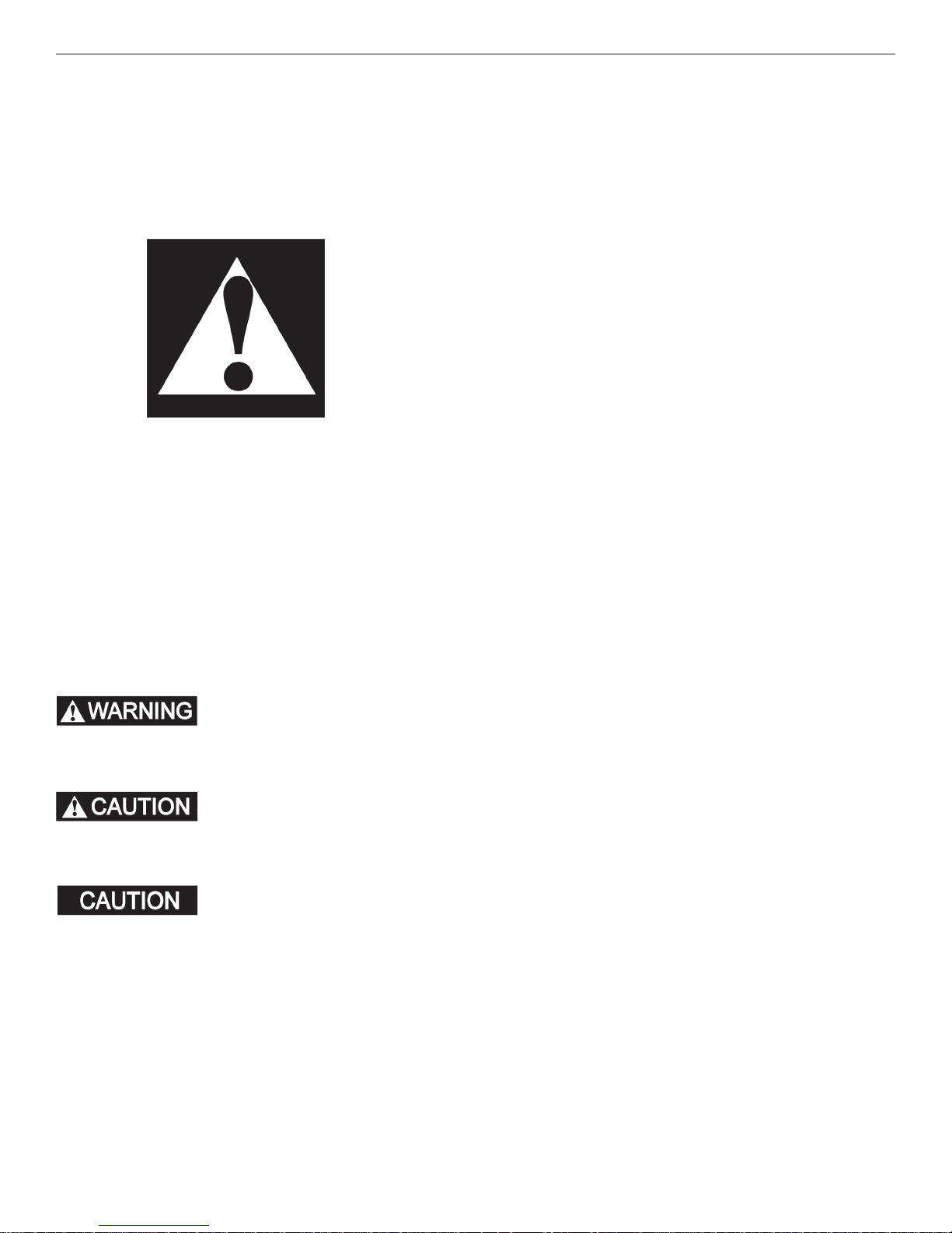
FIG. 1A: 8'-13' MODEL BRACKET SPACING
A
B
From End of
Back Rail
C
8' 10' 12' 13'
A 1" 1-1/2" 1-1/2" 1-1/2"
B 44" 53-1/4" 63-1/8" 73"
C 93-7/8" 112-1/2" 132-1/4" 151-7/8"
FIG. 1B: 15' MODEL BRACKET SPACING
C
A
From End of
Back Rail
B
B
15'
A 1-1/2"
B 55-1/8"
FIG. 1D
Behind Arm Attachment
8'-13' MODEL SHOWN
INSTALLATION INSTRUCTIONS
A. Installation Using Standard Brackets
1. Determine locations of mounting brackets on side
of vehicle. See FIG. 1A , FIG 1B, and FIG 1C.
2. The left and right brackets must be mounted behind where the arms are attached. (See FIG. 1D)
The outside edge of the bracket must be aligned
with, but not protruding beyond, the edge of back
of the aluminum case. See FIG. 1A for the 8'-13'
models. See FIG. 1B for the 15' models, and FIG.
1C for the 16' models, which use 4 brackets evenly
spaced.
3. Mark the wall bracket position. Using a bracket as
a template, mark the hole locations. Pre-drill holes
using a 5/16" drill bit (use 7/32" drill bit if drilling
through steel). Install top brackets with 1/4-20 X
2"L carriage bolts, nuts and washers provided.
C 171-1/2"
FIG. 1C: 16' MODEL BRACKET SPACING
B
B
A
From End of
Back Rail
16'
A 1-1/2"
B 57-3/4"
C 191-1/4"
To prevent water leakage, always use silicon
sealant where each fastener enters the vehicle
side wall or roof.
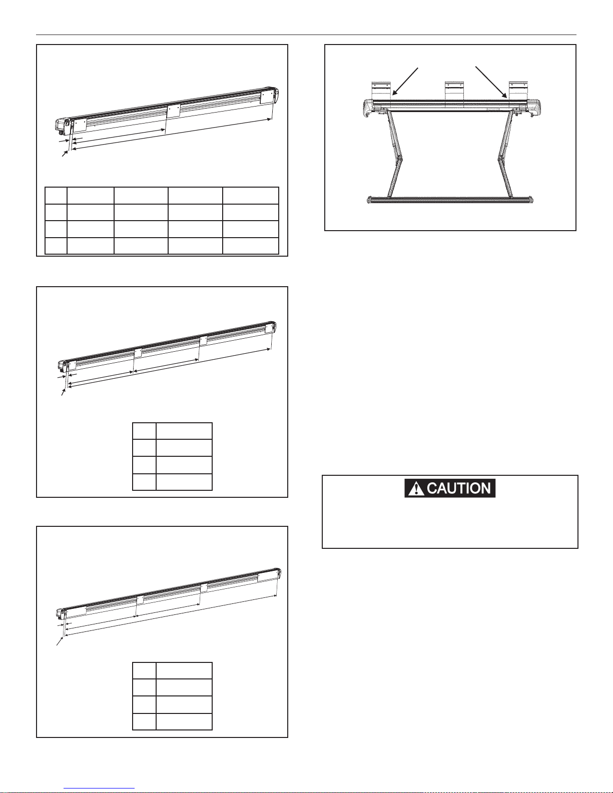
4. If mounting area sub-structure is not solid, we
recommend using a backing plate (not provided)
C
inside the vehicle. See FIG. 2.
5. After the wall brackets are installed, using a
pencil, mark location of edges of brackets on the
wall. Draw the marks approximately 2" below the
bracket. These marks will later help you identify
the location of the brackets for installation of the
8-18 X .38" self-drilling screws.
3
 Loading...