

Page 1
Dachentlüfter mit Motor
DE
ENFRESITNLDASV
NO
FI
PT
RU
PL
CSSKHU
GY11
Montage- und Bedienungsanleitung . 6
Roof vent with motor
Installation and Operating Manual. . 13
Ventilateur de toit à moteur
Instructions de montage
et de service . . . . . . . . . . . . . . . . . . 20
Extractor de techo con motor
Instrucciones de montaje y de uso . 28
Sfiatatoio a tetto con motore
Istruzioni di montaggio e d’uso . . . . 35
Dakventilator met motor
Montagehandleiding en
gebruiksaanwijzing . . . . . . . . . . . . . 43
Tagventilatoren med motor
Monterings- og
betjeningsvejledning . . . . . . . . . . . . 50
Takventilatorn med motor
Monterings- och bruksanvisning . . . 57
Takviften med motor
Monterings- og bruksanvisning . . . . 64
Moottoroitu kattotuuletin
Asennus- ja käyttöohje . . . . . . . . . . 71
Ventilador para tejadilho com
motor
Instruções de montagem e manual de
instruções . . . . . . . . . . . . . . . . . . . . 78
Накрышный вентилятор с
двигателем
Инструкция по монтажу и
эксплуатации. . . . . . . . . . . . . . . . . 86
Odpowietrznik dachowy z
silnikiem
Instrukcja montażu i obsługi . . . . . . 94
Střešní větrák s motorem
Návod k montáži a obsluze. . . . . . 102
Strešný vetrák s motorom
Návod na montáž a uvedenie do
prevádzky . . . . . . . . . . . . . . . . . . . 109
Tet ő szellőző motorral
Szerelési és használati útmutató . .116
Page 2

Page 3
1
2
105 mm
GY11
1
2
3
4
5
3
Page 4
GY11
3
1
2
3
4
5
4
Page 5
GY11
1
4
ws
sw
rt
2
3
1
5
5
Page 6

DE
Erklärung der Symbole GY11
Bitte lesen Sie diese Anleitung vor Einbau und Inbetriebnahme sorgfältig durch und bewahren Sie sie auf. Geben Sie sie im Falle einer
Weitergabe des Produktes an den Nutzer weiter.
Inhalt
1 Erklärung der Symbole . . . . . . . . . . . . . . . . . . . . . . . . . . . . . . . . . . . 6
2 Sicherheitshinweise . . . . . . . . . . . . . . . . . . . . . . . . . . . . . . . . . . . . . . 7
3 Lieferumfang . . . . . . . . . . . . . . . . . . . . . . . . . . . . . . . . . . . . . . . . . . . 8
4 Bestimmungsgemäßer Gebrauch . . . . . . . . . . . . . . . . . . . . . . . . . . . 9
5 Technische Beschreibung . . . . . . . . . . . . . . . . . . . . . . . . . . . . . . . . . 9
6 Dachentlüfter montieren. . . . . . . . . . . . . . . . . . . . . . . . . . . . . . . . . . . 9
7 Dachentlüfter verwenden . . . . . . . . . . . . . . . . . . . . . . . . . . . . . . . . . 11
8 Reinigung. . . . . . . . . . . . . . . . . . . . . . . . . . . . . . . . . . . . . . . . . . . . . 11
9 Entsorgung. . . . . . . . . . . . . . . . . . . . . . . . . . . . . . . . . . . . . . . . . . . . 12
10 Gewährleistung . . . . . . . . . . . . . . . . . . . . . . . . . . . . . . . . . . . . . . . . 12
11 Technische Daten . . . . . . . . . . . . . . . . . . . . . . . . . . . . . . . . . . . . . . 12
1 Erklärung der Symbole
WARNUNG!
!
!
A
6
Sicherheitshinweis: Nichtbeachtung kann zu Tod oder schwerer
Verletzung führen.
VORSICHT!
Sicherheitshinweis: Nichtbeachtung kann zu Verletzungen
führen.
ACHTUNG!
Nichtbeachtung kann zu Materialschäden führen und die
Funktion des Produktes beeinträchtigen.
Page 7

DE
GY11 Sicherheitshinweise
HINWEIS
I
➤ Handlung: Dieses Symbol zeigt Ihnen, dass Sie etwas tun müssen. Die
erforderlichen Handlungen werden Schritt für Schritt beschrieben.
✓ Dieses Symbol beschreibt das Ergebnis einer Handlung.
Abb. 1 5, Seite 3: Diese Angabe weist Sie auf ein Element in einer Abbildung hin, in diesem Beispiel auf „Position 5 in Abbildung 1 auf Seite 3“.
Ergänzende Informationen zur Bedienung des Produktes.
2 Sicherheitshinweise
Beachten Sie die vom Fahrzeughersteller und vom Kfz-Handwerk vorgeschriebenen Sicherheitshinweise und Auflagen!
Der Hersteller übernimmt in folgenden Fällen keine Haftung für Schäden:
Montage- oder Anschlussfehler
Beschädigungen am Produkt durch mechanische Einflüsse und Über-
spannungen
Veränderungen am Produkt ohne ausdrückliche Genehmigung vom
Hersteller
Verwendung für andere als die in der Anleitung beschriebenen Zwecke
Beachten Sie folgende grundsätzliche Sicherheitsmaßnahmen beim Gebrauch von elektrischen Geräten zum Schutz vor:
elektrischem Schlag
Brandgefahr
Verletzungen
2.1 Umgang mit dem Gerät
WARNUNG!
!
Die Montage und Reparaturen des Dachentlüfters dürfen nur
von qualifizierten Fachhandwerkern durchgeführt werden, die
mit den verbundenen Gefahren bzw. den gültigen Vorschriften
und Normen vertraut sind.
Durch unsachgemäße Reparaturen können erhebliche Gefah-
ren entstehen. Wenden Sie sich im Reparaturfall an den Service-Stützpunkt in Ihrem Land (Adressen auf der Rückseite).
7
Page 8

DE
Lieferumfang GY11
Personen (einschließlich Kinder), die aufgrund ihrer physi-
schen, sensorischen oder geistigen Fähigkeiten oder ihrer
Unerfahrenheit oder Unkenntnis nicht in der Lage sind, das
Produkt sicher zu benutzen, sollten dieses Produkt nicht ohne
Aufsicht oder Anweisung durch eine verantwortliche Person
nutzen.
Achten Sie beim Schneiden oder Bohren in Wand oder Decke
darauf, dass keine elektrischen Leitungen oder nicht sichtbare
Geräte beschädigt werden.
Der Abstand zwischen Gaskocherflamme und Dachentlüfter
muss mindestens 50 cm betragen.
Flambieren Sie niemals unter dem Dachentlüfter.
VORSICHT!
!
Der Dachentlüfter muss so sicher installiert werden, dass er
nicht herabfallen kann.
Betreiben Sie den Dachentlüfter nur, wenn das Gehäuse und
die Leitungen unbeschädigt sind.
Achten Sie darauf, dass keine brennbaren Gegenstände im Be-
reich des Luftaustritts gelagert bzw. montiert sind. Der Abstand
muss mindestens 50 cm betragen.
Greifen Sie nicht in den Lüftungsauslass und führen Sie keine
Gegenstände in das Gerät ein.
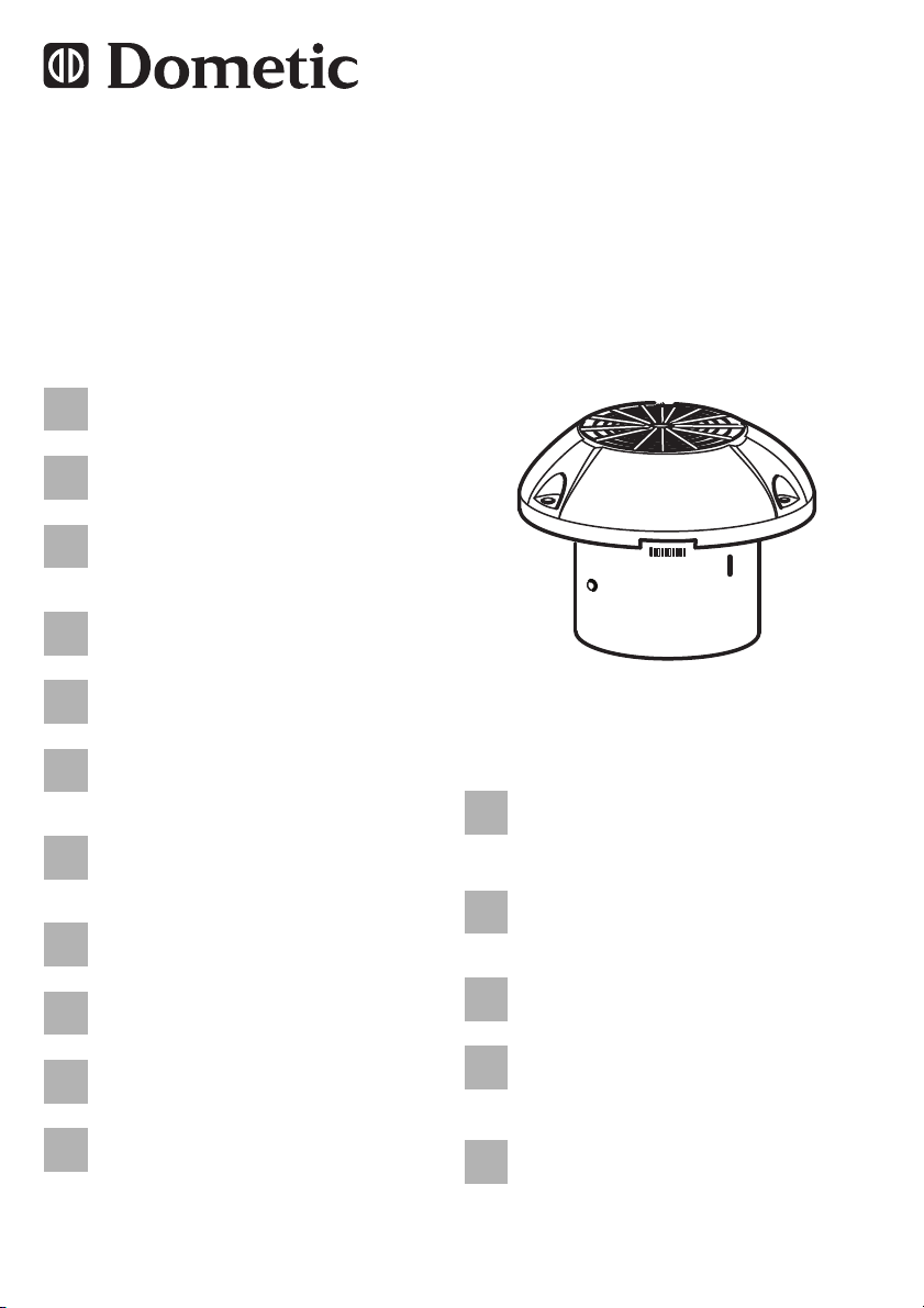
3Lieferumfang
Pos. in
Abb. 1,
Seite 3
1 1 Abdeckkappe
2 1 Dachhaube
3 1 Lüfter
4 1 Anschlusskabel mit Sicherung
5 1 Gummidichtung
8
Menge Beschreibung
Page 9

DE
GY11 Bestimmungsgemäßer Gebrauch
4 Bestimmungsgemäßer Gebrauch
Der Dachentlüfter mit Motor GY11 (grau, einteilig: Art.-Nr. 9107300318,
weiß, einteilig: Art.-Nr. 9107300307, weiß, 6-teilig: Art.-Nr. 9107300308) ist
für den Einbau in Wohnwagen, Wohnmobilen und Booten vorgesehen.
5 Technische Beschreibung
Der Dachentlüfter mit Motor GY11 dient der Entlüftung von Innenräumen in
Wohnwagen, Wohnmobilen und Booten. Er kann vorzugsweise in Toiletten,
Küchen, über Gas- und Petroleumlampen sowie in Duschräumen verwendet
werden. Die Abdeckkappe ist witterungsbeständig.
Der Lüfter wird durch einen Motor angetrieben. Die Flügel des Gebläserads
sind seitwärts gerichtet. So behindern sie bei stillstehendem Lüfter die Luftströmung nicht.
Der Lüfter wird durch einen Schalter mit drei Stellungen (Abb. 4 1, Seite 5)
gesteuert:
Stellung 1: Lüfterstufe 1, halbe Leistung (max. 65 m
Zwischenstellung: Lüfter ausgeschaltet
Stellung 2: Lüfterstufe 2, maximale Leistung (max. 105 m
3
/h)
3
/h)
6 Dachentlüfter montieren
Hinweise zur Montage
Der Dachentlüfter soll auf dem Dach auf möglichst ebener Fläche mon-
tiert werden. Bei Anbringen auf schrägem Untergrund muss die Dachhaube so gedreht werden, dass eine der drei Wasserablauföffnungen in
Richtung des Gefälles gerichtet ist. Ein Neigungswinkel bis zu 20° beeinträchtigt die Leistung des Lüfters bei stillstehendem Motor nicht.
Der Dachentlüfter zieht Luft aus dem Innenraum ab. Achten Sie auf eine
ausreichende Luftzufuhr! Die Öffnung für die Luftzufuhr muss eine Größe
von mindestens 60 cm
2
haben.
9
Page 10

DE
Dachentlüfter montieren GY11
Dachentlüfter montieren
➤ Wählen Sie auf dem Dach einen geeigneten Montageort für den Lüfter.
➤ Sehen Sie eine Öffnung für einen dreistufigen Schalter (nicht im Lieferum-
fang enthalten) vor, zum Beispiel an der Küchenzeile.
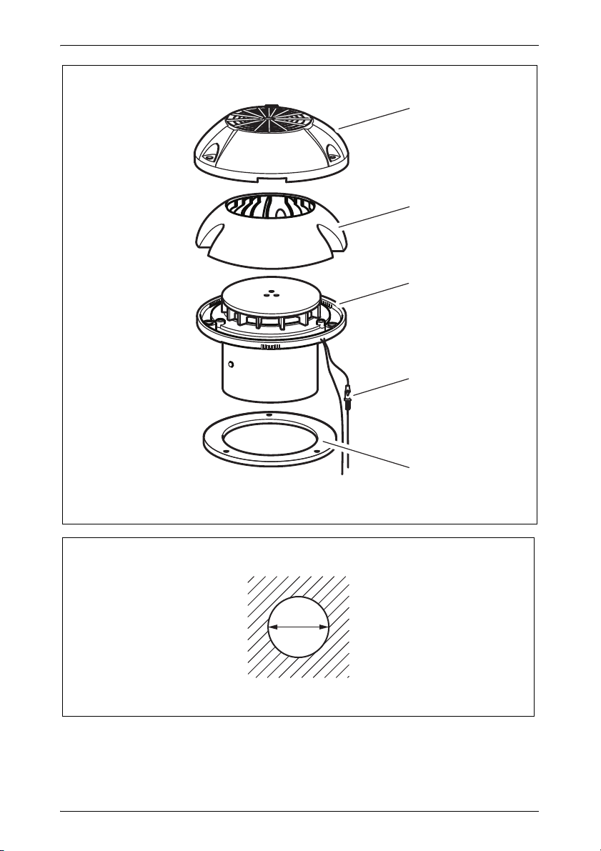
➤ Zeichnen Sie die Lage und Größe der Öffnung von 105 mm Durchmesser
für den Lüfter (Abb. 2, Seite 3) und eine Öffnung für den Schalter vor.
➤ Bohren Sie vor und schneiden Sie die Öffnungen auf dem Dach sorgfältig
mit einer Stichsäge o. ä. aus.
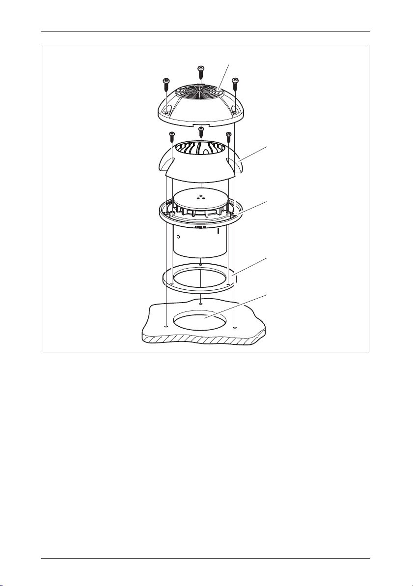
➤ Legen Sie den Lüfter (Abb. 3 3, Seite 4) auf die Öffnung (Abb. 3 5,
Seite 4) und markieren Sie die sechs Schraubenlöcher.
➤ Tragen Sie einen dünnen Ring aus einem dauerelastischen Abdichtungs-
material um jedes Loch auf.
➤ Setzen Sie die Gummidichtung (Abb. 3 4, Seite 4) in die Rille auf die
Unterseite des Lüfters ein.
➤ Befestigen Sie den Lüfter (Abb. 3 3, Seite 4) mit sechs Schrauben
(4,2 x 25).
HINWEIS
I
Ziehen Sie die Befestigungsschrauben des Lüfters so fest an,
dass die Gummidichtung nahtlos am Dach anliegt.
➤ Befestigen Sie die Dachhaube (Abb. 3 2, Seite 4) mit drei Schrauben
(3,5 x 9,5).
➤ Befestigen Sie die Abdeckkappe (Abb. 3 1, Seite 4) mit drei Schrauben
(4,2 x 13).
➤ Befestigen Sie den Schalter in der Nähe des Kochers.
10
Page 11
DE
GY11 Dachentlüfter verwenden
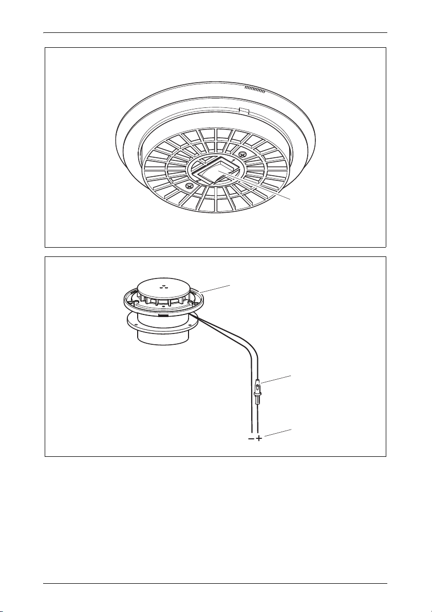
6.1 Dachentlüfter elektrisch anschließen
➤ Verbinden Sie den Lüfter mit der Batterie, siehe Abb. 5, Seite 5 .
Legende
Pos. in
Abb. 5,
Seite 5
Beschreibung
1Lüfter
2 Sicherungshalter mit Sicherung T4 A 5 x 20 mm
3 Batterie
sw schwarz
ws weiß
rt rot
7 Dachentlüfter verwenden
Dachentlüfter ein- und ausschalten
➤ Schalten Sie den Dachentlüfter mit dem Schalter (Abb. 4 1, Seite 5) ein
und aus.
Sie können zwischen 2 Leistungsstufen wählen:
– Stellung 1: Lüfterstufe 1 (halbe Leistung)
– Stellung 2: Lüfterstufe 2 (maximale Leistung)
8 Reinigung
ACHTUNG!
A
➤ Reinigen Sie das Produkt gelegentlich mit einem feuchten Tuch.
Keine scharfen oder harten Gegenstände oder Reinigungsmittel
zur Reinigung verwenden, da dies zu einer Beschädigung des
Produktes führen kann.
11
Page 12
DE
Entsorgung GY11
9 Entsorgung
➤ Geben Sie das Verpackungsmaterial möglichst in den entsprechenden
Recycling-Müll.
Wenn Sie das Produkt endgültig außer Betrieb nehmen, informieren Sie sich bitte beim nächsten Recyclingcenter oder bei
M
Ihrem Fachhändler über die zutreffenden Entsorgungsvorschriften.
10 Gewährleistung
Es gilt die gesetzliche Gewährleistungsfrist. Sollte das Produkt defekt sein,
wenden Sie sich bitte an die Niederlassung des Herstellers in Ihrem Land
(Adressen siehe Rückseite der Anleitung) oder an Ihren Fachhändler.
Zur Reparatur- bzw. Gewährleistungsbearbeitung müssen Sie folgende
Unterlagen mitschicken:
eine Kopie der Rechnung mit Kaufdatum,
einen Reklamationsgrund oder eine Fehlerbeschreibung.
11 Technische Daten
Dometic GY11
Artikelnummer: 9107300318
(grau, einteilig)
Anschlussspannung: 12 Vg
Entlüftungsleistung:
Leistungsaufnahme: 30 W
Abmessungen: 62 x 200 mm
Gewicht: 0,6 kg
Prüfzeichen:
Lüfterstufe 2: max. 105 m
(bei Windgeschwindigkeiten von 1 – 4 m/s)
9107300307
(weiß, einteilig)
Lüfterstufe 1: max. 65 m
ohne Lüfter: 3 – 12 m
12
9107300308
(weiß, 6-teilig)
3
/h
3
/h
3
/h
Page 13

EN
GY11 Explanation of symbols
Please read this instruction manual carefully before installation and
first use, and store it in a safe place. If you pass on the product to
another person, hand over this instruction manual along with it.
Contents
1 Explanation of symbols . . . . . . . . . . . . . . . . . . . . . . . . . . . . . . . . . . 13
2 Safety instructions . . . . . . . . . . . . . . . . . . . . . . . . . . . . . . . . . . . . . . 14
3 Scope of delivery . . . . . . . . . . . . . . . . . . . . . . . . . . . . . . . . . . . . . . . 15
4 Intended use . . . . . . . . . . . . . . . . . . . . . . . . . . . . . . . . . . . . . . . . . . 15
5 Technical description . . . . . . . . . . . . . . . . . . . . . . . . . . . . . . . . . . . . 16
6 Mounting the roof vent . . . . . . . . . . . . . . . . . . . . . . . . . . . . . . . . . . . 16
7 Using the roof vent. . . . . . . . . . . . . . . . . . . . . . . . . . . . . . . . . . . . . . 17
8 Cleaning. . . . . . . . . . . . . . . . . . . . . . . . . . . . . . . . . . . . . . . . . . . . . . 18
9 Disposal . . . . . . . . . . . . . . . . . . . . . . . . . . . . . . . . . . . . . . . . . . . . . . 18
10 Warranty . . . . . . . . . . . . . . . . . . . . . . . . . . . . . . . . . . . . . . . . . . . . . 18
11 Technical data . . . . . . . . . . . . . . . . . . . . . . . . . . . . . . . . . . . . . . . . . 19
1 Explanation of symbols
WARNING!
!
!
A
Safety instruction: Failure to observe this instruction can cause
fatal or serious injury.
CAUTION!
Safety instruction: Failure to observe this instruction can lead to
injury.
NOTICE!
Failure to observe this instruction can cause material damage and
impair the function of the product.
13
Page 14

EN
Safety instructions GY11
NOTE
I
➤ Action: This symbol indicates that action is required on your part. The
required action is described step-by-step.
✓ This symbol describes the result of an action.
Fig. 1 5, page 3: This refers to an element in an illustration. In this case,
item 5 in figure 1 on page 3.
Supplementary information for operating the product.
2 Safety instructions
Please observe the prescribed safety instructions and stipulations
from the vehicle manufacturer and service workshops.
The manufacturer accepts no liability for damage in the following cases:
Faulty assembly or connection
Damage to the product resulting from mechanical influences and excess
voltage
Alterations to the product without express permission from the manu-
facturer
Use for purposes other than those described in the operating manual
Note the following basic safety information when using electrical devices to
protect against:
Electric shock
Fire hazards
Injury
2.1 Handling the device
WARNING!
!
Installation and repair of the roof vent may only be carried out
by qualified personnel who are familiar with the risks involved
and the relevant regulations.
Inadequate repairs may cause serious hazards. For repair ser-
vice, please contact the service centre in your country (addresses on the back page).
14
Page 15

EN
GY11 Scope of delivery
People (including children) whose physical, sensory or mental
capacities or whose lack of experience or knowledge prevent
them from using this product safely should not use it without the
supervision or instruction of a responsible person.
When cutting or drilling into walls or ceilings, make sure that no
electrical cables or hidden devices are damaged.
The distance between the gas hob flame and the roof vent must
be at least 50 cm.
Never flambé food under the roof vent.
CAUTION!
!
The roof vent must be installed securely so that it cannot fall
down.
Only operate the roof vent if you are certain that the housing and
the cables are not damaged.
Make sure no combustible objects are stored or installed near
the air outlet. A distance of at least 50 cm must be maintained.
Do not reach into the air outlet or insert any foreign objects into
the device.
3 Scope of delivery
No. in
fig. 1,
page 3
1 1 Cover cap
2 1 Roof hood
3 1 Vent
4 1 Connection cable with fuse
5 1 Rubber seal
Quantity Description
4 Intended use
The roof vent with motor GY11 (grey, one part: item no. 9107300318, white,
one part: item no. 9107300307, white, six parts: item no. 9107300308) is designed for installation in caravans, motorhomes and boats.
15
Page 16

EN
Technical description GY11
5 Technical description
The roof vent with motor GY11 is for ventilating the interiors of caravans, motorhomes and boats. It can also be used in toilets, kitchens, above gas and
paraffin lamps and in shower rooms. The cover cap is weatherproof.
The vent is motorised. The blades of the vent wheel are directed towards the
side. They therefore do not obstruct the air flow when the vent is off.
The vent is controlled by a switch with three settings (fig. 4 1, page 5):
Setting 1: Fan speed 1, half power (max. 65 m
Intermediate setting: Fan switched off
Setting 2: Fan speed 2, maximum power (max. 105 m
3
/h)
3
/h)
6 Mounting the roof vent
Note on installation location
The vent should be mounted on the roof on a level surface. When mount-
ed on a sloping surface, the roof hood must be rotated so that one of the
three water drainage holes is directed toward the incline. A tilt angle up to
20° will not affect the performance of the vent when the motor is not running.
The vent removes air from the interior. Make sure there is an adequate air
supply! The air intake opening must be at least 60 cm
2
.
Mounting the vent
➤ Select an appropriate installation location for the vent on the roof.
➤ Provide an opening for a three-step switch (not included in scope of deliv-
ery), for example at the kitchen unit.
➤ Draw the location and size of the opening of 105 mm diameter for the vent
(fig. 2, page 3) and for the opening of the switch.
➤ Pre-drill and cut out the holes on the roof carefully with a keyhole saw or
similar tool.
➤ Place the vent (fig. 3 3, page 4) on the opening (fig. 3 5, page 4) and
mark the six screw holes.
➤ Apply a thin ring of a permanently elastic sealing material around each
hole.
16
Page 17
EN
GY11 Using the roof vent
➤ Put the rubber seal (fig. 3 4, page 4) into the groove on the underside of
the vent.
➤ Attach the vent (fig. 3 3, page 4) with six bolts (4,2 x 25).
NOTE
I
➤ Attach the roof hood (fig. 3 2, page 4) with three bolts (3,5 x 9,5).
➤ Attach the cover cap (fig. 3 1, page 4) with three bolts (4,2 x 13).
➤ Attach the switch next to the stove.
Pull the vent on tightly enough that the rubber seal is seamlessly
in contact with the roof.
6.1 Connecting the roof vent electrically
➤ Connect the vent to the battery; see fig. 5, page 5.
Key
No. in
fig. 5,
page 5
Description
1 Vent
2 Fuse holder with fuse T4 A 5 x 20 mm
3 Battery
sw Black
ws White
rt Red
7 Using the roof vent
Switching the vent on and off
➤ Turn the vent on and off with the switch (fig. 4 1, page 5).
You can choose between two speeds:
– Setting 1: Fan speed 1 (half power)
– Setting 2: Fan speed 2 (maximum power)
17
Page 18

EN
Cleaning GY11
8 Cleaning
NOTICE!
A
➤ Occasionally clean the product with a damp cloth.
Do not use sharp or hard objects or cleaning agents for cleaning
as these may damage the product.
9 Disposal
➤ Place the packaging material in the appropriate recycling waste bins
wherever possible.
If you wish to finally dispose of the product, ask your local recycling
centre or specialist dealer for details about how to do this in
M
accordance with the applicable disposal regulations.
10 Warranty
The statutory warranty period applies. If the product is defective, please
contact the manufacturer's branch in your country (see the back of the
instruction manual for the addresses) or your retailer.
For repair and guarantee processing, please include the following documents when you send in the device:
A copy of the receipt with purchasing date
A reason for the claim or description of the fault
18
Page 19
EN
GY11 Technical data
11 Technical data
Dometic GY11
Item number: 9107300318
(grey, one part)
Connection voltage:
Capacity:
Without fan: 3 – 12 m
Power consumption:
Dimensions
(WxHxD):
Weight: 0.6 kg
Test mark:
Fan speed 2: max. 105 m
9107300307
(white, one part)
12 Vg
Fan speed 1: max. 65 m
3
/h (at wind speeds of 1 – 4 m/s)
30 W
62 x 200 mm
9107300308
(white, six parts)
3
/h
3
/h
19
Page 20

FR
Explication des symboles GY11
Veuillez lire attentivement cette notice avant le montage et la mise en
service. Veuillez ensuite la conserver. En cas de passer le produit,
veuillez le transmettre au nouvel acquéreur.
Sommaire
1 Explication des symboles. . . . . . . . . . . . . . . . . . . . . . . . . . . . . . . . . 20
2 Consignes de sécurité . . . . . . . . . . . . . . . . . . . . . . . . . . . . . . . . . . . 21
3 Contenu de la livraison . . . . . . . . . . . . . . . . . . . . . . . . . . . . . . . . . . 22
4 Usage conforme. . . . . . . . . . . . . . . . . . . . . . . . . . . . . . . . . . . . . . . . 23
5 Description technique . . . . . . . . . . . . . . . . . . . . . . . . . . . . . . . . . . . 23
6 Montage du ventilateur de toit . . . . . . . . . . . . . . . . . . . . . . . . . . . . . 23
7 Utilisation du ventilateur de toit . . . . . . . . . . . . . . . . . . . . . . . . . . . . 25
8 Nettoyage. . . . . . . . . . . . . . . . . . . . . . . . . . . . . . . . . . . . . . . . . . . . . 25
9 Élimination . . . . . . . . . . . . . . . . . . . . . . . . . . . . . . . . . . . . . . . . . . . . 26
10 Garantie . . . . . . . . . . . . . . . . . . . . . . . . . . . . . . . . . . . . . . . . . . . . . . 26
11 Caractéristiques techniques. . . . . . . . . . . . . . . . . . . . . . . . . . . . . . . 27
1 Explication des symboles
AVERTISSEMENT !
!
!
A
20
Consigne de sécurité : le non-respect de ces consignes peut
entraîner la mort ou de graves blessures.
ATTENTION !
Consigne de sécurité : le non-respect de ces consignes peut
entraîner des blessures.
AVIS !
Le non-respect de ces consignes peut entraîner des dommages
matériels et des dysfonctionnements du produit.
Page 21

FR
GY11 Consignes de sécurité
REMARQUE
I
➤ Manipulation : ce symbole vous indique une action à effectuer. Les
manipulations à effectuer sont décrites étape par étape.
✓ Ce symbole décrit le résultat d’une manipulation.
Fig. 1 5, page 3 : cette information renvoie à un élément figurant sur une
illustration, dans cet exemple à la « position 5 de l'illustration 1 à la page 3 ».
Informations complémentaires sur l'utilisation du produit.
2 Consignes de sécurité
Respectez les consignes de sécurité et autres prescriptions imposées
par le fabricant du véhicule et par les professionnels de l’automobile !
Le fabricant décline toute responsabilité pour des dommages dans les cas
suivants :
des défauts de montage ou de raccordement
des influences mécaniques et des surtensions ayant endommagé le
matériel
des modifications apportées au produit sans autorisation explicite de la
part du fabricant
une utilisation différente de celle décrite dans la notice
Lors de l’utilisation d’appareils électriques, les consignes générales de sécurité suivantes doivent être respectées afin d’éviter
une décharge électrique,
un incendie,
des blessures.
2.1 Précautions d'usage
AVERTISSEMENT !
!
Le montage et les réparations du ventilateur de toit doivent être
effectués par des artisans qualifiés et parfaitement informés des
dangers correspondants et des directives et normes en vigueur.
21
Page 22
FR
Contenu de la livraison GY11
Toute réparation mal effectuée risquerait d'entraîner de graves
dangers. Si des réparations sont nécessaires, adressez-vous à
la filiale chargée du service après-vente dans votre pays
(adresses au dos de la notice).
Ne laissez pas des personnes (enfants compris) incapables
d'utiliser le produit de manière sûre, en raison de déficiences
physiques, sensorielles ou mentales ou de leur manque d'expérience ou de connaissances, utiliser ce produit sans surveillance.
Lors de la découpe ou du perçage dans les murs ou les pla-
fonds, veillez à ce qu'aucune conduite électrique ou appareil
non visible ne soit endommagé.
La distance entre la flamme d'un réchaud à gaz et le ventilateur
de toit doit être d'au moins 50 cm.
Ne faites jamais rien flamber sous le ventilateur de toit.
ATTENTION !
!
Le ventilateur de toit doit être installé de manière à ce qu'il ne
puisse pas tomber !
Faites fonctionner le ventilateur de toit uniquement si le boîtier
et les conduites sont intacts.
Veillez à ce qu'aucun objet inflammable ne soit entreposé ni
monté dans la zone de sortie de l'air. Il convient de maintenir
une distance de 50 cm minimum.
Ne glissez pas les doigts dans la sortie d'air et n'introduisez au-
cun objet à l'intérieur de l'appareil.
3 Contenu de la livraison
Pos. dans
fig. 1, page 3
1 1 Cache
2 1 Lanterneau
3 1 Ventilateur
4 1 Câble de raccordement avec fusible
5 1 Joint en caoutchouc
22
Quantité Description
Page 23

FR
GY11 Usage conforme
4 Usage conforme
Le ventilateur de toit à moteur GY11 (gris, une pièce : n° d’article
9107300318, blanc, une pièce : n° d’article 9107300307, blanc, six pièces :
n° d’article 9107300308) est conçu pour le montage dans des caravanes,
campings-cars et bateaux.
5 Description technique
Le ventilateur de toit à moteur GY11 sert à ventiler l'intérieur des caravanes,
campings-cars et bateaux. Il peut être utilisé de préférence dans les toilettes,
cuisines, au-dessus des lampes à gaz et à pétrole ainsi que dans les salles
de douche. Le capot résiste aux intempéries.
Le ventilateur est entraîné par un moteur. Les ailettes de la roue sont dirigées
vers le côté. Elles n'empêchent ainsi pas l'écoulement de l'air lorsque le ventilateur est arrêté.
Le ventilateur est commandé par un commutateur à trois positions (fig. 4 1,
page 5) :
Position 1 : vitesse de ventilation 1, mi-puissance (max. 65 m
Position intermédiaire : ventilateur éteint
Position 2 : vitesse de ventilation 2, puissance maximale (max. 105 m
3
/h)
3
/h)
6 Montage du ventilateur de toit
Consignes de sécurité concernant le montage
Le ventilateur de toit se monte sur le toit, sur une surface aussi plane que
possible. En cas de montage sur une surface inclinée, le dôme doit être
tourné de telle sorte que l'une des trois ouvertures d'écoulement de l'eau
soit orientée dans le sens de la pente. Un angle d'inclinaison allant jusqu'à 20° ne nuit pas à la performance du ventilateur lorsque le moteur est
arrêté.
Le ventilateur de toit évacue l'air de l'intérieur. Veillez à ce que l'arrivée
d'air soit suffisante ! La taille de l'ouverture pour l'arrivée d'air doit être
d'au moins 60 cm
2
.
23
Page 24

FR
Montage du ventilateur de toit GY11
Montage du ventilateur de toit
➤ Choisissez un emplacement de montage adapté sur le toit pour le venti-
lateur.
➤ Prévoyez une ouverture pour un commutateur à trois positions (non com-
pris dans la livraison), par exemple dans la cuisine.
➤ Dessinez l'emplacement et la taille de l'ouverture de 105 mm de diamètre
pour le ventilateur (fig. 2, page 3) et une ouverture pour le commutateur.
➤ Percez et découpez soigneusement les ouvertures sur le toit avec une
scie sauteuse ou un outil similaire.
➤ Placez le ventilateur (fig. 3 3, page 4) sur l'ouverture (fig. 3 5, page 4)
et marquez les six trous des vis.
➤ Positionnez un anneau fin en matériau d'étanchéité à élasticité durable
autour de chaque trou.
➤ Placez le joint en caoutchouc (fig. 3 4, page 4) dans la rainure sur la
face inférieure du ventilateur.
➤ Fixez le ventilateur (fig. 3 3, page 4) avec six vis (4,2 x 25).
REMARQUE
I
Vissez les vis de fixation du ventilateur de sorte que le joint en
caoutchouc soit parfaitement appliqué contre le toit.
➤ Fixez le dôme (fig. 3 2, page 4) avec trois vis (3,5 x 9,5).
➤ Fixez le capot (fig. 3 1, page 4) avec trois vis (4,2 x 13).
➤ Fixez le commutateur à proximité du réchaud.
24
Page 25
FR
GY11 Utilisation du ventilateur de toit
6.1 Raccordement électrique du ventilateur de toit
➤ Raccordez le ventilateur à la batterie, voir fig. 5, page 5.
Légende
Pos. dans
fig. 5, page 5
1 Ventilateur
2 Porte-fusible avec fusible T4 A 5 x 20 mm
3 Batterie
sw noir
ws blanc
rt rouge
Description
7 Utilisation du ventilateur de toit
Mise en marche / à l'arrêt du ventilateur de toit
➤ Mettez en marche et arrêtez le ventilateur de toit à l'aide du commutateur
(fig. 4 1, page 5).
Vous avez le choix entre 2 vitesses :
– Position 1 : vitesse de ventilation 1 (mi-puissance)
– Position 2 : vitesse de ventilation 2 (puissance maximale)
8 Nettoyage
AVIS !
A
➤ Nettoyez le produit avec un tissu humide.
N’utilisez aucun objet coupant ou dur, ni de détergents pour le
nettoyage. Cela pourrait endommager le produit.
25
Page 26

FR
Élimination GY11
9 Élimination
➤ Jetez les emballages dans les conteneurs de déchets recyclables prévus
à cet effet.
Lorsque vous mettrez votre produit définitivement hors service,
informez-vous auprès du centre de recyclage le plus proche ou
M
auprès de votre revendeur spécialisé sur les prescriptions relatives
au retraitement des déchets.
10 Garantie
Le délai légal de garantie s'applique. Si le produit s'avérait défectueux,
veuillez vous adresser à la filiale du fabricant située dans votre pays (voir
adresses au verso du présent manuel) ou à votre revendeur spécialisé.
Veuillez y joindre les documents suivants pour la gestion des réparations et
de la garantie :
une copie de la facture avec la date d'achat,
le motif de la réclamation ou une description du dysfonctionnement.
26
Page 27

FR
GY11 Caractéristiques techniques
11 Caractéristiques techniques
Dometic GY11
Numéro de
l'article :
Tension de raccordement :
Puissance de
ventilation :
Puissance
absorbée :
Dimensions : 62 x 200 mm
Poids : 0,6 kg
Conformité :
9107300318
(gris, une pièce)
vitesse de ventilation 2 : max. 105 m
vitesse de ventilation 1 : max. 65 m
(pour une vitesse de vent de 1à4m/s)
9107300307
(blanc, une pièce)
12 Vg
sans ventilateur : 3 – 12 m
30 W
9107300308
(blanc, 6 pièces)
3
/h
3
/h
3
/h
27
Page 28

ES
Explicación de los símbolos GY11
Lea detenidamente estas instrucciones antes de llevar a cabo la instalación y puesta en funcionamiento, y consérvelas en un lugar seguro.
En caso de vender o entregar el producto a otra persona, entregue
también estas instrucciones.
Índice
1 Explicación de los símbolos. . . . . . . . . . . . . . . . . . . . . . . . . . . . . . . 28
2 Indicaciones de seguridad . . . . . . . . . . . . . . . . . . . . . . . . . . . . . . . . 29
3 Volumen de entrega. . . . . . . . . . . . . . . . . . . . . . . . . . . . . . . . . . . . . 30
4 Uso adecuado . . . . . . . . . . . . . . . . . . . . . . . . . . . . . . . . . . . . . . . . . 31
5 Descripción técnica . . . . . . . . . . . . . . . . . . . . . . . . . . . . . . . . . . . . . 31
6 Montaje del extractor de techo. . . . . . . . . . . . . . . . . . . . . . . . . . . . . 31
7 Empleo del extractor de techo . . . . . . . . . . . . . . . . . . . . . . . . . . . . . 33
8 Limpieza. . . . . . . . . . . . . . . . . . . . . . . . . . . . . . . . . . . . . . . . . . . . . . 33
9 Gestión de residuos . . . . . . . . . . . . . . . . . . . . . . . . . . . . . . . . . . . . . 34
10 Garantía legal . . . . . . . . . . . . . . . . . . . . . . . . . . . . . . . . . . . . . . . . . 34
11 Datos técnicos . . . . . . . . . . . . . . . . . . . . . . . . . . . . . . . . . . . . . . . . . 34
1 Explicación de los símbolos
¡ADVERTENCIA!
!
!
A
28
Indicación de seguridad: su incumplimiento puede acarrear la
muerte o graves lesiones.
¡ATENCIÓN!
Indicación de seguridad: su incumplimiento puede acarrear
lesiones.
¡AVISO!
Su incumplimiento puede acarrear daños materiales y perjudicar
el correcto funcionamiento del producto.
Page 29

ES
GY11 Indicaciones de seguridad
NOTA
I
➤ Paso a seguir: este símbolo le indica que debe realizar un paso. Todos
los procedimientos necesarios se describen paso a paso.
✓ Este símbolo describe el resultado de un paso realizado.
Fig. 1 5, página 3: esta indicación hace referencia a un elemento de una
figura, en este ejemplo a la “Posición 5 en la figura 1 de la página 3”.
Información adicional para el manejo del producto.
2 Indicaciones de seguridad
Tenga en cuenta las indicaciones de seguridad y la documentación suministrada por el fabricante y el taller del vehículo.
El fabricante declina toda responsabilidad ante daños ocurridos en los
siguientes casos:
errores de montaje o de conexión,
daños en el producto debido a influencias mecánicas y sobretensiones
modificaciones realizadas en el producto sin el expreso consentimiento
del fabricante
utilización del aparato para fines distintos a los descritos en las instruc-
ciones.
Al utilizar los aparatos eléctricos, respete las siguientes normas básicas de
seguridad para protegerse de:
descargas eléctricas
peligro de incendio
lesiones
2.1 Manejo del aparato
¡ADVERTENCIA!
!
Solo personal técnico que conozca los posibles peligros y las
normas correspondientes tiene autorización para realizar las tareas de instalación y la reparación del extractor de techo.
29
Page 30

ES
Volumen de entrega GY11
Las reparaciones que se realicen incorrectamente pueden dar
lugar a situaciones de considerable peligro. En caso de reparaciones, diríjase al punto de atención al cliente de su país (direcciones al dorso).
Las personas (incluidos los niños) que, debido a sus capacida-
des físicas, sensoriales o mentales, a su falta de experiencia o
a desconocimiento, no pueden utilizar el producto de forma segura, no tienen permitido utilizar este producto sin la vigilancia
y las instrucciones de una persona sobre la que recae tal responsabilidad.
Cuando taladre o perfore la pared o el techo, preste atención a
no dañar ningún cable eléctrico o aparatos no visibles.
La distancia entre la llama del hornillo de gas y el extractor de
techo debe ser como mínimo de 50 cm.
No flamee nunca debajo del extractor de techo.
¡ATENCIÓN!
!
Instale el extractor de techo de forma segura para evitar que se
pueda caer.
Utilice el extractor de techo solo cuando la carcasa y los cables
no presenten daños.
Asegúrese de que no haya ningún objeto inflamable situado o
instalado en el área de salida de aire. La distancia debe ser
como mínimo de 50 cm.
No introduzca las manos en las salidas de ventilación ni inserte
objetos extraños en el aparato.
3 Volumen de entrega
Pos. en fig. 1,
página 3
11Tapa
2 1 Claraboya
31Extractor
4 1 Cable de conexión con fusible
5 1 Junta de goma
30
Cantidad Descripción
Page 31

ES
GY11 Uso adecuado
4 Uso adecuado
El extractor de techo con motor GY11 (gris, una pieza: n.° art. 9107300318;
blanco, una pieza: n.° art. 9107300307; blanco, 6 piezas: n.° art.
9107300308) está previsto para ser integrado en autocaravanas, caravanas
y embarcaciones.
5 Descripción técnica
El extractor de techo con motor GY11 sirve para ventilar habitáculos de autocaravanas, caravanas y embarcaciones. Puede utilizarse de preferencia
en aseos, cocinas, sobre lamparas de gas o de petróleo y en duchas. La tapa
es resistente a la intemperie.
El extractor es accionado por un motor. Las aspas de la rueda del extractor
están orientadas hacia un lado. Así no queda obstaculizada la corriente de
aire cuando el extractor esté parado.
El funcionamiento del extractor queda controlado por un interruptor con tres
posiciones (fig. 4 1, página 5):
Posición 1: Nivel de extractor 1, media potencia (máx. 65 m
Posición intermedia: Extractor apagado
Posición 2: Nivel de extractor 2, máxima potencia (máx. 105 m
3
/h)
3
/h)
6 Montaje del extractor de techo
Indicaciones para el montaje
El extractor de techo debe montarse en el techo sobre una superficie lo
más plana posible. Si se instala sobre una base inclinada, la claraboya
debe girarse de modo que uno de los tres orificios de salida de agua esté
orientado hacia el declive. Un ángulo de inclinación de hasta 20° no afecta a la potencia del extractor con el motor parado.
El extractor de techo extrae aire del habitáculo. ¡Asegúrese de que haya
una entrada de aire suficiente! La abertura para el extractor de techo
debe tener un diámetro de al menos 60 cm
2
.
31
Page 32

ES
Montaje del extractor de techo GY11
Montaje del extractor de techo
➤ Elija en el techo un lugar de montaje adecuado para el extractor.
➤ Debe disponer de una abertura para un interruptor de tres etapas (no in-
cluido en el volumen de entrega), por ejemplo, en la cocina.
➤ Dibuje la posición y el tamaño de la abertura de 105 mm de diámetro para
el extractor (fig. 2, página 3) y la abertura para el interruptor.
➤ Taladre previamente y recorte cuidadosamente las aberturas en el techo
con una sierra de calar o una herramienta similar.
➤ Coloque el extractor (fig. 3 3, página 4) en la abertura (fig. 3 5,
página 4) y marque los seis orificios de tornillos.
➤ Aplique sobre cada orificio un círculo fino de un material de sellado de
elasticidad permanente.
➤ Coloque la junta de goma (fig. 3 4, página 4) en la ranura situada en la
parte inferior del extractor.
➤ Fije el extractor (fig. 3 3, página 4) con seis tornillos (4,2 x 25).
NOTA
I
Apriete los tornillos de fijación del extractor hasta que la junta de
goma quede completamente pegada al techo.
➤ Fije la claraboya (fig. 3 2, página 4) con tres tornillos (3,5 x 9,5).
➤ Fije la tapa (fig. 3 1, página 4) con tres tornillos (4,2 x 13).
➤ Fije el interruptor cerca del hornillo.
32
Page 33

ES
GY11 Empleo del extractor de techo
6.1 Conexión eléctrica del extractor de techo
➤ Conecte el extractor a la batería; véase fig. 5, página 5.
Leyenda
Pos. en fig. 5,
página 5
1Extractor
2 Portafusibles con fusible T4 A 5 x 20 mm
3 Batería
sw negro
ws blanco
rt rojo
Descripción
7 Empleo del extractor de techo
Encender y apagar el extractor de techo
➤ Encienda y apague el extractor de techo con el interruptor (fig. 4 1,
página 5).
Puede elegir entre 2 niveles de potencia:
– Posición 1: Nivel de extractor 1 (media potencia)
– Posición 2: Nivel de extractor 2 (máxima potencia)
8Limpieza
¡AVISO!
A
➤ Limpie de vez en cuando el producto con un paño húmedo.
No utilice ningún objeto o producto de limpieza corrosivo o duro
en la limpieza, ya que podría dañar el producto.
33
Page 34

ES
Gestión de residuos GY11
9 Gestión de residuos
➤ Deseche el material de embalaje en el contenedor de reciclaje correspon-
diente.
Cuando vaya a desechar definitivamente el producto, infórmese en
el centro de reciclaje más cercano o en un comercio especializado
M
sobre las normas pertinentes de eliminación de materiales.
10 Garantía legal
Rige el plazo de garantía legal. Si el producto presenta algún defecto,
diríjase a la sucursal del fabricante de su país (ver direcciones en el dorso
de estas instrucciones) o a su establecimiento especializado.
Para la tramitación de la reparación y de la garantía debe enviar también los
siguientes documentos:
una copia de la factura con fecha de compra,
el motivo de la reclamación o una descripción de la avería.
11 Datos técnicos
Dometic GY11
Número de artículo: 9107300318
(gris, una pieza)
Tensión de conexión: 12 Vg
Potencia de extracción:
Consumo de potencia: 30 W
Dimensiones: 62 x 200 mm
Peso: 0,6 kg
Marca de homologación:
Nivel de extractor 2, máx. 105 m
Nivel de extractor 1, máx. 65 m
(con una velocidad del viento de 1–4m/s)
9107300307
(blanco, una pieza)
Sin extractor: 3 – 12 m
34
9107300308
(blanco, 6 piezas)
3
/h
3
/h
3
/h
Page 35

IT
GY11 Spiegazione dei simboli
Prima di effettuare il montaggio e la messa in funzione leggere
accuratamente questo manuale di istruzioni, conservarlo e in caso di
trasmissione del prodotto, consegnarlo all'utente successivo.
Indice
1 Spiegazione dei simboli . . . . . . . . . . . . . . . . . . . . . . . . . . . . . . . . . . 35
2 Indicazioni di sicurezza . . . . . . . . . . . . . . . . . . . . . . . . . . . . . . . . . . 36
3 Dotazione. . . . . . . . . . . . . . . . . . . . . . . . . . . . . . . . . . . . . . . . . . . . . 37
4 Uso conforme alla destinazione. . . . . . . . . . . . . . . . . . . . . . . . . . . . 38
5 Descrizione tecnica . . . . . . . . . . . . . . . . . . . . . . . . . . . . . . . . . . . . . 38
6 Montaggio dello sfiatatoio a tetto . . . . . . . . . . . . . . . . . . . . . . . . . . . 38
7 Impiego dello sfiatatoio a tetto . . . . . . . . . . . . . . . . . . . . . . . . . . . . . 40
8 Pulizia . . . . . . . . . . . . . . . . . . . . . . . . . . . . . . . . . . . . . . . . . . . . . . . 40
9 Smaltimento . . . . . . . . . . . . . . . . . . . . . . . . . . . . . . . . . . . . . . . . . . . 41
10 Garanzia . . . . . . . . . . . . . . . . . . . . . . . . . . . . . . . . . . . . . . . . . . . . . 41
11 Specifiche tecniche . . . . . . . . . . . . . . . . . . . . . . . . . . . . . . . . . . . . . 42
1 Spiegazione dei simboli
AVVERTENZA!
!
!
A
Avviso di sicurezza: la mancata osservanza di questo avviso
può causare ferite gravi anche mortali.
ATTENZIONE!
Avviso di sicurezza: la mancata osservanza di questo avviso
può essere causa di lesioni.
AVVISO!
La mancata osservanza di questa nota può causare danni materiali e compromettere il funzionamento del prodotto.
35
Page 36

IT
Indicazioni di sicurezza GY11
NOTA
I
➤ Modalità di intervento: questo simbolo indica all'utente che è necessario
un intervento. Le modalità di intervento necessarie saranno descritte
passo dopo passo.
✓ Questo simbolo descrive il risultato di un intervento.
Fig. 1 5, pagina 3: questi dati si riferiscono ad un elemento in una figura,
in questo caso alla “posizione 5 nella figura 1 a pagina 3”.
Informazioni integranti relative all'impiego del prodotto.
2 Indicazioni di sicurezza
Osservare le istruzioni per la sicurezza e le direttive previste dal produttore del veicolo e degli specialisti del settore!
Il produttore non si assume nessuna responsabilità per danni nei seguenti
casi:
errori di montaggio o di allacciamento
danni al prodotto dovuti a influenze meccaniche o a sovratensioni
modifiche al prodotto senza esplicita autorizzazione del produttore
impiego per altri fini rispetto a quelli descritti nel manuale di istruzioni
Durante l'uso di apparecchi elettrici attenersi alle misure di sicurezza fondamentali descritte qui in seguito per proteggersi da:
scosse elettriche
pericolo di incendio
lesioni
2.1 Utilizzo dell'apparecchio
AVVERTENZA!
!
I lavori di montaggio e riparazione dello sfiatatoio a tetto devono
essere effettuati solo da personale specializzato, informato sui
pericoli connessi e sulle relative prescrizioni e norme vigenti.
Le riparazioni effettuate in modo scorretto possono causare ri-
schi enormi. In caso di riparazioni, rivolgersi al Centro di assistenza del proprio Paese (l’indirizzo si trova sul retro di questo
manuale).
36
Page 37

IT
GY11 Dotazione
Le persone (bambini compresi) che, a causa delle proprie capa-
cità fisiche, sensoriali o mentali o della propria inesperienza e
scarsa conoscenza, non sono in grado di utilizzare il prodotto in
modo sicuro, devono evitare di utilizzare l'apparecchio se non in
presenza di terzi e seguendo le istruzioni di una persona per
loro responsabile.
Fare attenzione, in fase di taglio o di perforazione in una parete
o nel soffitto, a non danneggiare alcun cavo elettrico o dispositivi non direttamente visibili.
La distanza tra la fiamma di un fornello a gas e lo sfiatatoio a
tetto deve essere come minimo di 50 cm.
Non cucinare mai alla fiamma sotto lo sfiatatoio a tetto.
ATTENZIONE!
!
Installare lo sfiatatoio a tetto in modo tale che non possa cade-
re.
Utilizzare lo sfiatatoio a tetto solamente se l'alloggiamento e i
cavi non sono danneggiati.
Assicurarsi che nella zona di fuoriuscita dell'aria non siano col-
locati o montati oggetti infiammabili. La distanza minima deve
essere 50 cm.
Non intervenire nell'area della bocchetta di aerazione e non in-
trodurre alcun oggetto nel dispositivo.
3Dotazione
Pos. in fig. 1,
pagina 3
1 1 Cappuccio di protezione
2 1 Copertura
31Sfiatatoio
4 1 Cavo di collegamento con accoppiamento Schuko
5 1 Guarnizione in gomma
Quantità Descrizione
37
Page 38

IT
Uso conforme alla destinazione GY11
4 Uso conforme alla destinazione
Lo sfiatatoio a tetto con motore GY11 (grigio, monoblocco: num. art.
9107300318, bianco, monoblocco: num. art. 9107300307, bianco, in 6 parti:
num. art. 9107300308) è adatto per l'installazione su camper, roulotte e
barche.
5 Descrizione tecnica
Lo sfiatatoio a tetto con motore GY11 serve all'areazione di spazi interni di
camper, roulotte e imbarcazioni. Il dispositivo può essere utilizzato preferibilmente in toilette, cucine, in punti al di sopra di lampade a gas e petrolio, nonché in locali docce. La copertura è resistente alle intemperie.
Lo sfiatatoio è azionato da un motore. Le alette della ventola sono orientate
lateralmente. Ciò consente di mantenere il flusso di aria anche a ventola
spenta.
Lo sfiatatoio è azionato da un interruttore con tre posizioni (fig. 4 1,
pagina 5):
Posizione 1: velocità 1, metà potenza (max. 65 m
Posizione intermedia: ventola disattivata
Posizione 2: velocità 2, potenza massima (max. 105 m
3
/h)
3
/h)
6 Montaggio dello sfiatatoio a tetto
Indicazioni di montaggio
Lo sfiatatoio a tetto deve essere montato sul tetto su una superficie il più
possibile in piano. In caso di collocazione su un fondo inclinato, la copertura deve essere fatta ruotare in modo che una delle tre aperture per lo
scarico dell'acqua sia rivolto verso la pendenza. Un angolo di pendenza
fino a 20° non limita il funzionamento dello sfiatatoio a motore spento.
Lo sfiatatoio a tetto scarica l'aria dallo spazio interno. Accertarsi che vi sia
una sufficiente adduzione d'aria. L'apertura per l'adduzione d'aria deve
avere una dimensione come minimo di 60 cm
38
2
.
Page 39

IT
GY11 Montaggio dello sfiatatoio a tetto
Montaggio dello sfiatatoio a tetto
➤ Scegliere sul tetto un punto di montaggio adatto allo sfiatatoio.
➤ Predisporre un'apertura per l'interruttore a tre fasi (non in dotazione), ed
esempio nel blocco cucina.
➤ Disegnare la posizione e la dimensione dell'apertura di 105 mm di diame-
tro per lo sfiatatoio (fig. 2, pagina 3) e un'apertura per l'interruttore.
➤ Eseguire dapprima un foro e tagliare con cura le aperture sul tetto con un
gattuccio o uno strumento simile.
➤ Porre lo sfiatatoio (fig. 3 3, pagina 4) sull'apertura (fig. 3 5, pagina 4) e
contrassegnare i sei fori per le viti.
➤ Applicare un sottile anello di materiale isolante elastico e resistente intor-
no a ciascun foro.
➤ Inserire la guarnizione in gomma (fig. 3 4, pagina 4) nella scanalatura
sul lato inferiore dello sfiatatoio.
➤ Fissare lo sfiatatoio (fig. 3 3, pagina 4) con sei viti (4,2 x 25).
NOTA
I
Stringere le viti di fissaggio dello sfiatatoio in modo tale che la
guarnizione in gomma abbia aderenza perfetta al tetto.
➤ Fissare la copertura (fig. 3 2, pagina 4) con tre viti (3,5 x 9,5).
➤ Fissare il cappuccio di protezione (fig. 3 1, pagina 4) con tre viti
(4,2 x 13).
➤ Fissare l'interruttore in prossimità del fornello.
39
Page 40

IT
Impiego dello sfiatatoio a tetto GY11
6.1 Collegamento elettrico dello sfiatatoio a tetto
➤ Collegare lo sfiatatoio alla batteria, vedi fig. 5, pagina 5 .
Legenda
Pos. in
fig. 5,
pagina 5
Descrizione
1 Sfiatatoio
2 Portafusibile con fusibile T4 A 5 x 20 mm
3 Batteria
sw nero
ws bianco
rt rosso
7 Impiego dello sfiatatoio a tetto
Accensione e spegnimento dello sfiatatoio a tetto
➤ Accendere e spegnere lo sfiatatoio con l'interruttore (fig. 4 1, pagina 5).
È possibile scegliere fra 2 velocità:
– Posizione 1: velocità 1 (metà potenza)
– Posizione 2: velocità 2 (massima potenza)
8 Pulizia
AVVISO!
A
➤ Pulire il prodotto di tanto in tanto con un panno umido.
40
Per la pulizia non impiegare oggetti ruvidi o appuntiti, oppure
detergenti perché potrebbero danneggiare il prodotto.
Page 41

IT
GY11 Smaltimento
9 Smaltimento
➤ Raccogliere il materiale di imballaggio possibilmente negli appositi
contenitori di riciclaggio.
Quando il prodotto viene messo fuori servizio definitivamente,
informarsi al centro di riciclaggio più vicino, oppure presso il proprio
M
rivenditore specializzato, sulle prescrizioni adeguate concernenti lo
smaltimento.
10 Garanzia
Vale il termine di garanzia previsto dalla legge. Qualora il prodotto risultasse
difettoso, La preghiamo di rivolgersi alla filiale del produttore del suo Paese
(l'indirizzo si trova sul retro del manuale di istruzioni), oppure al rivenditore
specializzato di riferimento.
Per la riparazione e per il disbrigo delle condizioni di garanzia è necessario
inviare la seguente documentazione:
una copia della fattura con la data di acquisto del prodotto,
un motivo su cui fondare il reclamo, oppure una descrizione del guasto.
41
Page 42

IT
Specifiche tecniche GY11
11 Specifiche tecniche
Dometic GY11
Numero articolo: 9107300318
(grigio, mono-
blocco)
Tensione di allacciamento:
Potenza dello
sfiatatoio:
senza sfiatatoio: 3 – 12 m
Potenza assorbita:
Dimensioni: 62 x 200 mm
Peso: 0,6 kg
Marchio di collaudo:
9107300307
(bianco, mono-
blocco)
12 Vg
Velocità 2, max. 105 m
Velocità 1, max. 65 m
(con vento da 1–4m/s)
30 W
9107300308
(bianco, in 6 parti)
3
/h
3
/h
3
/h
42
Page 43

NL
GY11 Verklaring van de symbolen
Lees deze handleiding voor de montage en de ingebruikname zorgvuldig door en bewaar hem. Geef de handleiding bij het doorgeven van
het product aan de gebruiker.
Inhoud
1 Verklaring van de symbolen. . . . . . . . . . . . . . . . . . . . . . . . . . . . . . . 43
2 Veiligheidsinstructies . . . . . . . . . . . . . . . . . . . . . . . . . . . . . . . . . . . . 44
3 Omvang van de levering . . . . . . . . . . . . . . . . . . . . . . . . . . . . . . . . . 45
4 Gebruik volgens de voorschriften . . . . . . . . . . . . . . . . . . . . . . . . . . 46
5 Technische beschrijving. . . . . . . . . . . . . . . . . . . . . . . . . . . . . . . . . . 46
6 Dakventilator monteren . . . . . . . . . . . . . . . . . . . . . . . . . . . . . . . . . . 46
7 Dakventilator gebruiken . . . . . . . . . . . . . . . . . . . . . . . . . . . . . . . . . . 48
8 Reiniging . . . . . . . . . . . . . . . . . . . . . . . . . . . . . . . . . . . . . . . . . . . . . 48
9 Afvoer. . . . . . . . . . . . . . . . . . . . . . . . . . . . . . . . . . . . . . . . . . . . . . . . 49
10 Garantie . . . . . . . . . . . . . . . . . . . . . . . . . . . . . . . . . . . . . . . . . . . . . . 49
11 Technische gegevens . . . . . . . . . . . . . . . . . . . . . . . . . . . . . . . . . . . 49
1 Verklaring van de symbolen
WAARSCHUWING!
!
!
A
Veiligheidsaanwijzing: Het niet naleven kan leiden tot overlijden
of ernstig letsel.
VOORZICHTIG!
Veiligheidsaanwijzing: Het niet naleven kan leiden tot letsel.
LET OP!
Het niet naleven ervan kan leiden tot materiële schade en de
werking van het product beperken.
43
Page 44

NL
Veiligheidsinstructies GY11
INSTRUCTIE
I
➤ Handeling: dit symbool geeft aan dat u iets moet doen. De vereiste
handelingen worden stap voor stap beschreven.
✓ Dit symbool beschrijft het resultaat van een handeling.
Afb. 1 5, pagina 3: deze aanduiding wijst u op een element in een afbeelding, in dit voorbeeld op „positie 5 in afbeelding 1 op pagina 3”.
Aanvullende informatie voor het bedienen van het product.
2 Veiligheidsinstructies
Neem de veiligheidsinstructies en voorschriften van de fabrikant van
het voertuig en het garagebedrijf in acht!
De fabrikant kan in de volgende gevallen niet aansprakelijk worden gesteld
voor schade:
montage- of aansluitfouten
beschadiging van het product door mechanische invloeden en over-
spanningen
veranderingen aan het product zonder uitdrukkelijke toestemming van de
fabrikant
gebruik voor andere dan de in de handleiding beschreven toepassingen
Neem onderstaande fundamentele veiligheidsmaatregelen in acht bij het gebruik van elektrische toestellen ter bescherming tegen:
elektrische schokken
brandgevaar
verwondingen
2.1 Omgang met het toestel
WAARSCHUWING!
!
De montage van en reparaties aan de dakventilator mogen al-
leen door vakmensen worden uitgevoerd die bekend zijn met de
betreffende gevaren en voorschriften.
Door ondeskundige reparaties kunnen grote gevaren ontstaan.
Neem bij reparaties contact op met het servicesteunpunt in uw
land (adressen aan de achterzijde).
44
Page 45

NL
GY11 Omvang van de levering
Personen (ook kinderen) die door hun fysieke, sensorische of
geestelijke vaardigheden, of hun onervarenheid of onwetendheid niet in staat zijn om het product veilig te gebruiken, mogen
dit niet zonder toezicht of instructie door een verantwoordelijke
persoon doen.
Voorkom bij snijden of boren in muren of plafonds dat elektri-
sche leidingen of niet-zichtbare apparaten worden beschadigd.
De afstand tussen de vlam van het gastoestel en de dakventila-
tor moet minstens 50 cm bedragen.
Flambeer nooit onder de dakventilator.
VOORZICHTIG!
!
De dakventilator moet zo stevig worden geïnstalleerd, dat deze
niet naar beneden kan vallen.
Gebruik de dakventilator alleen als de behuizing en de leidingen
onbeschadigd zijn.
Voorkom dat brandbare voorwerpen in de buurt van de luchtuit-
laat zijn opgeslagen of gemonteerd. De afstand moet minstens
50 cm bedragen.
Grijp niet in luchtuitlaat en steek geen vreemde voorwerpen in
het apparaat.
3 Omvang van de levering
Pos. in afb. 1,
pag. 3
1 1 Afdekkap
21Dakkap
3 1 Ventilator
4 1 Aansluitkabel met zekering
5 1 Rubberen afdichting
Aantal Beschrijving
45
Page 46

NL
Gebruik volgens de voorschriften GY11
4 Gebruik volgens de voorschriften
De dakventilator met motor GY 11 (grijs, eendelig: artikelnr. 9107300318,
wit, eendelig: artikelnr. 9107300307, wit, zesdelig: artikelnr. 9107300308) is
bestemd voor de montage in campers, caravans en boten.
5 Technische beschrijving
De dakventilator met motor GY11 is bedoeld voor de ventilatie van binnenruimtes in caravans, campers en boten. Hij kan bij voorkeur in toiletten, keukens, boven gas- en petroleumlampen alsmede in doucheruimtes worden
gebruikt. De afdekkap is weerbestendig.
De ventilator wordt aangedreven door een motor. De vleugels van het ventilatorwiel zijn zijwaarts gericht. Zo belemmeren ze de luchtstroom niet als de
ventilator stilstaat.
De ventilator wordt gestuurd door een schakelaar met drie standen
(afb. 4 1, pagina 5):
Stand 1: ventilatorstand 1, half vermogen (max. 65 m
Tussenstand: ventilator uitgeschakeld
Stand 2: ventilatorstand 2, maximaal vermogen (max. 105 m
3
/h)
3
/h)
6 Dakventilator monteren
Instructies voor de montage
De dakventilator moet op het dak op een zo effen mogelijke positie wor-
den gemonteerd. Als de dakventilator op een schuine ondergrond aangebracht wordt, moet de dakkap zodanig worden gedraaid dat een van de
drie waterafvoeropeningen naar beneden is gericht. Een hellingshoek tot
20° heeft geen invloed op het vermogen van de ventilator bij stilstaande
motor.
De dakventilator zuigt lucht uit de binnenruimte. Zorg voor voldoende
luchttoevoer! De opening voor de luchttoevoer moet minstens 60 cm
groot zijn.
46
2
Page 47

NL
GY11 Dakventilator monteren
Dakventilator monteren
➤ Kies voor de ventilator een geschikte montageplaats op het dak.
➤ Breng een opening aan voor een schakelaar met drie standen (niet bij de
levering inbegrepen), bijvoorbeeld in het keukenblok.
➤ Teken op de gewenste montageplaats een opening van 105 mm diameter
voor de ventilator (afb. 2, pag. 3) en een opening voor de schakelaar af.
➤ Boor gaten en snij de openingen met een decoupeerzaag o.i.d. zorgvuldig
uit het dak.
➤ Plaats de ventilator (afb. 3 3, pagina 4) op de opening (afb. 3 5,
pagina 4) en markeer de zes schroefgaten.
➤ Plaats een dunne ring van een duurzaam elastisch afdichtingsmateriaal
op ieder gat.
➤ Plaats de rubberen afdichting (afb. 3 4, pagina 4) in de gleuf aan de on-
derzijde van de ventilator.
➤ Bevestig de ventilator (afb. 3 3, pagina 4) met zes schroeven (4,2 x 25).
INSTRUCTIE
I
Draai de bevestigingsschroeven van de ventilator zo stevig aan
dat de rubberen afdichting naadloos tegen het dak ligt.
➤ Bevestig de dakkap (afb. 3 2, pagina 4) met drie schroeven (3,5 x 9,5).
➤ Bevestig de afdekkap (afb. 3 1, pagina 4) met drie schroeven (4,2 x 13).
➤ Bevestig de schakelaar in de buurt van het fornuis.
47
Page 48

NL
Dakventilator gebruiken GY 11
6.1 Dakventilator elektrisch aansluiten
➤ Verbind de ventilator met de accu, zie afb. 5, pag. 5.
Legenda
Pos. in afb. 5,
pag. 5
1 Ventilator
2 Zekeringshouder met zekering T4 A 5 x 20 mm
3 Accu
sw zwart
ws wit
rt rood
Beschrijving
7 Dakventilator gebruiken
Dakventilator in- en uitschakelen
➤ Schakel de dakventilator in en uit met de schakelaar (afb. 4 1,
pagina 5).
U kunt uit 2 standen kiezen:
– Stand 1: ventilatorstand 1 (half vermogen)
– Stand 2: ventilatorstand 2 (maximaal vermogen)
8 Reiniging
LET OP!
A
➤ Reinig het product af en toe met een vochtige doek.
48
Geen scherpe of harde voorwerpen of reinigingsmiddelen bij het
reinigen gebruiken. Dit kan het product beschadigen.
Page 49

NL
GY11 Afvoer
9Afvoer
➤ Laat het verpakkingsmateriaal indien mogelijk recyclen.
Als u het product definitief buiten bedrijf stelt, informeer dan bij het
dichtstbijzijnde recyclingcentrum of uw speciaalzaak naar de be-
M
treffende afvoervoorschriften.
10 Garantie
De wettelijke garantieperiode is van toepassing. Als het product defect is,
wendt u zich tot het filiaal van de fabrikant in uw land (adressen zie achterkant van de handleiding) of tot uw speciaalzaak.
Voor de afhandeling van de reparatie of garantie dient u de volgende documenten mee te sturen:
een kopie van de factuur met datum van aankoop,
reden van de klacht of een beschrijving van de storing.
11 Technische gegevens
Dometic GY11
Artikelnummer: 9107300318
(grijs, eendelig)
Netspanning: 12 Vg
Ventilatievermogen:
Opgenomen vermogen:
Afmetingen: 62 x 200 mm
Gewicht: 0,6 kg
Keurmerk:
ventilatorstand 2: max. 105 m
ventilatorstand 1: max. 65 m
zonder ventilator: 3 – 12 m
(bij windsnelheden van 1–4m/s)
9107300307
(wit, eendelig)
30 W
9107300308
(wit, zesdelig)
3
/h
3
/h
3
/h
49
Page 50

DA
Forklaring af symbolerne GY11
Læs denne vejledning omhyggeligt igennem før installation og ibrugtagning, og opbevar den. Giv den til brugeren, hvis du giver produktet
videre.
Indhold
1 Forklaring af symbolerne . . . . . . . . . . . . . . . . . . . . . . . . . . . . . . . . . 50
2 Sikkerhedshenvisninger. . . . . . . . . . . . . . . . . . . . . . . . . . . . . . . . . . 51
3 Leveringsomfang . . . . . . . . . . . . . . . . . . . . . . . . . . . . . . . . . . . . . . . 52
4 Korrekt brug . . . . . . . . . . . . . . . . . . . . . . . . . . . . . . . . . . . . . . . . . . . 52
5 Teknisk beskrivelse . . . . . . . . . . . . . . . . . . . . . . . . . . . . . . . . . . . . . 53
6 Montering af tagventilatoren . . . . . . . . . . . . . . . . . . . . . . . . . . . . . . 53
7 Anvendelse af tagventilatoren . . . . . . . . . . . . . . . . . . . . . . . . . . . . . 55
8 Rengøring . . . . . . . . . . . . . . . . . . . . . . . . . . . . . . . . . . . . . . . . . . . . 55
9 Bortskaffelse . . . . . . . . . . . . . . . . . . . . . . . . . . . . . . . . . . . . . . . . . . 55
10 Garanti . . . . . . . . . . . . . . . . . . . . . . . . . . . . . . . . . . . . . . . . . . . . . . . 55
11 Tekniske data. . . . . . . . . . . . . . . . . . . . . . . . . . . . . . . . . . . . . . . . . . 56
1 Forklaring af symbolerne
ADVARSEL!
!
!
A
50
Sikkerhedshenvisning: Manglende overholdelse kan medføre
død eller alvorlig kvæstelse.
FORSIGTIG!
Sikkerhedshenvisning: Manglende overholdelse kan medføre
kvæstelser.
VIGTIGT!
Manglende overholdelse kan medføre materielle skader og
begrænse produktets funktion.
Page 51

DA
GY11 Sikkerhedshenvisninger
BEMÆRK
I
➤ Handling: Dette symbol viser dig, at du skal gøre noget. De påkrævede
handlinger beskrives trin for trin.
✓ Dette symbol beskriver resultatet af en handling.
Fig. 1 5, side 3: Denne information henviser til et element på en figur, i
dette eksempel til „Position 5 på figur 1 på side 3“.
Supplerende informationer om betjening af produktet.
2 Sikkerhedshenvisninger
Overhold sikkerhedshenvisningerne og pålæggene, der er foreskrevet
af køretøjsproducenten og af automobilbranchen!
Producenten påtager sig intet ansvar for skader i følgende tilfælde:
Monterings- eller tilslutningsfejl
Beskadigelser på produktet på grund af mekanisk påvirkning og over-
spænding
Ændringer på produktet uden udtrykkelig tilladelse fra producenten
Anvendelse til andre formål end dem, der er beskrevet i vejledningen
Overhold følgende grundlæggende sikkerhedsforanstaltninger ved brug af
elektriske apparater for at beskytte mod:
Elektrisk stød
Brandfare
Kvæstelser
2.1 Omgang med apparatet
ADVARSEL!
!
Montering af og reparationer på tagventilatoren må kun foreta-
ges af kvalificerede faghåndværkere, der kender farerne, der er
forbundet hermed, og de gældende forskrifter og standarder.
Ved ukorrekte reparationer kan der opstå betydelige farer. Ved
reparationer skal du henvende dig til serviceafdelingen i dit land
(adresser på bagsiden).
51
Page 52

DA
Leveringsomfang GY11
Personer (inkl. børn), der på grund af deres fysiske, sanse- eller
mentale evner eller deres uerfarenhed eller uvidenhed ikke er i
stand til at anvende produktet sikkert, bør kun anvende dette
produkt under en ansvarlig persons opsyn eller anvisning.
Sørg for, at elektriske ledninger eller apparater, der ikke kan
ses, ikke beskadiges, når der skæres eller bores i væggen eller
loftet.
Afstanden mellem gasblussets flamme og tagventilatoren skal
være mindst 50 cm.
Flambér aldrig under tagventilatoren.
FORSIGTIG!
!
Tagventilatoren skal installeres sikkert, så den ikke kan falde
ned.
Anvend kun tagventilatoren, hvis kabinettet og ledningerne er
ubeskadigede.
Brændbare genstande må ikke placeres eller monteres, hvor
luften strømmer ud. Afstanden skal være på min. 50 cm.
Grib ikke i ventilationsudgangen, og stik ikke genstande ind i ap-
paratet.
3 Leveringsomfang
Pos. på fig. 1,
side 3
1 1 Afdækningskappe
21Tagluge
3 1 Ventilator
4 1 Tilslutningskabel med sikring
5 1 Gummitætning
Mængde Beskrivelse
4 Korrekt brug
Tagventilatoren med motor GY11 (grå, én del: art.nr. 9107300318, hvid, én
del: art.nr. 9107300307, hvid, 6 dele: art.nr. 9107300308) er beregnet til
montering i campingvogne, autocampere og både.
52
Page 53

DA
GY11 Teknisk beskrivelse
5 Teknisk beskrivelse
Tagventilatoren med motor GY11 anvendes til at udlufte indvendige rum i
campingvogne, autocampere og både. Den kan fortrinsvis anvendes på toiletter, i køkkener, over gas- og petroleumlamper samt i brusekabiner. Afdækningskappen er vejrbestandig.
Ventilatoren drives af en motor. Blæserhjulets vinger er rettet mod siden. På
den måde forhindrer de ikke luftstrømmen, når ventilatoren er standset.
Ventilatoren styres med en kontakt med tre stillinger (fig. 4 1, side 5):
Stilling 1: Ventilatortrin 1, halv effekt (maks. 65 m
Mellemstilling: Ventilator frakoblet
Stilling 2: Ventilatortrin 2, maks. effekt (maks. 105 m
3
/h)
3
/h)
6 Montering af tagventilatoren
Henvisninger vedr. monteringen
Tagventilatoren skal monteres på taget på en så plan flade som muligt.
Hvis taglugen anbringes på et skråt underlag, skal den drejes, så en af de
tre vandafløbsåbninger vender i retning af hældningen. En hældningsvinkel på op til 20° reducerer ikke ventilatorens effekt, når motoren er standset.
Tagventilatoren bortleder luft fra rummet. Sørg for tilstrækkelig lufttilfør-
sel! Åbningen til lufttilførslen skal have en størrelse på mindst 60 cm
2
.
Montering af tagventilatoren
➤ Vælg et egnet monteringssted til ventilatoren på taget.
➤ Sørg for en åbning til en kontakt med tre trin (ikke indeholdt i leveringsom-
fanget), f.eks. i køkkenet.
➤ Tegn placeringen og størrelsen for åbningen med en diameter på 105 mm
for ventilatoren (fig. 2, side 3) og en åbning til kontakten.
➤ Bor for, og skær åbningerne på taget omhyggeligt ud med en stiksav
el.lign.
➤ Læg ventilatoren (fig. 3 3, side 4) på åbningen (fig. 3 5, side 4), og
markér de to skruehuller.
53
Page 54

DA
Montering af tagventilatoren GY11
➤ Påfør en tynd ring af permanent elastisk tætningsmateriale omkring
hullet.
➤ Sæt gummiringen (fig. 3 4, side 4) ind i rillen på undersiden af
ventilatoren.
➤ Fastgør ventilatoren (fig. 3 3, side 4) med seks skruer (4,2 x 25).
BEMÆRK
I
➤ Fastgør taglugen (fig. 3 2, side 4) med tre skruer (3,5 x 9,5).
➤ Fastgør afdækningenskappen (fig. 3 1, side 4) med tre skruer
(4,2 x 13).
➤ Fastgør kontakten i nærheden af blusset.
Spænd ventilatorens fastgørelsesskruer fast, så gummitætningen
ligger sømløst op mod taget.
6.1 Elektrisk tilslutning af tagventilatoren
➤ Forbind ventilatoren med batteriet, se fig. 5, side 5 .
Forklaring
Pos. på fig. 5,
side 5
1Ventilator
2 Sikringsholder med sikring T4 A 5 x 20 mm
3Batteri
sw Sort
ws Hvid
rt Rød
54
Beskrivelse
Page 55

DA
GY11 Anvendelse af tagventilatoren
7 Anvendelse af tagventilatoren
Til- og frakobling af tagventilatoren
➤ Tænd og sluk tagventilatoren med kontakten (fig. 4 1, side 5).
Du kan vælge mellem 2 effekttrin:
– Stilling 1: Ventilatortrin 1 (halv effekt)
– Stilling 2: Ventilatortrin 2 (maks. effekt)
8 Rengøring
VIGTIGT!
A
➤ Rengør af og til produktet med en fugtig klud.
Anvend ikke skarpe eller hårde genstande eller rengøringsmidler
til rengøring, da det kan beskadige produktet.
9 Bortskaffelse
➤ Bortskaf så vidt muligt emballagen sammen med det tilsvarende
genbrugsaffald.
Hvis du tager produktet endegyldigt ud af drift, skal du kontakte det
nærmeste recyclingcenter eller din faghandel for at få de pågæl-
M
dende forskrifter om bortskaffelse.
10 Garanti
Den lovbestemte garantiperiode gælder. Hvis produktet er defekt, skal du
kontakte producentens afdeling i dit land (adresser, se vejledningens bagside) eller din forhandler.
Ved reparation eller krav om garanti skal du medsende følgende bilag:
En kopi af regningen med købsdato
En reklamationsgrund eller en fejlbeskrivelse
55
Page 56

DA
Tekniske data GY11
11 Tekniske data
Dometic GY11
Artikelnummer: 9107300318
(grå, én del)
Tilslutningsspænding:
Ventilationseffekt:
Effektforbrug: 30 W
Mål: 62 x 200 mm
Vægt: 0,6 kg
Kontrolmærke:
Ventilatortrin 2: Maks. 105 m
Ventilatortrin 1: Maks. 65 m
Uden ventilator: 3 – 12 m
(ved vindhastigheder på 1 – 4 m/s)
9107300307
(hvid, én del)
12 Vg
9107300308
(hvid, 6 dele)
3
/h
3
/h
3
/h
56
Page 57

SV
GY11 Förklaring av symboler
Läs igenom anvisningarna noga innan produkten monteras och
används. Spara monterings- och bruksanvisningen för senare bruk.
Överlämna bruksanvisningen till den nya ägaren vid ev. vidareförsäljning.
Innehållsförteckning
1 Förklaring av symboler. . . . . . . . . . . . . . . . . . . . . . . . . . . . . . . . . . . 57
2 Säkerhetsanvisningar . . . . . . . . . . . . . . . . . . . . . . . . . . . . . . . . . . . 58
3 Leveransomfattning . . . . . . . . . . . . . . . . . . . . . . . . . . . . . . . . . . . . . 59
4 Ändamålsenlig användning . . . . . . . . . . . . . . . . . . . . . . . . . . . . . . . 59
5 Teknisk beskrivning . . . . . . . . . . . . . . . . . . . . . . . . . . . . . . . . . . . . . 60
6 Montera takventilatorn . . . . . . . . . . . . . . . . . . . . . . . . . . . . . . . . . . . 60
7 Använda takventilatorn . . . . . . . . . . . . . . . . . . . . . . . . . . . . . . . . . . 61
8 Rengöring . . . . . . . . . . . . . . . . . . . . . . . . . . . . . . . . . . . . . . . . . . . . 62
9 Avfallshantering . . . . . . . . . . . . . . . . . . . . . . . . . . . . . . . . . . . . . . . . 62
10 Garanti . . . . . . . . . . . . . . . . . . . . . . . . . . . . . . . . . . . . . . . . . . . . . . . 62
11 Tekniska data. . . . . . . . . . . . . . . . . . . . . . . . . . . . . . . . . . . . . . . . . . 63
1 Förklaring av symboler
VARNING!
!
!
A
Observera: Beaktas anvisningen ej kan det leda till dödsfara eller
svåra skador.
AKTA!
Observera: Beaktas anvisningen ej kan det leda till kropps-
skador.
OBSERVERA!
Om anvisningarna inte beaktas kan det leda till materialskador
och produktens funktion kan påverkas negativt.
57
Page 58

SV
Säkerhetsanvisningar GY11
ANVISNING
I
➤ Arbetssteg: denna symbol står framför en arbetsinstruktion.
Tillvägagångssättet beskrivs steg för steg.
✓ Denna symbol står framför beskrivningen av resultatet.
Bild 1 5, sidan 3: anger en detalj på en bild, i detta exempel ”position 5 på
bild 1 på sidan 3”.
Kompletterande information om användning av produkten.
2 Säkerhetsanvisningar
Beakta säkerhetsanvisningarna och riktlinjerna från fordonstillverkaren samt reglerna för bilmekaniska arbeten!
Tillverkaren övertar inget ansvar för skador i följande fall:
monterings- eller anslutningsfel
skador på produkten, orsakade av mekanisk påverkan eller överspänning
ändringar som utförts utan uttryckligt medgivande från tillverkaren
ej ändamålsenlig användning
Beakta nedanstående grundläggande säkerhetsanvisningar för elapparater
för att förhindra:
elstötar
brandfara
skador
2.1 Handhavande
VARNING!
!
Montering och reparation av takventilatorn får endast genomför-
as av kvalificerad personal, som är förtrogen med riskerna och
gällande föreskrifter och normer.
Icke fackmässiga reparationer kan leda till att allvarliga faror
uppstår. Vänd dig till ett servicekontor när det gäller reparationer (adresser finns på baksidan).
58
Page 59

SV
GY11 Leveransomfattning
Personer (och barn), som på grund av fysiska, sensoriska eller
mentala funktionshinder eller på grund av oerfarenhet eller ovetande inte kan använda apparaten på ett säkert sätt, bör inte använda denna apparat utan uppsikt eller hjälp av en ansvarig
person.
Se till att inga elkablar eller dolda apparater skadas vid skärar-
beten eller borrning i väggar eller tak.
Det måste vara minst 50 cm mellanrum mellan gasolkökets låga
och takventilatorn.
Flambera aldrig under takventilatorn.
AKTA!
!
Takventilatorn måste installeras säkert så att den inte kan falla
ner!
Använd endast takventilatorn när höljet och kablarna är oskad-
da.
Se till att inga brännbara föremål finns i närheten av luftutsläp-
pet. Avståndet måste vara minst 50 cm.
Stick inte in händerna i ventilationsöppningen, för inte in några
främmande föremål i apparaten.
3 Leveransomfattning
Pos. på bild 1,
sida 3
11Täcklock
2 1 Takkåpa
31Fläkt
4 1 Anslutningskabel med säkring
5 1 Gummitätning
Mängd Beskrivning
4 Ändamålsenlig användning
Takventilatorn med motor GY11 (grå, endelad: artikelnummer: 9107300318,
vit, endelad: artikelnummer 9107300307, vit, sexdelad: artikelnummer
9107300308) är avsedd för montering i husvagnar, husbilar och båtar.
59
Page 60

SV
Teknisk beskrivning GY 11
5 Teknisk beskrivning
Takventilatorn GY11 används för ventilation av innerutrymmen i husvagnar,
husbilar och båtar. Den kan med fördel monteras i toaletter, kök, ovanför gasol- och petroleumlampor samt i duschutrymmen. Täcklocket är väderbeständigt.
Fläkten drivs av en motor. Fläkthjulets vingar är riktade åt sidan. På så sätt
blockerar de inte luftflödet när fläkten står still.
Fläkten styrs av ett reglage med tre lägen (bild 4 1, sida 5):
Läge 1: fläktsteg 1, halv effekt (max. 65 m
Mellanläge: fläkt avstängd
Läge 2: fläktsteg 2, max. effekt (max. 105 m
3
/h)
3
/h)
6 Montera takventilatorn
Anvisningar om monteringen
Takventilatorn ska monteras på taket, på en så jämn yta som möjligt. Vid
montering på lutande ytor måste takventilatorn vridas så att en av de tre
vattenutloppsöppningarna är riktade mot lutningen. En lutning på högst
20° påverkar inte fläktens effekt när motorn står still.
Takventilatorn drar ut luft ur innerutrymmet. Se till att lufttillförseln är till-
räckligt god! Öppningen för lufttillförseln måste vara minst 60 cm
2
.
Montera takventilatorn
➤ Välj ett lämpligt monteringsställe på taket för fläkten.
➤ Anordna en öppning för ett trelägesreglage (ingår inte i leveransen) , t.ex.
i köket.
➤ Markera läget och storleken,105 mm diameter, för fläktens öppning
(bild 2, sida 3) och för reglagets öppning.
➤ Förborra och skär noggrant ut öppningarna på taket med en sticksåg eller
dylikt.
➤ Lägg fläkten (bild 3 3, sida 4) på öppningen (bild 3 5, sida 4) och märk
ut de sex skruvhålen.
➤ Applicera ett tunt skikt av permanent elastiskt tätningsmaterial runt varje
borrhål.
60
Page 61

SV
GY11 Använda takventilatorn
➤ Sätt in gummitätningen (bild 3 4, sida 4) i spåret på fläktens undersida.
➤ Sätt fast fläkten (bild 3 3, sida 4) med sex skruvar (4,2 x 25).
ANVISNING
I
➤ Sätt fast takkåpan (bild 3 2, sida 4) med tre skruvar (3,5 x 9,5).
➤ Sätt fast täcklocket (bild 3 1, sida 4) med tre skruvar (4,2 x 13).
➤ Montera reglaget i köksdelen.
Dra åt fläktens fästskruvar så att hela gummitätningen sitter tätt
mot taket.
6.1 Elanslutning
➤ Koppla ihop fläkten och batteriet, se bild 5, sida 5.
Teckenförklaring
Pos. på bild 5,
sida 5
1Fläkt
2 Säkringshållare med säkring T4 A 5 x 20 mm
3Batteri
sw Svart
ws Vit
rt Röd
Beskrivning
7 Använda takventilatorn
Aktivera och stänga av takventilatorn
➤ Slå på och stäng av takventilatorn med reglaget (bild 4 1, sida 5).
Det går att välja mellan 2 effektlägen:
– Läge 1: fläktsteg 1 (halv effekt)
– Läge 2: fläktsteg 2 (max. effekt)
61
Page 62

SV
Rengöring GY11
8 Rengöring
OBSERVERA!
A
➤ Rengör produkten då och då med en fuktig trasa.
Använd inga vassa eller hårda föremål för rengöring, använd inga
skarpa rengöringsmedel; produkten kan skadas.
9 Avfallshantering
➤ Lämna om möjligt förpackningsmaterialet till återvinning.
När produkten slutgiltigt tas ur bruk: informera dig om
gällande bestämmelser hos närmaste återvinningscentral
M
eller hos återförsäljaren.
10 Garanti
Den lagstadgade garantitiden gäller. Om produkten är defekt: kontakta tillverkarens kontor i ditt land (adresser, se bruksanvisningens baksida) eller
återförsäljaren.
Vid reparations- resp. garantiärenden ska följande skickas med:
en kopia på fakturan med inköpsdatum,
en reklamationsbeskrivning/felbeskrivning.
62
Page 63

SV
GY11 Tekniska data
11 Tekniska data
Dometic GY11
Artikelnummer: 9107300318
(grå, endelad)
Anslutningsspänning:
Ventilationskapacitet:
(vid vindhastighet på 1–4m/s)
Effektbehov: 30 W
Mått: 62x200mm
Vikt: 0,6 kg
Godkännandemärke:
9107300307
(vit, endelad)
12 Vg
Fläktsteg 2: max. 105 m
Fläktsteg 1: max. 65 m
Utan fläkt: 3 – 12 m
(vit, sexdelad)
3
/h
3
/h
3
/h
9107300308
63
Page 64

NO
Symbolforklaringer GY11
Les bruksanvisningen nøye før du monterer og tar apparatet i bruk, og
ta vare på den. Hvis produktet selges videre, må du sørge for å gi bruksanvisningen videre også.
Innhold
1 Symbolforklaringer . . . . . . . . . . . . . . . . . . . . . . . . . . . . . . . . . . . . . . 64
2 Sikkerhetsregler . . . . . . . . . . . . . . . . . . . . . . . . . . . . . . . . . . . . . . . . 65
3 Leveringsomfang . . . . . . . . . . . . . . . . . . . . . . . . . . . . . . . . . . . . . . . 66
4 Tiltenkt bruk . . . . . . . . . . . . . . . . . . . . . . . . . . . . . . . . . . . . . . . . . . . 67
5 Teknisk beskrivelse . . . . . . . . . . . . . . . . . . . . . . . . . . . . . . . . . . . . . 67
6 Montering av takvifte . . . . . . . . . . . . . . . . . . . . . . . . . . . . . . . . . . . . 67
7 Bruke takviften . . . . . . . . . . . . . . . . . . . . . . . . . . . . . . . . . . . . . . . . . 69
8 Rengjøring . . . . . . . . . . . . . . . . . . . . . . . . . . . . . . . . . . . . . . . . . . . . 69
9 Avfallshåndtering . . . . . . . . . . . . . . . . . . . . . . . . . . . . . . . . . . . . . . . 70
10 Garanti . . . . . . . . . . . . . . . . . . . . . . . . . . . . . . . . . . . . . . . . . . . . . . . 70
11 Tekniske spesifikasjoner . . . . . . . . . . . . . . . . . . . . . . . . . . . . . . . . . 70
1 Symbolforklaringer
ADVARSEL!
!
!
A
64
Sikkerhetsregel: Hvis man ikke overholder denne regelen, kan
det føre til død eller alvorlig skade.
FORSIKTIG!
Sikkerhetsregel: Hvis man ikke overholder denne regelen, kan
det føre til personskader.
PASS PÅ!
Hvis man ikke overholder denne regelen, kan det føre til materielle skader og skade funksjonen til produktet.
Page 65

NO
GY11 Sikkerhetsregler
MERK
I
➤ Handling: Dette symbolet indikerer at du må gjøre noe. De nødvendige
handlingene beskrives trinnvis.
✓ Dette symbolet beskriver resultatet av en handling.
Fig. 1 5, side 3: Denne angivelsen henviser til et element i en illustrasjon,
i dette eksemplet til «Posisjon 5 i illustrasjon 1 på side 3».
Utfyllende informasjon om bruk av produktet.
2 Sikkerhetsregler
Følg rådene og betingelsene som kjøretøyprodusenten og motorvognprodusenten har bestemt!
Produsenten tar i følgende tilfeller intet ansvar for skader:
Montasje- eller tilkoblingsfeil
skader på produktet på grunn av mekanisk påvirkning og overspenninger
endringer på produktet uten at det er gitt uttrykkelig godkjenning av
produsenten
Bruk til andre formål enn det som er beskrevet i veiledningen
Overhold følgende grunnleggende sikkerhetsregler ved bruk av elektriske
apparater for å beskytte mot:
Elektrisk støt
Brannfare
Skader
2.1 Behandling av apparatet
ADVARSEL!
!
Montering og reparasjon av takavtrekket må kun utføres av fag-
folk som kjenner til farene og gjeldende forskrifter.
Feil reparasjoner kan føre til betydelige skader. Ved behov for
reparasjon kontakter du servicestedene i ditt land (adresse på
baksiden).
65
Page 66

NO
Leveringsomfang GY11
Personer (inklusive barn) som på grunn av sine fysiske, senso-
riske eller mentale ferdigheter eller på grunn av sin uerfarenhet
eller manglende kjennskap ikke er i stand til å bruke produktet
på en sikker måte, må ikke bruke dette produktet uten oppsyn
eller anvisning fra en ansvarlig person.
Ved boring eller skjæring i vegger eller tak må man passe på at
man ikke skader elektriske ledninger eller apparater som ikke er
synlige.
Det må være minimum 50 cm mellom gassflammen på komfy-
ren og takavtrekket.
Man må aldri flambere under takavtrekket.
FORSIKTIG!
!
Takavtrekket må installeres på en slik måte at det ikke kan falle
ned.
Bruk takavtrekket kun når kapslingen og ledningene er uskadd.
Påse at det ikke oppbevares eller er montert brennbare gjen-
stander i nærheten av luftuttakene. Avstanden må være minst
50 cm.
Ta ikke inn i luftavtrekksåpningene, og stikk ikke fremmedlege-
mer inn i apparatet.
3 Leveringsomfang
Pos. i fig. 1,
side 3
1 1 Dekkhette
21Takhette
31Vifte
4 1 Tilkoblingskabel med sikring
5 1 Gummitetning
66
Antall Beskrivelse
Page 67

NO
GY11 Tiltenkt bruk
4 Tiltenkt bruk
Takviften med motor GY11 (grå, en del: Art.nr. 9107300318, hvit, en del:
Art.nr. 9107300307, hvit, 6 deler: art.nr. 9107300308) er beregnet for montering i campingvogner, mobiler og båter.
5 Teknisk beskrivelse
Takviften med motor GY11 brukes til å ventilere campingvogner, bobiler og
båter innvendig. Det kan brukes i toaletter, kjøkken, over gass- og petroleumslamper samt i dusjrom. Dekkhetten er værbestandig.
Viften drives av en motor. Skovlene på viftehjulet er rettet sideveis. På denne
måten hindrer de ikke luftstrømmen når viften står stille.
Visten styres ved hjelp av en bryter med tre stillinger (fig. 4 1, side 5):
Stilling 1: Viftetrinn 1, halv effekt (maks. 65 m
Mellomstilling: Vifte slått av
Stilling 2: Viftetrinn 2, maks. effekt (maks. 105 m
3
/h)
3
/h)
6 Montering av takvifte
Monteringsanvisninger
Takavtrekket skal monteres på taket på et så flatt sted som mulig. Hvis
det monteres på et skrått underlag må takhetten dreies slik at en av de tre
dreneringsåpningene vender mot det laveste punktet. En helningsvinkel
på inntil 20° påvirker ikke ytelsen til viften når motoren står stille.
Takavtrekket trekker luft ut av rommet den er montert. Sørg for tilstrekke-
lig lufttilførsel. Lufttilførselsåpningen må være minimum 60 cm
2
.
67
Page 68

NO
Montering av takvifte GY11
Montering av takvifte
➤ Velg egnet sted for å montere takavtrekket.
➤ Lag en åpning for en tretrinns bryter (ikke inkludert i leveransen), f.eks. på
kjøkkenrekken.
➤ Tegn på plassering og størrelse på åpningen på 105 mm i diameter for
viften (fig. 2, side 3) og en åpning for bryteren.
➤ Forbor og sag forsiktig ut åpningene på taket med en stikksag e.l.
➤ Plasser viften (fig. 3 3, side 4) i åpningen (fig. 3 5, side 4) og merk av
de seks skruehullene.
➤ Påfør hvert hull en tynn ring av et elastisk tetningsmateriale.
➤ Sett gummitetningsringen (fig. 3 4, side 4) inn i rillen på undersiden av
viften.
➤ Fest viften (fig. 3 3, side 4) med seks skruer (4,2 x 25).
MERK
I
➤ Fest takviften (fig. 3 2, side 4) med tre skruer (3,5 x 9,5).
Trekk til festeskruene på viften slik at gummitetningen ligger sømløst mot taket.
➤ Fest dekkhetten (fig. 3 1, side 4) med tre skruer (4,2 x 13).
➤ Fest bryteren i nærheten av kokeenheten.
68
Page 69

NO
GY11 Bruke takviften
6.1 Koble takviften til strømmen
➤ Koble viften til batteriet, se fig. 5, side 5.
Tegnforklaring
Pos. i fig. 5,
side 5
1Vifte
2 Sikringsbryter med sikring T4 A 5 x 20 mm
3Batteri
sv Svart
hv Hvit
rd Rød
Beskrivelse
7 Bruke takviften
Slå takviften av og på
➤ Slå takviften av og på med bryteren (fig. 4 1, side 5).
Du kan velge mellom 2 effekttrinn:
– Stilling 1: Viftetrinn 1 (halv effekt)
– Stilling 2: Viftetrinn 2 (maks. effekt)
8 Rengjøring
PASS PÅ!
A
➤ Rengjør produktet regelmessig med en fuktig klut.
Bruk ikke skarpe eller harde gjenstander eller rengjøringsmidler til
rengjøring, da det kan skade produktet.
69
Page 70

NO
Avfallshåndtering GY11
9 Avfallshåndtering
➤ Lever emballasje til resirkulering så langt det er mulig.
Når du tar produktet ut av drift for siste gang, må du sørge for å få
informasjon om deponeringsforskrifter hos nærmeste resirkule-
M
ringsstasjon eller hos din faghandler.
10 Garanti
Lovmessig garantitid gjelder. Hvis produktet skulle være defekt, kontakter du
produsentens filial i ditt land (du finner adressene på baksiden av veiledningen) eller til din faghandler.
Ved henvendelser vedrørende reparasjon eller garanti, må du sende med
følgende dokumentasjon:
kopi av kvitteringen med kjøpsdato,
årsak til reklamasjonen eller beskrivelse av feilen.
11 Tekniske spesifikasjoner
Dometic GY11
Artikkelnummer: 9107300318
(grå, en del)
Tilkoblingsspenning:
Ventilasjonsytelse:
(ved vindhastigheter mellom 1–4m/s)
Effektforbruk: 30 W
Mål: 62 x 200 mm
Vekt: 0,6 kg
Testmerke:
9107300307
(hvit, en del)
12 Vg
Viftetrinn 2: maks. 105 m
Viftetrinn 1: maks. 65 m
Uten vifte: 3 – 12 m
70
3
/h
3
/h
3
/h
9107300308
(hvit, 6 deler)
Page 71

FI
GY11 Symbolien selitykset
Lue tämä ohje huolellisesti läpi ennen asennusta ja käyttöönottoa ja
säilytä ohje hyvin. Jos myyt tuotteen eteenpäin, anna ohje tällöin edelleen uudelle käyttäjälle.
Sisältö
1 Symbolien selitykset . . . . . . . . . . . . . . . . . . . . . . . . . . . . . . . . . . . . 71
2 Turvallisuusohjeet . . . . . . . . . . . . . . . . . . . . . . . . . . . . . . . . . . . . . . 72
3 Toimituskokonaisuus . . . . . . . . . . . . . . . . . . . . . . . . . . . . . . . . . . . . 73
4 Tarkoituksenmukainen käyttö . . . . . . . . . . . . . . . . . . . . . . . . . . . . . 74
5 Tekninen kuvaus . . . . . . . . . . . . . . . . . . . . . . . . . . . . . . . . . . . . . . . 74
6 Kattotuulettimen asennus . . . . . . . . . . . . . . . . . . . . . . . . . . . . . . . . 74
7 Kattotuulettimen käyttö . . . . . . . . . . . . . . . . . . . . . . . . . . . . . . . . . . 76
8 Puhdistus . . . . . . . . . . . . . . . . . . . . . . . . . . . . . . . . . . . . . . . . . . . . . 76
9 Hävittäminen . . . . . . . . . . . . . . . . . . . . . . . . . . . . . . . . . . . . . . . . . . 77
10 Tuotevastuu . . . . . . . . . . . . . . . . . . . . . . . . . . . . . . . . . . . . . . . . . . . 77
11 Tekniset tiedot . . . . . . . . . . . . . . . . . . . . . . . . . . . . . . . . . . . . . . . . . 77
1 Symbolien selitykset
VAROITUS!
!
!
A
Turvallisuusohje: Huomiotta jättäminen voi aiheuttaa hengenvaaran tai vakavan loukkaantumisen.
HUOMIO!
Turvallisuusohje: Huomiotta jättäminen voi johtaa loukkaantu-
miseen.
HUOMAUTUS!
Huomiotta jättäminen voi johtaa materiaalivaurioihin ja haitata
tuotteen toimintaa.
71
Page 72

FI
Turvallisuusohjeet GY11
OHJE
I
➤ Menettely: Tämä symboli ilmaisee, että sinun tulee tehdä jotakin. Tarvit-
tava menettely kuvataan askel askeleelta.
✓ Tämä symboli kuvailee menettelyn tuloksen.
Kuva 1 5, sivulla 3: Tämä tieto viittaa kuvassa olevaan elementtiin, tässä
esimerkissä ”kohteeseen 5 kuvassa 1, sivulla 3”.
Tuotteen käyttöä koskevia lisätietoja.
2 Turvallisuusohjeet
Noudata ajoneuvovalmistajan ja autoalan ammattipiirien antamia turvallisuusohjeita ja vaatimuksia!
Valmistaja ei ota mitään vastuuta vahingoista seuraavissa tapauksissa:
asennus- tai liitäntävirheet
tuotteeseen mekaanisen vaikutuksen tai ylijännitteiden takia syntyneet
vauriot
tuotteeseen ilman valmistajan nimenomaista lupaa tehdyt muutokset
käyttö muuhun kuin käyttöohjeessa ilmoitettuun tarkoitukseen
Noudata seuraavia perustavia turvatoimenpiteitä käyttäessäsi sähköllä toimivia laitteita. Tämä suojelee sinua:
sähköiskulta
palovaaralta
loukkaantumiselta
2.1 Laitteen käsittely
VAROITUS!
!
Kattotuulettimen asentamiseen ja korjaamiseen saavat ryhtyä
vain pätevät ammattihenkilöt, jotka tuntevat näihin työtehtäviin
liittyvät vaarat sekä näitä työtehtäviä koskevat määräykset ja
standardit.
Epäasianmukaisista korjauksista saattaa aiheutua huomattavia
vaaroja. Käänny oman maasi huoltotukiliikkeen puoleen, jos laite tarvitsee korjausta (osoitteet takasivulla).
72
Page 73

FI
GY11 Toimituskokonaisuus
Henkilöiden (mukaan lukien lapset), jotka eivät voi käyttää tuo-
tetta turvallisesti fyysisten, sensoristen tai psyykkisten taitojensa takia tai kokemattomuuden tai tietämättömyyden vuoksi, ei
tulisi käyttää tuotetta ilman valvontaa tai vastuullisen henkilön
opastusta.
Varmista ennen leikkausten tai porausten tekemistä seiniin ja
kattoon, etteivät sähköjohdot ja piilossa olevat laitteet
vahingoitu.
Kaasukeittimen liekin ja kattotuulettimen etäisyyden tulee olla
vähintään 50 cm.
Älä koskaan valmista ruokaa liekittämällä kattotuulettimen ala-
puolella.
HUOMIO!
!
Kattotuuletin on kiinnitettävä niin tiukasti paikalleen, ettei se voi
pudota.
Käytä kattotuuletinta vain, jos venttiilin kotelossa ja johtimissa ei
ole vaurioita.
Huolehdi siitä, että ilmanpoistoaukon alueella ei säilytetä sytty-
viä esineitä. Tällaisia esineitä ei saa myöskään asentaa tälle
alueelle. Etäisyyden täytyy olla vähintään 50 cm.
Älä työnnä käsiä ilmanpoistoaukkoon äläkä vie mitään esineitä
laitteen sisään.
3 Toimituskokonaisuus
Kohta – kuva 1,
sivulla 3
1 1 Peitekorkki
2 1 Kattoluukku
3 1 Tuuletin
4 1 Liitäntäjohto ja sulake
5 1 Kumitiiviste
Määrä Kuvaus
73
Page 74

FI
Tarkoituksenmukainen käyttö GY11
4 Tarkoituksenmukainen käyttö
Moottoroitu kattotuuletin GY11 (harmaa, yksiosainen: Tuotenro
9107300318, valkoinen, yksiosainen: Tuotenro 9107300307, valkoinen, 6osainen: tuotenro 9107300308) on tarkoitettu asennettavaksi asuntovaunuihin, matkailuautoihin ja veneisiin.
5 Tekninen kuvaus
Moottoroitu kattotuuletin GY11 on tarkoitettu ilman poistamiseen asuntovaunujen, matkailuautojen ja veneiden sisätiloista. Se kannattaa sijoittaa mieluiten WC-tiloihin, keittiöön, kaasu- tai petrolilamppujen yläpuolelle samoin kuin
suihkutiloihin. Peitekorkki on säänkestävä.
Tuuletin toimii moottorilla. Puhallinpyörän siivet on suunnattu sivuille. Näin
ne eivät estä ilmavirtausta tuulettimen seistessä.
Tuuletinta ohjataan kytkimellä, jossa on kolme asentoa (kuva 4 1,
sivulla 5):
Asento 1: Tuuletinteho 1, puoliteho (maks. 65 m
Väliasento: Tuuletin pois päältä
Asento 2: Tuuletinteho 2, maksimiteho (maks. 105 m
3
/h)
3
/h)
6 Kattotuulettimen asennus
Asennusta koskevia ohjeita
Kattotuuletin asennetaan kattoon mahdollisimman tasaisen pinnan pääl-
le. Jos kattotuuletin asennetaan viiston alustan päälle, kattoluukkua on
käännettävä siten, että jokin kolmesta vedenpoistoaukosta on katon laskusuunnan puolella. Alle 20°:n kallistuskulma ei haittaa tuulettimen tehoa
moottorin seistessä.
kattotuuletin poistaa ilmaa sisätilasta. Huolehdi siitä, että ilmavirtaus on
riittävä! Ilmanottoaukon pinta-alan tulee olla vähintään 60 cm
74
2
.
Page 75

FI
GY11 Kattotuulettimen asennus
Kattotuulettimen asennus
➤ Valitse katolta sopiva asennuspaikka tuuletinta varten.
➤ Te aukko kolmiportaiselle kytkimelle (ei sisälly toimituskokonaisuuteen),
esimerkiksi keittiökalusteisiin.
➤ Piirrä halkaisijaltaan 105 mm:n kokoisen aukon paikka tuuletinta
(kuva 2, sivulla 3) varten ja aukko kytkimelle.
➤ Poraa kattoon aloitusreikä leikkausta varten ja leikkaa aukot huolellisesti
esimerkiksi pistosahalla tms.
➤ Sijoita kattotuuletin (kuva 3 3, sivulla 4) aukon (kuva 3 5, sivulla 4)
päälle ja merkitse kuuden ruuvinreiän paikat.
➤ Laita ohut rengas elastisena pysyvää tiivistemateriaalia jokaisen reiän
ympärille.
➤ Aseta kumitiiviste (kuva 3 4, sivulla 4) tuulettimen alapuolella olevaa
uraan.
➤ Kiinnitä tuuletin (kuva 3 3, sivulla 4) kuudella ruuvilla (4,2 x 25).
OHJE
I
Kiristä tuulettimen kiinnitysruuvit niin tiukalle, että kumitiiviste on
saumattomasti kiinni katossa.
➤ Kiinnitä kattoluukku (kuva 3 2, sivulla 4) kolmella ruuvilla (3,5 x 9,5).
➤ Kiinnitä peitekorkki (kuva 3 1, sivulla 4) kolmella ruuvilla (4,2 x 13).
➤ Kiinnitä kytkin keittimen lähelle.
75
Page 76

FI
Kattotuulettimen käyttö GY11
6.1 Kattotuulettimen liittäminen sähköisesti
➤ Liitä tuuletin akkuun, katso kuva 5, sivulla 5.
Selitys
Kohta – kuva 5,
sivulla 5
1 Tuuletin
2 Sulakepidike ja sulake T4 A 5 x 20 mm
3 Akku
sw musta
ws valkoinen
rt punainen
Kuvaus
7 Kattotuulettimen käyttö
Kattotuulettimen päälle ja pois kytkeminen
➤ Kytke kattotuuletin kytkimellä (kuva 4 1, sivulla 5) päälle ja pois.
Voit valita 2 tehoa:
– Asento 1: Tuuletinteho 1 (puoliteho)
– Asento 2: Tuuletinteho 2 (maksimiteho)
8 Puhdistus
HUOMAUTUS!
A
➤ Puhdista tuote toisinaan ulkopuolelta kostealla liinalla.
Puhdistukseen ei saa käyttää teräviä tai kovia välineitä eikä puhdistusaineita, koska tämä voi johtaa tuotteen vahingoittumiseen.
76
Page 77

FI
GY11 Hävittäminen
9 Hävittäminen
➤ Vie pakkausmateriaali mahdollisuuksien mukaan vastaavan kierrätysjät-
teen joukkoon.
Jos poistat tuotteen lopullisesti käytöstä, pyydä tietoa sen hävittämistä koskevista määräyksistä lähimmästä kierrätyskeskuksesta
M
tai ammattiliikkeestäsi.
10 Tuotevastuu
Laitetta koskee lakisääteinen takuuaika. Jos tuote sattuu olemaan viallinen,
käänny maasi valmistajan toimipisteen puoleen (osoitteet käyttöohjeen takasivulla) tai ota yhteyttä omaan ammattikauppiaaseesi.
Korjaus- ja takuukäsittelyä varten lähetä mukana seuraavat asiakirjat:
kopio ostolaskusta, jossa näkyy ostopäivä,
valitusperuste tai vikakuvaus.
11 Tekniset tiedot
Dometic GY11
Tuotenumero: 9107300318
(harmaa, yksiosai-
nen)
Liitäntäjännite: 12 Vg
Tuuletusteho:
Tehonkulutus: 30 W
Mitat: 62 x 200 mm
Paino: 0,6 kg
Tarkastusmerkit:
Tuuletinteho 2: maks. 105 m
Tuuletinteho 1: maks. 65 m
ilman tuuletinta: 3 – 12 m
9107300307
(valkoinen, yksi-
osainen)
(tuulinopeuksilla 1–4m/s)
9107300308
(valkoinen, 6-osai-
nen)
3
/h
3
/h
3
/h
77
Page 78

PT
Explicação dos símbolos GY11
Por favor, leia atentamente este manual antes da montagem e colocação em funcionamento do aparelho e guarde-o em local seguro. Em
caso de transmissão do produto, entregue o manual ao novo utilizador.
Índice
1 Explicação dos símbolos . . . . . . . . . . . . . . . . . . . . . . . . . . . . . . . . . 78
2 Indicações de segurança . . . . . . . . . . . . . . . . . . . . . . . . . . . . . . . . . 79
3 Material fornecido . . . . . . . . . . . . . . . . . . . . . . . . . . . . . . . . . . . . . . 80
4 Utilização adequada . . . . . . . . . . . . . . . . . . . . . . . . . . . . . . . . . . . . 81
5 Descrição técnica. . . . . . . . . . . . . . . . . . . . . . . . . . . . . . . . . . . . . . . 81
6 Montagem do ventilador para tejadilho . . . . . . . . . . . . . . . . . . . . . . 81
7 Utilização do ventilador para tejadilho . . . . . . . . . . . . . . . . . . . . . . . 83
8 Limpeza . . . . . . . . . . . . . . . . . . . . . . . . . . . . . . . . . . . . . . . . . . . . . . 83
9 Eliminação . . . . . . . . . . . . . . . . . . . . . . . . . . . . . . . . . . . . . . . . . . . . 84
10 Garantia . . . . . . . . . . . . . . . . . . . . . . . . . . . . . . . . . . . . . . . . . . . . . . 84
11 Dados técnicos . . . . . . . . . . . . . . . . . . . . . . . . . . . . . . . . . . . . . . . . 85
1 Explicação dos símbolos
AVISO!
!
!
A
78
Indicação de segurança: o incumprimento pode provocar a
morte ou ferimentos graves.
PRECAUÇÃO!
Indicação de segurança: o incumprimento pode provocar
ferimentos.
NOTA!
O incumprimento pode causar danos materiais e pode prejudicar
o funcionamento do produto.
Page 79

PT
GY11 Indicações de segurança
OBSERVAÇÃO
I
➤ Acção: este símbolo indica que há uma acção a realizar. As acções
necessárias são descritas passo a passo.
✓ Este símbolo descreve o resultado de uma acção.
Fig. 1 5, página 3: esta informação refere-se a um elemento presente na
figura, neste exemplo para a “posição 5 na figura 1 da página 3”.
Informações suplementares sobre a operação do produto.
2 Indicações de segurança
Cumpra as indicações de segurança e o especificado na literatura do
fabricante automóvel e das associações profissionais!
O fabricante não se responsabiliza por danos nos seguintes casos:
Erros de montagem ou de conexão
Danos no produto resultantes de influências mecânicas e sobretensões
Alterações ao produto sem autorização expressa do fabricante
Utilização para outras finalidades que não as descritas no manual de
instruções
Tenha em atenção as seguintes medidas de segurança fundamentais na utilização de aparelhos elétricos para a proteção contra:
choque elétrico
perigo de incêndio
ferimentos
2.1 Manuseamento do aparelho
AVISO!
!
A instalação e as reparações do ventilador para tejadilho ape-
nas devem ser realizadas por técnicos especializados e qualificados familiarizados com os perigos inerentes e com as leis e
normas em vigor.
As reparações inadequadas podem levar a perigos graves. Em
caso de reparação, entre em contacto com o centro de assistência técnica do seu país (endereços no verso).
79
Page 80

PT
Material fornecido GY11
As pessoas (incluindo crianças) que não estão aptas a utilizar
o produto de modo seguro devido a incapacidade física, sensorial ou mental ou devido à sua inexperiência não devem utilizar
o produto sem a supervisão ou as instruções de uma pessoa
responsável.
Ao realizar cortes ou perfurações em paredes ou tetos, certifi-
que-se de que não danifica cabos elétricos nem dispositivos
não visíveis.
É necessário manter uma distância mínima de 50 cm entre a
chama de fogões a gás e o ventilador para tejadilho.
Não realize flamejados debaixo do ventilador para tejadilho.
PRECAUÇÃO!
!
O ventilador para tejadilho tem de ser instalado de forma segu-
ra para que não tombe ou caia.
Utilize o ventilador para tejadilho apenas se a estrutura e os ca-
bos não apresentarem danos.
Preste atenção para que nenhuns objetos inflamáveis sejam ar-
mazenados nem montados na área da saída de ar. A distância
tem de ser de, pelo menos, 50 cm.
Não coloque as mãos na saída de ar e não insira objetos no
aparelho.
3 Material fornecido
Pos. na fig. 1,
página 3
1 1 Tampa de cobertura
2 1 Coberta do tejadilho
3 1 Ventilador
4 1 Cabo de conexão com proteção
5 1 Junta de borracha
80
Quant. Descrição
Page 81

PT
GY11 Utilização adequada
4 Utilização adequada
O ventilador para tejadilho com motor GY11 (cinzento, peça única: n.º art.
9107300318, branco, peça única: n.º art. 9107300307, branco, de 6 peças:
n.º art. 9107300308) está previsto para a montagem em caravanas, auto-caravanas e barcos.
5 Descrição técnica
O ventilador para tejadilho com motor GY11 destina-se à ventilação de habitáculos em caravanas, autocaravanas e barcos. Podem ser utilizados, de
preferência, em casas de banho, cozinhas, sobre lâmpadas de gás e de petróleo e em duches. A tampa de cobertura é resistente às intempéries.
O ventilador é acionado por um motor. As pás da roda de ventilação estão
direcionadas para a lateral. Desta forma não dificultam o fluxo do ar com o
ventilador parado.
O ventilador é comandado através de um interruptor com três posições
(fig. 4 1, página 5):
Posição 1: Nível de ventilação 1, meia potência (máx. 65 m
Posição intermédia: Ventilador desligado
Posição 2: Nível de ventilação 2, potência máxima (máx. 105 m
3
/h)
3
/h)
6 Montagem do ventilador para tejadilho
Indicações sobre a montagem
O ventilador para tejadilho deve ser montado no tejadilho numa superfície
o mais plana possível. Ao colocar numa superfície inclinada, a coberta do
tejadilho tem de ser virada de modo a que uma das três aberturas para
drenagem da água fique na direção da inclinação. Um ângulo de inclinação de até 20° não afeta a potência do ventilador com o motor parado.
O ventilador para tejadilho retira o ar do habitáculo. Certifique-se de que
entra ar em quantidade suficiente! A entrada de ar tem de possuir um tamanho mínimo de 60 cm
2
.
81
Page 82

PT
Montagem do ventilador para tejadilho GY11
Montagem do ventilador para tejadilho
➤ Selecione no tejadilho um local de montagem adequado para o ventila-
dor.
➤ Preveja uma abertura para um interruptor de três níveis (não incluído no
fornecimento) por exemplo na linha da cozinha.
➤ Assinale a posição e o tamanho da abertura de 105 mm de diâmetro para
o ventilador (fig. 2, página 3) e uma abertura para o interruptor.
➤ Realize previamente as perfurações e recorte cuidadosamente as aber-
turas no tejadilho com uma serra tico-tico ou semelhante.
➤ Coloque o ventilador (fig. 3 3, página 4) na abertura (fig. 3 5,
página 4) e assinale os seis buracos para parafusos.
➤ Aplique um fino anel de um material de vedação elástica de longa dura-
ção à volta de cada furo.
➤ Coloque a junta de borracha (fig. 3 4, página 4) na ranhura na parte in-
ferior do ventilador.
➤ Fixe o ventilador (fig. 3 3, página 4) com seis parafusos (4,2 x 25).
OBSERVAÇÃO
I
Aperte os parafusos de fixação do ventilador de modo a que a
junta de borracha fique perfeitamente encostada ao tejadilho.
➤ Fixe a coberta do tejadilho (fig. 3 2, página 4) com três parafusos
(3,5 x 9,5).
➤ Fixe a tampa de cobertura (fig. 3 1, página 4) com três parafusos
(4,2 x 13).
➤ Fixe o interruptor na proximidade do fogão.
82
Page 83

PT
GY11 Utilização do ventilador para tejadilho
6.1 Efetuar a ligação elétrica do ventilador para
tejadilho
➤ Ligue o ventilador com a bateria, ver fig. 5, página 5 .
Legenda
Pos. na fig. 5,
página 5
1 Ventilador
2 Porta-fusíveis com fusível T4 A 5 x 20 mm
3 Bateria
sw preto
ws branco
rt vermelho
Descrição
7 Utilização do ventilador para tejadilho
Ligar e desligar o ventilador para tejadilho
➤ Ligue e desligue o ventilador para tejadilho com o interruptor (fig. 4 1,
página 5).
Poderá escolher entre 2 níveis de potência:
– Posição 1: Nível de ventilação 1 (meia potência)
– Posição 2: Nível de ventilação 2 (potência máxima)
8Limpeza
NOTA!
A
➤ De vez em quando, limpe o aparelho com um pano húmido.
Não utilizar objectos afiados ou duros ou agentes de limpeza para
a limpeza, uma vez que podem ser causados danos no produto.
83
Page 84

PT
Eliminação GY11
9 Eliminação
➤ Sempre que possível, coloque o material de embalagem no respectivo
contentor de reciclagem.
Para colocar o aparelho definitivamente fora de funcionamento,
por favor, informe-se junto do centro de reciclagem mais próximo
M
ou revendedor sobre as disposições de eliminação aplicáveis.
10 Garantia
É válido o prazo de garantia legal. Se o produto estiver com defeito, por
favor, dirija-se à representação do fabricante no seu país (endereços, ver
verso do manual) ou ao seu revendedor.
Para fins de reparação ou de garantia, terá de enviar os seguintes documentos em conjunto:
uma cópia da factura com a data de aquisição,
um motivo de reclamação ou uma descrição da falha.
84
Page 85

PT
GY11 Dados técnicos
11 Dados técnicos
Dometic GY11
Número de artigo: 9107300318
(cinzento, peça
única)
Tensão de conexão:
Potência de ventilação:
Consumo: 30 W
Dimensões: 62 x 200 mm
Peso: 0,6 kg
Marcação:
Nível de ventilação 2: máx. 105 m
Nível de ventilação 1: máx. 65 m
(com velocidades do vento de 1–4m/s)
9107300307
(branco, peça
única)
12 Vg
sem ventilador: 3 – 12 m
9107300308
(branco, de 6
peças)
3
/h
3
/h
3
/h
85
Page 86

RU
Пояснение символов GY11
Прочтите данную инструкцию перед монтажом и вводом в
эксплуатацию и сохраните ее. В случае передачи продукта
передайте инструкцию следующему пользователю.
Содержание
1 Пояснение символов . . . . . . . . . . . . . . . . . . . . . . . . . . . . . . . . . . . 86
2 Указания по технике безопасности. . . . . . . . . . . . . . . . . . . . . . . . 87
3 Объем поставки . . . . . . . . . . . . . . . . . . . . . . . . . . . . . . . . . . . . . . . 88
4 Использование по назначению . . . . . . . . . . . . . . . . . . . . . . . . . . . 89
5 Техническое описание . . . . . . . . . . . . . . . . . . . . . . . . . . . . . . . . . . 89
6 Монтаж накрышного вентилятора . . . . . . . . . . . . . . . . . . . . . . . . 89
7 Использование накрышного вентилятора . . . . . . . . . . . . . . . . . . 91
8 Очистка . . . . . . . . . . . . . . . . . . . . . . . . . . . . . . . . . . . . . . . . . . . . . . 92
9 Утилизация . . . . . . . . . . . . . . . . . . . . . . . . . . . . . . . . . . . . . . . . . . . 92
10 Гарантия . . . . . . . . . . . . . . . . . . . . . . . . . . . . . . . . . . . . . . . . . . . . . 92
11 Технические данные . . . . . . . . . . . . . . . . . . . . . . . . . . . . . . . . . . . 93
1 Пояснение символов
ПРЕДУПРЕЖДЕНИЕ!
!
!
A
86
Указания по технике безопасности: Несоблюдение может
привести к смертельному исходу или тяжелым травмам.
ОСТОРОЖНО!
Указания по технике безопасности: Несоблюдение может
привести к травмам.
ВНИМАНИЕ!
Несоблюдение может привести к повреждениям и нарушить
работу продукта.
Page 87

RU
GY11 Указания по технике безопасности
УКАЗАНИЕ
I
➤ Действие: Этот символ указывает на то, что Вы должны выполнить
определенное действие. Требуемые действия описываются шаг за
шагом.
✓ Этот символ описывает результат действия.
Рис. 1 5, стр.3: Данное указание обращает Ваше внимание на рису-
нок, в данном примере на «позицию 5 на рисунке 1 на странице 3».
Дополнительная информация по управлению продуктом.
2 Указания по технике безопасности
Соблюдайте указания по технике безопасности и требования,
предписанные изготовителем автомобиля и автомастерской!
Изготовитель не несет никакой ответственности за ущерб в следующих
случаях:
Ошибки монтажа или подключения
Повреждения продукта из-за механических воздействий и
перенапряжений
Изменения в продукте, выполненные без однозначного разрешения
изготовителя
Использование в целях, отличных от указанных в данной
инструкции
Соблюдайте следующие основные предписания по технике безопасности при пользовании электроприборами для защиты от:
поражения электрическим током
опасности возникновения пожара
травм
2.1 Обращение с прибором
ПРЕДУПРЕЖДЕНИЕ!
!
Монтаж и ремонт накрышного вентилятора разрешается
выполнять только квалифицированным специалистам, знакомым с возможными опасностями и с соответствующими
предписаниями и нормами.
87
Page 88

RU
Объем поставки GY11
Неправильно выполненный ремонт может приводить к се-
рьезным опасностям. При необходимости ремонта обратитесь в сервисный центр в Вашей стране (адреса указаны на
обороте).
Лица (включая детей), которые в связи с ограниченными
физическими, сенсорными или умственными способностями или с недостатком опыта или знаний не в состоянии
!
пользоваться данным изделием
это изделие без постоянного присмотра или инструктажа
ответственного лица.
При резке или сверлении в стене или потолке следите за
тем, чтобы не повредилась электропроводка или приборы,
которые не видны.
Расстояние между пламенем газовой плиты и накрышным
вентилятором должно составлять минимум 50 см.
Никогда не фламбируйте под накрышным
ОСТОРОЖНО!
Накрышный вентилятор должен быть установлен так, что-
бы исключить опасность его падения.
Эксплуатируйте накрышный вентилятор только в том слу-
чае, если корпус и провода не имеют повреждений!
Следите за тем, чтобы горючие предметы не складирова-
лись и не устанавливались в зоне выхода воздуха. Расстояние должно составлять не
Не вводить руки в выходное вентиляционное отверстие и
не вводить предметы в прибор.
, не должны использовать
вентилятором.
менее 50 см.
3 Объем поставки
Поз. на
рис. 1, стр.3
11Крышка
21Крышный воздухозаборник
31Вентилятор
41Соединительный кабель с предохранителем
51Резиновое уплотнение
88
Кол-во Описание
Page 89

RU
GY11 Использование по назначению
4 Использование по назначению
Накрышный вентилятор с двигателем GY11 (серый, цельный: арт. №
9107300318, белый, цельный: арт. № 9107300307, белый, из 6 частей:
арт. № 9107300308) предназначен для монтажа в жилых прицепах, кемперах и на катерах.
5 Техническое описание
Накрышный вентилятор с двигателем GY11 служит для вентиляции
внутренних помещений жилых прицепов, кемперов и катеров. Он может
использоваться в первую очередь в туалетах, кухнях, над газовыми и
керосиновыми лампами, а также в душевых комнатах. Крышка является
атмосферостойкой.
Вентилятор приводится двигателем. Лопасти крыльчатки вентилятора
направлены вбок. Благодаря этому даже при неработающем вентиляторе
они не препятствуют потоку воздуха.
Вентилятор управляется переключателем с тремя положениями
(рис. 4 1, стр.5):
Положение 1: режим работы вентилятора 1, половина мощности
(макс. 65 м
Промежуточное положение: вентилятор выключен
Положение 2: режим работы вентилятора 2, максимальная мощ-
ность (макс. 105 м
3
/ч)
3
/ч)
6 Монтаж накрышного вентилятора
Указания по монтажу
Накрышный вентилятор должен монтироваться на крыше на как
можно более плоской поверхности. При установки на косой поверхности крышный воздухозаборник необходимо повернуть таким
образом, чтобы одно из трех отверстий для стока воды было обращено по наклону. Угол наклона до 20° не влияет на производительностьь вентилятора при неработающем
Накрышный вентилятор вытягивает воздух из помещения. Следите
за достаточной подачей воздуха! Отверстие для подачи воздуха
должно быть величиной минимум 60 см
двигателе.
2
.
89
Page 90

RU
Монтаж накрышного вентилятора GY11
Монтаж накрышного вентилятора
➤ Выберите на крыше подходящее место монтажа для вентилятора.
➤ Предусмотрите отверстие для трехпозиционного переключателя (не
входит в комплект поставки), например, у кухни.
➤ Разметьте положение и размер отверстия диаметром 105 мм для
вентилятора (рис. 2, стр.3) и отверстия для переключателя.
➤ Предварительно просверлите и тщательно вырежьте отверстия на
крыше ножовкой
➤ Положите вентилятор (рис. 3 3, стр.4) на отверстие (рис. 3 5,
стр.4) и разметьте шесть отверстия для винтов.
➤ Нанесите тонкое кольцо прочноэластичного герметика вокруг каждо-
го отверстия.
➤ Вставьте резиновое уплотнение (рис. 3 4, стр.4) в канавку на ни-
жней стороне вентилятора.
➤ Закрепите вентилятор (рис. 3 3, стр.4) шестью винтами (4,2 x 25).
УКАЗАНИЕ
I
Затяните крепежные винты вентилятора так, чтобы резиновое уплотнение плотно прилегало к крыше.
ит. п.
➤ Закрепите крышный воздухозаборник (рис. 3 2, стр.4) тремя винта-
ми (3,5 x 9,5).
➤ Закрепите крышку (рис. 3 1, стр.4) тремя винтами (4,2 x 13).
➤ Закрепите переключатель вблизи плиты.
90
Page 91

RU
GY11 Использование накрышного вентилятора
6.1 Присоединение накрышного вентилятора к
электрической сети
➤ Соедините вентилятор с аккумуляторной батареей, см. рис. 5,
стр.5 .
Пояснения
Поз. на
рис. 5,
стр.5
Описание
1 Вентилятор
2 Держатель предохранителя с предохранителем T4 A 5 x 20 мм
3 Аккумуляторная батарея
sw черный
ws белый
rt красный
7 Использование накрышного венти-
лятора
Включение и выключение накрышного вентилятора
➤ Включите и выключите накрышный вентилятор переключателем
(рис. 4 1, стр.5).
Вы можете выбирать между 2 режимами работы:
– Положение 1: режим работы вентилятора 1 (половина мощности)
– Положение 2: режим работы вентилятора 2 (максимальная мощ-
ность)
91
Page 92

RU
Очистка GY11
8 Очистка
ВНИМАНИЕ!
A
➤ Периодически очищайте продукт влажной тряпкой.
Не использовать для очистки острые или твердые предметы
или чистящие средства, т. к. это может привести к повреждениям продукта.
9 Утилизация
➤ По возможности, выкидывайте упаковочный материал в мусор,
подлежащий вторичной переработке.
Если Вы окончательно выводите продукт из эксплуатации, то
получите информацию в ближайшем центре по вторичной
M
переработке или в торговой сети о соответствующих
предписаниях по утилизации.
10 Гарантия
Действителен установленный законом срок гарантии. Если продукт
неисправен, обратитесь в представительство изготовителя в Вашей
стране (адреса см. на оборотной стороне инструкции) или в торговую
организацию.
В целях проведения ремонта или гарантийного обслуживания Вы должны также послать следующие документы:
копию счета с датой покупки,
причину рекламации или описание неисправности.
92
Page 93

RU
GY11 Технические данные
11 Технические данные
Dometic GY11
Арт. №: 9107300318
(серый, цельный)
Подводимое
напряжение:
Производительность:
Потребляемая
мощность:
Размеры:62x200мм
Вес:0,6кг
Знак технического контроля:
режим работы вентилятора 2: макс. 105 м
режим работы вентилятора 1: макс. 65 м
без вентилятора: 3 – 12 м
(при скорости ветра 1–4м/с)
9107300307
(белый, цельный)
12 Вg
30 Вт
9107300308
(белый, из 6
частей)
3
3
/ч
3
/ч
/ч
93
Page 94

PL
Objaśnienie symboli GY11
Przed instalacją i uruchomieniem urządzenia należy uważnie
przeczytać niniejszą instrukcję. Instrukcję należy zachować. W razie
przekazywania urządzenia należy ją udostępnić kolejnemu nabywcy.
Spis treści
1Objaśnienie symboli. . . . . . . . . . . . . . . . . . . . . . . . . . . . . . . . . . . . . 94
2 Zasady bezpieczeństwa. . . . . . . . . . . . . . . . . . . . . . . . . . . . . . . . . . 95
3 Zakres dostawy . . . . . . . . . . . . . . . . . . . . . . . . . . . . . . . . . . . . . . . . 96
4Użytkowanie zgodne z przeznaczeniem . . . . . . . . . . . . . . . . . . . . . 97
5 Opis techniczny . . . . . . . . . . . . . . . . . . . . . . . . . . . . . . . . . . . . . . . . 97
6Montaż odpowietrznika dachowego. . . . . . . . . . . . . . . . . . . . . . . . . 97
7 Wykorzystanie odpowietrznika dachowego . . . . . . . . . . . . . . . . . . . 99
8 Czyszczenie. . . . . . . . . . . . . . . . . . . . . . . . . . . . . . . . . . . . . . . . . . . 99
9 Utylizacja . . . . . . . . . . . . . . . . . . . . . . . . . . . . . . . . . . . . . . . . . . . . 100
10 Gwarancja . . . . . . . . . . . . . . . . . . . . . . . . . . . . . . . . . . . . . . . . . . . 100
11 Dane techniczne . . . . . . . . . . . . . . . . . . . . . . . . . . . . . . . . . . . . . . 101
1Objaśnienie symboli
OSTRZEŻENIE!
!
!
A
94
Wskazówka dot. bezpieczeństwa: Nieprzestrzeganie może
prowadzić do śmierci lub ciężkich obrażeń ciała.
OSTROŻNIE!
Wskazówka dot. bezpieczeństwa: Nieprzestrzeganie może
prowadzić do obrażeń ciała.
UWAGA!
Nieprzestrzeganie może prowadzić do powstania szkód
materialnych i zakłóceń w działaniu produktu.
Page 95

PL
GY11 Zasady bezpieczeństwa
WSKAZÓWKA
I
➤ Obsługa: Ten symbol wskazuje, że użytkownik musi podjąć jakieś dzia-
łanie. Wymagane działania zostały opisane krok po kroku.
✓ Ten symbol opisuje wynik działania.
Rys. 1 5, strona 3: Ten odnośnik wskazuje element na rysunku, w tym
przypadku „Pozycję 5 na rysunku 1 na stronie 3”.
Informacje uzupełniające dot. obsługi produktu.
2 Zasady bezpieczeństwa
Należy stosować się do uwag dot. bezpieczeństwa i dokumentacji udostępnianych przez producenta i branżę motoryzacyjną!
Producent nie odpowiada za szkody spowodowane:
błędami powstałymi w trakcie montażu lub podłączania
uszkodzeniem produktu w sposób mechaniczny lub spowodowany prze-
ciąźeniami elektrycznymi
zmianami dokonanymi w produkcie bez wyraźnej zgody producenta
użytkowaniem w celach innych niż opisane w niniejszej instrukcji
Należy przestrzegać podstawowych zasad bezpieczeństwa obowiązujących
przy używaniu urządzeń elektrycznych w celu ochrony przed:
porażeniem prądem
pożarem
obrażeniami ciała
2.1 Korzystanie z urządzenia
OSTRZEŻENIE!
!
Montażu i napraw odpowietrznika dachowego mogą dokony-
wać tylko wykwalifikowani specjaliści, którzy zapoznali się ze
związanymi z tym zagrożeniami i stosownymi przepisami.
Niefachowe naprawy mogą spowodować poważne niebezpie-
czeństwo. W celu przeprowadzenia naprawy należy zwrócić się
do punktu serwisowego działającego w danym kraju (adresy na
odwrocie).
95
Page 96

PL
Zakres dostawy GY11
Osoby (łącznie z dziećmi), które z powodu swych zdolności psy-
chofizycznych, sensorycznych lub umysłowych bądź braku doświadczenia lub niewiedzy nie są w stanie bezpiecznie używać
urządzenia, nie powinny korzystać z niego bez nadzoru osoby
odpowiedzialnej.
Podczas wycinania lub wiercenia otworu w ścianie lub dachu
należy uważać, aby nie uszkodzić przewodów elektrycznych i
niewidocznych urządzeń.
Odstęp pomiędzy płomieniem kuchenki gazowej i odpowietrzni-
kiem dachowym musi wynosić min. 50 cm.
Pod odpowietrznikiem dachowym nigdy nie wolno podpalać po-
traw polanych alkoholem.
OSTROŻNIE!
!
Odpowietrznik dachowy musi być zainstalowany w taki sposób,
aby nie mógł spaść.
Nie wolno używać odpowietrznika dachowego, gdy ma uszko-
dzoną obudowę lub przewody.
Nie wolno składować ani montować łatwopalnych przedmiotów
w pobliżu wylotu powietrza. Odstęp musi wynosić co najmniej
50 cm.
Nie wolno sięgać do wylotu wentylacyjnego ani wkładać żad-
nych przedmiotów do urządzenia.
3 Zakres dostawy
Poz. na rys. 1,
strona 3
11Nakładka
2 1 Pokrywa dachowa
3 1 Wentylatory
4 1 Przewód przyłączeniowy z bezpiecznikiem
5 1 Uszczelka gumowa
96
Ilość Opis
Page 97

PL
GY11 Użytkowanie zgodne z przeznaczeniem
4Użytkowanie zgodne z przeznacze-
niem
Odpowietrznik dachowy z silnikiem GY 11 (szary, jednoczęściowy: nr art.
9107300318, biały, jednoczęściowy: nr art. 9107300307, biały, 6-częściowy:
nr art. 9107300308) jest przeznaczony do montażu w samochodach kempingowych i na łodziach.
5 Opis techniczny
Odpowietrznik dachowy z silnikiem GY11 służy do wentylacji powietrza z pomieszczeń w samochodach kempingowych, przyczepach i na łodziach. Najlepiej sprawdza się zamontowany w toaletach, kuchniach, nad lampami
gazowymi i naftowymi oraz w pomieszczeniach prysznicowych. Nakładka
jest odporna na warunki pogodowe.
Wentylator jest napędzany silnikiem. Skrzydła dmuchawy są skierowane na
boki. Dzięki temu nie zakłócają one przepływu powietrza przy wyłączonym
wentylatorze.
Do sterowania wentylatorem służy przełącznik z trzema pozycjami
(rys. 4 1, strona 5):
Pozycja 1 Stopień mocy wentylatora 1, połowa mocy, (maks. 65 m
Pozycja pośrednia: Wentylator wyłączony
Pozycja 2 Stopień mocy wentylatora 2, maksymalna moc (maks.
105 m
3
/h)
3
/h)
6Montaż odpowietrznika dachowego
Wskazówki dot. montażu
Odpowietrznik dachowy należy zamontować na możliwie równej po-
wierzchni. W przypadku montażu na pochyłym podłożu należy obrócić
pokrywę dachową w taki sposób, aby jeden z trzech otworów do odpływu
wody był skierowany w stronę pochylenia. Kąt pochylenia do 20° nie wpły-
wa negatywnie na wydajność wentylatora przy wyłączonym silniku.
Odpowietrznik dachowy odciąga powietrze z pomieszczenia. Należy za-
pewnić wystarczający dopływ powietrza! Otwór doprowadzania powietrza
musi mieć min. 60 cm
2
.
97
Page 98

PL
Montaż odpowietrznika dachowego GY11
Montaż odpowietrznika dachowego
➤ Wybrać odpowiednie miejsce montażu wentylatora na dachu.
➤ Należy przewidzieć otwór na trzystopniowy przełącznik (nieobjęty dosta-
wą), np. w kuchni.
➤ Zaznaczyć położenie i wielkość otworu o średnicy 105 mm na wentylator
(rys. 2, strona 3) i otwór na przełącznik.
➤ Starannie nawiercić i wyciąć otwory w dachu za pomocą otwornicy lub po-
dobnego narzędzia.
➤ Położyć wentylator (rys. 3 3, strona 4) na otworze (rys. 3 5, strona 4) i
zaznaczyć sześć otworów na śruby.
➤ Umieścić cienką podkładkę z elastycznego materiału uszczelniającego
wokół każdego otworu.
➤ Włożyć gumową uszczelkę
wentylatora.
➤ Przymocować wentylator (rys. 3 3, strona 4) sześcioma śrubami
(4,2 x 25).
WSKAZÓWKA
I
➤ Przymocować pokrywę dachową (rys. 3 2, strona 4) trzema śrubami
(3,5 x 9,5).
➤ Przymocować nakładkę (rys. 3 1, strona 4) trzema śrubami (4,2 x 13).
➤ Zamocować przełącznik w pobliżu kuchenki.
Dociągnąć śruby mocujące wentylatora tak, aby gumowa
uszczelka przylegała dokładnie do dachu.
(rys. 3 4, strona 4) w żłobek na spodzie
98
Page 99

PL
GY11 Wykorzystanie odpowietrznika dachowego
6.1 Podłączanie elektryczne odpowietrznika dachowego
➤ Podłączyć wentylator do akumulatora, patrz rys. 5, strona 5.
Legenda
Poz. na rys. 5,
strona 5
1Wentylatory
2 Uchwyt bezpiecznikowy z bezpiecznikiem T4 A 5 x 20 mm
3 Akumulator
sw czarny
ws biały
rt czerwony
Opis
7 Wykorzystanie odpowietrznika dacho-
wego
Włączanie i wyłączanie odpowietrznika dachowego
➤ Odpowietrznik dachowy włącza się i wyłącza za pomocą przełącznika
(rys. 4 1, strona 5).
Można wybrać następujące 2 stopnie mocy:
– Pozycja 1 Stopień mocy wentylatora 1 (połowa mocy)
– Pozycja 2 Stopień mocy wentylatora 2 (maksymalna moc)
8 Czyszczenie
UWAGA!
A
➤ Od czasu do czasu należy czyścić produkt wilgotną ściereczką.
Do czyszczenia nie należy używać ostrych i twardych środków
czyszczącyc; mogą one uszkodzić produkt.
99
Page 100

PL
Utylizacja GY11
9 Utylizacja
➤ Opakowanie należy wyrzucić do odpowiedniego pojemnika na śmieci do
recyklingu.
Jeżeli produkt nie będzie dłużej eksploatowany, koniecznie
dowiedz się wnajbliższym zakładzie recyklingu lub
M
w specjalistycznym sklepie, jakie są aktualnie obowiązujące
przepisy dotyczące utylizacji.
10 Gwarancja
Warunki gwarancji zostały opisane w Karcie Gwarancyjnej dołączonej do
produktu.
W celu naprawy lub rozpatrzenia gwarancji konieczne jest przesłanie:
kopii rachunku z datą zakupu,
informacji o przyczynie reklamacji lub opisu wady.
100
 Loading...