

Page 1
EN
DE
FR
ES
PT
IT
NL
DA
SV
NO
FI
RU
PL
SK
CS
HU
VENTILATION
ROOFLIGHTS
Takvindu med vifte
Monterings- og bruksanvisning . . . . . . . . 139
Tuulettimella varustettu
kattoluukku
Asennus- ja käyttöohje . . . . . . . . . . . . . . . 153
Крышный люк с вентилятором
Инструкция по монтажу и эксплуатации 167
Okno dachowe z wentylatorem
Instrukcja montażu i obsługi. . . . . . . . . . . 181
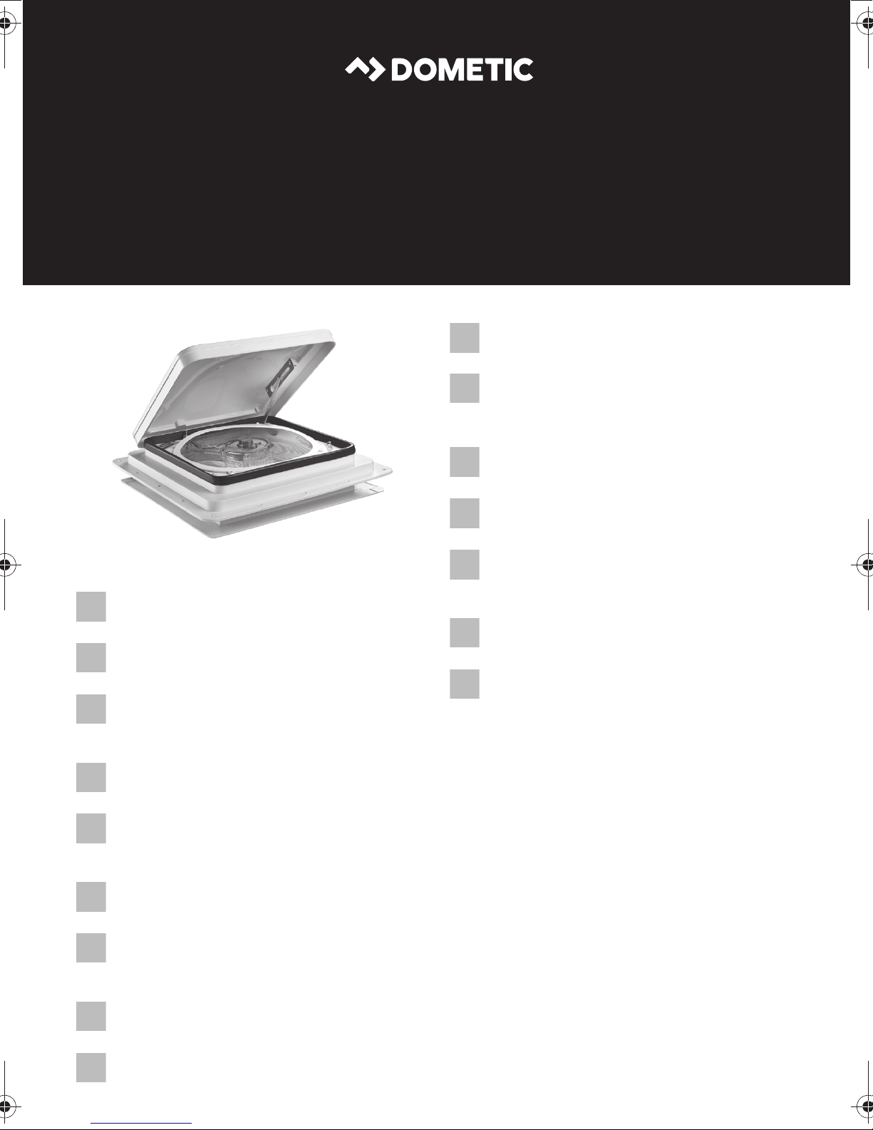
FanTastic Vent
Roof light with fan
Installation and Operating Manual. . . . . . . 13
Dachfenster mit Lüfter
Montage- und Bedienungsanleitung . . . . .27
Dôme de toit avec ventilateur
Instructions de montage
et de service . . . . . . . . . . . . . . . . . . . . . . . . . 41
Claraboya con ventilador
Instrucciones de montaje y de uso. . . . . . .55
Claraboia com ventilador
Instruções de montagem e manual de
instruções . . . . . . . . . . . . . . . . . . . . . . . . . . .69
Oblò da tetto con ventola
Istruzioni di montaggio e d’uso . . . . . . . . .83
Dakvenster met ventilator
Montagehandleiding en
gebruiksaanwijzing . . . . . . . . . . . . . . . . . . .97
Strešné okno s ventilátorom
Návod na montáž a uvedenie
do prevádzky. . . . . . . . . . . . . . . . . . . . . . . 195
Střešní okno s ventilátorem
Návod k montáži a obsluze . . . . . . . . . . . 209
Tetőablak ventilátorral
Szerelési és használati útmutató . . . . . . .223
Tagvindue med ventilator
Monterings- og betjeningsvejledning . . . 111
Tak fön ster m ed f läk t
Monterings- och bruksanvisning . . . . . . .125
Page 2
Page 3
FanTastic Vent
1
3
4
5
6
7
8
2
1
3
Page 4
12 mm
12 mm
Ø 24 mm
A
C
B
350 mm
350 mm
400 mm
400 mm
2
W
H
FanTastic Vent
3
A
B
2.
4
1.
4
Page 5
FanTastic Vent
350 x 350 mm:
5
1 – 2 mm
76
5
Page 6
8
FanTastic Vent
350 x 350 mm
6
400 x 400 mm
Page 7
FanTastic Vent
9
0
7
Page 8
a
b
FanTastic Vent
8
Page 9
FanTastic Vent
c
M
ANUAL
AU
%
T
100
O
9
0/
3
3
85
85/3
SP
EE
/
DOWN
0
70
8
D
0/27
55
7
5/2
4
40
TEM
7
0/2
P
1
25
6
5/1
8
10
6
0/15
R
A
IN
AI
S
R I
EN
SOR
N/OUTUP
OF
F
1.
2.
9
Page 10
d
FanTastic Vent
1
8
MANUAL
%
100
85
7
SPEED
70
55
40
25
10
AUTO
90/33
85/30
80/27
75/24
70/21
65/18
60/15
TEMP
2
3
4
AIR IN/OUTUP/DOWN
RAIN SENSOR OFF
6
5
10
Page 11
FanTastic Vent
1.
2.
3.
4.
e
f
2.
1.
11
Page 12
1.
g
FanTastic Vent
2.
12
Page 13

EN
FanTastic Vent
Please read this instruction manual carefully before installation and first
use, and store it in a safe place. If you pass on the product to another
person, hand over this instruction manual along with it.
Table of contents
1 Explanation of symbols . . . . . . . . . . . . . . . . . . . . . . . . . . . . . . . . . . . . . . . . . .14
2 Safety instructions . . . . . . . . . . . . . . . . . . . . . . . . . . . . . . . . . . . . . . . . . . . . . .14
3 Scope of delivery . . . . . . . . . . . . . . . . . . . . . . . . . . . . . . . . . . . . . . . . . . . . . .15
4 Intended use . . . . . . . . . . . . . . . . . . . . . . . . . . . . . . . . . . . . . . . . . . . . . . . . . .15
5 Technical description . . . . . . . . . . . . . . . . . . . . . . . . . . . . . . . . . . . . . . . . . . .16
6 Instructions before installation . . . . . . . . . . . . . . . . . . . . . . . . . . . . . . . . . . . .16
7 Installing the device . . . . . . . . . . . . . . . . . . . . . . . . . . . . . . . . . . . . . . . . . . . .17
8 Using the device (7350, 7300) . . . . . . . . . . . . . . . . . . . . . . . . . . . . . . . . . . .18
9 Using the device (3300, 3350) . . . . . . . . . . . . . . . . . . . . . . . . . . . . . . . . . . .21
10 Using the device (2250) . . . . . . . . . . . . . . . . . . . . . . . . . . . . . . . . . . . . . . . . 23
11 Maintaining and cleaning the device . . . . . . . . . . . . . . . . . . . . . . . . . . . . . . 23
12 Warranty . . . . . . . . . . . . . . . . . . . . . . . . . . . . . . . . . . . . . . . . . . . . . . . . . . . . 25
13 Disposal. . . . . . . . . . . . . . . . . . . . . . . . . . . . . . . . . . . . . . . . . . . . . . . . . . . . . 26
14 Technical data . . . . . . . . . . . . . . . . . . . . . . . . . . . . . . . . . . . . . . . . . . . . . . . . 26
13
Page 14
EN
Explanation of symbols FanTastic Vent
1 Explanation of symbols
WARNING!
!
Safety instruction: Failure to observe this instruction can cause fatal or
serious injury.
CAUTION!
Safety instruction: Failure to observe this instruction can lead to injury.
!
NOTICE!
A
Failure to observe this instruction can cause material damage and impair
the function of the product.
2 Safety instructions
Please observe the prescribed safety instructions and stipulations from the
vehicle manufacturer and service workshops.
The manufacturer accepts no liability for damage in the following cases:
• Damage to the product resulting from mechanical influences
• Alterations to the product without express permission from the manufacturer
• Use for purposes other than those described in the operating manual
Please note the following:
• If faults or disturbances occur, consult a specialist workshop immediately.
• Risk of breakage! Do not tread on the plastic dome.
• Before starting your journey, check that the roof light is closed.
• Before starting your journey, check the roof light for damage (such as tension
cracks in the cover hood).
• Do not open the roof light while driving.
• Do not open the roof light in strong wind or rain.
• Close the roof light if it rains or snows.
• Do not leave the vehicle with the roof light open.
14
Page 15
EN
FanTastic Vent Scope of delivery
• Keep the roof light free of snow and ice.
• Close the cover hood of the roof light, before the vehicle is in motion.
• With closed cover hood, do not exceed the maximum travel speed of 150 km/h.
3Scope of delivery
Quantity Description
1 Roof light with fan
1 Seal (only for 350 x 350 mm fan base)
1 Inner frame
6 Fastening screws (3/4" (19.05 mm)) for the inner frame
8 Fastening screws (1" (25.4 mm)) for the roof installation of the fan
1 Remote control (only 7350, 7300)
1 Installation and operating manual
4 Intended use
This roof light with FanTastic Vent fan is suitable for installation in motor homes and
caravans.
The cover hood of the roof light must be closed, before the vehicle is in motion.
With closed cover hood, the maximum travel speed permitted is 150 km/h, as noise
or damage could occur depending on the vehicle design or installation position.
15
Page 16
EN
Technical description FanTastic Vent
5 Technical description
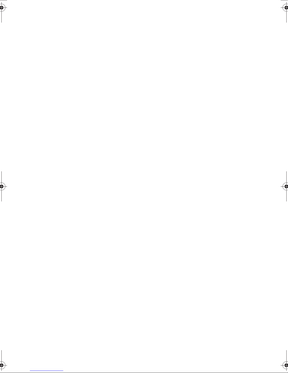
5.1 Components
No. in
fig. 1,
page 3
1Cover hood
2 Top grille ring
3 Fan blades
4 Fan blade screw
5 Fan base
6 Grille assembly
Description
7 Hoist motor assembly
8 Bottom grille ring
6 Instructions before installation
➤ Before installation, check the roof thickness of your vehicle. Consult the vehicle
manufacturer if you have any questions.
➤ When choosing the installation location, observe the following:
– Select the installation location so that it is as near to a 12 V connection as
possible.
– Adjoining components (roof rack or attachment and reinforcing parts), cables
and cabinets in the vehicle interior must not get damaged when sawing the
hole.
– Only fit the roof light on flat and parallel interior and exterior roof areas with a
maximum inclination of 15° to the horizontal.
You may use an existing roof hole provided the roof light fits into it.
16
Page 17
EN
FanTastic Vent Installing the device
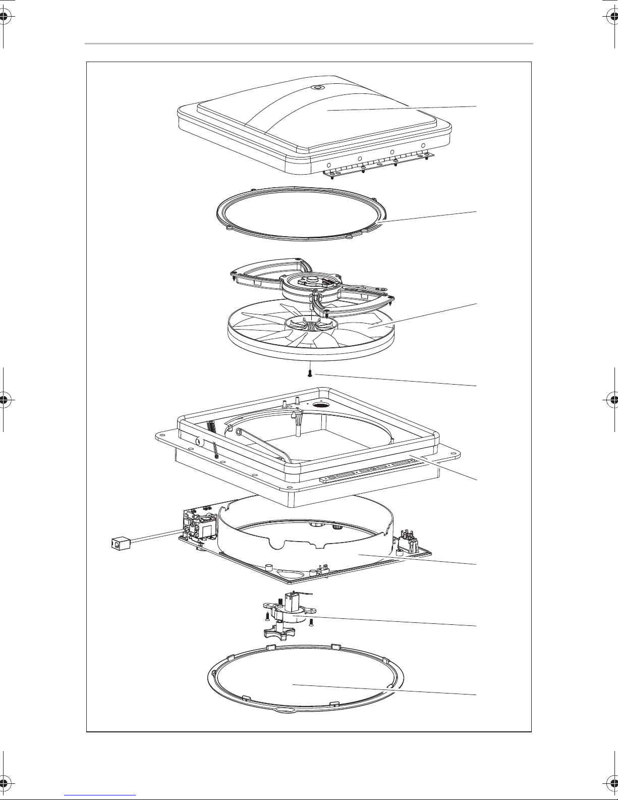
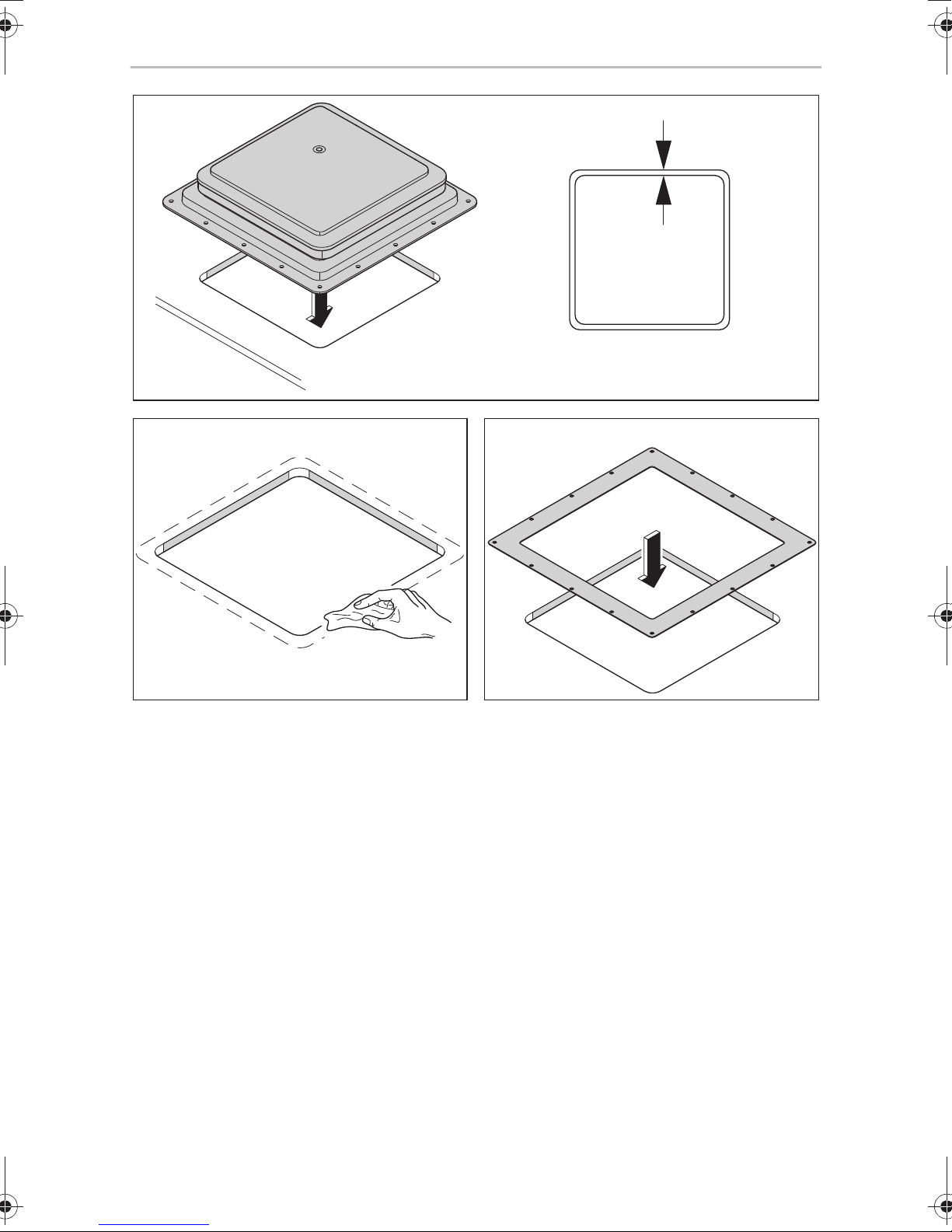
6.1 Pressing out the hole
See fig. 2, page 4
6.2 Using the reinforcing rails
Proceed as follows (fig. 3, page 4):
➤ Before installation, check whether the roof opening needs reinforcing.
➤ Remove the foam according to the width of the reinforcing rails (not in scope of
delivery) (A).
➤ Fit the reinforcing rails (B).
7 Installing the device
WARNING! Beware of injury!
!
➤ Run the 12 V connection through the roof.
➤ Trim the inner frame depending on the thickness of the roof (fig. 4, page 4).
➤ Check that the roof light has sufficient space around it (approx.1 to 2 mm) in the
roof opening (fig. 5, page 5).
➤ Clean the roof opening in the mounting area (fig. 6, page 5).
➤ Place a gasket or sealant around the roof opening (fig. 7, page 5).
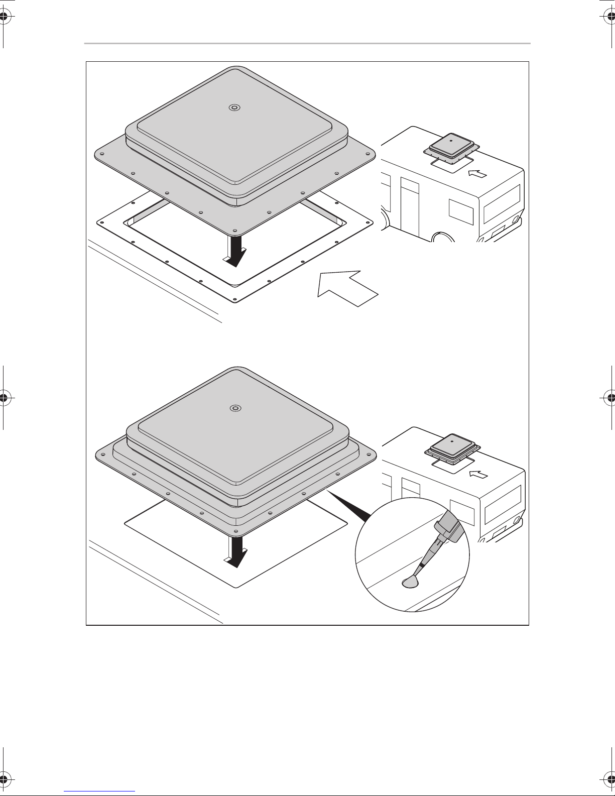
➤ Check the direction of travel when installing (fig. 8, page 6).
➤ Make sure the cover hood hinge is towards the direction of travel.
➤ Place the roof light into the middle of the roof opening (fig. 8, page 6).
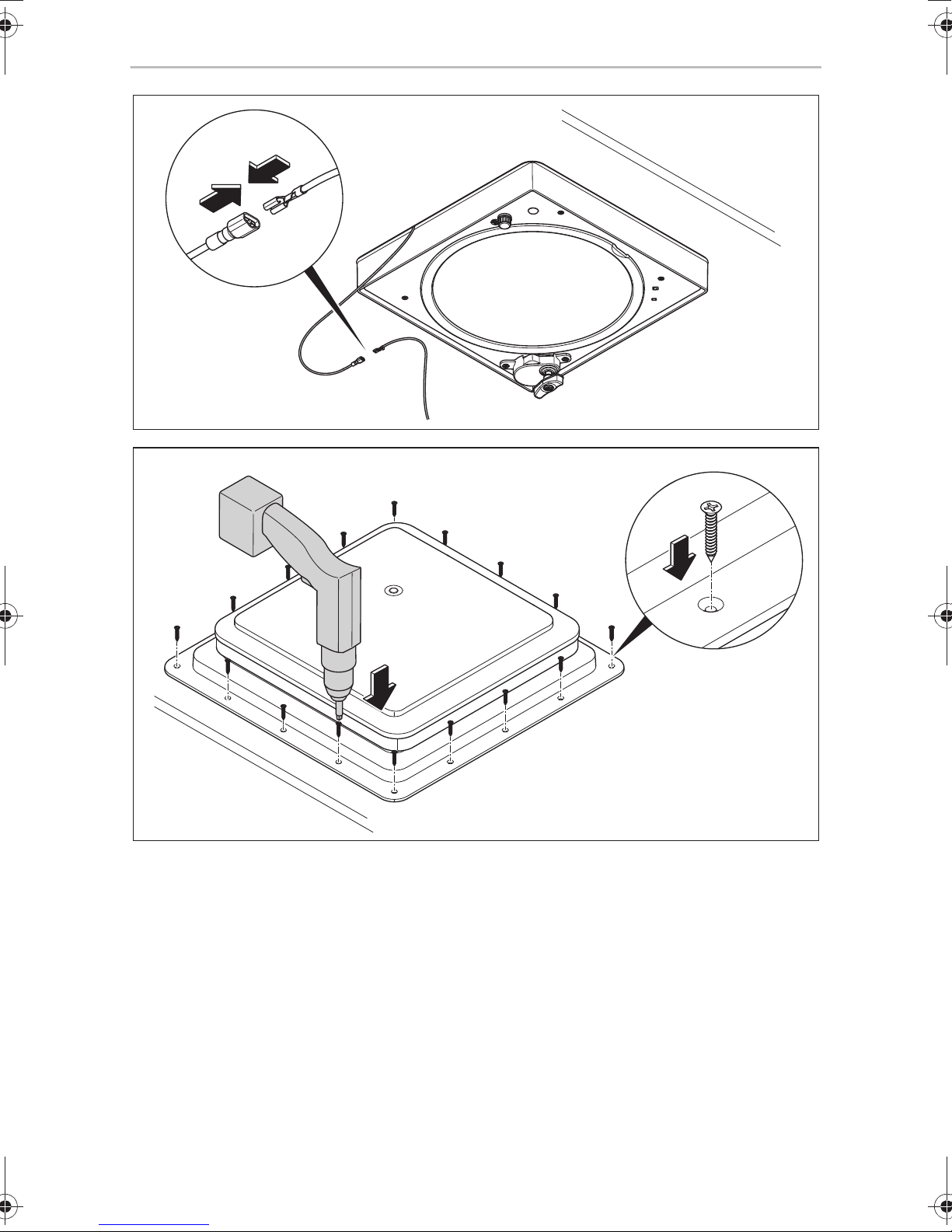
➤ Connect the cable to the 12 V connection (fig. 9, page 7).
Disconnect the vehicle power supply before you begin and make sure it
cannot be restarted.
➤ Check the fan works properly.
➤ Screw the roof light to the roof tightly. Use all the screw holes provided to do this
(fig. 0, page 7).
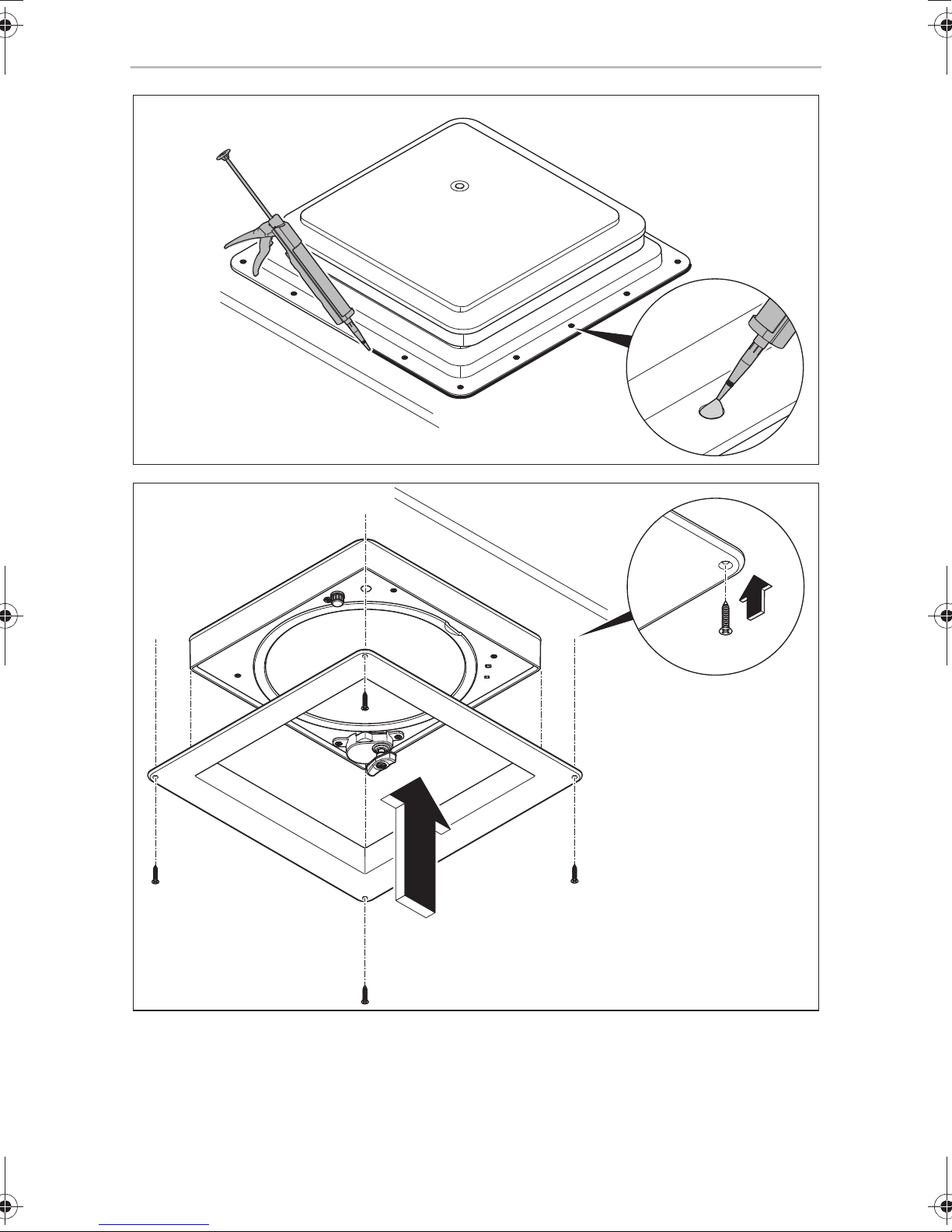
➤ Seal the roof light (fig. a, page 8).
➤ Seal the screw heads (fig. a, page 8).
17
Page 18
EN
Using the device (7350, 7300) FanTastic Vent
➤ If the roof is thinner than 25 mm, use the spacer (accessory).
➤ Install the inner frame (fig. b, page 8).
➤ After installing, check again the fan works properly.
➤ If necessary, enter the new vehicle height and weight in the vehicle documents.
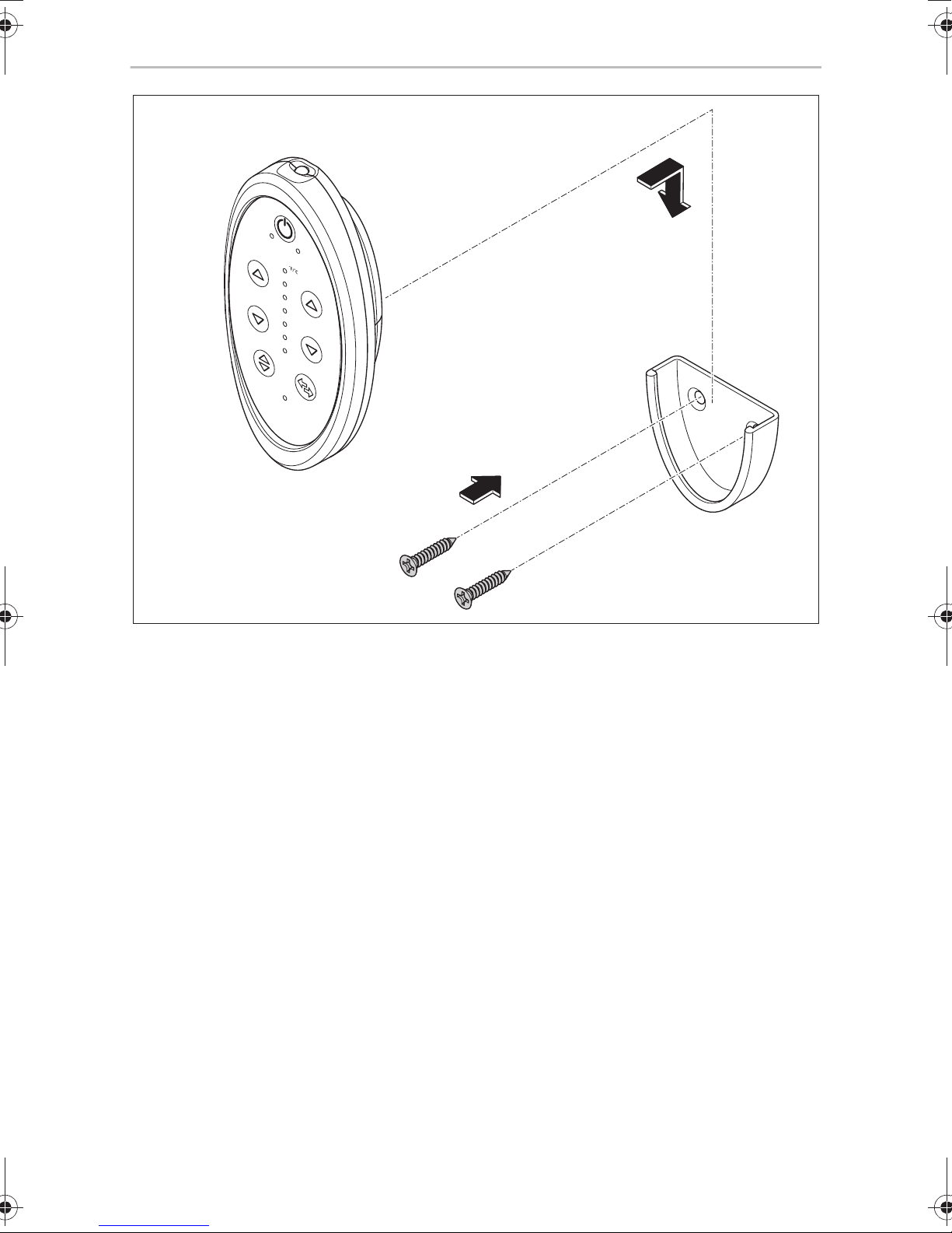
7.1 Mounting the holder for the remote control
(7350, 7300)
➤ Fasten the holder of the remote control onto the wall with two screws (fig. c,
page 9).
8 Using the device (7350, 7300)
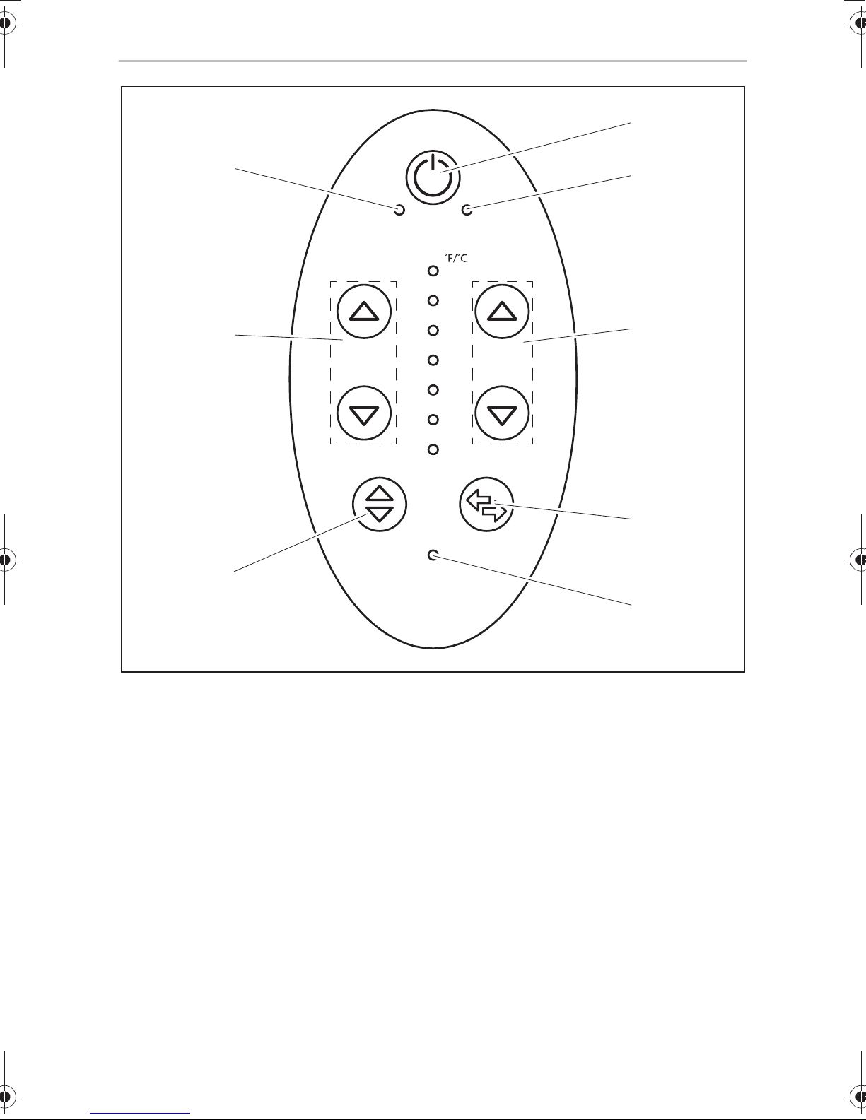
8.1 Control elements
The remote control has the following buttons and displays:
No. in
fig. d,
page 10
1 To switch the fan on/off
2 “Auto” LED
3 To set the temperature
4 To set the outlet/inlet air (for 7350 and 6350 only)
5 “Rain Sensor Off” LED
6 Press briefly: To open/close the cover hood
7 To set the fan speed
Description
Press for 3 seconds: To switch the rain sensor on/off
8 “Manual” LED
The fan control confirms commands from the remote control with a beep. If a single
beep is not emitted, the command has not been received.
A double beep indicates that a command is not permitted.
18
Page 19
EN
FanTastic Vent Using the device (7350, 7300)
The remote control goes into standby mode to conserve the battery 30 seconds
after entering the last command. To activate the remote control, press any button on
the remote. The last temperature or speed setting before it goes into standby is
displayed. If the remote control is switched off manually with the
settings are reset.
button, all the
8.2 Opening and closing the cover hood
➤ Briefly press the button.
✓ The cover hood opens.
➤ Briefly press the
✓ The cover hood closes.
button.
8.3 Switching the fan on and off
The fan is fitted with a safety switch. You can only switch on the fan if the cover hood
is open.
➤ Open the window on the shady side of the caravan.
➤ Press the
✓ The fan starts automatically.
➤ Press the
✓ The fan switches itself off.
✓ The cover hood closes.
button.
button.
8.4 Setting the temperature
The temperature can be set at 13 levels. The set temperature is displayed with an LED
on the remote control in °F and °C (60 – 90 °F/15 – 33 °C). If two LEDs light up, the
temperature setting is in the middle between the illuminated values. (Example: If the
LEDs for 80 °F and 85 °F light up, the setting is at approx. 83 °F/28 °C).
➤ Press the or (temperature) button to change to the automatic mode.
✓ The “Auto” LED lights up.
➤ Press the button to increase the required temperature.
➤ Press the button to decrease the required temperature.
19
Page 20
EN
Using the device (7350, 7300) FanTastic Vent
8.5 Setting the fan speed
The fan can be operated at 13 speeds. The fan speed is displayed with an LED on the
remote control from 10 % (low speed) to 100 % (high speed). An LED lights up next
to the percentage value of the fan speed. If two LEDs light up, the temperature
setting is in the middle between the illuminated percentage values.
➤ Press the or (speed) button to change to the manual mode.
✓ The “Manual” LED lights up.
➤ Press the button to increase the speed.
➤ Press the button to decrease the speed.
8.6 Switching the outlet/inlet air
➤ Press the button.
✓ The fan switches from outlet air to inlet air and vice versa.
8.7 Switching the rain sensor on and off
➤ Press and hold the button for 3 seconds.
✓ The rain sensor switches itself off.
✓ The “Rain Sensor Off” LED lights up.
➤ Press and hold the button for 3 seconds.
✓ The rain sensor switches itself on.
✓ The “Rain Sensor Off” LED goes out.
20
Page 21

EN
FanTastic Vent Using the device (3300, 3350)
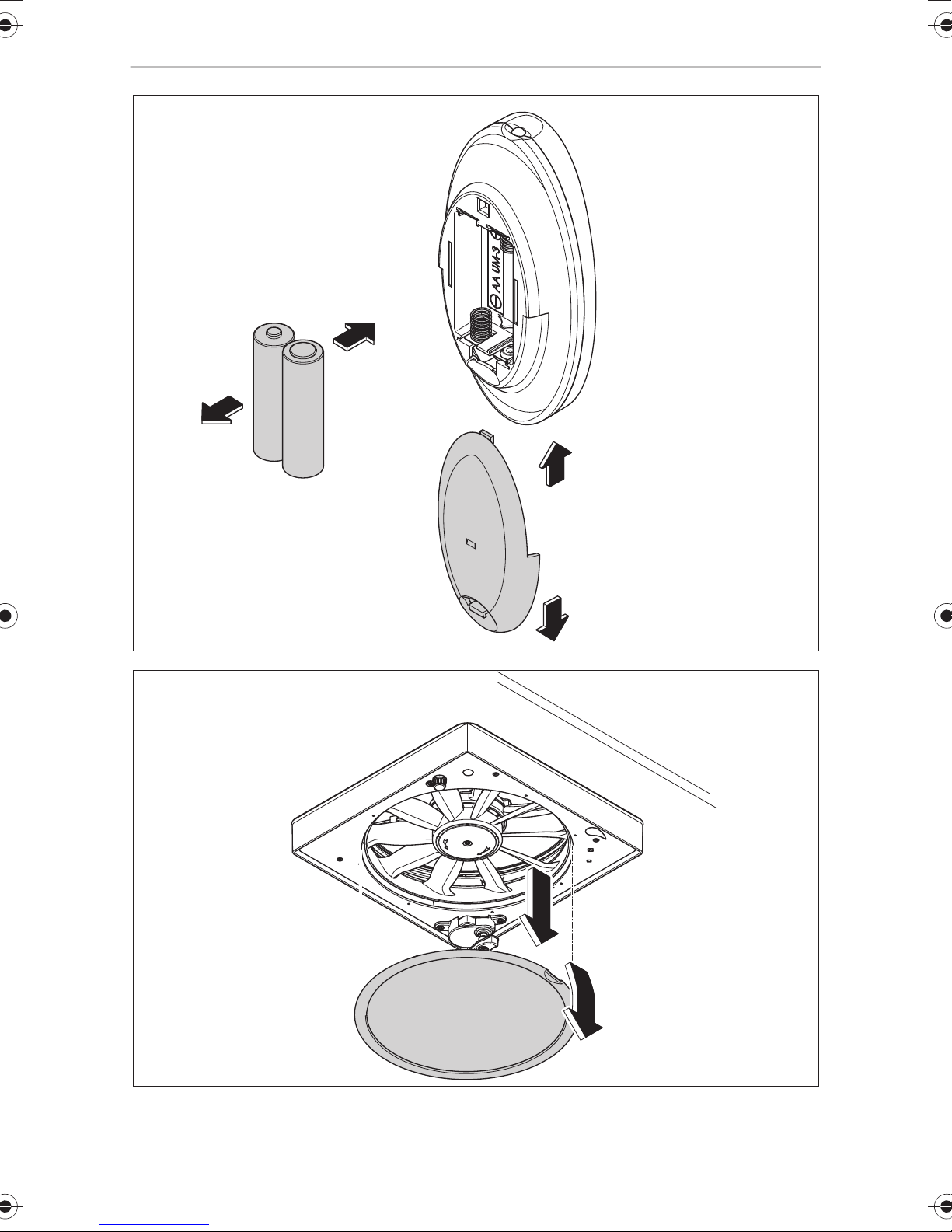
8.8 Replacing the batteries
The remote control operates with two AA batteries (included in delivery).
To change the batteries (fig. e, page 11), proceed as follows:
➤ Open the cover of the battery compartment on the back of the remote control.
➤ Replace the old batteries with two new AA batteries. Make sure that the positive
and negative terminals of the batteries correspond to the positive and negative
markings in the battery compartment.
➤ To close the battery compartment, place the alignment tab into the square hole
on the back of the remote control.
➤ Press the lid of the battery compartment down until the catch clicks into place.
9 Using the device (3300, 3350)
9.1 Control elements
The fan has the following control elements:
• A switch with four speeds (0: off, 1: low, 2: medium, 3: high)
• Rocker switch for opening/closing the cover hood (UP/DOWN)
• On/Off switch (3300 only)
• Reversing switch for outlet/inlet (3350 only)
• Thermostat switch
9.2 Opening and closing the cover hood
➤ Press UP.
✓ The cover hood opens.
➤ Press DOWN
✓ The cover hood closes.
.
21
Page 22
EN
Using the device (3300, 3350) FanTastic Vent
9.3 Switching the fan on and off
➤ Open the window on the shady side of the caravan.
➤ Set the required speed on the fan.
➤ Press UP.
➤ Set the fan, if required, to inlet (IN) or outlet (OUT).
➤ If required, turn the on/off switch to ON.
9.4 Switching to inlet/outlet (3350 only)
➤ Turn the reversing switch to OFF (centre position).
➤ Wait until the fan blades have come to a complete standstill.
➤ Set the reversing switch to the required rotating direction.
9.5 Setting the thermostat
You can set the thermostat switch between blue and red (–5.5 °C to 50.5 °C / 22 °F
to 123 °F). The fan motor switches itself on or off according to the interior temperature and thermostat setting.
When the set temperature is reached, the fan motor switches off and the cover hood
remains open.
When the thermostat calls for cooling, the fan motor switches on automatically.
Requirements:
• Cover hood is open by at least 5 cm (2 inches)
• Reversing switch is set to OUT (outlet) or IN (inlet) (3350)
• On/Off switch is set to ON (3300)
9.6 Rain sensor
If the rain sensor comes into contact with moisture, the cover hood closes and the fan
motor is switched off.
➤ Press UP to open the cover hood again.
✓ The fan starts working again with the previous settings.
✓ The rain sensor is only activated again once it has dried.
22
Page 23

EN
FanTastic Vent Using the device (2250)
10 Using the device (2250)
10.1 Opening and closing the cover hood
➤ Open the cover hood approx. 10 cm or more.
✓ The safety switch starts the fan not before the cover hood is partially open.
➤ Adjust the power level with the rotary control switch
– 0: Off
– 1: Lowest power level
– 2: Middle power level
– 3: Highest power level
➤ For an air exchange, open a window or a door.
✓ To get the best air exchange, close all other roof openings and open exactly one
window, which has the greatest distance from the device.
.
11 Maintaining and cleaning the device
11.1 Replacing the fuse
➤ Turn the black cap anti-clockwise by one-quarter turn.
➤ Pull the cap down gently. The fuse is on the back of the cap.
➤ Check whether the wire is defective within the glass.
➤ If necessary, remove the fuse from the cap.
➤ Insert a new fuse of the same type (4 A fuse).
➤ Screw the cap back on again tightly.
23
Page 24
EN
Maintaining and cleaning the device FanTastic Vent
11.2 Cleaning the fan blades
To do this, proceed as follows (fig. f, page 11, fig. g, page 12):
➤ Open the cover hood completely.
➤ Remove the safety catch.
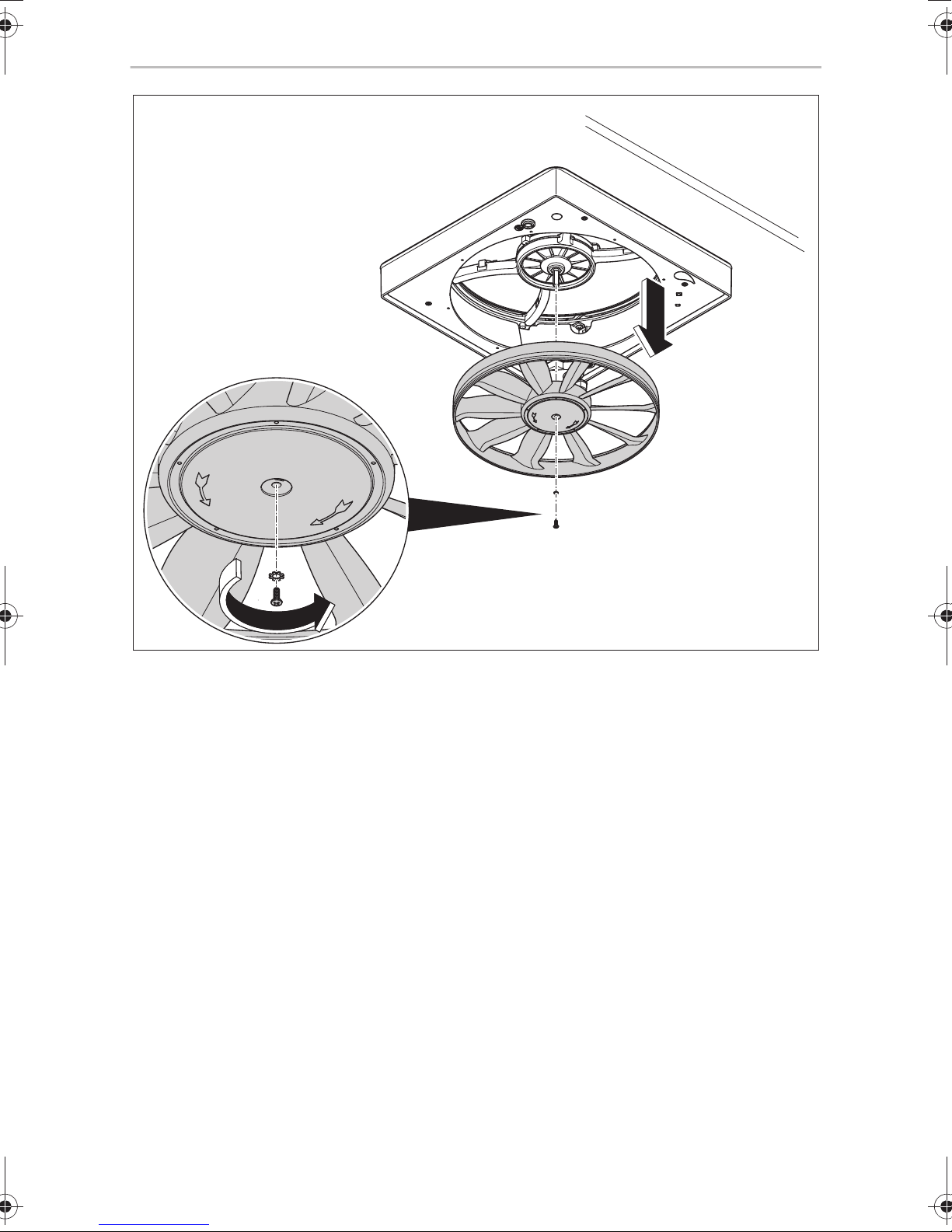
➤ Remove the grille ring by holding the tab with one hand and pulling straight
down.
Support the grille assembly with the other hand to protect the grille ring from
breaking. Removing the grille ring may initially be difficult but once you have
disassembled it several times it gets easier.
➤ Hold the fan blades with one hand so that it does not rotate and remove the
screw from the hub surface in the middle of the fan blade.
➤ Hold the fan blades with both hands and pull down firmly.
Move the fan blades bit by bit vertically and horizontally if necessary, so that it
slides off the motor shaft.
➤ Clean the grille ring and the fan blades
– with window cleaner
– with non-abrasive detergent and warm water
– in a dishwasher
➤ Once the grille ring and fan blades are clean and dry, you can apply a water-
based protective agent and polish the grille ring and fan blades to a high gloss.
This reduces dust and dirt deposits and makes cleaning easier.
➤ Reassemble the fan again by following the steps in reverse order.
CAUTION! Beware of injury.
Only use the fan when the grille ring is fitted.
!
24
Page 25

EN
FanTastic Vent Warranty
11.3 Loosening the cover hood when stuck
In warm weather, it is possible that the seal dries up and the cover hood sticks to it.
➤ Open the cover hood completely.
➤ If the seal is damaged, replace the seal.
➤ Clean the underside of the cover hood and the seal with methylated spirits or
solvent.
➤ If available, apply a water-based protective agent (e.g. 303 Protectant).
➤ Leave the protective agent to dry.
➤ Polish the cover hood with a soft cloth.
➤ Apply an even layer of silicone on the seal.
11.4 Looking after the remote control
➤ Keep the remote control dry. If it gets wet, wipe it dry immediately.
➤ Only use and store the remote control in environments with normal
temperatures.
➤ Keep the remote control clean. If necessary, wipe it with a damp cloth.
➤ Be careful when using the remote control. Do not drop it.
12 Warranty
The statutory warranty period applies. If the product is defective, please contact the
service partner in your country (addresses on the back on the instruction manual).
Our experts will be happy to help you and will discuss the warranty process with you
in more detail.
25
Page 26
EN
Disposal FanTastic Vent
13 Disposal
➤ Place the packaging material in the appropriate recycling waste bins wherever
possible.
If you wish to finally dispose of the product, ask your local recycling centre
or specialist dealer for details about how to do this in accordance with the
M
applicable disposal regulations.
14 Technical data
FanTastic Vent7350
Voltage: 12 Vg
Max. power consumption: 30 W
Noise level: < 40 dB(A)
Dimensions W x D x H: 471 x 471 x 190 mm
Weight: 5 kg
FanTastic Vent2250 – 7300
Voltage: 12 Vg
Max. power consumption: 36 W
Noise level: < 40 dB(A)
Dimensions W x D x H: 471 x 471 x 190 mm
Weight: 5 kg
26
Page 27
DE
FanTastic Vent
Bitte lesen Sie diese Anleitung vor Einbau und Inbetriebnahme sorgfältig
durch und bewahren Sie sie auf. Geben Sie sie im Falle einer Weitergabe
des Produktes an den Nutzer weiter.
Inhaltsverzeichnis
1 Erklärung der Symbole . . . . . . . . . . . . . . . . . . . . . . . . . . . . . . . . . . . . . . . . . 28
2 Sicherheits- und Einbauhinweise . . . . . . . . . . . . . . . . . . . . . . . . . . . . . . . . . 28
3 Lieferumfang . . . . . . . . . . . . . . . . . . . . . . . . . . . . . . . . . . . . . . . . . . . . . . . . . 29
4 Bestimmungsgemäßer Gebrauch . . . . . . . . . . . . . . . . . . . . . . . . . . . . . . . . 29
5 Technische Beschreibung . . . . . . . . . . . . . . . . . . . . . . . . . . . . . . . . . . . . . . 30
6 Hinweise vor dem Einbau. . . . . . . . . . . . . . . . . . . . . . . . . . . . . . . . . . . . . . . 30
7 Gerät montieren . . . . . . . . . . . . . . . . . . . . . . . . . . . . . . . . . . . . . . . . . . . . . . .31
8 Gerät benutzen (7350, 7300) . . . . . . . . . . . . . . . . . . . . . . . . . . . . . . . . . . . 32
9 Gerät benutzen (3300, 3350) . . . . . . . . . . . . . . . . . . . . . . . . . . . . . . . . . . . 35
10 Gerät benutzen (2250) . . . . . . . . . . . . . . . . . . . . . . . . . . . . . . . . . . . . . . . . . 37
11 Gerät pflegen und reinigen . . . . . . . . . . . . . . . . . . . . . . . . . . . . . . . . . . . . . 37
12 Gewährleistung. . . . . . . . . . . . . . . . . . . . . . . . . . . . . . . . . . . . . . . . . . . . . . . 40
13 Entsorgung . . . . . . . . . . . . . . . . . . . . . . . . . . . . . . . . . . . . . . . . . . . . . . . . . . 40
14 Technische Daten . . . . . . . . . . . . . . . . . . . . . . . . . . . . . . . . . . . . . . . . . . . . . 40
27
Page 28
DE
Erklärung der Symbole FanTastic Vent
1 Erklärung der Symbole
WARNUNG!
!
Sicherheitshinweis: Nichtbeachtung kann zu Tod oder schwerer
Verletzung führen.
VORSICHT!
Sicherheitshinweis: Nichtbeachtung kann zu Verletzungen führen.
!
ACHTUNG!
A
Nichtbeachtung kann zu Materialschäden führen und die Funktion des
Produktes beeinträchtigen.
2 Sicherheits- und Einbauhinweise
Beachten Sie die vom Fahrzeughersteller und vom Kfz-Handwerk vorgeschriebenen Sicherheitshinweise und Auflagen!
Der Hersteller übernimmt in folgenden Fällen keine Haftung für Schäden:
• Beschädigungen am Produkt durch mechanische Einflüsse
• Veränderungen am Produkt ohne ausdrückliche Genehmigung vom Hersteller
• Verwendung für andere als die in der Anleitung beschriebenen Zwecke
Beachten Sie folgende Hinweise:
• Suchen Sie umgehend eine Fachwerkstatt auf, wenn Fehler oder Störungen
auftreten.
• Einbruchgefahr! Betreten Sie die Plastikkuppel nicht.
• Kontrollieren Sie vor Fahrtantritt, ob das Dachfenster geschlossen ist.
• Kontrollieren Sie vor Fahrtantritt das Dachfenster auf Beschädigungen (z. B.
Spannungsrisse in der Deckelhaube).
• Öffnen Sie das Dachfenster nicht während der Fahrt.
• Öffnen Sie das Dachfenster nicht bei starkem Wind oder Regen.
• Schließen Sie das Dachfenster bei Regen und Schneefall.
• Verlassen Sie das Fahrzeug nicht bei geöffnetem Dachfenster.
• Halten Sie das Dachfenster schnee- und eisfrei.
28
Page 29
DE
FanTastic Vent Lieferumfang
• Schließen Sie die Deckelhaube des Dachfensters, bevor Sie das Fahrzeug bewegen.
• Bei geschlossener Deckelhaube empfiehlt der Hersteller ausdrücklich eine maximale Reisegeschwindigkeit von 150 km/h nicht zu überschreiten.
3 Lieferumfang
Menge Bezeichnung
1 Dachfenster mit Lüfter
1 Dichtung (nur bei 350 x 350 mm Lüfter)
1Innenrahmen
6 Befestigungsschrauben (3/4“ (19.05 mm)) für den inneren Rahmen
8 Befestigungsschrauben (1“ (25.4 mm)) für die Dachinstallation des Lüfters
1 Fernbedienung (nur 7350, 7300)
1 Montage- und Bedienungsanleitung
4 Bestimmungsgemäßer Gebrauch
Das Dachfenster mit Lüfter FanTastic Vent ist geeignet zum Einbau in Wohnmobile
oder Wohnwagen.
Die Deckelhaube des Dachfenster muss geschlossen werden, bevor das Fahrzeug
bewegt wird.
Bei geschlossener Deckelhaube empfiehlt der Hersteller ausdrücklich die maximal
erlaubte Fahrgeschwindigkeit von 150 km/h nicht zu überschreiten, da je nach
Fahrzeugaufbau oder Einbauposition Geräuschentwicklungen oder
Beschädigungen auftreten können.
29
Page 30

DE
Technische Beschreibung FanTastic Vent
5 Technische Beschreibung
5.1 Bestandteile
Nr. in
Abb. 1,
Seite 3
1Deckelhaube
2 Oberer Gitterring
3 Lüfterflügel
4 Lüfterflügelschraube
5Lüftersockel
6 Gitterbaugruppe
Beschreibung
7 Hubmotorbaugruppe
8 Unterer Gitterring
6 Hinweise vor dem Einbau
➤ Prüfen Sie vor der Montage die Dachstärke lhres Fahrzeugs. Bei Fragen wenden
Sie sich an den Fahrzeughersteller.
➤ Beachten Sie bei der Wahl des Einbauortes:
– Wählen Sie den Einbauort so, dass er möglichst nah an einem 12 V-Anschluss
liegt.
– Angrenzende Bauteile (Dachreling oder Befestigungs- und Verstär-
kungsteile), Leitungen und Einbauschränke im Fahrzeuginnenraum dürfen
beim Sägen des Ausschnitts nicht beschädigt werden.
– Montieren Sie das Dachfenster nur an planen und parallelen Innen- und
Außendachflächen mit einer maximalen Schrägstellung von 15° gegenüber
der Horizontalen.
Sie können einen vorhandenen Dachausschnitt verwenden, wenn das Dachfenster
hinein passt.
30
Page 31

DE
FanTastic Vent Gerät montieren
6.1 Ausschnitt ausarbeiten
Siehe Abb. 2, Seite 4
6.2 Verstärkungsleisten verwenden
Gehen Sie wie folgt vor (Abb. 3, Seite 4):
➤ Klären Sie vor dem Einbau, ob der Dachausschnitt verstärkt werden muss.
➤ Entfernen Sie die Ausschäumung entsprechend der Breite der Verstärkungs-
leisten (nicht im Lieferumfang) (A).
➤ Passen Sie die Verstärkungsleisten ein (B).
7Gerät montieren
WARNUNG! Verletzungsgefahr!
!
➤ Verlegen Sie den 12 V-Anschluss durch das Dach.
➤ Kürzen Sie den Innenrahmen je nach Dachstärke (Abb. 4, Seite 4).
➤ Prüfen Sie, ob das Dachfenster rundum genügend Abstand (ca. 1 – 2 mm) zum
Dachausschnitt hat (Abb. 5, Seite 5).
➤ Reinigen Sie den Dachausschnitt im Montagebereich (Abb. 6, Seite 5).
➤ Platzieren Sie eine Dichtung oder Dichtungsmittel um den Dachausschnitt
(Abb. 7, Seite 5).
➤ Beachten Sie bei der Montage die Fahrtrichtung (Abb. 8, Seite 6).
➤ Stellen Sie sicher, dass das Gelenk der Deckelhaube zur Fahrtrichtung hin mon-
tiert ist.
➤ Setzen Sie das Dachfenster mittig in den Dachausschnitt ein (Abb. 8, Seite 6).
Schalten Sie das Fahrzeug vor Beginn der Montage spannungsfrei und
sichern Sie es gegen Wiedereinschalten.
➤ Verbinden Sie das Anschlusskabel mit dem 12 V-Anschluss (Abb. 9, Seite 7).
➤ Prüfen Sie die Funktion des Lüfters.
➤ Schrauben Sie das Dachfenster am Dach fest. Verwenden Sie dabei alle
vorhandenen Schraublöcher (Abb. 0, Seite 7).
➤ Dichten Sie das Dachfenster ab (Abb. a, Seite 8).
31
Page 32

DE
Gerät benutzen (7350, 7300) FanTastic Vent
➤ Dichten Sie die Schraubenköpfe ab (Abb. a, Seite 8).
➤ Wenn das Dach dünner als 25 mm ist, verwenden Sie Abstandshalter (Zubehör).
➤ Installieren Sie den Innenrahmen (Abb. b, Seite 8).
➤ Prüfen Sie nach der Montage erneut die Funktion des Lüfters.
➤ Lassen Sie die geänderte Fahrzeughöhe und das geänderte Gewicht in die
Fahrzeugpapiere eintragen, falls erforderlich.
7.1 Halter der Fernbedienung montieren (7350, 7300)
➤ Befestigen Sie den Halter der Fernbedienung mit zwei Schrauben an der Wand
(Abb. c, Seite 9).
8 Gerät benutzen (7350, 7300)
8.1 Bedienelemente
Die Fernbedienung hat folgende Tasten und Anzeigen:
Nr. in
Abb. d,
Seite 10
1 Lüfter ein-/ausschalten
2LED „Auto“
3 Temperatur einstellen
4 Abluft/Zuluft einstellen (nur bei 7350 und 6350)
5 LED „Rain Sensor Off“ (Regensensor aus)
6 kurz drücken: Deckelhaube öffnen/schließen
7 Lüftergeschwindigkeit einstellen
Beschreibung
3 s lang drücken: Regensensor ein-/ausschalten
8 LED „Manual“
Die Lüftersteuerung bestätigt Befehlseingaben von der Fernbedienung mit einem
Piepton. Wenn kein einzelner Piepton ertönt, wurde der Befehl nicht empfangen.
32
Page 33

DE
FanTastic Vent Gerät benutzen (7350, 7300)
Ein doppelter Piepton gibt an, dass ein Befehl nicht zulässig ist.
Die Fernbedienung geht 30 Sekunden nach der letzten Befehlseingabe in den
Standby-Modus über, um die Batterie zu schonen. Um die Fernbedienung zu
aktivieren, drücken Sie eine beliebige Taste auf der Fernbedienung. Die letzte
Temperatur- oder Drehzahleinstellung vor dem Standby wird angezeigt. Wird die
Fernbedienung mit der Taste
zurückgesetzt.
manuell ausgeschaltet, werden alle Einstellungen
8.2 Deckelhaube öffnen und schließen
➤ Drücken Sie kurz die Taste .
✓ Die Deckelhaube öffnet sich.
➤ Drücken Sie kurz die Taste
✓ Die Deckelhaube schließt sich.
.
8.3 Lüfter ein- und ausschalten
Der Lüfter ist mit einem Sicherheitsschalter ausgestattet. Sie können den Lüfter nur
einschalten, wenn die Deckelhaube geöffnet ist.
➤ Öffnen Sie ein Fenster auf der schattigen Seite des Wohnwagens.
➤ Drücken Sie die Taste
✓ Der Lüfter startet im Automatik-Modus.
➤ Drücken Sie die Taste
✓ Der Lüfter schaltet sich aus.
✓ Die Deckelhaube schließt sich.
.
.
8.4 Temperatur einstellen
Die Temperatur kann in 13 Stufen eingestellt werden. Die eingestellte Temperatur
wird durch eine leuchtende LED auf der Fernbedienung in °F und °C angezeigt
(60 – 90 °F/15 – 33 °C). Wenn zwei LEDs leuchten, liegt die Temperatureinstellung
in der Mitte zwischen den beleuchteten Gradwerten. (Beispiel: Wenn die LEDs für
80 °F und 85 °F leuchten, beträgt die Einstellung etwa 83 °F/28 °C).
➤ Drücken Sie die Taste oder (Temp), um in den Automatik-Modus zu
wechseln.
✓ Die LED „Auto“ leuchtet.
33
Page 34

DE
Gerät benutzen (7350, 7300) FanTastic Vent
➤ Drücken Sie die Taste , um die gewünschte Temperatur zu erhöhen.
➤ Drücken Sie die Taste , um die gewünschte Temperatur zu verringern.
8.5 Lüftergeschwindigkeit einstellen
Der Lüfter kann in 13 Geschwindigkeitsstufen betrieben werden. Die Lüftergeschwindigkeit wird durch eine leuchtende LED auf der Fernbedienung von 10 %
(niedrige Geschwindigkeit) bis 100 % (hohe Geschwindigkeit) angezeigt. Eine LED
leuchtet neben dem Prozentwert der Lüftergeschwindigkeit. Wenn zwei LEDs leuchten, liegt die Lüftergeschwindigkeit in der Mitte zwischen den beleuchteten Prozentwerten.
➤ Drücken Sie die Taste oder (Speed), um in den manuellen Modus zu
wechseln.
✓ Die LED „Manual“ leuchtet.
➤ Drücken Sie die Taste , um die Geschwindigkeit zu erhöhen.
➤ Drücken Sie die Taste , um die Geschwindigkeit zu verringern.
8.6 Zuluft/Abluft umschalten
➤ Drücken Sie die Taste .
✓ Der Lüfter schaltet von Zuluft auf Abluft und umgekehrt.
8.7 Regensensor ein- und ausschalten
➤ Halten Sie die Taste 3 Sekunden lang gedrückt.
✓ Der Regensensor schaltet sich aus.
✓ Die LED „Rain Sensor Off“ leuchtet.
➤ Halten Sie die Taste 3 Sekunden lang gedrückt.
✓ Der Regensensor schaltet sich ein.
✓ Die LED „Rain Sensor Off“ erlischt.
34
Page 35

DE
FanTastic Vent Gerät benutzen (3300, 3350)
8.8 Batterien wechseln
Die Fernbedienung wird mit zwei AA-Batterien (im Lieferumfang enthalten)
betrieben.
Gehen Sie wie folgt vor, um die Batterien zu wechseln (Abb. e, Seite 11):
➤ Öffnen Sie den Batteriefachdeckel auf der Rückseite der Fernbedienung.
➤ Ersetzen Sie die alten Batterien durch zwei neue AA-Batterien. Achten Sie darauf,
dass die Plus- und Minuspole der Batterien mit den Plus- und Minus-Markierungen im Batteriefach übereinstimmen.
➤ Um den Batteriefachdeckel zu schließen, setzen Sie die Ausrichtungszunge in
die quadratische Öffnung auf der Rückseite der Fernbedienung.
➤ Drücken Sie den Batteriefachdeckel nach unten, bis die Lasche mit einem Klicken
einrastet.
9 Gerät benutzen (3300, 3350)
9.1 Bedienelemente
Der Lüfter hat folgende Bedienelemente:
• vierstufiger Geschwindigkeitssregler (0: Aus, 1: Niedrig, 2: Mittel, 3: Hoch)
• Wippschalter zum Öffnen/Schließen der Deckelhaube (UP/DOWN)
• Ein-/Ausschalter (nur 3300)
• Reversierschalter für Abluft/Zuluft (nur 3350)
• Thermostatschalter
9.2 Deckelhaube öffnen und schließen
➤ Drücken Sie auf UP.
✓ Die Deckelhaube öffnet sich.
➤ Drücken Sie auf DOWN
.
✓ Die Deckelhaube schließt sich.
35
Page 36

DE
Gerät benutzen (3300, 3350) FanTastic Vent
9.3 Lüfter ein- und ausschalten
➤ Öffnen Sie ein Fenster auf der schattigen Seite des Wohnwagens.
➤ Stellen Sie die gewünschte Geschwindigkeit am Lüfter ein.
➤ Drücken Sie auf UP.
➤ Stellen Sie ggf. den Lüfter auf Zuluft (IN) oder Abluft (OUT).
➤ Stellen Sie ggf. den Ein-/Ausschalter auf ON.
9.4 Zuluft/Abluft umschalten (nur 3350)
➤ Stellen Sie den Reversierschalter auf OFF (Mittelstellung).
➤ Warten Sie, bis der Lüfterflügel vollständig zum Stillstand gekommen ist.
➤ Stellen Sie den Reversierschalter auf die gewünschte Drehrichtung.
9.5 Thermostat einstellen
Sie können den Thermostatschalter zwischen blau und rot (–5,5 °C bis +50,5 °C /
+22 °F bis +123 °F) einstellen. Der Lüftermotor schaltet sich gemäß der Innentemperatur und Thermostateinstellung ein oder aus.
Wenn die eingestellte Temperatur erreicht ist, schaltet sich der Lüftermotor aus und
die Deckelhaube bleibt geöffnet.
Wenn der Thermostat Kühlung anfordert, wird der Lüftermotor automatisch eingeschaltet.
Voraussetzungen:
• Deckelhaube ist mindestens 5 cm (2 Zoll) geöffnet
• Reversierschalter steht auf OUT (Abluft) oder IN (Zuluft) (3350)
• Ein-/Ausschalter steht auf ON (3300)
9.6 Regensensor
Wenn der Regensensor mit Feuchtigkeit in Berührung kommt, schließt sich die
Deckelhaube und der Lüftermotor wird ausgeschaltet.
➤ Drücken Sie auf UP, um die Deckelhaube wieder zu öffnen.
✓ Der Lüfter geht mit den vorherigen Einstellungen wieder in Betrieb.
✓ Der Regensensor wird erst wieder aktiv, wenn er getrocknet ist.
36
Page 37

DE
FanTastic Vent Gerät benutzen (2250)
10 Gerät benutzen (2250)
10.1 Deckelhaube öffnen und schließen
➤ Öffnen Sie die Deckelhaube ca. 10 cm oder mehr.
✓ Der Sicherheitsschalter im Lüfter startet diesen erst, wenn die Deckelhaube teil-
weise geöffnet ist.
➤ Stellen Sie den Drehregler auf die gewünschte Leistungsstufe ein.
–0: Aus
– 1: Niedrige Leistungsstufe
– 2: Mittlere Leistungsstufe
– 3: Hohe Leistungsstufe
➤ Öffnen Sie ein Fenster oder eine Tür, um einen Luftaustausch zu gewährleisten.
✓ Um einen optimalen Luftaustausch zu erreichen, schließen Sie alle übrigen
Dachöffnungen und öffnen Sie genau ein Fenster, welches am weitesten vom
Gerät entfernt ist.
11 Gerät pflegen und reinigen
11.1 Sicherung ersetzen
➤ Drehen Sie die schwarze Kappe eine Vierteldrehung gegen den Uhrzeigersinn.
➤ Ziehen Sie die Kappe vorsichtig nach unten. Auf der Rückseite der Kappe
befindet sich die Sicherung.
➤ Prüfen Sie, ob der Draht innerhalb des Glases defekt ist.
➤ Wenn notwendig, ziehen Sie die Sicherung aus der Kappe.
➤ Setzen Sie eine neue Sicherung des gleichen Typs ein (4 A Schmelzsicherung).
➤ Drehen Sie die Kappe wieder fest.
37
Page 38

DE
Gerät pflegen und reinigen FanTastic Vent
11.2 Lüfterflügel reinigen
Gehen Sie vor wie folgt vor (Abb. f, Seite 11, Abb. g, Seite 12):
➤ Öffnen Sie die Deckelhaube vollständig.
➤ Entfernen Sie die Sicherung.
➤ Entfernen Sie den Gitterring, indem Sie die Lasche mit einer Hand ergreifen und
gerade nach unten ziehen.
Stützen Sie mit der anderen Hand die Gitterbaugruppe, um den Gitterring vor
Bruch zu schützen. Die Entfernung des Gitterrings kann anfänglich schwierig
sind, wird aber mit wiederholten Demontagen einfacher.
➤ Halten Sie den Lüfterflügel mit einer Hand, damit er sich nicht drehen kann, und
entfernen Sie die Schraube aus der Nabenfläche in der Mitte des Lüfterflügels.
➤ Greifen Sie den Lüfterflügel mit beiden Händen und ziehen ihn fest nach unten.
Bewegen Sie den Lüfterflügel ggf. leicht ruckweise senkrecht und waagerecht,
damit er von der Motorwelle gleitet.
➤ Reinigen Sie den Gitterring und den Lüfterflügel
– mit Fensterreiniger
– mit nicht scheuerndem Spülmittel und warmem Wasser
– in einer Geschirrspülmaschine
➤ Sobald Gitterring und Lüfterflügel sauber und trocken sind, können Sie ein
wasserbasiertes Schutzmittel auftragen und Gitterring und Lüfterflügel auf
Hochglanz polieren. Dies verringert Staub- und Schmutzansammlungen und
erleichtert die Reinigung.
➤ Bauen Sie den Lüfter wieder zusammen, indem Sie die Schritte in umgekehrter
Reihenfolge ausführen.
VORSICHT! Verletzungsgefahr!
Betreiben Sie den Lüfter nur mit montiertem Gitterring.
!
38
Page 39

DE
FanTastic Vent Gerät pflegen und reinigen
11.3 Haftende Deckelhaube lösen
Bei warmen Temperaturen kann es vorkommen, dass die Dichtung austrocknet und
die Deckelhaube daran kleben bleibt.
➤ Öffnen Sie die Deckelhaube vollständig.
➤ Falls die Dichtung beschädigt ist, ersetzen Sie die Dichtung.
➤ Reinigen Sie die Unterseite der Deckelhaube und die Dichtung mit Brennspiritus
oder Reinigungsbenzin.
➤ Falls vorhanden, tragen Sie ein wasserbasiertes Schutzmittel auf
(z.B.303Protectant).
➤ Lassen Sie das Schutzmittel trocknen.
➤ Polieren Sie die Deckelhaube mit einem weichen Lappen.
➤ Tragen Sie eine gleichmäßige Schicht Silikon auf die Dichtung auf.
11.4 Fernbedienung pflegen
➤ Halten Sie die Fernbedienung trocken. Falls sie nass geworden ist, wischen Sie
sie sofort trocken.
➤ Verwenden und lagern Sie die Fernbedienung nur in Umgebungen mit normalen
Temperaturen.
➤ Halten Sie die Fernbedienung sauber. Wischen Sie sie gegebenenfalls mit einem
feuchten Lappen ab.
➤ Gehen Sie vorsichtig mit der Fernbedienung um. Lassen Sie sie nicht fallen.
39
Page 40

DE
Gewährleistung FanTastic Vent
12 Gewährleistung
Es gilt die gesetzliche Gewährleistungsfrist. Sollte das Produkt defekt sein, wenden
Sie sich bitte an einen Service-Partner in Ihrem Land (Adressen siehe Rückseite der
Anleitung).
Unsere Spezialisten helfen Ihnen gerne weiter und besprechen mit Ihnen den
weiteren Verlauf der Gewährleistung.
13 Entsorgung
➤ Geben Sie das Verpackungsmaterial möglichst in den entsprechenden
Recycling-Müll.
Wenn Sie das Produkt endgültig außer Betrieb nehmen, informieren Sie
sich bitte beim nächsten Recyclingcenter oder bei Ihrem Fachhändler
M
über die zutreffenden Entsorgungsvorschriften.
14 Technische Daten
FanTastic Vent7350
Anschlussspannung: 12 Vg
Maximale Leistungsaufnahme: 30 W
Schallemissionen: < 40 dB(A)
Abmessungen B x T x H: 471 x 471 x 190 mm
Gewicht: 5 kg
FanTastic Vent2250 – 7300
Anschlussspannung: 12 Vg
Maximale Leistungsaufnahme: 36 W
Schallemissionen: < 40 dB(A)
Abmessungen B x T x H: 471 x 471 x 190 mm
Gewicht: 5 kg
40
Page 41

FR
FanTastic Vent
Veuillez lire attentivement cette notice avant le montage et la mise en
service. Veuillez ensuite la conserver. En cas de passer le produit, veuillez
le transmettre au nouvel acquéreur.
Sommaire
1 Explication des symboles . . . . . . . . . . . . . . . . . . . . . . . . . . . . . . . . . . . . . . . 42
2 Consignes de sécurité et instructions de montage . . . . . . . . . . . . . . . . . . . 42
3 Contenu de la livraison . . . . . . . . . . . . . . . . . . . . . . . . . . . . . . . . . . . . . . . . . 43
4 Usage conforme . . . . . . . . . . . . . . . . . . . . . . . . . . . . . . . . . . . . . . . . . . . . . . 43
5 Description technique . . . . . . . . . . . . . . . . . . . . . . . . . . . . . . . . . . . . . . . . . 44
6 Consignes préalables au montage. . . . . . . . . . . . . . . . . . . . . . . . . . . . . . . . 44
7 Montage de l'appareil . . . . . . . . . . . . . . . . . . . . . . . . . . . . . . . . . . . . . . . . . 45
8 Utilisation de l’appareil (7350, 7300) . . . . . . . . . . . . . . . . . . . . . . . . . . . . . 46
9 Utilisation de l’appareil (3300, 3350) . . . . . . . . . . . . . . . . . . . . . . . . . . . . . 49
10 Utilisation de l’appareil (2250) . . . . . . . . . . . . . . . . . . . . . . . . . . . . . . . . . . . .51
11 Entretien et nettoyage de l'appareil. . . . . . . . . . . . . . . . . . . . . . . . . . . . . . . 52
12 Garantie. . . . . . . . . . . . . . . . . . . . . . . . . . . . . . . . . . . . . . . . . . . . . . . . . . . . . 54
13 Mise au rebut. . . . . . . . . . . . . . . . . . . . . . . . . . . . . . . . . . . . . . . . . . . . . . . . . 54
14 Caractéristiques techniques . . . . . . . . . . . . . . . . . . . . . . . . . . . . . . . . . . . . . 54
41
Page 42

FR
Explication des symboles FanTastic Vent
1 Explication des symboles
AVERTISSEMENT !
!
!
A
Consigne de sécurité : le non-respect de ces consignes peut entraîner
la mort ou de graves blessures.
ATTENTION !
Consigne de sécurité : le non-respect de ces consignes peut entraîner
des blessures.
AVIS !
Le non-respect de ces consignes peut entraîner des dommages
matériels et des dysfonctionnements du produit.
2 Consignes de sécurité et instructions de
montage
Respectez les consignes de sécurité et autres prescriptions imposées par
le fabricant du véhicule et par les professionnels de l'automobile !
Le fabricant décline toute responsabilité pour des dommages dans les cas suivants :
• des influences mécaniques ayant endommagé le matériel
• des modifications apportées au produit sans autorisation explicite de la part du
fabricant
• une utilisation différente de celle décrite dans la notice
Veuillez respecter les remarques suivantes :
• Risque de rupture ! Ne marchez pas sur le dôme en plastique.
• Avant le départ, vérifiez que le dôme de toit est correctement fermé.
• Avant le départ, vérifiez que le dôme de toit ne présente aucun dommage (p. ex.
des fissures dues aux tensions dans le dôme).
• N'ouvrez pas le dôme de toit pendant le trajet.
• N'ouvrez pas le dôme de toit en cas de fort vent ou de forte pluie.
• Fermez le dôme de toit en cas de pluie et de neige.
• Ne quittez pas le véhicule en laissant le dôme de toit ouvert.
42
Page 43

FR
FanTastic Vent Contenu de la livraison
• Protégez le dôme de toit de la neige et de la glace.
• Fermez le dôme avant de bouger le véhicule.
• Avec le dôme fermé, le fabricant recommande de ne pas dépasser une vitesse
de croisière maximale de 150 km/h.
3 Contenu de la livraison
Quantité Désignation
1 Dôme de toit avec ventilateur
1 Joint (uniquement pour ventilateur 350 x 350 mm)
1 Cadre intérieur
6 Vis de fixation (3/4" (19.05 mm)) pour le cadre intérieur
8 Vis de fixation (1" (25.4 mm)) pour le montage sur toit du ventilateur
1 Télécommande (uniquement 7350, 7300)
1 Notice de montage et d’utilisation
4Usage conforme
Le dôme de toit avec ventilateur FanTastic Vent est conçu pour les caravanes et camping-cars.
Le dôme du dôme de toit doit être fermé avant de bouger le véhicule.
Avec le dôme fermé, le fabricant recommande de ne pas dépasser la vitesse de croi-
sière maximale autorisée de 150 km/h, car des bruits ou des dommages peuvent en
résulter selon la structure du véhicule ou la position de montage.
43
Page 44

FR
Description technique FanTastic Vent
5 Description technique
5.1 Éléments
N° dans
fig. 1,
page 3
1Dôme
2 Anneau de grille supérieur
3 Pale de ventilateur
4 Vis à ailette du ventilateur
5 Socle du ventilateur
6 Module de grille
Description
7 Module de moteur de levage
8 Anneau de grille inférieur
6 Consignes préalables au montage
➤ Avant le montage, veuillez vérifier l'épaisseur de toit de votre véhicule. Pour de
plus amples informations, veuillez vous adresser au constructeur de votre véhicule.
➤ Pour le choix de l'emplacement de montage, tenez compte des remarques
suivantes :
– Sélectionnez la position d’implantation de manière à ce qu’elle soit le plus
proche possible à une prise 12 V.
– Les éléments adjacents (rembarde du toit ou pièces de fixation et de renfort),
les lignes électriques et les meubles de l'habitacle du véhicule ne doivent pas
être endommagés lors du sciage de la découpe.
– Montez le dôme de toit uniquement sur des surfaces de toit planes et paral-
lèles, aussi bien à l'intérieur qu'à l'extérieur, avec une pente maximale de 15°
par rapport à l'horizontale.
Vous pouvez utiliser une découpe de toit existante si l'ouverture convient pour le
dôme de toit.
44
Page 45

FR
FanTastic Vent Montage de l'appareil
6.1 Élaboration de la découpe
Voir fig. 2, page 4
6.2 Utilisation de barres de renforcement
Procédez comme suit (fig. 3, page 4) :
➤ Avant le montage, vérifiez si la découpe de toit doit être renforcée ou non.
➤ Retirez la mousse en fonction de la largeur des barres de renforcement (non com-
prises dans la livraison) (A).
➤ Insérez les barres de renforcement (B).
7Montage de l'appareil
AVERTISSEMENT ! Risque de blessures !
!
➤ Faites passer le raccordement 12 V par le toit.
➤ Raccourcissez le cadre intérieur en fonction de l’épaisseur du toit (fig. 4,
page 4).
➤ Vérifiez qu'il y a assez d'espace (env. 1 à 2 mm) entre le dôme de toit et la
découpe de la paroi, sur tout le périmètre (fig. 5, page 5).
➤ Nettoyez la découpe du toit dans la zone de montage (fig. 6, page 5).
➤ Posez un joint ou du mastic autour de la découpe du toit (fig. 7, page 5).
➤ Lors du montage, tenez compte du sens de la marche (fig. 8, page 6).
➤ Assurez-vous que l’articulation du dôme se trouve à l’avant par rapport au sens
de marche.
➤ Installez le dôme de toit au milieu de la découpe du toit (fig. 8, page 6).
Mettez le véhicule hors tension avant de commencer le montage et
assurez-vous qu'il ne peut pas être remis sous tension.
➤ Branchez le câble de raccordement au raccordement 12 V (fig. 9, page 7).
➤ Vérifiez le fonctionnement du ventilateur.
➤ Vissez le dôme de toit au toit. Utilisez tous les trous de vis présents (fig. 0,
page 7).
➤ Étanchez le dôme de toit (fig. a, page 8).
45
Page 46

FR
Utilisation de l’appareil (7350, 7300) FanTastic Vent
➤ Étanchez les têtes de vis (fig. a, page 8).
➤ Si l’épaisseur du toit est inférieure à 25 mm, utilisez des entretoises (accessoires).
➤ Installez le cadre intérieur (fig. b, page 8).
➤ Après le montage, vérifiez à nouveau le fonctionnement du ventilateur.
➤ Faites noter les modifications de la hauteur et du poids du véhicule sur les papiers
du véhicule, si nécessaire.
7.1 Montage du support de télécommande (7350, 7300)
➤ Fixez le support de télécommande au mur à l’aide de deux vis (fig. c, page 9).
8 Utilisation de l’appareil (7350, 7300)
8.1 Éléments de commande
La télécommande a les touches et afficheurs suivants :
N° dans
fig. d,
page 10
1 Marche/arrêt du ventilateur
2 LED «Auto»
3 Réglage de la température
4 Réglage flux de sortie/d’entrée (uniquement 7350 et 6350)
5 LED « Rain Sensor Off » (capteur de pluie désactivé)
6 Pression brève : Ouverture/fermeture du dôme
Description
Pression de 3 s : Activation/désactivation du capteur de
pluie
7 Réglage de la vitesse du ventilateur
8 LED « Manual »
La commande du ventilateur confirme les entrées de la télécommande par un bip. Si
aucun bip ne retentit, aucune commande n’a été reçue.
46
Page 47

FR
FanTastic Vent Utilisation de l’appareil (7350, 7300)
Un bip double indique qu’une commande n’est pas autorisée.
30 secondes après la dernière entré de commande, la télécommande passe en
mode d’attente pour ménager la batterie. Pour activer la télécommande, appuyez
sur une touche quelconque de la télécommande. Le dernier réglage de température
ou de régime avant le mode d’attente est indiqué. En désactivant manuellement la
télécommande avec la touche
, tous les réglages sont remis à zéro.
8.2 Ouverture et fermeture du dôme
➤ Appuyez brièvement sur la touche .
✓ Le dôme s'ouvre.
➤ Appuyez brièvement sur la touche
.
✓ Le dôme se ferme.
8.3 Activation/désactivation du ventilateur
Le ventilateur est équipé d’un contacteur de sécurité. Vous pouvez activer le ventilateur uniquement lorsque le dôme est ouvert.
➤ Ouvrez une fenêtre du côté ombragé de la caravane.
➤ Appuyez sur la touche
✓ Le ventilateur démarre en mode automatique.
➤ Appuyez sur la touche
✓ Le ventilateur s’arrête.
✓ Le dôme se ferme.
.
.
47
Page 48

FR
Utilisation de l’appareil (7350, 7300) FanTastic Vent
8.4 Réglage de la température
La température peut être réglée en 13 niveaux. La température réglée est indiquée
par une LED allumée sur la télécommande en °F et °C (60 à 90 °F/15 à 33 °C). Si
deux LED brillent, le réglage de température se situe entre les deux valeurs de
degrés illuminées. (Exemple : Si les LEDs 80 °F et 85 °F sont allumées, le réglage est
environ à 83 °F/28 °C).
➤ Appuyez sur la touche ou (Temp) pour passer au mode automatique.
✓ La LED « Auto » s’allume.
➤ Appuyez sur la touche pour augmenter la température souhaitée.
➤ Appuyez sur la touche pour diminuer la température souhaitée.
8.5 Réglage de la vitesse du ventilateur
Le ventilateur peut fonctionner en 13 niveaux de vitesse. La vitesse du ventilateur est
indiquée par une LED allumée sur la télécommande, de 10 % (vitesse faible) à 100 %
(vitesse élevée). Une LED brille à côté de la valeur de pourcentage de la vitesse de
ventilateur. Si deux LED brillent, la vitesse du ventilateur se situe entre les deux
valeurs de pourcentage illuminées.
➤ Appuyez sur la touche ou (Speed) pour passer au mode manuel.
✓ La LED « Manual » s’allume.
➤ Appuyez sur la touche pour augmenter la vitesse.
➤ Appuyez sur la touche pour réduire la vitesse.
8.6 Commutation du flux de sortie/d’entrée
➤ Appuyez sur la touche .
✓ Le ventilateur passe du flux d’entrée au flux de sortie et vice versa.
8.7 Activation/désactivation du capteur de pluie
➤ Maintenez la touche enfoncée pendant 3 secondes.
✓ Le ventilateur s’arrête.
✓ La LED « Rain Sensor Off » s’allume.
48
Page 49

FR
FanTastic Vent Utilisation de l’appareil (3300, 3350)
➤ Maintenez la touche enfoncée pendant 3 secondes.
✓ Le capteur de pluie est activé.
✓ La LED « Rain Sensor Off » s’éteint.
8.8 Remplacement des piles
La télécommande fonctionne avec deux piles AA (comprises dans la livraison).
Procédez de la manière suivante pour changer les piles (fig. e, page 11) :
➤ Ouvrez le couvercle du compartiment des piles situé à l’arrière de la télécom-
mande.
➤ Remplacez les piles usées par deux nouvelles piles AA. Veillez à orienter correc-
tement les pôles négatifs et positifs des piles en fonction des repères dans le
compartiment des piles.
➤ Pour fermer le couvercle du compartiment des piles, placez la languette de posi-
tionnement dans l’ouverture carrée à l’arrière de la télécommande.
➤ Poussez le couvercle du compartiment des piles vers le bas jusqu’à ce que le lan-
guette s’encastre avec un déclic.
9 Utilisation de l’appareil (3300, 3350)
9.1 Éléments de commande
Le ventilateur comporte les éléments de commande suivants :
• Régulateur de vitesse à quatre nivaux (0 : arrêt, 1 : vitesse faible, 2 : vitesse
moyenne, 3 : vitesse élevée)
• Interrupteur à bascule d’ouverture/de fermeture du dôme (UP/DOWN)
• Interrupteur marche/arrêt (uniquement 3300)
• Interrupteur d’inversion pour flux de sortie/entrée (uniquement 3350)
• Contacteur de thermostat
49
Page 50

FR
Utilisation de l’appareil (3300, 3350) FanTastic Vent
9.2 Ouverture et fermeture du dôme
➤ Appuyez sur UP.
✓ Le dôme s'ouvre.
➤ Appuyez sur DOWN
✓ Le dôme se ferme.
.
9.3 Activation/désactivation du ventilateur
➤ Ouvrez une fenêtre du côté ombragé de la caravane.
➤ Réglez la vitesse souhaitée au niveau du ventilateur.
➤ Appuyez sur UP.
➤ La cas échéant, réglez le ventilateur sur flux d’entrée (IN) ou de sortie (OUT).
➤ La cas échéant, mettez l’interrupteur marche/arrêt sur ON.
9.4 Commutation du flux de sortie/d’entrée (uniquement
3350)
➤ Mettez l’interrupteur d’inversion sur OFF (position du milieu).
➤ Attendez que la pale de ventilateur s’immobilise complètement.
➤ Placez l’interrupteur d’inversion sur le sens de marche souhaité.
9.5 Réglage du thermostat
Vous pouvez régler le thermostat entre les nivaux bleu et rouge (–5,5 °C à
+50,5 °C / +22 °F à +123 °F). Le moteur du ventilateur démarre ou s’arrête en fonction de la température intérieure et du réglage du thermostat.
Si la température réglée est atteinte, le moteur du ventilateur s’arrête et le dôme
reste ouvert.
Si le thermostat demande un refroidissement, le moteur du ventilateur se remet en
marche automatiquement.
50
Page 51

FR
FanTastic Vent Utilisation de l’appareil (2250)
Conditions :
• Le dôme est ouvert au moins 5 cm (2 pouces)
• L’interrupteur d’inversion est sur OUT (flux de sortie) ou sur IN (flux d’entrée)
(3350)
• L’interrupteur marche/arrêt est sur ON (3300)
9.6 Capteur de pluie
Si le capteur de pluie entre en contact avec de l’humidité, le dôme se ferme et le
moteur du ventilateur s’arrête.
➤ Appuyez sur UP pour ouvrir à nouveau le dôme.
✓ Le ventilateur se remet en marche selon les réglages précédents.
✓ Le capteur de pluie ne se réactive que lorsqu’il est sec.
10 Utilisation de l’appareil (2250)
10.1 Ouverture et fermeture du dôme
➤ Ouvrez le dôme environ 10 cm ou plus.
✓ Le contacteur de sécurité intégré dans le ventilateur n’autorise le démarrage du
ventilateur que si le dôme est partiellement ouvert.
➤ Tournez le bouton de réglage sur le niveau de puissance souhaité.
– 0 : Arrêt
– 1 : Niveau de puissance faible
– 2 : Niveau de puissance moyen
– 3 : Niveau de puissance élevé
➤ Ouvrez une fenêtre ou une porte assurer le renouvellement de l'air.
✓ Pour obtenir un renouvellement optimal de l’air, fermez toutes les autres ouver-
tures du toit et ouvrez une seule fenêtre située le plus loin possible de l‘appareil.
51
Page 52

FR
Entretien et nettoyage de l'appareil FanTastic Vent
11 Entretien et nettoyage de l'appareil
11.1 Remplacement du fusible
➤ Tournez le capuchon noir d’un quart de tour dans le sens antihoraire.
➤ Avec précaution, tirez le capuchon vers le bas. Le fusible se trouve sur le côté
arrière du capuchon.
➤ Contrôlez si le fil à l’intérieur du verre est intact.
➤ Si nécessaire, retirez le fusible du capuchon.
➤ Posez un fusible du même type (fusible coupe-circuit 4 A).
➤ Revissez le capuchon.
11.2 Nettoyage de la pale du ventilateur
Procédez comme suit (fig. f, page 11, fig. g, page 12) :
➤ Ouvrez complètement le dôme.
➤ Retirez le fusible.
➤ Retirez l’anneau de grille en prenant la languette avec une main et en la tirant ver-
ticalement vers le bas.
Avec l’autre main, soutenez le module de grille pour éviter d’endommager
l’anneau de grille. Au début, la dépose de l’anneau de grille peut être difficile,
elle deviendra plus facile avec les montages suivants.
➤ Tenez la pale du ventilateur avec une main pour l’empêcher de tourner et dépo-
sez la vis située sur la surface du moyeu, au milieu de la pale de ventilateur.
➤ Prenez la pale de ventilateur avec les deux mains et tirez-la vers le bas.
Si nécessaire, bougez légèrement la pale de ventilateur dans le sens vertical et
horizontal pour qu’elle se détache de l’arbre.
➤ Nettoyez l'anneau de grille et la pale de ventilateur
– avec du produit de nettoyage pour vitres
– avec du produit de vaisselle non abrasif et de l’eau chaude
– dans un lave-vaisselle
52
Page 53

FR
FanTastic Vent Entretien et nettoyage de l'appareil
➤ Dès que l’anneau de grille et la pale de ventilateur sont propres et secs, vous
pouvez appliquer un produit de protection à base d’eau et polir l’anneau de
grille et la pale de ventilateur. Ceci diminue les dépôts de poussière et de saleté
et facilite le nettoyage.
➤ Remontez le ventilateur en suivant les étapes dans l’ordre inverse.
ATTENTION ! Risque de blessures !
Utilisez le ventilateur uniquement si l’anneau de grille est monté.
!
11.3 Détachement d’un dôme collant
À des température élevées, il peut arriver que le joint sèche et que le dôme y reste
collé.
➤ Ouvrez complètement le dôme.
➤ Si le joint est endommagé, remplacez-le.
➤ Nettoyez la surface inférieure du dôme et le joint avec de l’alcool à brûler ou de
l’essence de nettoyage.
➤ Si disponible, appliquez un produit de protection à base d’eau (par ex.
303 Protectant).
➤ Laissez sécher le produit de protection.
➤ Polissez le dôme avec un chiffon doux.
➤ Appliquez une couche de silicone régulière sur le joint.
11.4 Entretien de la télécommande
➤ Veillez à ce que la télécommande reste sèche. Si elle a été mouillée, essuyez-la
immédiatement.
➤ Utilisez et stockez la télécommande uniquement dans des environnements à
température normale.
➤ Veillez à ce que la télécommande reste propre. Si nécessaire, essuyez-la avec un
chiffon humide.
➤ Traitez la télécommande avec précaution. Na la laissez pas tomber.
53
Page 54

FR
Garantie FanTastic Vent
12 Garantie
Le délai légal de garantie s'applique. Si le produit s'avérait défectueux, veuillez vous
adresser à un de nos partenaires de service présent dans votre pays (voir adresses au
dos du présent manuel).
Nos spécialistes vous aideront avec plaisir et répondront à vos questions concernant
la suite de la procédure pour la garantie.
13 Mise au rebut
➤ Jetez les emballages dans les conteneurs de déchets recyclables prévus à cet
effet.
Lorsque vous mettrez votre produit définitivement hors service, informezvous auprès du centre de recyclage le plus proche ou auprès de votre
M
revendeur spécialisé sur les prescriptions relatives au retraitement des
déchets.
14 Caractéristiques techniques
FanTastic Vent7350
Tension de raccordement : 12 Vg
Puissance absorbée maximale : 30 W
Émissions sonores : < 40 dB(A)
Dimensions LxPxH: 471x471x190 mm
Poids : 5 kg
FanTastic Vent2250 – 7300
Tension de raccordement : 12 Vg
Puissance absorbée maximale : 36 W
Émissions sonores : < 40 dB(A)
Dimensions LxPxH: 471x471x190 mm
Poids : 5 kg
54
Page 55

ES
FanTastic Vent
Lea detenidamente estas instrucciones antes de llevar a cabo la instalación
y puesta en funcionamiento, y consérvelas en un lugar seguro. En caso de
vender o entregar el producto a otra persona, entregue también estas
instrucciones.
Índice
1 Explicación de los símbolos . . . . . . . . . . . . . . . . . . . . . . . . . . . . . . . . . . . . . 56
2 Indicaciones de seguridad e instalación . . . . . . . . . . . . . . . . . . . . . . . . . . . 56
3 Volumen de entrega . . . . . . . . . . . . . . . . . . . . . . . . . . . . . . . . . . . . . . . . . . . 57
4 Uso adecuado. . . . . . . . . . . . . . . . . . . . . . . . . . . . . . . . . . . . . . . . . . . . . . . . 57
5 Descripción técnica . . . . . . . . . . . . . . . . . . . . . . . . . . . . . . . . . . . . . . . . . . . 58
6 Indicaciones previas al montaje . . . . . . . . . . . . . . . . . . . . . . . . . . . . . . . . . . 58
7 Montaje del aparato . . . . . . . . . . . . . . . . . . . . . . . . . . . . . . . . . . . . . . . . . . . 59
8 Uso del aparato (7350, 7300) . . . . . . . . . . . . . . . . . . . . . . . . . . . . . . . . . . . 60
9 Uso del aparato (3300, 3350) . . . . . . . . . . . . . . . . . . . . . . . . . . . . . . . . . . . 63
10 Uso del aparato (2250). . . . . . . . . . . . . . . . . . . . . . . . . . . . . . . . . . . . . . . . . 65
11 Mantenimiento y limpieza del aparato. . . . . . . . . . . . . . . . . . . . . . . . . . . . . 66
12 Garantía legal . . . . . . . . . . . . . . . . . . . . . . . . . . . . . . . . . . . . . . . . . . . . . . . . 68
13 Gestión de residuos . . . . . . . . . . . . . . . . . . . . . . . . . . . . . . . . . . . . . . . . . . . 68
14 Datos técnicos. . . . . . . . . . . . . . . . . . . . . . . . . . . . . . . . . . . . . . . . . . . . . . . . 68
55
Page 56

ES
Explicación de los símbolos FanTastic Vent
1 Explicación de los símbolos
¡ADVERTENCIA!
!
!
A
Indicación de seguridad: su incumplimiento puede acarrear la
muerte o graves lesiones.
¡ATENCIÓN!
Indicación de seguridad: su incumplimiento puede acarrear
lesiones.
¡AVISO!
Su incumplimiento puede acarrear daños materiales y perjudicar el
correcto funcionamiento del producto.
2 Indicaciones de seguridad e instalación
Tenga en cuenta las indicaciones de seguridad y la documentación suministrada por el fabricante y el taller del vehículo.
El fabricante declina toda responsabilidad ante daños ocurridos en los siguientes
casos:
• daños en el producto debido a influencias mecánicas
• modificaciones realizadas en el producto sin el expreso consentimiento del
fabricante
• utilización del aparato para fines distintos a los descritos en las instrucciones
Tenga en cuenta las siguientes indicaciones:
• En caso de fallos o averías, diríjase inmediatamente a un taller especializado.
• Peligro de hundimiento. No pise la cúpula de plástico.
• Antes de comenzar el viaje, compruebe si la ventana está correctamente
cerrada.
• Antes de comenzar el viaje, controle si la claraboya presenta daños (por ejemplo,
grietas en la tapa).
• No abra la claraboya durante la conducción.
• No abra la claraboya cuando sople un viento fuerte o llueva abundantemente.
• En caso de lluvia o nieve, cierre la claraboya.
56
Page 57

ES
FanTastic Vent Volumen de entrega
• No salga del vehículo dejando la claraboya abierta.
• Mantenga la claraboya libre de nieve y hielo.
• Cierre la tapa de la claraboya antes de poner el vehículo en movimiento.
• Estando la tapa cerrada, el fabricante recomienda expresamente no superar una
velocidad máxima de 150 km/h.
3 Volumen de entrega
Cantidad Denominación
1 Claraboya con ventilador
1 Junta (solo con ventilador de 350 x 350 mm)
1 Marco interior
6 Tornillos de fijación (3/4" (19,05 mm)) para el marco interior
8 Tornillos de fijación (1" (25,4 mm)) para la instalación del ventilador en el
techo
1 Control remoto (solo 7350, 7300)
1 Instrucciones de montaje y de uso
4Uso adecuado
La claraboya con el ventilador FanTastic Vent es adecuada para su montaje en autocaravanas o caravanas.
La tapa de la claraboya tiene que cerrarse antes de mover el vehículo.
Estando la tapa cerrada, el fabricante recomienda expresamente no superar una
velocidad de marcha de 150 km/h puesto que según sea la estructura o posición de
montaje se podrían producir ruidos o daños.
57
Page 58

ES
Descripción técnica FanTastic Vent
5 Descripción técnica
5.1 Componentes
N.º en
fig. 1,
página 3
1 Tapa
2 Aro de la rejilla superior
3 Aspas del ventilador
4 Tornillo de las aspas del ventilador
5 Zócalo del ventilador
6 Módulo de rejilla
Descripción
7 Módulo de motor de elevación
8 Aro de la rejilla inferior
6 Indicaciones previas al montaje
➤ Antes del montaje, compruebe el grosor del techo de su vehículo. En caso de
duda, consulte al fabricante del vehículo.
➤ Preste atención al elegir el lugar del montaje:
– Elija un lugar de montaje lo más cercano posible a una toma de 12 V.
– Los componentes contiguos (soporte portaequipajes o piezas de sujeción y
de refuerzo), cables y armarios empotrados en el espacio interior del vehículo
no deben resultar dañados al serrar la abertura para la claraboya.
– Monte la claraboya únicamente sobre superficies del techo externas e inter-
nas planas y paralelas con una inclinación máxima de 15° respecto al plano
horizontal.
Si la claraboya encaja, puede usar una abertura de techo ya existente.
58
Page 59

ES
FanTastic Vent Montaje del aparato
6.1 Preparación de la abertura
Véase fig. 2, página 4
6.2 Utilización de guías de refuerzo
Proceda de la siguiente manera (fig. 3, página 4):
➤ Antes del montaje, aclare si la abertura del techo debe ser reforzada.
➤ Retire el aislamiento de espuma lo equivalente a la anchura de las guías de
refuerzo (no incluidas en el volumen de entrega) (A).
➤ Adapte las guías de refuerzo (B).
7 Montaje del aparato
¡ADVERTENCIA! ¡Peligro de sufrir lesiones!
!
➤ Pase la conexión de 12 V por el techo.
➤ Acorte el marco interior conforme al grosor del techo (fig. 4, página 4).
➤ Compruebe si todo el contorno de la claraboya tiene una distancia suficiente
(aprox. 1 – 2 mm) respecto a la abertura del techo (fig. 5, página 5).
➤ Limpie la abertura del techo en la zona de montaje (fig. 6, página 5).
➤ Coloque una junta o pasta para juntas alrededor de la abertura del techo (fig. 7,
página 5).
➤ Para el montaje, tenga en cuenta el sentido de marcha (fig. 8, página 6).
➤ Asegúrese de que la articulación de la tapa se monte en el sentido de marcha.
➤ Coloque la claraboya centrada en la abertura del techo (fig. 8, página 6).
➤ Conecte el cable de conexión a la conexión de 12 V (fig. 9, página 7).
Antes de comenzar el montaje, desconecte la tensión del vehículo y asegúrelo para que no pueda volver a conectarse accidentalmente.
➤ Compruebe el funcionamiento del ventilador.
➤ Atornille firmemente la claraboya al techo. Coloque un tornillo en cada uno de las
perforaciones para tornillos (fig. 0, página 7).
➤ Hermetice la claraboya (fig. a, página 8).
➤ Estanqueíce las cabezas de los tornillos (fig. a, página 8).
59
Page 60

ES
Uso del aparato (7350, 7300) FanTastic Vent
➤ Si el techo tiene un grosor inferior a 25 mm, utilice un separador (accesorio).
➤ Coloque el marco interior (fig. b, página 8).
➤ Tras el montaje, vuelva a comprobar el funcionamiento del ventilador.
➤ En caso necesario, haga registrar en la documentación del vehículo la nueva
altura y el nuevo peso del mismo.
7.1 Montaje del soporte del control remoto (7350,7300)
➤ Fije el soporte del control remoto a la pared con dos tornillos (fig. c, página 9).
8 Uso del aparato (7350, 7300)
8.1 Elementos de mando
El control remoto dispone de las siguientes teclas y visualizaciones:
N.º en
fig. d,
página 10
1 Encender/apagar el ventilador
2LED “Auto”
3 Ajustar la temperatura
4 Regular salida de aire/entrada aire (solo con 7350 y 6350)
5 LED “Rain Sensor Off” (sensor de lluvia desactivado)
6 Una pulsación breve: abrir/cerrar claraboya
7 Ajuste de la velocidad del ventilador
8 LED “Manual”
Descripción
Pulsación durante 3 s: encender/apagar sensor de lluvia
El control del ventilador confirma con un pitido los comandos dados con el control
remoto. Si no suena ningún pitido, no se ha recibido el comando.
Un pitido doble indica que se trata de un comando no autorizado.
60
Page 61

ES
FanTastic Vent Uso del aparato (7350, 7300)
Treinta segundos después de haber introducido el último comando, el control
remoto pasa al modo standby para ahorrar batería. Para activar el control remoto,
pulse una tecla cualquiera del control remoto. Se visualiza el último ajuste de temperatura o el régimen de revoluciones previos al standby. Si el control remoto se apaga
manualmente con la tecla
, se restauran todos los ajustes.
8.2 Apertura y cierre de la tapa de la claraboya
➤ Pulse brevemente la tecla .
✓ La tapa de la claraboya se abre.
➤ Pulse brevemente la tecla
.
✓ La tapa de la claraboya se cierra.
8.3 Encender y apagar el ventilador
El ventilador está provisto de un interruptor de seguridad. El ventilador únicamente
se puede encender cuando la tapa de la claraboya está abierta.
➤ Abra una ventana de la autocaravana que no esté expuesta al sol.
➤ Pulse la tecla
✓ El ventilador se pone en marcha en el modo automático.
➤ Pulse la tecla
✓ El ventilador se apaga.
✓ La tapa de la claraboya se cierra.
.
.
61
Page 62

ES
Uso del aparato (7350, 7300) FanTastic Vent
8.4 Ajuste de la temperatura
La temperatura se puede ajustar en 13 niveles. La temperatura ajustada se indica por
medio de un LED que se enciende en el control remoto en °F y °C
(60 – 90 °F/15 – 33 °C). Si se encienden dos LED, la temperatura ajustada se
encuentra en la mitad de los valores iluminados. (Por ejemplo, si se encienden los
LED para 80 °F y 85 °F, se ha ajustado una temperatura de aproximadamente
83 °F/28 °C).
➤ Pulse la tecla o (Temp) para cambiar al modo automático.
✓ El LED “Auto” se ilumina.
➤ Pulse la tecla para aumentar la temperatura en la medida que desee.
➤ Pulse la tecla para disminuir la temperatura en la medida que desee.
8.5 Ajuste de la velocidad del ventilador
El ventilador se puede utilizar en 13 velocidades. La velocidad del ventilador se
indica por medio de un LED que se enciende en el control remoto entre un 10 %
(velocidad baja) y un 100 % (velocidad alta). Se enciende un LED junto al valor porcentual de la velocidad del ventilador. Si se encienden dos LED, la velocidad del
ventilador se encuentra en la mitad de los valores porcentuales iluminados.
➤ Pulse la tecla o (Speed) para cambiar al modo manual.
✓ El LED “Manual” se ilumina.
➤ Pulse la tecla para aumentar la velocidad.
➤ Pulse la tecla para disminuir la velocidad.
8.6 Conmutación entrada de aire/salida de aire
➤ Pulse la tecla .
✓ El ventilador conmuta de entrada de aire a salida de aire y viceversa.
8.7 Activación y desactivación del sensor de lluvia
➤ Mantenga pulsada la tecla durante tres segundos.
✓ El sensor de lluvia se desactiva.
✓ El LED “Rain Sensor Off” se enciende.
62
Page 63

ES
FanTastic Vent Uso del aparato (3300, 3350)
➤ Mantenga pulsada la tecla durante tres segundos.
✓ El sensor de lluvia se activa.
✓ El LED “Rain Sensor Off” se apaga.
8.8 Cambiar las pilas
El control remoto funciona con dos pilas AA (incluidas en el volumen de entrega).
Proceda de la siguiente manera para cambiar las pilas (fig. e, página 11):
➤ Abra la tapa del compartimento de las pilas prevista en la parte posterior del con-
trol remoto.
➤ Cambie las pilas usadas por dos pilas AA nuevas. Preste atención a que los polos
positivo y negativo de las pilas coincidan con las marcas del compartimento.
➤ Para cerrar la tapa del compartimento de pilas, introduzca la lengüeta de alinea-
miento en la abertura cuadrada de la parte posterior del control remoto.
➤ Presione la tapa del compartimento de las pilas hasta que la pestaña encaje audi-
blemente haciendo clic.
9 Uso del aparato (3300, 3350)
9.1 Elementos de mando
El ventilador dispone de los siguientes elementos de mando:
• regulador de velocidad de cuatro niveles (0: apagado, 1: velocidad baja,
2: velocidad media, 3: velocidad alta)
• Conmutador basculante para abrir/cerrar la tapa de la claraboya (UP/DOWN)
• Interruptor de encendido y apagado (solo 3300)
• Interruptor de inversión para salida/entrada de aire (solo 3350)
• Interruptor de termostato
63
Page 64

ES
Uso del aparato (3300, 3350) FanTastic Vent
9.2 Apertura y cierre de la tapa de la claraboya
➤ Pulse en UP.
✓ La tapa de la claraboya se abre.
➤ Pulse en DOWN
✓ La tapa de la claraboya se cierra.
.
9.3 Encender y apagar el ventilador
➤ Abra una ventana donde no dé el sol.
➤ Ajuste el ventilador a la velocidad que desee.
➤ Pulse en UP.
➤ Ajuste el ventilador a entrada de aire (IN) o a salida de aire (OUT).
➤ Dado el caso, ajuste el interruptor de encendido/apagado a ON.
9.4 Conmutación entre entrada de aire y salida de aire
(solo 3350)
➤ Ajuste el interruptor de inversión a OFF (posición central).
➤ Espere hasta que las aspas del ventilador se hayan parado totalmente.
➤ Ajuste el interruptor de inversión al sentido de giro que desee.
9.5 Ajuste del termostato
El interruptor de termostato se puede ajustar entre azul y rojo (de –5,5 °C a
+50,5 °C / de +22 °F a +123 °F). El motor del ventilador se enciende o apaga
según la temperatura del interior y según el ajuste del termostato.
Cuando se alcanza la temperatura ajustada, el motor del ventilador se apaga y la tapa
de la claraboya permanece abierta.
Cuando el termostato demanda refrigeración, el motor del ventilador se enciende
entonces automáticamente.
64
Page 65

ES
FanTastic Vent Uso del aparato (2250)
Requisitos:
• La tapa de la claraboya está abierta un mínimo de 5 cm (2 pulgadas)
• El interruptor de inversión está en OUT (salida de aire) o en IN (entrada de aire)
(3350)
• El interruptor de encendido y apagado está en ON (3300)
9.6 Sensor de lluvia
Si el sensor de lluvia entra en contacto con humedad, la tapa de la claraboya se cierra
y el motor del ventilador se apaga.
➤ Pulse en UP para abrir otra vez la tapa de la claraboya.
✓ El ventilador vuelve a entrar en funcionamiento con los ajustes anteriores.
✓ El sensor de lluvia se volverá a activar cuando se haya secado.
10 Uso del aparato (2250)
10.1 Apertura y cierre de la tapa de la claraboya
➤ Abra la tapa de la claraboya unos 10 cm o más.
✓ El interruptor de seguridad del ventilador se pone nuevamente en marcha
cuando la tapa de la claraboya está parcialmente abierta.
➤ Ajuste el regulador giratorio al nivel de potencia que desee.
–0: desactivado
– 1: nivel de potencia bajo
– 2: nivel de potencia medio
– 3: nivel de potencia alto
➤ Abra la ventana o una puerta para posibilitar el intercambio de aire.
✓ Para garantizar un intercambio óptimo de aire, cierre todas las demás aberturas
del techo y abra una sola ventana que esté lo más alejada posible del aparato.
65
Page 66

ES
Mantenimiento y limpieza del aparato FanTastic Vent
11 Mantenimiento y limpieza del aparato
11.1 Sustitución de fusibles
➤ Gire la caperuza negra un cuarto de reloj en sentido contrario a las agujas.
➤ Tire de la caperuza cuidadosamente hacia abajo. En la parte trasera de la cape-
ruza hay un fusible.
➤ Compruebe si el cable de dentro del cristal está defectuoso.
➤ En caso necesario, extraiga el fusible de la caperuza.
➤ Coloque un fusible nuevo del mismo tipo (cortocircuito fusible de 4 A).
➤ Vuelva a enroscar firmemente la caperuza.
11.2 Limpieza de las aspas del ventilador
Proceda del modo siguiente (fig. f, página 11, fig. g, página 12):
➤ Abra totalmente la tapa de la claraboya.
➤ Extraiga el fusible.
➤ Extraiga el aro de la rejilla agarrando la pestaña con una mano y tirando de ella
hacia abajo en vertical.
Con la otra mano aguante el módulo de rejilla para que el aro de la rejilla no se
rompa. Al principio puede resultar difícil retirar el aro de la rejilla, pero con la
práctica se hace más fácil.
➤ Sujete las aspas del ventilador con una mano para que no pueda girar y extraiga
el tornillo de la superficie del buje en el centro de las aspas del ventilador.
➤ Agarre las aspas con las dos manos y tire de ellas firmemente hacia abajo.
Mueva las aspas del ventilador vertical y horizontalmente, con cierta brusquedad si fuera necesario, para que se desprendan del eje del motor.
➤ Limpie el aro de la rejilla y las aspas del ventilador
– con limpiacristales para ventanas
– con detergente no abrasivo y agua caliente
– en el lavaplatos
66
Page 67

ES
FanTastic Vent Mantenimiento y limpieza del aparato
➤ Cuando se hayan secado el aro de rejilla y las aspas del ventilador, puede aplicar
un agente protector a base de agua y frotar ambas piezas hasta que queden brillantes. Así se reduce la sedimentación de polvo y suciedad, y se facilita la limpieza.
➤ Vuelva a montar el ventilador siguiendo los mismos pasos en el orden inverso.
¡ATENCIÓN! ¡Peligro de sufrir lesiones!
!
No ponga el ventilador en marcha si no está montado el aro de la rejilla
montado.
11.3 Despegar tapa de la claraboya adherida
Cuando hace calor, puede ocurrir que la junta se reseque y quede adherida a la tapa
de la claraboya.
➤ Abra totalmente la tapa de la claraboya.
➤ Si la junta está dañada, sustitúyala.
➤ Limpie la parte inferior de la tapa de la claraboya y la junta con alcohol de quemar
o con gasolina de limpieza.
➤ Si tiene un agente protector a base de agua (por ejemplo, 303 Protectant), aplí-
quelo.
➤ Deje que el agente protector se seque.
➤ Frote la tapa de la claraboya con un paño suave.
➤ Aplique una capa uniforme de silicona sobre la junta.
11.4 Cuidado del control remoto
➤ Mantenga seco el control remoto. En caso de que se moje, séquelo inmediata-
mente con un paño.
➤ El control remoto únicamente se debe utilizar y guardar en entornos con tempe-
raturas en un rango normal.
➤ Mantenga limpio el control remoto. En caso necesario, límpielo con un paño
húmedo.
➤ Maneje el control remoto con cuidado. No lo deje caer.
67
Page 68

ES
Garantía legal FanTastic Vent
12 Garantía legal
Rige el plazo de garantía legal. Si el producto presenta algún defecto, diríjase a
nuestro socio de servicio en su país (ver direcciones en el dorso de este manual).
Nuestros especialistas estarán encantados de poder ayudarle y de poder orientarle
en los siguientes pasos a dar respecto a la garantía.
13 Gestión de residuos
➤ Deseche el material de embalaje en el contenedor de reciclaje correspondiente.
Cuando vaya a desechar definitivamente el producto, infórmese en el
centro de reciclaje más cercano o en un comercio especializado sobre las
M
normas pertinentes de eliminación de materiales.
14 Datos técnicos
FanTastic Vent7350
Tensión de conexión: 12 Vg
Consumo máximo de potencia: 30 W
Emisiones de ruido: < 40 dB(A)
Dimensiones A x P H: 471 x 471 x 190 mm
Peso: 5 kg
FanTastic Vent2250 – 7300
Tensión de conexión: 12 Vg
Consumo máximo de potencia: 36 W
Emisiones de ruido: < 40 dB(A)
Dimensiones A x P H: 471 x 471 x 190 mm
Peso: 5 kg
68
Page 69

PT
FanTastic Vent
Por favor, leia atentamente este manual antes da montagem e colocação
em funcionamento do aparelho e guarde-o em local seguro. Em caso de
transmissão do produto, entregue o manual ao novo utilizador.
Índice
1 Explicação dos símbolos . . . . . . . . . . . . . . . . . . . . . . . . . . . . . . . . . . . . . . . 70
2 Indicações de segurança e de montagem . . . . . . . . . . . . . . . . . . . . . . . . . 70
3 Material fornecido. . . . . . . . . . . . . . . . . . . . . . . . . . . . . . . . . . . . . . . . . . . . . .71
4 Utilização adequada . . . . . . . . . . . . . . . . . . . . . . . . . . . . . . . . . . . . . . . . . . . .71
5 Descrição técnica . . . . . . . . . . . . . . . . . . . . . . . . . . . . . . . . . . . . . . . . . . . . . 72
6 Indicações antes da montagem . . . . . . . . . . . . . . . . . . . . . . . . . . . . . . . . . . 72
7 Montar o aparelho . . . . . . . . . . . . . . . . . . . . . . . . . . . . . . . . . . . . . . . . . . . . 73
8 Utilização do aparelho (7350, 7300). . . . . . . . . . . . . . . . . . . . . . . . . . . . . . 74
9 Utilização do aparelho (3300, 3350). . . . . . . . . . . . . . . . . . . . . . . . . . . . . . 77
10 Utilização do aparelho (2250) . . . . . . . . . . . . . . . . . . . . . . . . . . . . . . . . . . . 79
11 Conservar e limpar o aparelho . . . . . . . . . . . . . . . . . . . . . . . . . . . . . . . . . . . 80
12 Garantia . . . . . . . . . . . . . . . . . . . . . . . . . . . . . . . . . . . . . . . . . . . . . . . . . . . . . 82
13 Eliminação . . . . . . . . . . . . . . . . . . . . . . . . . . . . . . . . . . . . . . . . . . . . . . . . . . . 82
14 Dados técnicos . . . . . . . . . . . . . . . . . . . . . . . . . . . . . . . . . . . . . . . . . . . . . . . 82
69
Page 70

PT
Explicação dos símbolos FanTastic Vent
1 Explicação dos símbolos
AVISO!
!
!
A
Indicação de segurança: o incumprimento pode provocar a morte ou
ferimentos graves.
PRECAUÇÃO!
Indicação de segurança: o incumprimento pode provocar
ferimentos.
NOTA!
O incumprimento pode causar danos materiais e pode prejudicar o
funcionamento do produto.
2 Indicações de segurança e de monta-
gem
Cumpra as indicações de segurança e o especificado na literatura do fabricante automóvel e das associações profissionais!
O fabricante não se responsabiliza por danos nos seguintes casos:
• Danos no produto resultantes de influências mecânicas
• Alterações ao produto sem autorização expressa do fabricante
• Utilização para outras finalidades que não as descritas no manual de instruções
Preste atenção ao seguinte:
• Procure imediatamente uma oficina especializada quando ocorrerem anomalias
ou falhas.
• Perigo de quebra! Não pise a claraboia de plástico.
• Antes de iniciar a marcha, controle se a claraboia está fechada.
• Antes de iniciar a marcha, controle a claraboia quanto a danos (por ex., fissuras
na cobertura da claraboia).
• Não abra a claraboia em andamento.
• Não abra a claraboia na presença de ventos fortes ou de precipitação.
• Feche a claraboia em caso de precipitação e queda de neve.
70
Page 71

PT
FanTastic Vent Material fornecido
• Não abandone o veículo com a claraboia aberta.
• Mantenha a claraboia isenta de neve e de gelo.
• Feche a cobertura da claraboia, antes de mover o veículo.
• Com a cobertura fechada, o fabricante recomenda expressamente não exceder
uma velocidade máxima de viagem de 150 km/h.
3 Material fornecido
Quantidade Designação
1 Claraboia com ventilador
1 Vedação (apenas com ventilador 350 x 350 mm)
1 Armação interior
6 Parafusos de fixação (3/4" (19,05 mm)) para a armação interior
8 Parafusos de fixação (1" (25,4 mm)) para a instalação do tejadilho do ventila-
dor
1 Controlo remoto (apenas 7350, 7300)
1 Manual de montagem e operação
4Utilização adequada
A claraboia com ventilador FanTastic Vent é adequada para montagem em caravanas ou autocaravanas.
A cobertura da claraboia deve ser fechada, antes de mover o veículo.
Com a cobertura fechada, o fabricante recomenda expressamente não exceder a
velocidade de andamento máxima permitida de 150 km/h, tendo em conta que
podem ocorrer ruídos ou danos, consoante a estrutura do veículo ou posição de
montagem.
71
Page 72

PT
Descrição técnica FanTastic Vent
5 Descrição técnica
5.1 Componentes
N.º na
fig. 1,
página 3
1 Cobertura
2 Anel gradeado superior
3 Pás do ventilador
4 Parafuso da pá do ventilador
5 Base do ventilador
6 Conjunto de grelhas
Descrição
7 Conjunto do motor de guincho
8 Anel gradeado inferior
6 Indicações antes da montagem
➤ Antes da montagem, verifique a espessura do tejadilho do seu veículo. Em caso
de dúvidas, entre em contacto com o fabricante do veículo.
➤ Na seleção do local de montagem, tenha em atenção:
– Escolha o local de instalação, de modo que fique o mais próximo possível de
uma conexão de 12 V.
– Os componentes adjacentes (acessórios de tejadilho ou peças de fixação e
de reforço), cabos e armários encastrados no habitáculo do veículo não
podem ser danificados ao serrar a abertura.
– Monte a claraboia apenas em superfícies do tejadilho externas e internas pla-
nas e paralelas com uma inclinação máxima de 15° em relação ao plano horizontal.
Pode utilizar uma abertura de tejadilho existente, se a claraboia encaixar.
72
Page 73

PT
FanTastic Vent Montar o aparelho
6.1 Preparar a abertura do tejadilho
Ver fig. 2, página 4
6.2 Utilizar as guias de reforço
Proceda do seguinte modo (fig. 3, página 4):
➤ Antes da montagem, esclareça se o recorte no tejadilho necessita de ser refor-
çado.
➤ Retire a espuma ao longo de toda a largura das guias de reforço (não incluídas no
volume de fornecimento) (A).
➤ Adapte as guias de reforço (B).
7 Montar o aparelho
AVISO! Perigo de ferimentos!
!
➤ Instale a conexão de 12 V através do tejadilho.
➤ Encurte a armação interior consoante a espessura do tejadilho (fig. 4 ,
página 4).
➤ Verifique se a claraboia apresenta uma distância total adequada (de 1 a 2 mm
aprox.) em relação à abertura do tejadilho (fig. 5, página 5).
➤ Limpe a abertura do tejadilho na área da montagem (fig. 6, página 5).
➤ Coloque um vedante ou selante em torno da abertura do tejadilho (fig. 7,
página 5).
➤ Durante a montagem tenha em conta o sentido de circulação (fig. 8, página 6).
➤ Certifique-se de que a articulação da cobertura está montada no sentido de cir-
culação.
Desligue a alimentação de tensão do veículo antes da montagem e proteja-a contra um novo arranque.
➤ Coloque a claraboia centrada na abertura do tejadilho (fig. 8, página 6).
➤ Ligue o cabo de conexão com a conexão de 12 V (fig. 9, página 7).
➤ Verifique o funcionamento do ventilador.
➤ Aparafuse a claraboia ao tejadilho. Utilize todos os furos dos parafusos existentes
(fig. 0, página 7).
73
Page 74

PT
Utilização do aparelho (7350, 7300) FanTastic Vent
➤ Vede a claraboia (fig. a, página 8).
➤ Vede as cabeças dos parafusos (fig. a, página 8).
➤ Se a espessura do tejadilho for inferior a 25 mm, utilize o espaçador (acessórios).
➤ Monte a armação interior (fig. b, página 8).
➤ Depois da montagem, verifique de novo o funcionamento do ventilador.
➤ Mande registar na documentação do veículo a nova altura e o novo peso do
mesmo, se necessário.
7.1 Montagem do suporte do controlo remoto
(7350, 7300)
➤ Aparafuse o suporte do controlo remoto com dois parafusos à parede (fig. c,
página 9).
8 Utilização do aparelho (7350, 7300)
8.1 Elementos de comando
O controlo remoto possui os seguintes botões e indicações:
N.º na
fig. d,
página 10
1 Ligar/desligar o ventilador
2LED “Auto”
3 Regular a temperatura
4 Ajuste da saída de ar/entrada de ar (apenas para 7350 e
5 LED “Rain Sensor Off” (Sensor de chuva desligado)
Descrição
6350)
74
Page 75

PT
FanTastic Vent Utilização do aparelho (7350, 7300)
N.º na
fig. d,
página 10
6 premir por breves instantes: Abrir/fechar cobertura
7 Configurar a velocidade do ventilador
8 LED “Manual”
Descrição
Premir durante 3 segundos: Ligar/desligar o sensor de
chuva
O controlo do ventilador confirma as entradas de comando de um controlo remoto
com um sinal sonoro. Se não se ouvir um sinal sonoro único, o comando não foi recebido.
Um sinal sonoro dupla indica que um comando não é permitido.
O controlo remoto é colocado no modo standby 30 segundos após a última entrada
de comando para economizar a bateria. Para ativar o controlo remoto, prima um
botão qualquer no controlo remoto. É apresentada a última configuração de temperatura ou de rotação antes do standby. Se o controlo remoto for desligado manualmente com o botão
, todas as configurações são repostas.
8.2 Abrir e fechar a cobertura
➤ Acione o botão por breves instantes.
✓ A cobertura abre-se.
➤ Acione o botão
✓ A cobertura fecha-se.
por breves instantes.
75
Page 76

PT
Utilização do aparelho (7350, 7300) FanTastic Vent
8.3 Ligar e desligar o ventilador
O ventilador está equipado com um interruptor de segurança. Pode ligar o ventilador apenas se a cobertura estiver aberta.
➤ Abra uma janela do lado sombreado da autocaravana.
➤ Prima o botão
✓ O ventilador inicia no modo automático.
➤ Prima o botão
✓ O ventilador é desativado.
✓ A cobertura fecha-se.
.
.
8.4 Regular a temperatura
A temperatura pode ser regulada em 13 níveis. A temperatura configurada é exibida
através de um LED que acende no controlo remoto em °F e °C
(60 – 90 °F/15 – 33 °C). Quando acenderem dois LED, a configuração da temperatura encontra-se no meio entre os valores de grau iluminados. (Exemplo: Quando
acenderem os LED para 80 °F e 85 °F, a configuração é de cerca de 83 °F/28 °C).
➤ Prima o botão ou (Temp) para mudar para o modo automático.
✓ O LED “Auto” acende.
➤ Prima o botão para aumentar a temperatura pretendida.
➤ Prima o botão para reduzir a temperatura pretendida.
8.5 Configurar a velocidade do ventilador
O ventilador pode ser operado em 13 níveis de velocidade. A velocidade de ventilação é exibida através de um LED que acende no controlo remoto de 10 % (baixa
velocidade) a 100 % (alta velocidade). Um LED acende ao lado da percentagem da
velocidade de ventilação. Quando acenderem dois LED, a velocidade de ventilação
encontra-se no meio entre as percentagens iluminadas.
➤ Prima o botão ou (Speed) para mudar para o modo manual.
✓ O LED “Manual” acende.
➤ Prima o botão para aumentar a velocidade.
➤ Prima o botão para reduzir a velocidade.
76
Page 77

PT
FanTastic Vent Utilização do aparelho (3300, 3350)
8.6 Comutar a entrada de ar/saída de ar
➤ Prima o botão .
✓ O ventilador comuta de entrada de ar para saída de ar e vice-versa.
8.7 Ligar e desligar o sensor de chuva
➤ Prima o botão durante 3 segundos.
✓ O sensor de chuva é desativado.
✓ O LED “Rain Sensor Off” acende.
➤ Prima o botão durante 3 segundos.
✓ O sensor de chuva é ligado.
✓ O LED “Rain Sensor Off” apaga.
8.8 Substituir as pilhas
O controlo remoto é operado com duas pilhas AA (incluídas no material fornecido).
Proceda do seguinte modo para trocar as pilhas (fig. e, página 11):
➤ Abra a tampa do compartimento de baterias na parte traseira do controlo
remoto.
➤ Substitua as pilhas antigas por duas pilhas novas AA. Certifique-se de que os
polos positivos e negativos das pilhas estão em conformidade com as marcações
positivas e negativas no compartimento de baterias.
➤ Para fechar a tampa do compartimento de baterias, coloque a lingueta de alinha-
mento no orifício quadrado na parte traseira do controlo remoto.
➤ Pressione a tampa do compartimento de baterias para baixo até a tala encaixar
com um clique.
9 Utilização do aparelho (3300, 3350)
9.1 Elementos de comando
O ventilador possuir os seguintes elementos de comando:
• Regulador de velocidade de quatro níveis (0: desligada, 1: baixa, 2: média,
3: alta)
77
Page 78

PT
Utilização do aparelho (3300, 3350) FanTastic Vent
• Interruptor basculante para abrir/fechar a cobertura (UP/DOWN)
• Botão de ligar/desligar (apenas 3300)
• Interruptor de inversão para a saída de ar/entrada de ar (apenas 3350)
• Interruptor do termostato
9.2 Abrir e fechar a cobertura
➤ Prima UP.
✓ A cobertura abre-se.
➤ Prima DOWN
✓ A cobertura fecha-se.
.
9.3 Ligar e desligar o ventilador
➤ Abra uma janela do lado sombreado da autocaravana.
➤ Ajuste a velocidade pretendida no ventilador.
➤ Prima UP.
➤ Se necessário, ajuste o ventilador para entrada de ar (IN) ou saída de ar (OUT).
➤ Se necessário, coloque o botão de ligar/desligar para ON.
9.4 Alternar a entrada de ar/saída de ar (apenas 3350)
➤ Coloque o interruptor de inversão para OFF (posição central).
➤ Aguarde até que a pá do ventilador pare completamente.
➤ Coloque o interruptor de inversão na posição rotativa pretendida.
9.5 Ajustar o termostato
Pode ajustar o interruptor do termostato entre a marcação azul e vermelha (–5,5 °C
a +50,5 °C/+22 °F a +123 °F). O motor da ventoinha liga-se ou desliga-se consoante a temperatura interna e a configuração do termostato.
Quando a temperatura ajustada é alcançada, o motor da ventoinha desliga-se e a
cobertura permanece aberta.
Quando o termostato necessita de refrigeração, o motor da ventoinha liga-se automaticamente.
78
Page 79

PT
FanTastic Vent Utilização do aparelho (2250)
Pré-requisitos:
• A cobertura está, pelo menos, 5 cm (2 polegadas) aberta
• O interruptor de inversão encontra-se em OUT (saída de ar) ou IN (entrada de ar)
(3350)
• O botão de ligar/desligar encontra-se em ON (3300)
9.6 Sensor de chuva
Quando o sensor de chuva entra em contacto com a humidade, a cobertura fechase e o motor da ventoinha é desligado.
➤ Prima UP para abrir novamente a cobertura.
✓ O ventilador retoma o funcionamento com as configurações anteriores.
✓ O sensor de chuva é novamente ativado, quando estiver seco.
10 Utilização do aparelho (2250)
10.1 Abrir e fechar a cobertura
➤ Abra a cobertura aprox. 10 cm ou mais.
✓ O interruptor de segurança no ventilador inicia-o somente quando a cobertura
estiver parcialmente aberta.
➤ Ajuste o regulador rotativo para o nível de potência pretendido.
–0: Desligado
– 1: Nível de potência baixo
– 2: Nível de potência médio
– 3: Nível de potência elevado
➤ Abra uma janela ou uma porta para assegurar a renovação do ar.
✓ Para alcançar uma ótima renovação de ar, feche todas as outras aberturas do teja-
dilho e abra apenas uma janela que se encontra o mais distante do aparelho.
79
Page 80

PT
Conservar e limpar o aparelho FanTastic Vent
11 Conservar e limpar o aparelho
11.1 Substituir o fusível
➤ Rode a tampa preta um quarto de rotação contra o sentido dos ponteiros do reló-
gio.
➤ Puxe a tampa cuidadosamente para baixo. Na parte traseira da tampa encontra-
se o fusível.
➤ Verifique se o fio dentro do vidro está defeituoso.
➤ Se necessário, retire o fusível da tampa.
➤ Insira um novo fusível do mesmo tipo (4 A Fusível lento).
➤ Aperte novamente a tampa.
11.2 Limpar as pás do ventilador
Para esse efeito, proceda do seguinte modo (fig. f, página 11, fig. g, página 12):
➤ Abra totalmente a cobertura.
➤ Remova o fusível.
➤ Remova o anel gradeado, puxando a tala com uma mão para baixo.
Com a outra mão, apoie o conjunto de grelhas para proteger o anel gradeado
contra quebra. A remoção do anel gradeado pode inicialmente ser difícil, mas
torna-se mais fácil com a desmontagem repetida.
➤ Segure a pá do ventilador com uma mão, de modo que ele não possa rodar, e
remova o parafuso da superfície do cubo no centro da pá do ventilador.
➤ Segure a pá do ventilador com as duas mãos e puxe-a firmemente para baixo.
Se necessário, mova a pá do ventilador ligeiramente na vertical e horizontal,
para que deslize do eixo do motor.
➤ Limpar o anel gradeado e a pá do ventilador
–com limpa-vidros
– com detergente não-abrasivo e água quente
– numa máquina de lavar loiça
80
Page 81

PT
FanTastic Vent Conservar e limpar o aparelho
➤ Assim que o anel gradeado e a pá do ventilador estiverem limpos e secos, pode
aplicar um meio de proteção à base de água e polir o anel gradeado e a pá do
ventilador até adquirirem brilho. Isto reduz a acumulação de poeira e sujidade e
facilita a limpeza.
➤ Volte a montar o ventilador, seguindo os passos na ordem inversa.
PRECAUÇÃO! Perigo de ferimentos!
Utilize o ventilador apenas com o anel gradeado montado.
!
11.3 Soltar a cobertura aderente
No caso de temperaturas quentes, é possível que o vedante seque e a cobertura
fique colada.
➤ Abra totalmente a cobertura.
➤ Se o vedante estiver danificado, substitua o vedante.
➤ Limpe a parte inferior da cobertura e o vedante com álcool desnaturado ou
diluente.
➤ Se disponível, aplique um meio de proteção à base de água (p. ex. 303 Protec-
tant).
➤ Deixe secar o meio de proteção.
➤ Pula a cobertura com um pano macio.
➤ Aplique uma camada uniforme de silicone sobre a vedação.
11.4 Conservar o controlo remoto
➤ Mantenha o controlo remoto seco. Se este se molhar, seque-o imediatamente.
➤ Utilize e guarde o controlo remoto apenas em ambientes com temperaturas nor-
mais.
➤ Mantenho o controlo remoto limpo. Se necessário, limpe o controlo remoto
com um pano húmido.
➤ Manuseie o controlo remoto com cuidado. Não o deixe cair.
81
Page 82

PT
Garantia FanTastic Vent
12 Garantia
É válido o prazo de garantia legal. Se o produto estiver com defeito, por favor,
dirija-se à assistência técnica do seu país (endereços, ver verso do manual).
Os nossos técnicos têm todo o gosto em ajudá-lo e aconselhá-lo durante o processo
dos direitos de garantia.
13 Eliminação
➤ Sempre que possível, coloque o material de embalagem no respectivo
contentor de reciclagem.
Para colocar o aparelho definitivamente fora de funcionamento, por
favor, informe-se junto do centro de reciclagem mais próximo ou
M
revendedor sobre as disposições de eliminação aplicáveis.
14 Dados técnicos
FanTastic Vent7350
Tensão de conexão: 12 Vg
Consumo máximo: 30 W
Emissões acústicas: < 40 dB(A)
Dimensões LxPxA: 471x471x190 mm
Peso: 5 kg
FanTastic Vent2250 – 7300
Tensão de conexão: 12 Vg
Consumo máximo: 36 W
Emissões acústicas: < 40 dB(A)
Dimensões LxPxA: 471x471x190 mm
Peso: 5 kg
82
Page 83

IT
FanTastic Vent
Prima di effettuare il montaggio e la messa in funzione leggere accuratamente questo manuale di istruzioni, conservarlo e in caso di trasmissione
del prodotto, consegnarlo all'utente successivo.
Indice
1 Spiegazione dei simboli . . . . . . . . . . . . . . . . . . . . . . . . . . . . . . . . . . . . . . . . 84
2 Indicazioni di sicurezza e di montaggio. . . . . . . . . . . . . . . . . . . . . . . . . . . . 84
3 Dotazione . . . . . . . . . . . . . . . . . . . . . . . . . . . . . . . . . . . . . . . . . . . . . . . . . . . 85
4 Conformità d’uso . . . . . . . . . . . . . . . . . . . . . . . . . . . . . . . . . . . . . . . . . . . . . 85
5 Descrizione tecnica. . . . . . . . . . . . . . . . . . . . . . . . . . . . . . . . . . . . . . . . . . . . 86
6 Indicazioni prima del montaggio . . . . . . . . . . . . . . . . . . . . . . . . . . . . . . . . . 86
7 Montaggio dell’apparecchio . . . . . . . . . . . . . . . . . . . . . . . . . . . . . . . . . . . . 87
8 Impiego dell’apparecchio (7350, 7300) . . . . . . . . . . . . . . . . . . . . . . . . . . 88
9 Impiego dell’apparecchio (3300, 3350) . . . . . . . . . . . . . . . . . . . . . . . . . . .91
10 Impiego dell’apparecchio (2250) . . . . . . . . . . . . . . . . . . . . . . . . . . . . . . . . 93
11 Cura e pulizia dell’apparecchio . . . . . . . . . . . . . . . . . . . . . . . . . . . . . . . . . . 93
12 Garanzia . . . . . . . . . . . . . . . . . . . . . . . . . . . . . . . . . . . . . . . . . . . . . . . . . . . . 96
13 Smaltimento . . . . . . . . . . . . . . . . . . . . . . . . . . . . . . . . . . . . . . . . . . . . . . . . . 96
14 Specifiche tecniche. . . . . . . . . . . . . . . . . . . . . . . . . . . . . . . . . . . . . . . . . . . . 96
83
Page 84

IT
Spiegazione dei simboli FanTastic Vent
1 Spiegazione dei simboli
AVVERTENZA!
!
!
A
Avviso di sicurezza: la mancata osservanza di questo avviso può causare
ferite gravi anche mortali.
ATTENZIONE!
Avviso di sicurezza: la mancata osservanza di questo avviso può
essere causa di lesioni.
AVVISO!
La mancata osservanza di questa nota può causare danni materiali e
compromettere il funzionamento del prodotto.
2 Indicazioni di sicurezza e di montaggio
Osservare le indicazioni di sicurezza e le direttive previste dal produttore
del veicolo e dagli specialisti del settore!
Il produttore non si assume nessuna responsabilità per danni nei seguenti casi:
• danni al prodotto dovuti a influenze meccaniche
• modifiche al prodotto senza esplicita autorizzazione del produttore
• impiego per altri fini rispetto a quelli descritti nel manuale di istruzioni
Osservare le seguenti avvertenze.
• Se si verificano errori o guasti, rivolgersi immediatamente a un’officina specializzata.
• Pericolo di rottura! È vietato camminare sulla cupola di plastica.
• Prima di mettersi in viaggio, controllare che l'oblò da tetto sia chiuso.
• Prima di mettersi in viaggio, controllare che l'oblò da tetto non presenti danni,
(ad es. incrinature nella copertura protettiva).
• Non aprire l’oblò da tetto durante la marcia.
• Non aprire l’oblò da tetto in caso di forte vento o pioggia.
• Chiudere l’oblò da tetto in caso di pioggia o neve.
• Non lasciare il veicolo con l’oblò da tetto aperto.
• Tenere sempre l’oblò da tetto libero da neve e ghiaccio.
84
Page 85

IT
FanTastic Vent Dotazione
• Chiudere la copertura protettiva dell’oblò da tetto prima di mettere in movimento il veicolo.
• Quando la copertura protettiva è chiusa, il produttore raccomanda esplicitamente di non superare la velocità di marcia massima di 150 km/h.
3Dotazione
Quantità Denominazione
1 Oblò da tetto con ventola
1 Guarnizione (solo con ventola da 350 x 350 mm)
1 Telaio interno
6 Viti di fissaggio (3/4" (19.05 mm)) per il telaio interno
8 Viti di fissaggio (1" (25.4 mm)) per l’installazione della ventola sul tetto
1 Comando a distanza (solo 7350, 7300)
1 Istruzioni di montaggio e d’uso
4Conformità d’uso
L’oblò da tetto con ventola FanTastic Vent è adatto per essere installato su camper o
caravan.
La copertura protettiva dell’oblò da tetto deve essere chiusa prima di mettere in
movimento il veicolo.
Quando la copertura protettiva è chiusa il produttore raccomanda esplicitamente di
non superare la velocità di marcia massima consentita di 150 km/h, perché, a
seconda della carrozzeria o della posizione di montaggio possono verificarsi rumori
o insorgere danni.
85
Page 86

IT
Descrizione tecnica FanTastic Vent
5 Descrizione tecnica
5.1 Componenti
N. in
fig. 1,
pagina 3
1 Copertura protettiva
2 Anello griglia superiore
3 Pala della ventola
4 Vite della pala della ventola
5 Base della ventola
6 Gruppo griglia
Descrizione
7 Gruppo motore di sollevamento
8 Anello griglia inferiore
6 Indicazioni prima del montaggio
➤ Prima del montaggio controllare lo spessore del tetto del proprio veicolo. In caso
di dubbi, rivolgersi al produttore del veicolo.
➤ Per la scelta del luogo di montaggio fare attenzione a quanto segue:
– Scegliere un luogo di montaggio che sia il più vicino possibile a un collega-
mento da 12 V.
– Componenti adiacenti (barre portapacchi o elementi di fissaggio e rinforzo),
cavi e armadi a muro posti nell’abitacolo del veicolo non devono essere danneggiati quando si realizza l’apertura.
– Montare l’oblò da tetto esclusivamente su superfici interne ed esterne del
tetto piane e parallele con un’inclinazione max di 15° rispetto a quelle orizzontali.
È possibile utilizzare un’apertura del tetto già disponibile, se adatta per l’oblò da
tetto.
86
Page 87

IT
FanTastic Vent Montaggio dell’apparecchio
6.1 Rifinitura dell’apertura
Vedi fig. 2, pagina 4
6.2 Impiego di listelli di rinforzo
Procedere come segue (fig. 3, pagina 4):
➤ Prima dell’installazione stabilire se l’apertura sul tetto deve essere rinforzata.
➤ Rimuovere lo strato di schiuma in base alla larghezza dei listelli di rinforzo (non in
dotazione) (A).
➤ Adattare i listelli di rinforzo (B).
7 Montaggio dell’apparecchio
AVVERTENZA! Rischio di lesioni!
!
➤ Posare il collegamento da 12 V attraverso il tetto.
➤ Ridurre il telaio interno in base allo spessore del tetto (fig. 4, pagina 4).
➤ Controllare che l’oblò da tetto abbia uno spazio circostante sufficiente (ca.
1 – 2 mm) rispetto all’apertura sul tetto. (fig. 5, pagina 5)
➤ Pulire l’apertura sul tetto nella zona del montaggio (fig. 6, pagina 5).
➤ Applicare una guarnizione o del sigillante intorno all’apertura del tetto (fig. 7,
pagina 5).
➤ Durante il montaggio, fare attenzione alla direzione di marcia (fig. 8, pagina 6).
➤ Assicurarsi che lo snodo della copertura protettiva sia montato nella direzione di
marcia.
➤ Inserire l’oblò da tetto al centro dell’apertura del tetto (fig. 8, pagina 6).
Prima di iniziare il montaggio, staccare la tensione dal veicolo e assicurarsi che quest’ultimo non possa essere riacceso.
➤ Collegare il cavo di collegamento all’attacco da 12 V (fig. 9, pagina 7).
➤ Verificare il funzionamento della ventola.
➤ Serrare l’oblò al tetto. A tal fine utilizzare tutti i fori filettati disponibili (fig. 0,
pagina 7).
➤ Sigillare l’oblò da tetto (fig. a, pagina 8).
87
Page 88

IT
Impiego dell’apparecchio (7350, 7300) FanTastic Vent
➤ Sigillare le teste delle viti (fig. a, pagina 8).
➤ Se lo spessore del tetto è inferiore a 25 mm utilizzare dei distanziatori (accesso-
rio).
➤ Installare il telaio interno (fig. b, pagina 8).
➤ Dopo il montaggio, controllare nuovamente il funzionamento della ventola.
➤ Se necessario far registrare l’altezza e il peso modificati del veicolo nella carta di
circolazione.
7.1 Montaggio del supporto del comando a distanza
(7350, 7300)
➤ Fissare il supporto del comando a distanza con due viti alla parete (fig. c,
pagina 9).
8 Impiego dell’apparecchio (7350, 7300)
8.1 Elementi di comando
Il comando a distanza dispone dei seguenti tasti e messaggi:
N. in
fig. d,
pagina 10
1 Attivazione/disattivazione ventola
2LED “Auto”
3 Regolazione della temperatura
4 Regolazione aria di scarico/aria di alimentazione (solo per
5 LED “Rain Sensor Off” (sensore pioggia off)
Descrizione
7350 e 6350)
6 Breve pressione: apertura/chiusura copertura protettiva
7 Regolazione velocità ventola
8 LED “Manual”
88
tenere premuto per 3 s: attivazione/disattivazione sensore
pioggia
Page 89

IT
FanTastic Vent Impiego dell’apparecchio (7350, 7300)
Il comando della ventola conferma le immissioni di istruzione del comando a
distanza con un segnale acustico. Se non viene emesso nessun singolo segnale acustico il comando non è stato ricevuto.
Un segnale acustico doppio indica che il comando non è consentito.
Il comando a distanza commuta nella modalità stand-by 30 secondi dopo che
l’ultima immissione di istruzione è stata eseguita per risparmiare la batteria. Premere
un tasto a piacere sul comando a distanza per attivarlo. Viene visualizzata l’ultima
impostazione della temperatura o del numero di giri prima dello stand-by. Se il
comando a distanza viene disattivato manualmente con il tasto
zioni vengono ripristinate.
, tutte le imposta-
8.2 Apertura e chiusura della copertura protettiva
➤ Premere brevemente il tasto .
✓ La copertura protettiva si apre.
➤ Premere brevemente il tasto
✓ La copertura protettiva si chiude.
.
8.3 Accensione e spegnimento della ventola
La ventola è provvista di un interruttore di sicurezza. È possibile attivare la ventola
solo se la copertura protettiva è aperta.
➤ Aprire una finestra sul lato in ombra del caravan.
➤ Premere il tasto
✓ La ventola si avvia nella modalità automatica.
➤ Premere il tasto
✓ La ventola si spegne.
✓ La copertura protettiva si chiude.
.
.
8.4 Regolazione della temperatura
È possibile regolare la temperatura a 13 intensità. La temperatura impostata viene
visualizzata sul comando a distanza con un LED acceso in °F e °C
(60 – 90 °F/15 – 33 °C). Se sono accesi due LED, l’impostazione della temperatura
si trova a metà fra i valori in gradi accesi. (Esempio: Se i LED per 80 °F e 85 °F sono
accesi, l’impostazione è di circa 83 °F/28 °C).
89
Page 90

IT
Impiego dell’apparecchio (7350, 7300) FanTastic Vent
➤ Per passare alla modalità automatica premere il tasto o (Temp).
✓ Si accende il LED “Auto”.
➤ Per aumentare la temperatura desiderata premere il tasto .
➤ Per ridurre la temperatura desiderata premere il tasto .
8.5 Regolazione della velocità della ventola
La ventola può essere azionata con 13 livelli di velocità. La velocità della ventola viene
visualizzata con un LED acceso sul comando a distanza da 10 % (velocità ridotta) fino
a 100 % (velocità elevata). Un LED è acceso in prossimità del valore in percentuale
della velocità della ventola. Se sono accesi due LED, la velocità della ventola si trova
a metà fra i valori in percentuale accesi.
➤ Per passare alla modalità manuale premere il tasto o (Speed).
✓ Si accende il LED “Manual”.
➤ Per aumentare la velocità premere il tasto .
➤ Per ridurre la velocità premere il tasto .
8.6 Commutazione dell’aria di alimentazione/aria di sca-
rico
➤ Premere il tasto .
✓ La ventola passa dall’aria di alimentazione all’aria di scarico e viceversa.
8.7 Accensione e spegnimento del sensore pioggia
➤ Tenere premuto il tasto per 3 secondi.
✓ Il sensore pioggia si spegne.
✓ Il LED “Rain Sensor Off” è acceso.
➤ Tenere premuto il tasto per 3 secondi.
✓ Il sensore pioggia si accende.
✓ Il LED “Rain Sensor Off” si spegne.
90
Page 91

IT
FanTastic Vent Impiego dell’apparecchio (3300, 3350)
8.8 Sostituzione delle batterie
Il comando a distanza è azionato con batterie AA (fornite in dotazione).
Per sostituire le batterie (fig. e, pagina 11), procedere come segue:
➤ Aprire il coperchio del vano batterie sul lato posteriore del comando a distanza.
➤ Sostituire le batterie vecchie con due nuove batterie AA. Assicurarsi che il polo
positivo e quello negativo delle batterie coincidano con la marcatura con il segno
più e quella con il segno meno del vano batterie.
➤ Per chiudere il coperchio del vano batterie, inserire la linguetta di orientamento
nell’apertura quadrata posta sul lato posteriore del comando a distanza.
➤ Premere il coperchio del vano batterie verso il basso finché la linguetta non si è
innestata con un clic.
9 Impiego dell’apparecchio (3300, 3350)
9.1 Elementi di comando
La ventola è dotata dei seguenti elementi di comando:
• selettore di velocità a quattro livelli (0: off, 1: bassa, 2: media, 3: alta)
• Interruttore rotativo per apertura/chiusura della copertura protettiva
(UP/DOWN)
• Interruttore On/Off (solo 3300)
• Interruttore reversibile per aria di scarico/aria di alimentazione (solo 3350)
• Interruttore termostatico
9.2 Apertura e chiusura della copertura protettiva
➤ Premere su UP.
✓ La copertura protettiva si apre.
➤ Premere su DOWN
✓ La copertura protettiva si chiude.
.
91
Page 92

IT
Impiego dell’apparecchio (3300, 3350) FanTastic Vent
9.3 Accensione e spegnimento della ventola
➤ Aprire una finestra sul lato in ombra del caravan.
➤ Impostare la velocità desiderata sulla ventola.
➤ Premere su UP.
➤ Posizionare eventualmente la ventola su aria di alimentazione (IN) o aria di scarico
(OUT).
➤ Posizionare eventualmente l’interruttore On/Off su ON.
9.4 Commutazione su aria di alimentazione/aria di sca-
rico (solo 3350)
➤ Posizionare l’interruttore reversibile su OFF (posizione centrale).
➤ Attendere finché la pala della ventola non si è completamente fermata.
➤ Posizionare l’interruttore reversibile sul senso di rotazione desiderato.
9.5 Regolazione del termostato
È possibile regolare l’Interruttore termostatico fra il blue e il rosso (da –5,5 °C a
+50,5 °C / da +22 °F a +123 °F). Il motore della ventola si attiva o disattiva a
seconda della temperatura interna e della regolazione del termostato.
Quando la temperatura impostata è stata raggiunta, il motore della ventola si spegne
e la copertura protettiva rimane aperta.
Se il termostato richiede raffreddamento, il motore della ventola viene attivato automaticamente.
Requisiti:
• La copertura protettiva ha uno spiraglio di almeno 5 cm (2 pollici)
• L’interruttore reversibile si trova su OUT (aria di scarico) o su IN (aria di alimenta-
zione) (3350)
• L’interruttore On/Off si trova su ON (3300)
92
Page 93

IT
FanTastic Vent Impiego dell’apparecchio (2250)
9.6 Sensore pioggia
Se il sensore pioggia viene in contatto con l’umidità, la copertura protettiva si chiude
e il motore della ventola viene spento.
➤ Per riaprire la copertura protettiva premere su UP.
✓ La ventola riprende a funzionare con le impostazioni precedenti.
✓ Il sensore pioggia si riattiva solo quando è asciutto.
10 Impiego dell’apparecchio (2250)
10.1 Apertura e chiusura della copertura protettiva
➤ Aprire la copertura protettiva ca. 10 cm o di più.
✓ L’interruttore di sicurezza integrato nella ventola la avvia solo quando la coper-
tura protettiva è parzialmente aperta.
➤ Regolare il regolatore rotativo sulla velocità desiderata.
–0: off
– 1: velocità bassa
–2: velocità media
– 3: velocità elevata
➤ Per garantire la ventilazione, aprire una finestra o una porta.
✓ Per ottenere una ventilazione ottimale, chiudere tutte le aperture del tetto dispo-
nibili e aprire proprio la finestra che si trova alla massima distanza dall’apparecchio.
11 Cura e pulizia dell’apparecchio
11.1 Sostituzione del fusibile
➤ Ruotare il coperchio nero di un quarto di giro in senso antiorario.
➤ Tirare verso il basso il coperchio con cautela. Sul lato posteriore del coperchio si
trova il fusibile.
➤ Controllare se il cavo all’interno del vetro è difettoso.
➤ Se necessario estrarre il fusibile dal coperchio.
93
Page 94

IT
Cura e pulizia dell’apparecchio FanTastic Vent
➤ Inserire un nuovo fusibile dello stesso tipo (valvola a fusibile da 4 A).
➤ Serrare di nuovo il coperchio.
11.2 Pulizia della pala della ventola
Procedere come segue (fig. f, pagina 11, fig. g, pagina 12):
➤ Aprire completamente la copertura protettiva.
➤ Rimuovere il fusibile.
➤ Rimuovere l’anello della griglia afferrando la linguetta con una mano e tirandola
esattamente verso il basso.
Con l’altra mano sorreggere il gruppo griglia per evitare che l’anello della griglia
si rompa. La rimozione dell’anello della griglia all’inizio può risultare difficile, ma
diventa più facile dopo avere ripetuto più volte lo smontaggio.
➤ Tenere la pala della ventola con una mano affinché non possa ruotare e rimuo-
vere la vite dalla superficie del mozzo al centro della pala della ventola.
➤ Prendere la pala della ventola con entrambe le mani e tirarla saldamente verso il
basso.
Muovere eventualmente la pala della ventola leggermente all’indietro, in verti-
cale e in orizzontale affinché scivoli dall’albero motore.
➤ Pulire l’anello della griglia e la pala della ventola
– con detergente per vetri
– con detersivo non abrasivo e acqua calda
– nella lavastoviglie
➤ Appena l’anello della griglia e la pala della ventola sono puliti e asciutti è possi-
bile applicare uno strato di agente protettivo idrosolubile e lucidare a specchio
l’anello della griglia e la pala della ventola. Questa operazione riduce gli accumuli di polvere e sporco facilitando la pulizia.
➤ Riassemblare la ventola eseguendo i passi nella sequenza inversa.
ATTENZIONE! Rischio di lesioni!
Azionare la ventola solo con anello della griglia montato.
!
94
Page 95

IT
FanTastic Vent Cura e pulizia dell’apparecchio
11.3 Svitamento della copertura protettiva aderente
In caso di temperature elevate può verificarsi che la guarnizione si secchi e la copertura protettiva vi rimanga incollata.
➤ Aprire completamente la copertura protettiva.
➤ Se la guarnizione è danneggiata, sostituirla.
➤ Pulire il lato inferiore della copertura protettiva e la guarnizione con alcool dena-
turato o benzina per smacchiare.
➤ Se disponibile, applicare uno strato di agente protettivo idrosolubile
(ad es. 303 Protectant).
➤ Lasciar asciugare l’agente protettivo.
➤ Lucidare la copertura protettiva con un panno morbido.
➤ Applicare uno strato omogeneo di silicone sulla guarnizione.
11.4 Cura del comando a distanza
➤ Tenere asciutto il comando a distanza. Se si bagna, asciugarlo immediatamente.
➤ Utilizzare e conservare il comando a distanza solo in ambienti con temperature
normali.
➤ Tenere pulito il comando a distanza. Pulirlo eventualmente con un panno umido.
➤ Utilizzare il comando a distanza con cautela. Non farlo cadere.
95
Page 96

IT
Garanzia FanTastic Vent
12 Garanzia
Vale il termine di garanzia previsto dalla legge. Qualora il prodotto risultasse
difettoso, La preghiamo di contattare il Service Partner del Suo Paese (l'indirizzo si
trova sul retro del manuale).
I nostri specialisti sono sempre pronti ad aiutarvi e a concordare con Voi l'ulteriore
disbrigo delle condizioni garanzia.
13 Smaltimento
➤ Raccogliere il materiale di imballaggio possibilmente negli appositi contenitori di
riciclaggio.
Quando il prodotto viene messo fuori servizio definitivamente, informarsi
al centro di riciclaggio più vicino, oppure presso il proprio rivenditore
M
specializzato, sulle prescrizioni adeguate concernenti lo smaltimento.
14 Specifiche tecniche
FanTastic Vent7350
Tensione di allacciamento: 12 Vg
Potenza assorbita massima: 30 W
Emissioni acustiche: < 40 dB(A)
Dimensioni LxPxH: 471x471x190 mm
Peso: 5 kg
FanTastic Vent2250 – 7300
Tensione di allacciamento: 12 Vg
Potenza assorbita massima: 36 W
Emissioni acustiche: < 40 dB(A)
Dimensioni LxPxH: 471x471x190 mm
Peso: 5 kg
96
Page 97

NL
FanTastic Vent
Lees deze handleiding voor de montage en de ingebruikname zorgvuldig
door en bewaar hem. Geef de handleiding bij het doorgeven van het
product aan de gebruiker.
Inhoudsopgave
1 Verklaring van de symbolen . . . . . . . . . . . . . . . . . . . . . . . . . . . . . . . . . . . . . 98
2 Veiligheids- en inbouwinstructies . . . . . . . . . . . . . . . . . . . . . . . . . . . . . . . . 98
3 Omvang van de levering . . . . . . . . . . . . . . . . . . . . . . . . . . . . . . . . . . . . . . . 99
4 Reglementair gebruik . . . . . . . . . . . . . . . . . . . . . . . . . . . . . . . . . . . . . . . . . . 99
5 Technische beschrijving . . . . . . . . . . . . . . . . . . . . . . . . . . . . . . . . . . . . . . . .100
6 Aanwijzingen voor de inbouw . . . . . . . . . . . . . . . . . . . . . . . . . . . . . . . . . . .100
7 Toestel monteren . . . . . . . . . . . . . . . . . . . . . . . . . . . . . . . . . . . . . . . . . . . . . 101
8 Toestel gebruiken (7350, 7300) . . . . . . . . . . . . . . . . . . . . . . . . . . . . . . . . .102
9 Toestel gebruiken (3300, 3350) . . . . . . . . . . . . . . . . . . . . . . . . . . . . . . . . .105
10 Toestel gebruiken (2250) . . . . . . . . . . . . . . . . . . . . . . . . . . . . . . . . . . . . . . .107
11 Apparaat verzorgen en reinigen . . . . . . . . . . . . . . . . . . . . . . . . . . . . . . . . .107
12 Garantie. . . . . . . . . . . . . . . . . . . . . . . . . . . . . . . . . . . . . . . . . . . . . . . . . . . . . 110
13 Afvoer . . . . . . . . . . . . . . . . . . . . . . . . . . . . . . . . . . . . . . . . . . . . . . . . . . . . . . 110
14 Technische gegevens. . . . . . . . . . . . . . . . . . . . . . . . . . . . . . . . . . . . . . . . . .110
97
Page 98

NL
Verklaring van de symbolen FanTastic Vent
1 Verklaring van de symbolen
WAARSCHUWING!
!
Veiligheidsaanwijzing: Het niet naleven kan leiden tot overlijden of
ernstig letsel.
VOORZICHTIG!
Veiligheidsaanwijzing: Het niet naleven kan leiden tot letsel.
!
LET OP!
A
Het niet naleven ervan kan leiden tot materiële schade en de werking
van het product beperken.
2 Veiligheids- en inbouwinstructies
Neem de veiligheidsinstructies en voorschriften van de fabrikant van het
voertuig en het garagebedrijf in acht!
De fabrikant kan in de volgende gevallen niet aansprakelijk worden gesteld voor
schade:
• beschadiging van het product door mechanische invloeden
• veranderingen aan het product zonder uitdrukkelijke toestemming van de
fabrikant
• gebruik voor andere dan de in de handleiding beschreven toepassingen
Neem de volgende instructies in acht:
• Zoek bij fouten of storingen onmiddellijk een werkplaats op.
• Inbraakgevaar! De kunststof koepel niet betreden.
• Controleer voor het rijden of het dakvenster goed is gesloten.
• Controleer voor het rijden of het dakvenster is beschadigd (bijv. spannings-
scheuren in de dekselkap).
• Open het dakraam niet tijdens het rijden.
• Open het dakraam niet bij sterke wind of regen.
• Sluit het dakraam bij regen en sneeuwval.
• Verlaat het voertuig niet bij een geopend dakraam.
• Houd het dakraam sneeuw- en ijsvrij.
98
Page 99

NL
FanTastic Vent Omvang van de levering
• Sluit de dekselkap van het dakvenster voordat het voertuig wordt bewogen.
• Bij gesloten dekselkap adviseert de fabrikant uitdrukkelijk een maximale rijsnel-
heid van 150 km/h niet te overschrijden.
3 Omvang van de levering
Aantal Omschrijving
1 Dakvenster met ventilator
1 Afdichting (alleen bij 350 x 350 mm ventilator)
1 Binnenframe
6 Bevestigingsschroeven (3/4" (19.05 mm)) voor het binnenste frame
8 Bevestigingsschroeven (1" (25.4 mm)) voor de dakinstallatie van de ventila-
tor
1 Afstandsbediening (alleen 7350, 7300)
1 Montagehandleiding en gebruiksaanwijzing
4Reglementair gebruik
Het dakvenster met ventilator FanTastic Vent is geschikt voor het inbouwen in campers of caravans.
De dekselkap van het dakvenster moet worden gesloten, voordat het voertuig
wordt bewogen.
Bij gesloten dekselkap adviseert de fabrikant uitdrukkelijk de maximaal toegestane
rijsnelheid van 150 km/h niet te overschrijden, omdat afhankelijk van de voertuigconstructie of de inbouwpositie geluiden of beschadigingen kunnen optreden.
99
Page 100

NL
Technische beschrijving FanTastic Vent
5 Technische beschrijving
5.1 Bestanddelen
Nr. in
afb. 1,
pagina 3
1 Dekselkap
2 Bovenste roosterring
3 Ventilatorbladen
4 Ventilatorbladschroef
5 Ventilatorsokkel
6 Roostermodule
Beschrijving
7 Motormodule
8 Onderste roosterring
6 Aanwijzingen voor de inbouw
➤ Controleer voor de montage de dakdikte van uw voertuig. Neem bij vragen con-
tact op met de fabrikant van het voertuig.
➤ Neem bij de keuze van de inbouwplaats het volgende in acht:
– Kies de inbouwlocatie zodanig, dat deze zich dicht bij een 12 V-aansluiting
bevindt.
– Aangrenzende componenten (dakreling of bevestigings- en versterkingsde-
len), leidingen en inbouwkasten in de binnenruimte van het voertuig mogen
bij het zagen van de uitsparing niet beschadigd worden.
– Monteer het dakraam alleen aan vlakke en parallelle inwendige en uitwen-
dige dakoppervlakken met een maximale schuine stand van 15° ten opzichte
van de horizontale lijn.
U kunt een aanwezige dakopening gebruiken als het dakraam erin past.
100
 Loading...