

Dometic eStore Installation & Setup Manual

Christian Diop – Product Manager
christian.diop@dometic .com
Version 4 (22/01/2015)
eStore
Installation & Setup
Guide
3. Dimensions
4. Terminal cover
5. Mounting examples
6. Interfaces
7. Interfaces II
8. Main Switch
9. Multiple packs (eStore Bus)
10. Master / Slaves
11. Storage mode
12. eStore Configuration Utility
13. Configuration – Instructions 1
14. Configuration – Instructions 2
15. Configuration – Instructions 3
16. Configuration – Instructions 4
17. Bus Connection (example – 3 eStore / eCore)
18. Commissioning summary
19. Multiple pack (example – eStore / eCore)
20. Connection to MPC01 (interface board)
21. MPC01 + 1 eStore
22. MPC01 + 2 eStores
23. MPC01 + 3 eStores
24. MCA1215 + eStore
25. MCA1225 / 1235 + eStore
26. MCA1250 / 1280 + eStore(s)
27. Important notes
28. Accessories / spare parts
29. Dometic DCDC40 + eStore
30. eStore Configuration Utility – PC Installation
31. eStore Configuration Utility – PC Installation
32. FAQ
33. FAQ
Contents
2
New in release 4
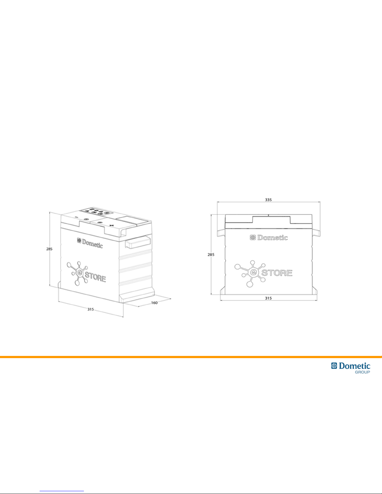
Dimensions
* ± 1mm
3
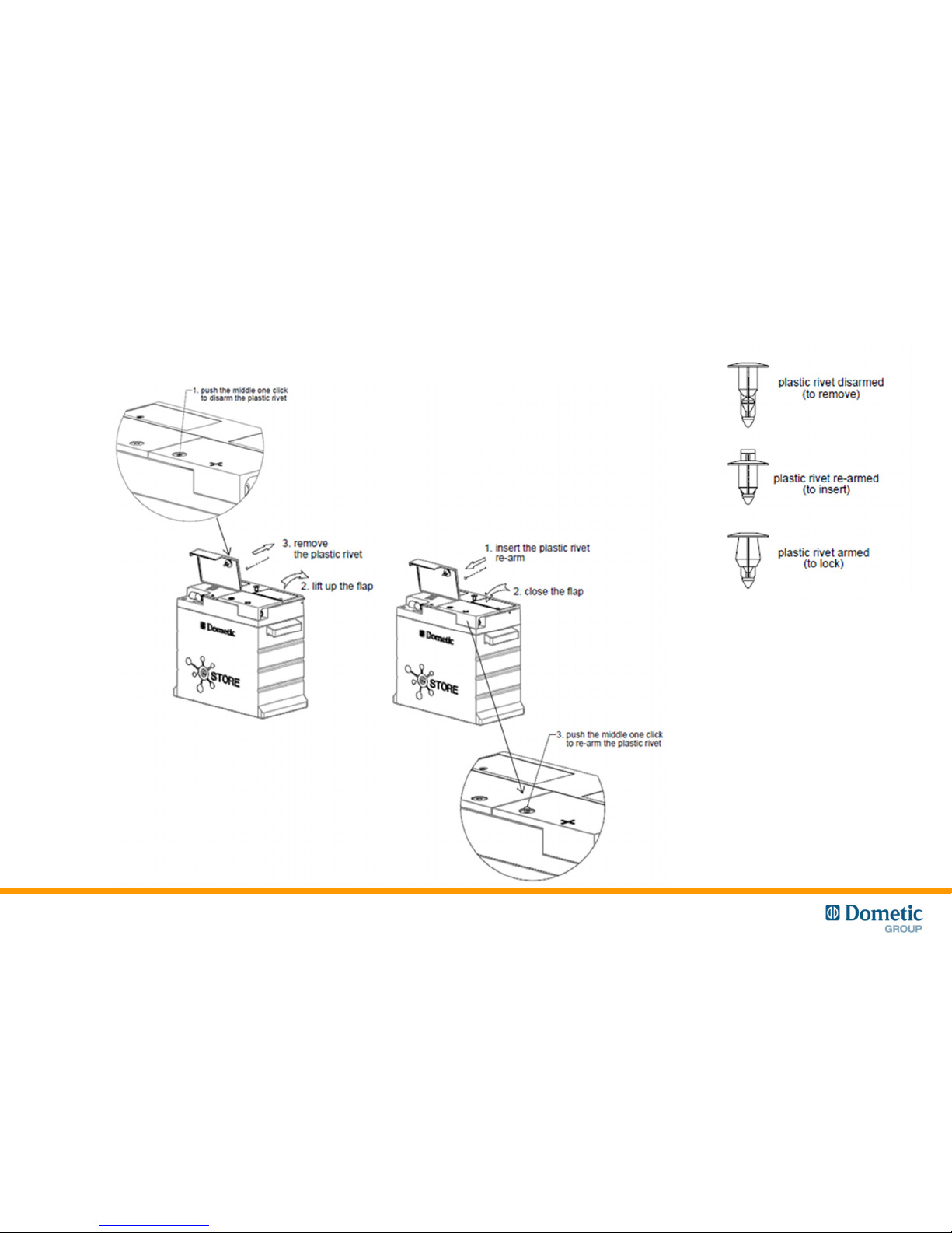
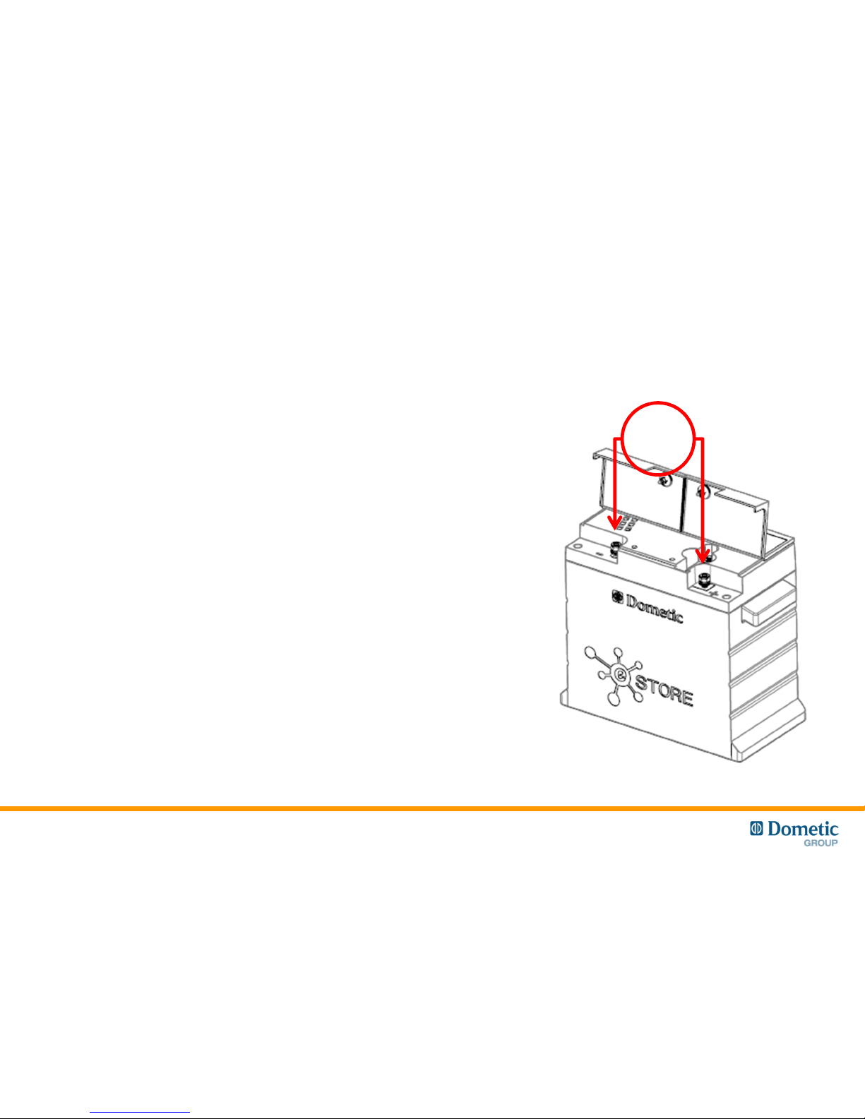
Terminal Cover
4
Block here!
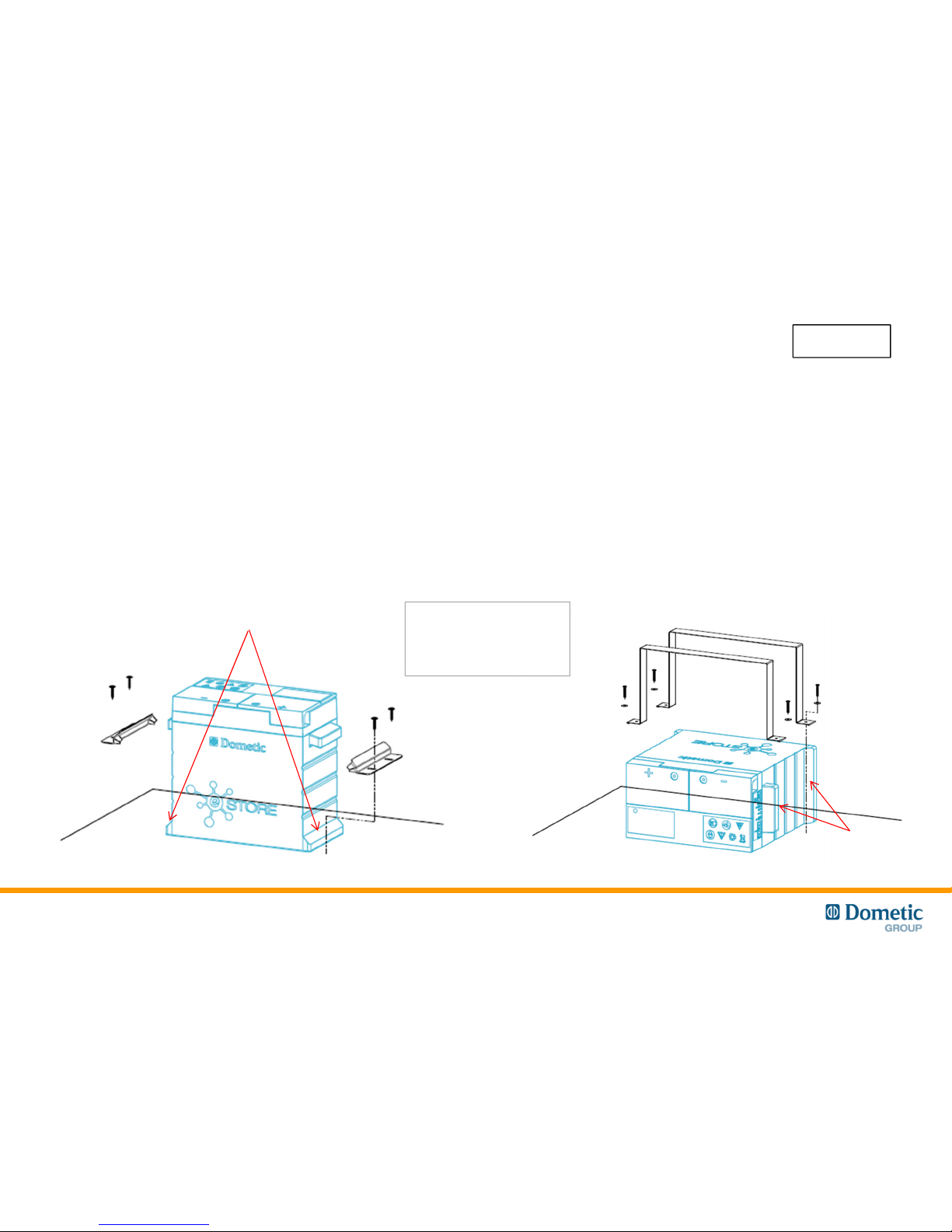
Mounting examples
Vertical Mounting
• Use the mounting feet to secure the eStore
• DO NOT use straps to hold down the
battery as they may damage the eStore.
• Maintain at least 1cm between eStore
packs in multiple installations
5
New
Horizontal Mounting
• Use bands or straps, placed between the
inside of the handles and mounting feet, to
secure the eStore
• DO NOT use straps on any part of the plastic
cover as they may damage the eStore.
• Do not stack the eStores
* Comparable performance when tested for vibration, cycle life and charge / discharge performance.
Reports available on request.
Block here!
Brackets and straps are
shown for indication
purposes only and are
not supplied by Dometic!
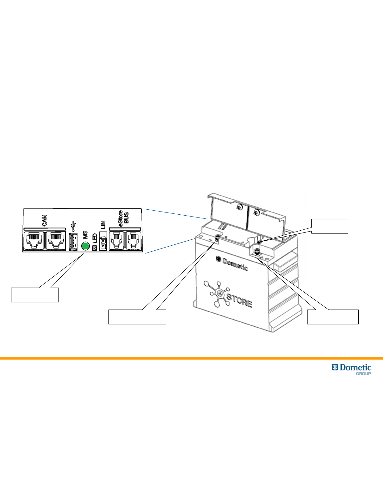
Fuse
Negative terminal Positive terminal
Interfaces
Main Switch
Command
6
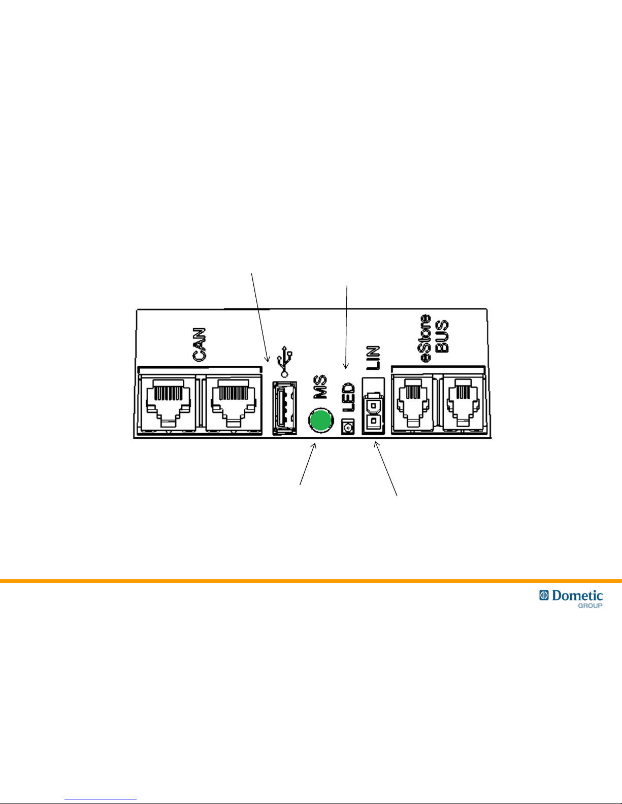
Interfaces II
eCore to eStore
(RJ45)
eStore to eStore
(RJ11)
USB for
eStore set up
Main Switch
Command
LIN /CIB Bus
Molex Minfit
Upper pin (2) – ground
Lower pin (1) – signal
3 Colour
Status LED
7
• All eStores are equipped with a Main Switch
• The Main Switch opens automatically to protect the eStore battery pack from over voltage or
under voltage and overcurrent.
• The Main Switch can also be operated manually with the Main Switch (MS) Command button
• Manual Operation
• Note: The Main Switch Command (MS command) is active only on the Master eStore
(see next slides)
Main Switch
8
Close Main Switch:
Press & hold MS Command
• “Tic” sound
• LED flashes green
Open Main Switch:
Press & hold MS Command
• “Toc” sound
• LED flashes yellow
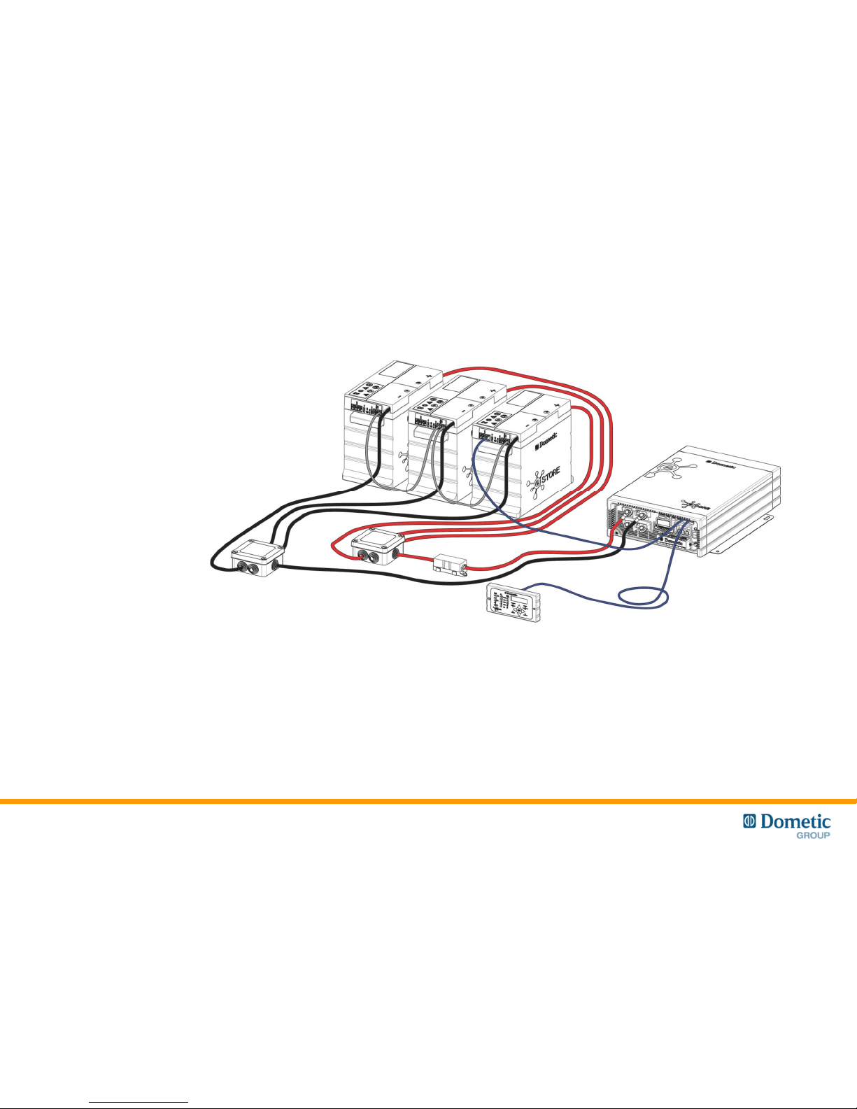
Multiple packs (eStore Bus)
9
• Up to 8 eStore can be connected in parallel, to increase total storage capacity.
• The eStore Bus allows communication between eStores. It also provides synchronous control of
the Main Switch on all eStores connected.
• The Main Switch Command of the first eStore pack (Master) controls all others.
• The first eStore pack (Master) is connected to the Dometic eCore with RJ45 CAN cable.
(connection to Dometic Weaco MCA series chargers is though the LIN BUS connection)

Master
Slave
Slave
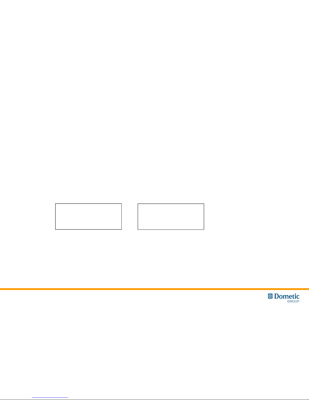
Master / Slaves
Master
• eStore with CAN connection to eCore (or Weaco LIN Control panel and charger)
• Pack Address #1 in Battery Configuration utility
Slave
• eStore with data bus connection to other eStore
• Pack Address #2…7 in Battery Configuration utility
10
12V
• eStore is delivered in Storage mode to reduce self discharge
• To wake up the eStore, apply 12V DC to terminals.
• The yellow status LED will begin to flash yellow
(indicating that Main Switch is open)
Storage Mode
11
 Loading...