

Dometic Eskimo Ice 600 Installation & Owner's Manual

Eskimo Ice 600
Installation/Owners Manual
Self Contained Ice Making System
Revised: 5-5-06
L-2448A

TABLE OF CONTENTS
Installation Instructions
Installation Drawings
Start-up Procedure
Trouble Shooting
Maintenance
Wiring Diagrams
Parts Breakdown
Technical Support Information
Copyright 2005 Dometic Environmental Corporation, All Rights Reserved - Every precaution has been taken in the preparation of this manual to insure its accuracy. However, Dometic Environmental
Corporation assumes no responsibility for errors or omissions. Neither is any liability assumed for damages resulting from the use of this product and information contained herein.
L-2448A
2
YY
Y
YY
English

Installation Instructions for E.I. 600
Read all instructions before starting the installation
Locating ice machine
Locate flat level platform for E.I.600. Do not place where salt spray is present or corrosion problems
will result. Locate so that electrical control panel (with off/on switch) faces out for easy access.
Test routing of 1 1/4" ID delivery hose (delivery elbow on unit will swivel to face different
directions). Check routing of 1/2" I.D. raw water hose which connects to hose barb facing
downward at top rear of ice machine (marked “water inlet”). Check 5/8" I.D. hose for raw water
discharge which connects to hose barb on top of unit (marked “water outlet”). Check 1/4" I.D. fresh
water hose which connects to 1/4" male flare fitting on back of machine. Check access to high and
low refrigerant schrader valves on top right and front right of ice machine.
If routing of all hoses is clear, fasten unit down with four 1/4" lag bolts or 1/4" bolts and nuts.
Routing ice delivery hose
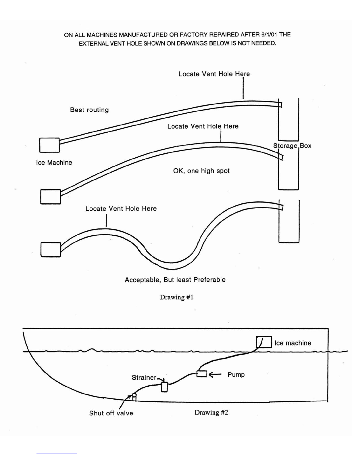
Route the hose so that it travels up hill until it reaches the ice storage box. Route with as few bends
as possible and no sharp or 180 degree bends. Total length should be less than 30 feet. If hose runs
uphill and down with only one high spot, this will be OK. However, the hose should not have low
spots which would trap water. (See Drawing #1.) Do not bend hose with bend radius of less than
12”. Route hose into side of the ice storage box so that it is as high as possible, and centered on side
of box. This is done to maximize the amount of ice that can be piled up before it reaches the sensor
and delivery hose. Note that the ice does not level itself and will form a broad pile as it falls out of
the hose. It is desirable to have the ice storage box as deep (tall) as possible for maximum delivery of
ice.
It is not necessary to cover the delivery hose with insulation, but insulation is recommended in order
to reduce sweating of hose from condensation. The hose can be covered before installing, after, or
during installation. The insulation provided has a pre-glued seam. After placing the insulation around
hose pull off the two Mylar release liners and then press the two edges together. The disadvantage of
installing the insulation before installing the hose is that care must be taken not to tear up insulation
while working the hose into position. Since the pre-glued seam may soften and come apart with heat
and time, it is recommended that the seam and end joints be covered with white duct tape. Strap hose
securely, keeping mind that it will be heavier when filled with ice. Be careful not to crush or kink
the hose because any restriction will prevent free flow of ice.
IMPORTANT NOTE: Think of ice moving through the hose as a semi-solid that will not push past
any restrictions placed inside of the hose. Example of installations that will not work: ice hose can
not be pushed over a pipe or over a thru-hull fitting. Do not use hose other than factory ice hose.

Ice delivery hose installation detail
We are using a thru-hull fitting for delivery of ice into storage box. Drill hole for thru-hull fitting in
storage box. Make this hole 2 3/8" in diameter. (See drawing #6.) Also see yellow template in
temperature control box. (See drawings #4, 5 and 9 also). Install thru-hull fitting in this hole from
inside the box. If thru-hull will need to be removed in order to lift out the box, do not install with
caulking. Otherwise caulk in the fitting. (See drawing #9 for optional attachment of ice hose to fish
boxes which will be lifted out.) Slide ice hose into the thru-hull up to internal shoulder and lightly
tighten hose clamp on outside of fitting to secure the ice hose. Over tightening of clamp will cause
later collapse of the hose. ON ALL MACHINES MANUFACTURED OR FACTORY REPAIRED
AFTER 6/1/01 THE EXTERNAL VENT HOLE IS NOT NEEDED. On these new machines the
following steps are not needed. After ice delivery hose is completely installed, locate highest point of
hose within ten feet of ice machine. Cut out a one square inch of insulation on top of hose. Drill a
1/8" hole in ice delivery hose, drill only through top of hose in center of removed insulation area.
This hole must be located before the first low spot in the hose. (Example if first low spot in hose is at
two feet then the hole must be in the first foot.) Under some circumstances a slight amount of water
may come out this hole. Do not locate this vent hole over any equipment that may be damaged by
dripping water. If stainless spout is turned downward and ice hose is routed out the side of the frame
rather than in an upward direction it will be necessary to locate a vent hole at the top of the stainless
spout near where it meets the fastening plate. See drawing #7.
Raw water pump plumbing hook up
Pick up water from 1/2" or larger sea cock, run through sea strainer, and then run to pump. Pump
must be located below water line since it is not self priming. Run hose uphill from sea cock to pump
and uphill from pump to ice machine. If the hoses are run correctly all the water will drain out of the
hoses when the boat is hauled out of the water. (See drawing #2) If hoses are not run correctly,
continual problems with the pump becoming air locked will occur. When fastening 1/2” I. D. hose
to raw water pump, slide hose directly over threaded discharge nipple and clamp. Do not thread
fitting onto discharge nipple because it will cause the nipple on pump housing to break at the threads.
See separate instruction sheet about installing and positioning raw water pump. Pay particular
attention to locating with water outlet facing up.
Run 5/8" I.D. hose from discharge barb on unit to 1/2" or larger overboard thru-hull fitting.
Main power electrical hook up
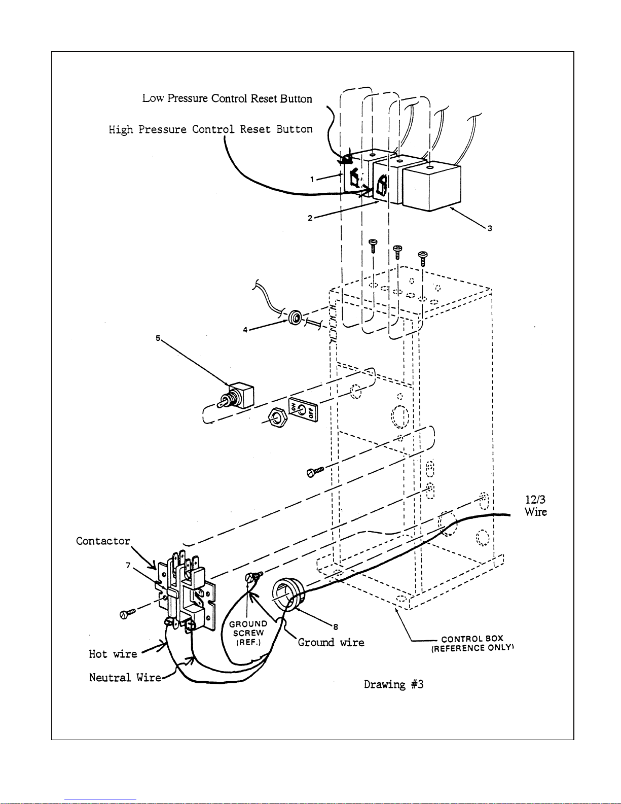
Run 12/3 wire from 20 amp. circuit breaker to electric control box. Run wire into small grommeted
hole in back of electric box. Attach power wires to lower screws of contactor. Use spade terminals
under screws not .250 push on terminals (fasten hot lead to left screw on 115V models). Attach
ground wire to green screw in lower back of electric box. ( see drawing #3)
Raw water pump electrical hook up
The voltage for the raw water pump supplied with the Eskimo Ice machine should match the input
voltage marked on the front I. D. label of the ice machine. All that is necessary to wire the pump is to

install the male plug to the pump wire (green wire to green screw, black to brass, and white to silver,
115V). (green to green, black and white to brass for 230VInsert male plug on pump into female on
the pigtail attached to the machine, if desired pigtail and plugs can be eliminated, and pump wires
directly into electrical control box. Matching crimp terminals are provided for this purpose. They are
located in the zip lock bag with the hose clamp.
Fresh water plumbing hook up
Tap into ship's fresh water line and add a shut off valve. Run 1/4" I.D. water hose from valve to 1/4"
male flare fitting on back of machine (marked “fresh water inlet”). 90 degree fitting provided in bag
with terminals and hose clamp.

Thermostat installation and wiring of the E.I. 600
Installation of temperature control
This ice machine uses a Ranco ETC control. We recommend mounting in an accessible location
near the unit. Since this control has an LED indictor and switches which can be useful in
monitoring and testing the ice machine, a convenient location is preferred. A clean dry location
in the engine room is also acceptable, perhaps on a bulkhead near the ice machine.
See trouble shooting item #8.
Installation of the sensor
Locate the sensor just below the ice delivery hose and slightly to the left or right, approximately one
inch below the thru-hull and one inch off the center line. (This is to avoid having water and ice
hitting sensor on the way into the box.) See drawings #4 and #5. Drill a 3/8” hole in storage box to
pass sensor through. See full size yellow template in SP-32 box. Fasten sensor to inside of box with
stainless steel cover provided. This will cover the whole, upper third of sensor and wires. Fasten
cover down with two screws. If sensor will not have to be removed in lifting out storage box, it may
be caulked in place. See drawings #4, 5, and 6.
Temperature control wiring
See wiring diagram G901001 included in this manual.
Wear prevention check
Check all metal tubing to see that there is no contact. Contact might cause excessive wear when
machine is operating, thus causing a refrigerant leak. Tubes can be tapped to listen for contact. Pay
particular attention to tubes from pressure controls in electrical box.

Corrosion control
Covering all electrical components and wiring connections with a corrosion product will help reduce
corrosion problems years into the future. The complete ice machine can be coated with a spray like
Corrosion Block.
Winterizing-warning
See note on below freezing temperatures in trouble shooting section #11.
Warranty card
Please fill out upper portion of warranty card, affix stamp and mail back promptly. This is the
responsibility of the installing company.
Revised: 4/26/94, 5/30/94, 7/22/94, 4/1/95, 7/5/95, 11/23/96,7/97,12/99,12/01,1/02,7/03
 Loading...