

Dometic Eskimo Cup Installation & Operation Manual
L-3423 - Rev 20150515 - P/N 337817
1
4
Eskimo Cup
Installation & Operation
Manual
OVERVIEW
The Dometic Eskimo Cup is a thermoelectric
refrigerated cup holder. It is designed to
accommodate mounting into surfaces of various
thicknesses.
A polished marine-quality 316 stainless-steel trim
ring finishes the surface installation and is
accented with two blue LED interior lights.
S
AFETY PRECAUTIONS
INSTALLATION PROCEDURE
(For a quick video overview, see “How to Install the Dometic Eskimo Cup” on YouTube.com)
Choosing the Location
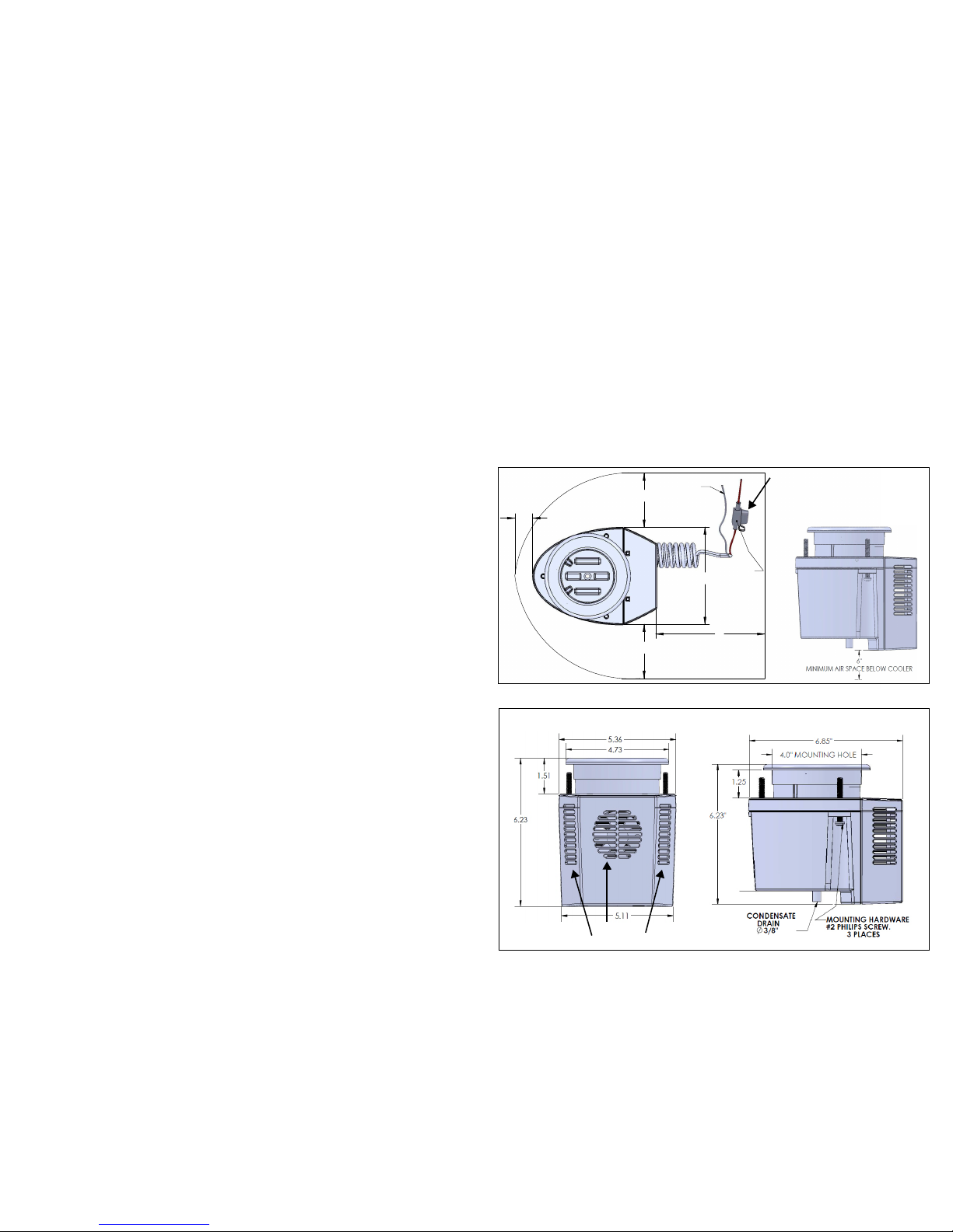
Choose an installation location that does not interfere with existing below-deck objects and
has enough ventilation below the surface to help dissipate the heat of 150 BTUs generated
by the thermoelectric process. Allow 6 in (15 cm) of space on all sides of the unit. See
Figures 1 and 2. Note: If space underneath does not have proper ventilation, an
optional vent or power vent might have to be installed to remove the built-up heat or
unit will not cool your beverage properly.
Do NOT locate in area where under-mounted portion of unit will receive frequent seawater
exposure or deck wash down.
See Figure 2 for detailed dimensions. For optimum performance, mount the Eskimo Cup
with the LED lights (rounded end) toward the bow or uphill to allow gravity to pull the
beverage toward the coldest side of the cooler bore. See Figure 3.
CAUTION
Do not over tighten mounting screws. Do not use a power driver. Tighten by hand
ONLY!
To mount the unit, tighten the 3 mounting screws evenly until they contact the
underside of the mounting surface. For hard surfaces, tighten the unit down evenly
by tightening each of the 3 screws 1 additional full revolution after surface contact.
For soft surfaces, tighten each of the 3 screws 2 additional full revolutions after
surface contact.
CAUTION
• Do not use an abrasive cleaner to clean the stainless-steel trim ring. It will
scratch the surface.
• Do not use an abrasive cleaner to clean the cooler bore. It has an anti-stick
coating and it will be damaged.
CAUTION
Eskimo Cup may freeze beverages in cold ambient temperatures.
CAUTION
Ventilation is required to dissipate heat, otherwise poor performance and
overheating may occur..
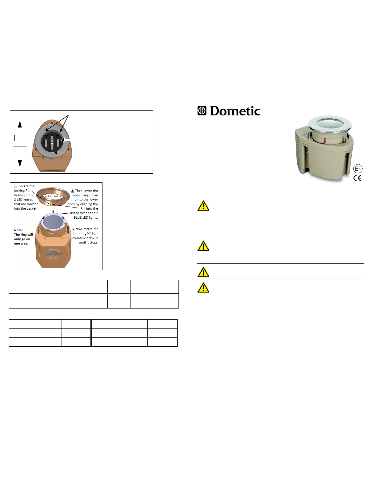
Figure 3: Optimum Positioning
Figure 4: Upper Trim Ring Installation Procedure
SPECIFICATIONS
PART NUMBERS
Amps Power Dimensions
H x W x D
Interior
Diameter
Cutout
Diameter
Power Cord
Length
Weight
3.1 12V DC 6.23 x 5.36 x 6.85 in
159 x 137 x 174 mm
2.95 in
75 mm
4.0 in
102 mm
16 in
407 mm
33.75 oz
0.96 kg
Eskimo Cup 250140101 Spare Part, Fan 250140202
Spare Part, Trim Ring 250140250 Spare Part, Can Pusher Insert 250140203
Spare Part, LED 250140201
BOW
STERN
FOR OPTIMUM COOLING HAVE BEVERAGE
CONTACT THIS SIDE OF COOLER
CAN PUSHER INSERT ONLY FITS ONE WAY, WITH THE
2 PUSHERS ON THE SAME SIDE AS THE 2 LEDs
CAN PUSHER INSERT
USAGE
This appliance can be used by
children aged from 8 years and
above and persons with reduced
physical, sensory or mental
capabilities or lack of experience
and knowledge if they have been
given supervision or instruction
concerning use of the appliance
in a safe way and understand the
hazards involved.
Children shall not play with the
appliance. Cleaning and user
maintenance shall not be made
by children without supervision.
COPYRIGHT © 2014-2015 Dometic Corporation. All Rights Reserved.
No part of this publication may be reproduced, tra nslated, stored in a retrieval system, or t ransmitted in any
form or by any means electronic, mechanical, photocopying, recording or otherwise wi thout prior written consent by Dometic Corporation. Every precauti on has been taken in the preparation of this manual to ensur e its
accuracy. However, Dometic Corporation assumes no responsibility for errors and omissio n. Neither is any liability assumed for damages resulting from the use of this product and information contai ned herein.
3
2
Installation Steps
1. Select an installation area with adequate ventilation and make sure the chosen
mounting surface is NOT thicker than 1.25 in (31.75 mm). See Figure 2. Drill a 4 in
(10.16 cm) hole in the installation surface. Seal the raw edges of the mounting
surface if applicable.
2. Detach the stainless-steel trim ring assembly from the Eskimo Cup by rotating the
ring clockwise then lift it off.
3. From beneath the installation surface, slide the Eskimo Cup upward through the
drilled hole and reattach the stainless-steel trim ring assembly by aligning the ring
pins to the entry slots, then turn the ring counter-clockwise ¾ in (19 mm). It only
fits one way. See Figure 4. Have the rounded end aimed at the bow. See Figure 3.
4. DO NOT USE POWER TOOLS! HAND-TIGHTEN ONLY! OVERTIGHTENING
WILL CAUSE DAMAGE TO THE UPPER TRIM RING LOCKING PINS. Tighten
the 3 support screws until they make contact with the underside of the mounting
surface. For hard surfaces such as solid fiberglass and metal, tighten the unit
down evenly by tightening each of the 3 screws 1 full revolution after surface
contact. For soft surfaces such as marine plywood, tighten each of the 3 screws 2
full revolutions after surface contact. DO NOT OVERTIGHTEN.
5. Connect a 3/8-in (10 mm) ID drainage hose to the drain tube fitting on the bottom
of the unit and route the output sloping downward to an appropriate drainage
location onboard.
6. Make sure the Can Pusher Insert is properly aligned in bottom of Eskimo Cup.
See Figure 3.
Electrical Connections (12 Volt DC Only)
1. Locate (or install) an auxiliary 12V DC power switch (not included) that will be
used for the Eskimo Cup. Typically this will be on a fused branch circuit attached
to the house battery (NOT the engine battery). Note: Control of Eskimo Cup(s) can
be managed with a single switch or set up with zone switching.
2. With the power off, attach the wires of the Eskimo Cup to the wiring of that switch;
the red wire is positive and the black wire is negative. Each unit has a 5 amp fuse
built into its wiring which should be positioned in an accessible location.
3. Power on the switch and verify the blue lights inside the Eskimo Cup are lit.
NOTE: Low-voltage cut off is at 10.5 volts DC to avoid a dead battery.
O
PERATION
1. Power on the switch that controls the Eskimo Cup(s).
2. Allow 2 to 3 minutes for the Eskimo Cup to chill.
3. Between sips, store your can, bottle, or any appropriately sized beverage
container in the Eskimo Cup and enjoy a drink that stays cold while you drink it.
4. For optimum performance make sure the Can Pusher Insert is aligned correctly.
See Figure 3.
T
ROUBLESHOOTING IF UNIT DOES NOT COOL WELL
Performance of unit is directly related to temperature of air at fan inlet. See Figure 2.
• If the blue LED lights are on when switch is on, then:
• Make sure beverage container is in contact with optimum area of cooler. See
Figure 3.
• Check for proper ventilation around the unit. Poor ventilation will cause poor
cooling capacity. See Figure 1.
• Make sure all electrical connections are tight. Loose connections cause high
resistance and poor performance.
• Is cooling fan running? If clogged with debris, wipe or brush fan inlet to clean. Do
not spray with water. See Figure 2.
• If the blue LED lights are NOT on when switch is on, then:
• Check for blown fuse on unit, on house battery, or an open circuit breaker.
• Check for power at unit.
• Make sure all electrical connections are tight.
• Unit’s high-heat cut off is at 150°F (65°C) and if reached, unit will shut down. This
is usually caused by lack of air flow or high ambient temperature.
• Verify polarity of DC voltage: Positive to positive and negative to negative.
• If 12V DC power is available and unit is not working, unit needs to be replaced.
W
ARRANTY
One year parts only from time of sale or ownership of boat. 24/7 Tech Support for USA &
Canada: 8 AM to 5 PM ET - 800-542-2477; After hours & weekends - 888-440-4494.
FIGURES
Figure 1: Ventilation Space Required for Mounting Eskimo Cup
Figure 2: Dimensions & Key Components of Eskimo Cup (Back & Side views)
$03)86(
&25'
MOUNT FUSE IN AN ACCESSIBLE AREA
IF NECESSARY, REPLACE WITH AN ATC
5 AMP STANDARD BLADE AUTOMOTIVE
FUSE
Side View
AIR OUTLETS
FAN I NLET
Back View
 Loading...