

Dometic ELITE SLIDE TOPPER 86200 Series, ELITE SLIDE TOPPER Series, ELITE SLIDE TOPPER 86300 Series, ELITE SLIDE TOPPER 86196 Series, ELITE SLIDE TOPPER 86202 Series Installation & Operating Instructions Manual
Page 1
RECORD THIS INFORMATION FOR FUTURE
REFERENCE:
FRTA Model Number
FRTA Serial Number
Hardware Model Number
Hardware Serial Number
Date Purchased
Retailer / Qualied Installer
ELITE SLIDE TOPPER
SLIDE OUT ROOM AWNING
WITH FULL COVER
86196(XX).(XXX)-(X)
86200(XX).(XXX)-(X)
86202(XX).(XXX)-(X)
86300(XX).(XXX)-(X)
INSTRUCTIONS
INSTALLATION & OPERATING
REVISION B
Form No. 3308250.020 09/16
(French 33108310.022_B)
©2016 Dometic Corporation
LaGrange, IN 46761
Read these instructions carefully. These
instructions MUST stay with this product.
USA
SERVICE OFFICE
Dometic Corporation
1120 North Main Street
Elkhart, IN 46514
CANADA
Dometic Corporation
46 Zatonski, Unit 3
Brantford, ON N3T 5L8
CANADA
SERVICE CENTER &
DEALER LOCATIONS
Please Visit:
www.eDometic.com
Page 2

INTRODUCTION
This Slide Topper™ awning (hereinafter referred to as “Slide Topper,” “awning,” or “product”) is intended for use on Recreational Vehicles (RVs). It is designed to protect the top of an RV’s slide out room from weather and debris. It is not waterproof;
some drips, condensation, or windblown precipitation may enter under the canopy. Use these instructions to ensure correct
installation, function, and operation of product.
Dometic Corporation reserves the right to modify appearances and specications without notice.
TABLE OF CONTENTS
INTRODUCTION .................................................................................................................................................................... 2
DOCUMENT SYMBOLS ........................................................................................................................................................2
IMPORTANT SAFETY INSTRUCTIONS ................................................................................................................................3
A. Recognize Safety Information ...................................................................................................................................3
B. Understand Signal Words ..........................................................................................................................................3
C. Supplemental Directives ............................................................................................................................................3
D. General Safety Messages .........................................................................................................................................3
GENERAL INFORMATION .....................................................................................................................................................4
A. Bracket Options ......................................................................................................................................................... 4
B. Optional Components & Kits .....................................................................................................................................4
C. Important Hardware Information ................................................................................................................................4
SPECIFICATIONS .................................................................................................................................................................. 4
A. Slide Out Room And Slide Topper Dimensions .........................................................................................................4
B. Mounting Bracket Selection ....................................................................................................................................... 6
C. Mounting Bracket Spacer (Optional) .........................................................................................................................7
INSTALLATION ......................................................................................................................................................................8
A. Prepare Slide Topper ................................................................................................................................................. 8
B. Installation Instructions .............................................................................................................................................. 8
OPERATION ......................................................................................................................................................................... 12
GENERAL USE AND CARE .................................................................................................................................................13
A. Precautions .............................................................................................................................................................. 13
B. Hardware Maintenance ...........................................................................................................................................13
C. Fabric Maintenance .................................................................................................................................................13
D. When To Get More Help ..........................................................................................................................................13
DOCUMENT SYMBOLS
Indicates additional information that is NOT related
to physical injury.
Indicates step-by-step instructions.
2
Page 3

IMPORTANT SAFETY INSTRUCTIONS
This manual has safety information and instructions to help
you eliminate or reduce the risk of accidents and injuries.
A. Recognize Safety Information
This is the safety alert symbol. It is used to
alert you to potential physical injury hazards.
Obey all safety messages that follow this
symbol to avoid possible injury or death.
B. Understand Signal Words
A signal word will identify safety messages and
property damage messages, and will indicate the
degree or level of hazard seriousness.
indicates a hazardous situation that,
if NOT avoided, could result in death or serious injury.
indicates a hazardous situation that,
if NOT avoided, could result in minor or moderate
injury.
is used to address practices NOT
related to physical injury.
C. Supplemental Directives
Read and follow all safety information and
instructions to avoid possible injury or death.
Read and understand these instructions before [installing / using / servicing / performing
maintenance on] this product.
Incorrect [installation / operation / servicing /
maintaining] of this product can lead to serious injury. Follow all instructions.
The installation MUST comply with all applicable local and national codes, including
the latest edition of the following standards:
U.S.A.
● ANSI/NFPA 1192, Recreational Vehicles
Code
CANADA
● CSA Z240 RV Series, Recreational
Vehicles
D. General Safety Messages
Failure to obey the following warnings could result in death or serious injury:
● This product MUST be [installed / serviced] by a
qualied service technician.
● Do NOT modify this product in any way. Modica-
tion can be extremely hazardous.
● Do NOT add any devices or accessories to this
product except those specically authorized in
writing by Dometic Corporation.
● Frequently examine product for imbalance (un-
even t / sagging / loose parts); and signs of wear
or damage to wiring (if applicable) and other critical parts. Do NOT use product if adjustments or
repairs are necessary.
Critical parts may include awning fabric,
brackets, arm assemblies, etc.
● Do NOT allow anyone (including children) with
reduced physical, sensory or mental capabilities,
or lack of experience and knowledge to use this
product, unless they have been given supervision
or instruction (concerning use of this product) by
a person responsible for their safety.
● Do NOT allow children to play with product or with
xed controls (if applicable).
● IMPACT OR CRUSH HAZARD. NEVER leave an
open awning unattended. Keep awning stowed
(closed) when snow, heavy rain, wind, and severe
weather conditions are expected.
● FIRE HAZARD. Keep sources of heat and re
(barbecue grills, portable heater, etc.) away from
awning.
PINCH HAZARD. Maintain a hori-
zontal distance of at least 16″ between fully open
awning and any permanent object. Failure to obey
this caution could result in injury.
Do NOT face [slide out room / Slide Top-
per] toward permanent objects that may
interfere with awning operation.
3
Page 4
GENERAL INFORMATION
A. Bracket Options
One of the following Slide Topper bracket options is
required (not included):
(1) 3106992.062# 45º Wall Bracket Kit with 15″
Hex Extension
(See Note 1)
(1) 3106992.162# 45º Wall Bracket Kit with 18″
Hex Extension
(1) 3106992.262# 45º Wall Bracket Kit with 15″
Steel Hex Extension
(See Note 2)
(1) 3106992.070# 90º Wall Bracket Kit with 15″
Hex Extension
(1) 3106992.170# 90º Wall Bracket Kit with 18″
Hex Extension
(See Note 1)
(1) 3106992.270# 90º Wall Bracket Kit with 15″
Steel Hex Extension
(See Note 2)
Note 1: Use ONLY with 86(XXX)(XX).060 Models.
B. Optional Components & Kits
(1) 3107940.003 Mounting Bracket Spacer Kit
(1) 3308176.001 Edge Protector (10 Pack)
(1) 3308176.019 Edge Protector (100 Pack)
(1) 3309526.170# Cradle Kit
C. Important Hardware Information
Slide Toppers 198″ - 261″ REQUIRE the fol-
lowing options / kits:
● A bracket option that includes STEEL ex-
tensions.
● A center support for cover (included).
Slide Toppers 264″ or wider REQUIRE the
following options / kits:
● A bracket option that includes STEEL ex-
tensions.
● 3 center supports for cover (included)
Note 2: Use ONLY with 86(XXX)(XX).264 Models
and above.
SPECIFICATIONS
A. Slide Out Room And Slide Topper
Dimensions
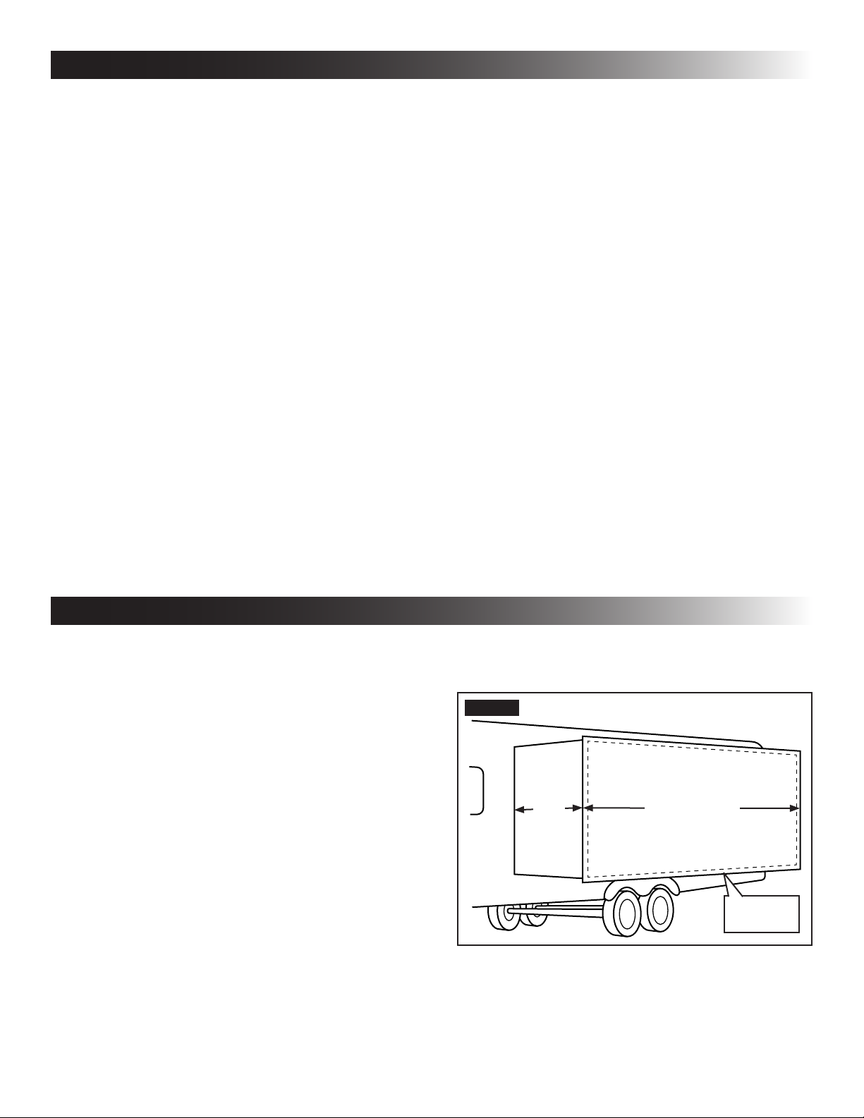
1. Full extension of slide out room MUST NOT ex-
ceed 44″. See (FIG. 1).
2. Determine Slide Topper width.
a. Measure slide out room width. See (FIG. 1).
b. Match Slide Topper fabric width (B) as close-
ly as possible to slide out room width. See
(FIG. 1) and table.
See "C. Important Hardware Information"
on page (4) regarding options / kits RE-
QUIRED for longer Slide Topper lengths.
FIG. 1
Slide Topper fabric should completely cover
slide out room. See table for selection guidance.
Slide Out
44″
Maximum
Extension
Room Width
(Including Flange)
Slide Out
Room
4
Page 5

SPECIFICATIONS
SLIDE OUT
ROOM WIDTH
50″ to 55-3/4″ SEE NOTE 1
56″ to 61-3/4″ 66″
62″ to 67-3/4″ 72″
68″ to 73-3/4″ 78″
74″ to 79-3/4″ 84″
80″ to 85-3/4″ 90″
86″ to 91-3/4″ 96″
92″ to 97-3/4″ 102″
98″ to 103-3/4″ 108″
104″ to 109-3/4″ 114″
110″ to 115-3/4″ 120″
116″ to 121-3/4″ 126″
122″ to 127-3/4″ 132″
128″ to 133-3/4″ 138″
134″ to 139-3/4″ 144″
140″ to 145-3/4″ 150″
146″ to 151-3/4″ 156″
152″ to 157-3/4″ 162″
158″ to 163-3/4″ 168″
164″ to 169-3/4″ 174″
170″ to 175-3/4″ 180″
176″ to 181-3/4″ 186″
182″ to 187-3/4″ 192″
188″ to 193-3/4″ 198″
194″ to 199-3/4″ 204″
200″ to 205-3/4″ 210″
206″ to 211-3/4″ 216″
212″ to 217-3/4″ 222″
218″ to 223-3/4″ 228″
224″ to 229-3/4″ 234″
230″ to 235-3/4″ 240″
236″ to 241-3/4″ 246″
242″ to 247-3/4″ 252″
248″ to 253-3/4″ 258″
254″ to 259-3/4″ 264″
260″ to 265-3/4″ 270″
266″ to 271-3/4″ 276″
272″ to 277-3/4″ 282″
278″ to 283-3/4″ 288″
284″ to 289-3/4″ 294″
290″ to 295-3/4″ 300″
296″ to 301-3/4″ 306″
302″ to 307-3/4″ 312″
RECOMMENDED
AWNING LENGTH
SLIDE OUT
ROOM WIDTH
308″ to 313-3/4″ 318″
314″ to 319-3/4″ 324″
320″ to 325-3/4″ 330″
Note 1: Use ONLY with 86(XXX)(XX).060 Models.
Note 2: Use ONLY with 86(XXX)(XX).264 Models
and above.
5
RECOMMENDED
AWNING LENGTH
Page 6

SPECIFICATIONS
B. Mounting Bracket Selection
1. Determine mounting bracket type. See (FIG. 2) & (FIG. 3). See available bracket kits under "A. Bracket Options"
on page (4).
Mounting brackets may be installed on slide out room ange ONLY if it provides solid structural support.
FIG. 2
Awning
Rail
1-1/4″
Slide Out Room Flange
(With Edge Protector)
6″ Min.
7″ Max.
5 1/4″ Max.
Slide Out Room Flange
Mounting Bracket
Mounting Bracket Kit
3106992.X62#
Extension
Awning Rail
Mounting Bracket
FIG. 3
Slide Out
Projection
(Closed)
1/4″ Min.
1″ Max.
Awning
Rail
1-1/4″
Slide Out Room Flange
(With Edge Protector)
6″ Min.
7″ Max.
5 1/4″ Max.
Slide Out Room Flange
Mounting Bracket
Mounting Bracket Kit
3106992.X70#
Extension
Awning Rail
Mounting Bracket
6
Page 7

SPECIFICATIONS
2. Determine mounting bracket location relating
to awning rail and slide out room ange. See
(FIG. 2), (FIG. 3), (FIG. 4) & (FIG. 5).
If Slide out room has extra anges, it may
be necessary to install mounting brackets
directly on ange, but ONLY if it provides
solid structural support.
To help accommodate water and debris runoff, awning fabric should have as
steep a pitch (slope) as feasible without
exceeding the maximum distance shown
between awning rail and mounting bracket. Exceeding the maximum distance will
expose awning fabric to catch wind (causing fabric to billow or tear).
FIG. 4
Mounting Bracket Shown
In Typical Position
(Below Flange)
C. Mounting Bracket Spacer (Optional)
If slide out room ange has special features (large
curve, recessed into RV wall, etc.) that will interfere
with normal operation of Slide Topper, a mounting bracket spacer (NOT INCLUDED) must be installed. See (FIG. 6) & (FIG. 7).
Mounting bracket spacer thickness may
vary depending on spacer kit requirements.
FIG. 6
Large Curve
In Flange
Mounting
Bracket Spacer
FIG. 5
Mounting Bracket Shown
Directly On Flange
FIG. 7
3/4″ (Kit May Vary)
RV Wall
Recessed
Flange
Mounting
Bracket Spacer
3/4″ (Kit May Vary)
7
Page 8

INSTALLATION
A. Prepare Slide Topper
The Slide Topper requires minor preparation before
installing on RV.
1. Carefully lay fabric roller tube assembly (FRTA)
on a clean, well padded “V” trough (or other well
protected surface) to prevent fabric damage.
2. In one hand, grasp cover at bottom edge near
end of one torsion bracket and pry cover up
approximately 1-2 inches while holding torsion
bracket with other hand. Repeat process for opposite side and continue to lift until cover can
be fully removed. See (FIG. 8). Lay cover aside.
FIG. 8
Hold
Down
Here
Cover
Grasp Here
& Pull Up
Hold
Down
Here
B. Installation Instructions
1. Determine awning rail location relating to mount-
ing bracket & slide out room ange. See (FIG. 2)
& (FIG. 3).
2. Remove any ashing or drip shields that will interfere with the Slide Topper.
The Slide Topper may be assembled and
held in place to check for interference.
3. Install awning rail on a at surface
(with solid structural backing), straight (without
curves), and parallel to RV oor to ensure correct function and appearance.
ALWAYS seal against weather and moisture
where components enter RV’s [walls / roof /
oor]. Otherwise, water leakage could occur.
Apply sealant to back edge of awning rail, and to
the #8-18 X 1″ screws. Then place and tighten
screws through awning rail and into solid structure of RV.
Some models do NOT include rail and
screws. See "B. Optional Components &
Kits" on page (4) to order.
4. Make sure awning rail is parallel
to RV oor, and is NOT warped or curved before
installing awning fabric. If awning rail is NOT
straight, awning fabric may wrinkle or stretch.
Select the desired awning rail end (on RV) into
which the awning fabric will be inserted. Widen
that end of the rail with a at screwdriver, and le
off any sharp edges. See (FIG. 9).
3. Carefully roll slide topper over and remove all
mounting hardware if included with slide topper.
IMPACT OR PINCH HAZARD.
Do NOT remove cotter pin from torsion rod (at
end cap) until awning fabric is attached to awning rail, torsion rod is secured to assembled
hardware (arm, extension rod, mounting bracket), and hardware is secured to slide out room.
Otherwise, rapid casting spin off will occur.
Spring tension will attempt to spin the hardware
and/or fabric roller tube quickly and unexpectedly. Failure to obey this warning could result in
death or serious injury.
FIG. 9
Before After
5. Install one (1) hex extension rod into torsion
bracket hex slot. Press into hex slot until hex extension rod bottoms out. See (FIG. 10). (Some
applications may have one hex extension bar
already secured to torsion bracket when received.)
8
Page 9

INSTALLATION
FIG. 10
#10-32 X 1/2″ Quadrex Trilob Screw
10. Slide the pre-mounted hex extension rod into
one of the previously mounted wall mounting
brackets on slide out room as the fabric is installed into awning rail. See (FIG. 12)
Torsion
Bracket
Hex Extension Rod
6. Locate and install slide topper wall mounting
brackets on the slide out room wall with (10)
#10-12 X 1″ PHCR screws. Position bracket as
shown in (FIG. 2) & (FIG. 3). Install “Z” brackets
at top of bracket as shown. See (FIG. 11). Pre-
drill hole with 1/8″ bit drill bit and install screws.
FIG. 11
45º Bracket
0.75″ Min. Clearance From
Inside Edge of Room Flange
90º Bracket
FIG. 12
+
Awning Rail
+
Wall Mounting Bracket
11. While one person guides the awning fabric into
awning rail (a stepladder may be necessary),
carefully move (slide) the Slide Topper until fabric is in desired position. See (FIG. 13).
At least one other person is required to help
hold and control Slide Topper (in place)
until mounting brackets are installed on
RV, and FRTA (with arms and extensions)
is installed on mounting brackets.
"Z" Bracket
#10-12 X 1″ Screws
7. Unfurl ONE wrap of fabric from the FRTA.
Do NOT unfurl more than 1 revolution of fabric, as this could cause issues with
awning [closing / opening] correctly.
Unfurl awning fabric 1 revolution before inserting
fabric (with awning roller cover, if equipped) into
awning rail.
Unfurling 1 revolution allows enough
space between wall and awning hardware
to guide awning fabric into awning rail.
8. Move Slide Topper and remaining hex extension
rod to RV.
9. With the slide out room completely closed, carefully lift Slide Topper to prepared awning rail end
(above top of slide out).
FIG. 13
Awning Rail
Awning Fabric
12. Install the second hex extension rod through the
other wall bracket and into the torsion bracket
hex slot. Press into hex slot until hex extension
rod bottoms out. See (FIG. 14).
Do NOT secure either hex extension rod
to wall mounting brackets at this time.
9
Page 10

INSTALLATION
FIG. 14
FIG. 15
Torsion
Bracket
Awning Rail
+
Wall Mounting Bracket
#10-32 X 1/2″ Quadrex Trilob Screw
Wall Mounting
Bracket
Hex Extension Rod
FIG. 16
Contact
Point
+
#10-32
X 1/2″
Self
Tapping
Screw
+
#10-16 X .63″ PHCR Screws
Cover
Cotter Pin
Wall
Mounting
Bracket
Contact
Point
+
#10-32
X 1/2″
Self
Tapping
Screw
15. Move one torsion bracket until cover touches
both contact points. See (FIG. 16).
16. Remove cotter pin by pulling it straight out. See
(FIG. 16).
17. Secure hex extension rod to wall mounting
bracket using (4) #10-16 X .63″ PHCR SS self
drilling screws. Predrill hex rod through-holes
(11/64″) in torsion bracket. Secure torsion brackets to hex rod using #10-32 X 1/2″ Quadrex Tri-
lob screws.
Take care NOT to change torsion bracket
position during this step. Torsion bracket
MUST have back edge parallel to RV wall
before, during, and after this step. See
(FIG. 2), (FIG. 3), (FIG. 17) & (FIG. 16).
13. Position slide topper so that it is centered between wall mounting brackets.
14. Retrieve the cover and slide the center mounting
bracket to center of cover. See (FIG. 21). Place
it upside down on top of the torsion brackets allowing it to rest on inside of torsion brackets.
See (FIG. 16).
Care MUST be taken to make sure cover does NOT inadvertently fall of torsion
brackets while performing next step.
FIG. 17
Wall
Mounting
Bracket
Hex Extension Rod
#10-16 X .63″
PHCR SS Screws
18. Roll cover downward and push it straight onto
torsion brackets until it “snaps” into place. See
(FIG. 18).
PINCH HAZARD. Keep ngers
and hands away from pinch points. Failure to
obey this caution could result in injury.
10
Page 11

INSTALLATION
FIG. 18
Pinch
Point
Cover
Pinch
Point
III. Pull to stretch opposite edge of awning
fabric approximately 3/4″, and secure with
#6 X 7/16″ TEK screw through awning rail
(approximately 2″ from fabric edge).
FIG. 19
2″
22. Adjust cover from side to side if necessary. Center the cover between torsion brackets.
23. Secure cover to torsion brackets using (1) 1/4″-
20 X 5/8″ pan head bolt in each corner of cover.
#6 X 7/16″
TEK Screw
Awning Rail
Fabric Edge
19. Cotter pins MUST be removed
from Slide Topper end caps BEFORE operating
slide out room. Otherwise, damage to the Slide
Topper and/or slide out room will occur.
Verify cotter pins have been removed from both
end caps. See (FIG. 16).
20. Open and close slide out room four or ve times
to allow natural self adjustment of awning fabric.
See instructions provided with the RV
slide out room.
21. Verify alignment of awning fabric:
a. If there is a misalignment, adjust the arm ex-
tensions by loosening the clamping screws
and move the extension accordingly. (Retighten screws.)
b. Cycle slide out room again to check align-
ment.
c. Once satised with alignment, secure fabric
as described:
I. Mark location of awning fabric edges on
awning rail.
II. Pull one edge of awning fabric approxi-
mately 1/4″ beyond marked position, and
secure with #6 X 7/16″ TEK screw through
awning rail (approximately 2″ from fabric
edge). See (FIG. 19).
FIG. 20
24. Attach center support bracket to slide out room
wall using (2) #10-12 X 1″ PHCR SS screws.
See (FIG. 20) & (FIG. 21).
1/4″-20 X 5/8″ Pan Head Bolt
Center Support Bracket
If 3107940.003 Spacer Kit was used to
the space the wall mounting bracket, the
center support bracket will also need to
be spaced, therefore 3308393.002 Center
Support Spacer Kit is necessary.
A Center Support Bracket without a spacer
may be secured with Oscar rivets if there
is no backing behind the outside skin of
RV.
11
Page 12

INSTALLATION
FIG. 21
Cover
#10-12 X 1″ PHCR SS Screws
ALWAYS position center support di-
rectly in middle of roller tube. Otherwise, damage to
awning could occur.
Slide Toppers 294″ and wider REQUIRE 3
Center Support Brackets. In this application
Center Support Brackets MUST be positioned at 1/4, 1/2, and 3/4 of the Slide Topper
length.
Center
Support
Bracket
Spacer
Starting at 1/4″ to 1/2″ beyond edge of slide out
room ange, press edge protector onto top edge
(of slide out room ange) until it is fully engaged
and secured in place. Repeat for other end. See
(FIG. 22).
See "B. Optional Components & Kits" on
page (4) to order Dometic edge protectors.
A Dometic edge protector may NOT be compatible with all applications. If a Dometic
edge protector cannot be used, a similar
type (compatible) edge protector MUST be
installed.
FIG. 22
Edge Protector
1/4″ - 1/2″
(Typical)
Slide Out
Room Flange
ALWAYS install edge protectors on
slide out room ange. Otherwise, damage to awning fabric could occur.
OPERATION
PINCH HAZARD. Do NOT operate [slide
out room / Slide Topper] with objects or people in its path.
Failure to obey this caution could result in injury.
Do NOT close [slide out room / Slide Top-
per] with leaves, sticks, or other debris on awning fabric.
The Slide Topper will automatically open and close as your
slide out room opens and closes. Follow all instructions
provided with the RV slide out room.
If slide out room is left open during rainy conditions,
some water may collect on Slide Topper. This will
cause water to spill over the sides as Slide Topper
rolls up (slide out room closes).
12
Page 13

GENERAL USE AND CARE
A. Precautions
Failure to obey the following notices
could damage product or property:
● Do NOT use insecticides or other sprays near aw-
ning fabric. These could cause stains, and could
adversely affect fabric’s ability to repel water.
● Do NOT expose awning to adverse environmental
conditions, corrosive agents, or other harmful
conditions.
● NEVER close awning (for storage) when wet. The
combination of moisture and dirt could result in
mildew, discoloration, and stains.
If it is necessary to roll up awning (temporarily) while it’s wet, make sure you roll
it out and let it dry (as soon as conditions
allow) before rolling it up again.
● Do NOT allow dirt, leaves, or other debris to ac-
cumulate on awning, which could cause abrasion
and stains. Mildew could grow on dirt and organic
debris causing permanent discoloration, stains,
and odors to awning fabric.
B. Hardware Maintenance
1. Do NOT use strong chemicals or
abrasives to clean parts, as their protective surfaces will be damaged.
Clean awning hardware (as needed) with a mild
surface cleaner.
2. Do NOT use silicone sprays near
labels. Otherwise, the label’s adhesive bond to
product surfaces could weaken.
Apply silicone spray lubricant as needed to keep
the fabric roller tube assembly’s moving parts
operating smoothly.
C. Fabric Maintenance
Vinyl fabric offers the advantage of durability and
water resistance.
Wrinkling is a normal characteristic of vinyl.
Wrinkling may be more noticeable when retracted, and after prolonged periods of stowage (rolled up). Leave awning open during
warm weather to minimize the wrinkling over
a period of time.
1. To clean:
a. Mix 1/4 cup dish soap and 1/4 cup bleach to
5 gallons of fresh water to use as cleaning
solution.
b. Do NOT use abrasive or cor-
rosive cleaners, mildew removers, or hard
bristle brushes on awning fabric.
Liberally drench open awning fabric with
cleaning solution.
c. Close awning, let it soak for 5 minutes, then
open awning again.
d. Remove solution COM-
PLETELY from awning fabric. Bleach will
degrade awning fabric if NOT completely
rinsed off.
Thoroughly hose off top and bottom of fabric
with clean water.
Repeat as necessary to completely remove solution.
e. NEVER close awning (for
storage) when wet. The combination of
moisture and dirt could result in mildew, discoloration, and stains.
Allow awning to dry thoroughly before stowing (rolling up).
2. To repair a pinhole, or if a spot of coating akes
off from top layer of vinyl fabric:
a. Apply a very small dab of VLP (Vinyl Liquid
Patch) on tip of cotton swab.
VLP is available from Dometic Corporation. Reference part number
3314216.000 when ordering.
b. Gently roll cotton swab around pinhole. The
VLP will melt the coating (on fabric) and that
will quickly ll in pinhole and blend with all
colored vinyls.
c. NEVER close (roll up) awning
when vinyl liquid patch is wet. Otherwise,
damage to other parts of awning fabric (melting through layers) will occur.
Allow VLP to dry thoroughly before stowing
(rolling up) awning.
D. When To Get More Help
If malfunctions occur (that cannot be corrected by
reviewing these instructions), contact a qualied
service technician.
It is normal for some drips, condensation, or
windblown precipitation to enter under the
Slide Topper awning canopy.
13
 Loading...