

Page 1
OPERATING
INSTRUCTIONS
RM2351
RM2354
RM2451
RM2454
RM2551
RM2554
DM2652
DM2662
DM2663
DM2852
DM2862
NDM1062
FIRE OR EXPLOSION HAZARD
If you smell gas:
1. Open windows.
2. Do not attempt to light appliance.
3. Do not touch electrical switches.
Failure to follow these instructions could result in re or explosion, which
could cause property damage, personal injury, or death.
4. Extinguish any open ame.
5. Shut off fuel supply.
6. Evacuate immediately and call
emergency services.
FOR YOUR SAFETY
Do not store or use gasoline or other ammable vapors and liquids in the vicinity of
this or any other appliance.
REVISION D
Form No. 3313240.016 12/17
(French 3313241.013_D)
©2017 Dometic Corporation
LaGrange, IN 46761
Improper installation, adjustment,
alteration, service or maintenance can cause
injury or property damage. Refer to this manual. For assistance or additional information
consult a qualied installer, service agency
or the gas supplier.
If the refrigerator stops cooling - or - if
it emits an ammonia smell, immediately
turn the refrigerator off and contact a
Service Center.
USA & CANADA
SERVICE OFFICE
Dometic Corporation
1120 North Main Street
Elkhart, IN 46514
SERVICE CENTER &
DEALER LOCATIONS
Please Visit:
www.dometic.com
Page 2
INTRODUCTION
Thank you for purchasing a new Dometic refrigerator. This product is a recreational vehicle refrigerator intended for the storage of fresh and frozen foods, as well as making ice.
Appearance of your product may vary from illustrations shown in this document.
Please read and be aware of possible safety hazards identied in this manual, and become familiar with the alert symbols
on the refrigerator. Read this manual carefully so that you know how to operate the refrigerator safely and correctly. Keep
this manual with the refrigerator for future reference.
CONTENTS
REFRIGERATOR OVERVIEW ........................................................................... 3
INSTRUCTIONS FOR USE .............................................................................. 6
STORAGE COMPARTMENTS ........................................................................... 9
PRODUCT CARE .................................................................................... 10
MAINTENANCE & SERVICE ........................................................................... 12
TROUBLESHOOTING ................................................................................ 14
APPENDIX A - SPARE PARTS .......................................................................... 15
APPENDIX B - REARVIEW EQUIPMENT ................................................................. 17
APPENDIX C - WIRING DIAGRAM ...................................................................... 19
APPENDIX D - CONSUMER SUPPORT .................................................................. 24
APPENDIX E - DOMETIC WARRANTY ................................................................... 25
APPENDIX F - MAINTENANCE SCHEDULE ............................................................... 26
SYMBOLS
The following symbols are used throughout this manual:
This is the safety alert symbol. It is used to alert you to personal injury hazards. Obey all safety
messages that follow this symbol to avoid possible injury or death.
WARNING indicates a hazardous situation which, if not avoided, could result in death or serious injury.
CAUTION, used with the safety alert symbol, indicates a hazardous situation which, if not avoided,
could result in minor or moderate injury.
NOTICE is used to address practices not related to personal injury.
Information
Step-by-step instructions
2
Page 3

REFRIGERATOR OVERVIEW
ABSORPTION COOLING SYSTEM
When turning on the refrigerator, you should adjust the thermostat (excludes RM2351, RM2451,
RM2551, DM2652 & DM2852 - not adjustable) to
the coldest temperature setting. The cooling cycle
may require an extended running time before cooling effect is observed.
LEVELING THE REFRIGERATOR
Leveling is one of the requirements for proper operation
with absorption refrigerators. To ensure proper leveling the
vehicle needs to be leveled so it is comfortable to live in
(no noticeable sloping of oor or walls).
Any time the vehicle is parked for several hours with the
refrigerator operating, the vehicle should be leveled to allow proper cooling.
When the vehicle is moving, the leveling is not critical, as
the rolling and pitching movement of the vehicle will pass
to either side of level, keeping the liquid ammonia from
accumulating in the evaporator tubing.
OPERATING REFRIGERATOR AT HIGH
ALTITUDE
All gas appliances experience lowered efciency (or rating) at high altitude This is a direct result of lower atmospheric pressure and oxygen levels, and is not a defect of
the refrigerator.
Reduced cooling performance and burner outage may
occur at altitudes higher than 5500 feet above sea level
(while operating on LP gas). Always operate refrigerator
on electric power at altitudes higher than 5500 feet.
WHEN THE REFRIGERATOR IS NOT
IN USE
Any absorption refrigerator that is to be taken out of service for an extended period of time should be turned off.
It is important that you do not leave the refrigerator
to run idle and/or unattended for days or weeks.
AUTOMATIC ENERGY SELECTOR
SYSTEM
The refrigerator is equipped with an automatic energy selector system. The user turns the refrigerator on and then,
the refrigerator automatically selects the most suitable energy source available, either 120 VAC or LP gas operation.
The system can be set by the user to be fully automatic
(AUTO mode is selected) or to operate on LP gas only
(AUTO mode is off).
On 3-way models, the control system can manually be set
to DC mode (DC operation). The DC mode overrides all
other operating modes.
The refrigerator controls will work down to 9.6 VDC.
PURGING AIR FROM THE LINES
If the refrigerator has not been used for a long time - or -
the LP tanks have just been relled, air may be trapped in
the supply lines. To purge the air from the lines, turn the
refrigerator off and on by pressing the ON/OFF button. If
the ame is not lit within 45 seconds, turn the refrigerator
off and back on again. This procedure can be repeated 3 to
4 times. If repeated attempts fail to start the LP gas operation, check to make sure that the LP gas supply tanks are
not empty and that all manual shutoff valves in the lines
are open. If the problem persists, turn the refrigerator off
and take it to a Service Center.
3
Page 4
B
C F
A C GE F
REFRIGERATOR OVERVIEW
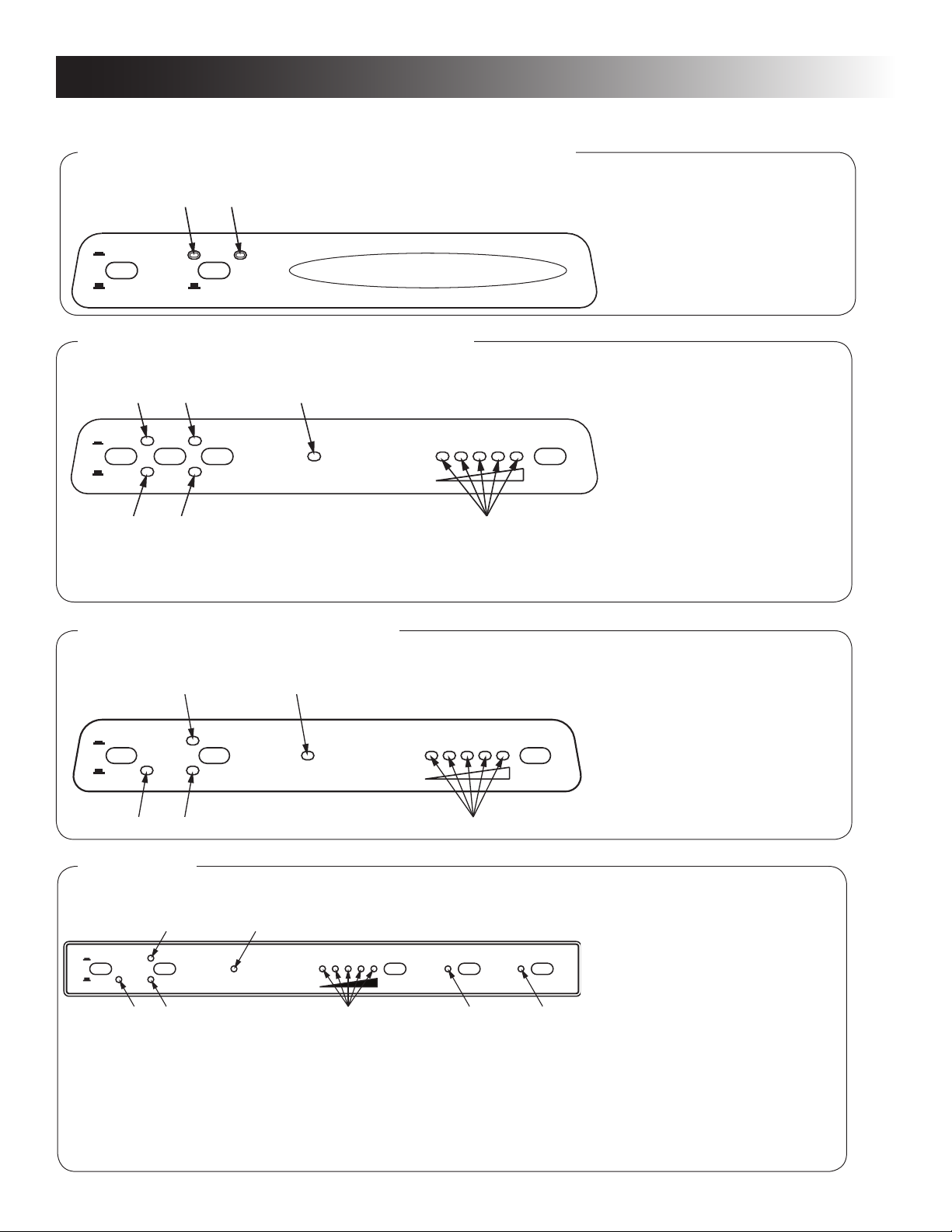
CONTROL PANEL
RM2351, RM2451, RM2551, DM2652 & DM2852
A B
1. ON/OFF button (main power)
2. AUTO/GAS mode selector
button
AUTO
ON
1 2
OFF
GAS
CHECK
AUTOMATIC REFRIGERATOR TEMPERATURE CONTROL
RM2354, RM2454, RM2554 & DM2663
A D E
COLD
ON
DC
AUTO
1 2
1 2 3 4
OFF
AC
GAS
CHECK
DM2662, DM2862 & NDM1062
A D
A. AUTO mode indicator lamp
B. CHECK indicator lamp
(GAS mode only)
1. ON/OFF button (main power)
2. DC mode selector button
3. AUTO/GAS mode selector
button
4
COLDEST
5
3
4. Temperature selector button
A. DC mode indicator lamp
B. AC mode indicator lamp
C. GAS mode indicator lamp
D. AUTO mode indicator lamp
E. CHECK indicator lamp
(GAS mode only)
F. Temperature indicator lamps
1. ON/OFF button (main power)
2. AUTO/GAS mode selector
button
3. Temperature selector button
ON
AUTO
COLD
1 2
3
4
5
21
OFF
B C
AC
GAS
CHECK
E
NDM1062
B
AES
ON
1 2 3 4 5
OFF
AUTO
AC
GAS
CHECK
D
COLD
1
2
345
COLDEST CLC
4
COLDEST
3
LAC
A. AUTO mode indicator lamp
B. AC mode indicator lamp
C. GAS mode indicator lamp
D. CHECK indicator lamp
E. Temperature indicator lamps
1. ON/OFF button (main power)
2. AES/AUTO/GAS mode
selector button
3. Temperature selector button
4. Climate control button
5. Low ambient control button
A. AC mode indicator lamp
B. AES/AUTO mode indicator lamp
C. GAS mode indicator lamp
D. CHECK indicator lamp
E. Temperature indicator lamps
F. Climate control indicator lamp
G. Low ambient control indicator
lamp
Page 5

REFRIGERATOR OVERVIEW
MODES OF OPERATION
AUTO MODE - AES/AUTO MODE
When operating in AUTO - AES/AUTO mode, the AUTO
- AES/AUTO mode indicator lamp is illuminated. The control system will automatically select between AC and GAS
operation. AC has priority over GAS. Should AC become
unavailable, the system automatically switches to GAS.
As soon as AC becomes available again, the control will
switch back to AC regardless of the status of the GAS
operation.
If the CHECK indicator lamp is illuminated the controls
have failed to ignite the burner in the GAS mode. To restart an ignition attempt with the CHECK lamp illuminated
(or to turn off the CHECK lamp), press the ON/OFF button
OFF and back ON again. The control system activates
the ignition system and makes three attempts to light the
burner for a period of approximately 45 seconds at two
minutes interval. Should 120 VAC become available while
the CHECK indicator lamp is on, the CHECK lamp will not
turn off until the ON/OFF button is pressed OFF and then
ON again.
GAS MODE
RM2351, RM2451, RM2551, DM2652 & DM2852:
When operating in GAS mode, the AUTO mode indicator
lamp will be off.
RM2354, RM2454, RM2554, DM2662, DM2663, DM2862 &
NDM1062: When operating in GAS mode, the GAS Mode
indictor lamp is illuminated.
This mode provides LP gas only. The control system acti-
vates the ignition system and attempts to light the burner
for a period of approximately 45 seconds at two minutes
interval. If unsuccessful, the CHECK indicator lamp will
illuminate.
To restart GAS operation, press the ON/OFF button to
OFF and then back ON. The control system attempts a
new ignition sequence.
LIMP MODE OF OPERATION
In the event of a failure of a major operating component,
the control system will continue to operate the cooling
system.
RM2351, RM2451, RM2551, DM2652 & DM2852
If the control can not read the temperature sensor and
control the preset temperature, the control will run the
cooling unit continuously at the energy source available.
The refrigerator will continue to operate in this mode indenitely - or - until a new sensor is installed and the system reset.
RM2354, RM2454, RM2554, DM2662, DM2663, DM2862 &
NDM1062
Two modes of operation can occur:
1) The rst limp mode of operation will execute if the
display module becomes non functional. The control
system reverts to full automatic operation selecting
the best energy source available with AC, DC (3way only) and GAS priority. The temperature setting
is maintained at the mid position. The power module
will continually attempt to reestablish operation of the
display module.
2) The second limp mode of operation will execute when
a failure of the temperature sensing device or associated electronic circuitry occurs. If this should happen,
the control system operates on the energy source selected via the control panel. The cooling unit runs continuously on the selected energy source. The refrig-
erator continues to operate in this mode indenitely or
until a new sensor is installed and the system is reset.
DC MODE
RM2354, RM2454, RM2554 & DM2663
When operating in DC mode (3-way models only), the DC
mode indicator lamp is illuminated and all other lamps
are off. To select another operating mode, turn off the DC
mode by pressing the DC selector button. The DC lamp
is turned off.
When there is no charging of the house battery, switch to
AUTO mode or GAS mode since running the refrigerator on
12 VDC will quickly drain the battery.
5
Page 6
INSTRUCTIONS FOR USE
STARTING THE REFRIGERATOR
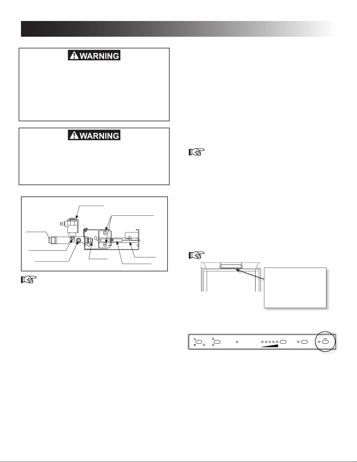
FIRE HAZARD. When the RV has not been
used for some time, make sure that the path
between the burner jet and the burner tube
has not been obstructed before lighting the
LP gas burner. Failure to obey this warning
could cause a re resulting in death or serious injury.
FIRE OR EXPLOSION HAZARD. When refueling or parked near gasoline pumps shut off all
LP gas appliances. Failure to obey this warning could cause a re or explosion resulting
in death or serious injury
LP GAS EQUIPMENT ASSEMBLY
SOLENOID VALVE
BURNER MOUNTING SCREWS
INLET FITTING
MANUAL SHUTOFF VALVE
Shown in open position
PRESSURE TEST PORT
BURNER JET
BURNER TUBE
SPARK ELECTRODE
- DC mode (3-way models only)
Press the DC mode indicator button. The DC
lamp will be turned on. To select AUTO or GAS
mode, turn off the DC mode by pressing the
DC mode selector button. The DC lamp will
then be turned off.
ADJUSTING THE THERMOSTAT
RM2354, RM2454, RM2554, DM2662, DM2663, DM2862
& NDM1062
The thermostat controls both the gas and electric operation, thereby eliminating the necessity of resetting each
time a different energy source is employed. After the initial
start-up, the thermostat should be adjusted to the desired
temperature setting.
1. Press the temperature selector button until the
lamp at the desired setting is illuminated.
RM2351, RM2451, RM2551, DM2652 & DM2852
The temperature is controlled by a factory preset temperature setting.
COLD WEATHER LOW AMBIENT
CONTROL
NDM1062
The refrigerator is equipped with an exclusive feature that
allows for trouble-free operation in low ambient temperature (like below 50°F) for extended periods of time. Once
the outdoor temperature is above 50°F, the low ambient
switch should be turned off.
1. Turn the Low ambient control switch to I (ON).
1. Check that all the manual gas valves are in the
ON position.
2. Make sure that a continuous 12 VDC supply is
available for the electronic control to function.
3. Press the ON/OFF button.
4. Select operation mode:
- AUTO - AES/AUTO mode (AC and Gas)
Press the AUTO/GAS - AES/AUTO/Gas mode
selector button (if not already on). The illuminated lamp indicates the selected mode.
(If the CHECK indicator lamp is illuminated,
see REFRIGERATOR OVERVIEW > MODES
OF OPERATION > AUTO MODE - AES/AUTO
MODE for further information.)
- GAS mode (LP gas operation only)
Press the AUTO/GAS - AES/AUTO/Gas mode
selector button to turn off the AUTO mode (if
not already off).
(Within 45 seconds the burner should be ignited and operating normally. If not, see REFRIGERATOR OVERVIEW > MODES OF
OPERATION > GAS MODE for further information.)
The Low ambient control
switch is located beneath
the top decoration panel
that houses the control
panel.
2. Press the LAC button. The indicator lamp will
illuminate.
AES
ON
OFF
6
AUTO
AC
GAS
CHECK
COLD
1
2
COLDEST CLC
345
LAC
Page 7
INSTRUCTIONS FOR USE
EXTREME COLD WEATHER
OPERATION
Refrigerator performance may be reduced in extremely
cold (subzero) temperatures. This temporary condition is
normal for absorption refrigerators and does not indicate
product failure. In the event that performance is reduced
in such conditions, turn the refrigerator off. As ambient
temperatures rise, please restart your refrigerator according to instructions before requesting service.
CLIMATE CONTROL SYSTEM
NDM1062
During the summer months of high temperature and
humidity, the metal frame between the freezer and fresh
food compartments may have water droplets forming. The
number of water droplets will increase if the vehicle is not air
conditioned during these months. The refrigerator comes
standard with a 12 VDC climate control that will evaporate
the water droplets when they form. The climate control can
be left on continuously or used only when temperatures
require it. Note that when turned on, the climate control
will draw 12 VDC power continuously. Turn it off when a
charging source is not available.
1. Turn the climate control switch to I (ON).
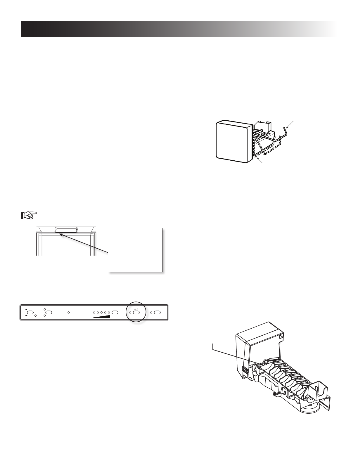
OPERATING THE ICE MAKER
(ICE MAKER MODELS ONLY)
Before the ice maker can operate, make sure that:
• The refrigerator is connected to 120 VAC .
• The water valve supplying the refrigerator is turned on.
• The ice level bail arm is in its fully down position.
Keep bail arm in the up (OFF) position until water is present at the ice maker.
Ice level
bail arm
Down
position
When the ice maker thermostat senses the preset tempera-
ture for the ejection of the ice cubes, the ngers will start to
rotate, dumping any ice cubes and lling the mold with water.
When the storage container is full, the bail arm will come
in contact with the ice cubes. The bail arm cannot return
to the full down position and the ice production is stopped
until the bin is emptied, or ice cubes are removed.
The Climate control
switch is located beneath the top decoration panel that houses
the control panel.
2. Press the CLC button. The indicator lamp will
illuminate.
AES
ON
OFF
AUTO
AC
GAS
CHECK
COLD
1
345
2
COLDEST CLC
To prevent water from splashing out of the mold assembly
while travelling in your recreational vehicle, raise the bail
arm to the full UP/OFF position about 1-1/2 hours before
departing. This will allow the water in the mold to freeze.
WATER SUPPLY
The water supply system must have a minimum pressure
of 15 pounds per square inch gauge (psig). A 1/4” diameter water line to the water valve should be used at the rear
of the refrigerator. The water line must have a manual
shutoff valve placed where it is easily accessible.
LAC
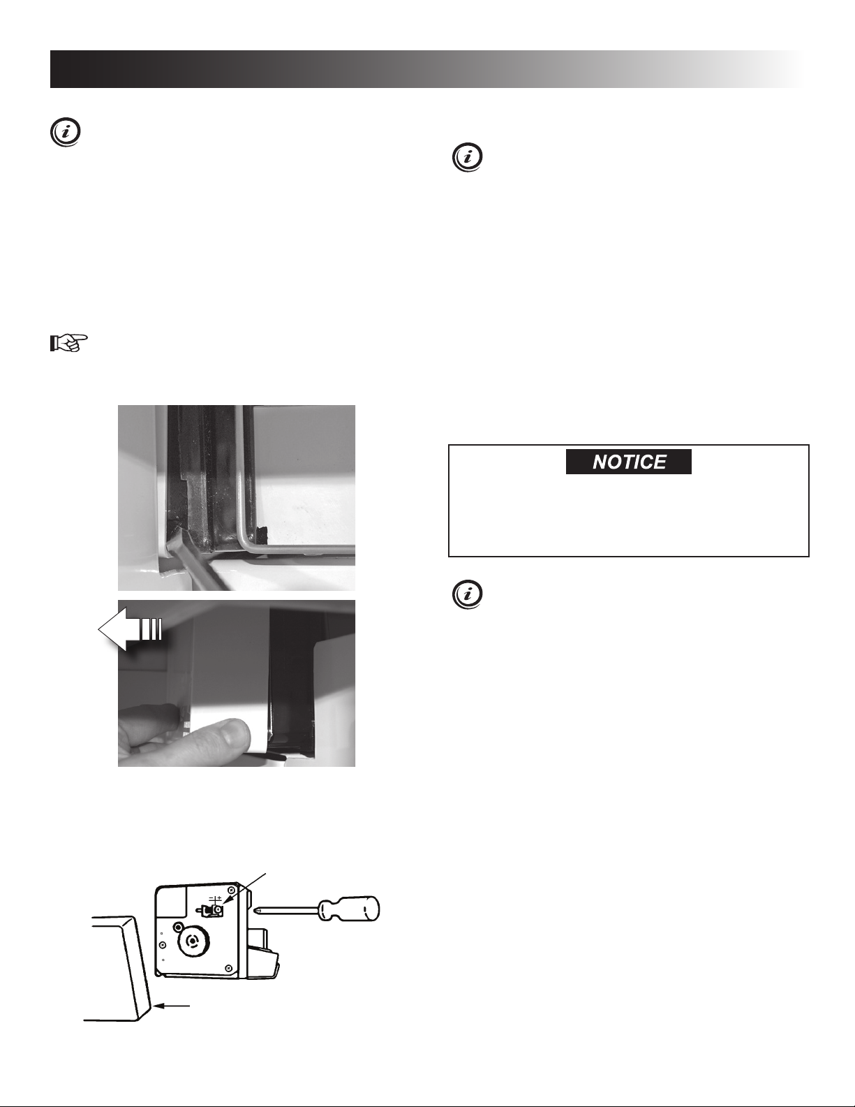
The maximum water level is represented by a thin line. It
is essential that the water level does not exceed this line!
Maximum
water level
If necessary,change the water ow by adjusting the water
supply. For instructions, see ADJUSTING THE SIZE OF
CUBES.
7
Page 8
INSTRUCTIONS FOR USE
ADJUSTING THE SIZE OF CUBES
If the ice maker was cleaned and drained, no ice
cubes will be dumped into the bin during the rst
cycle.
The rst few cycles may have small cubes due to air
trapped in the water lines. The rst container of ice cubes
should be dumped if the water system has been winterized or not used for several weeks. Once the ice maker has run through several cycles and if cubes are too
small or sticking together, adjustment is necessary on the
amount of water entering the mold.
TO ADJUST THE SIZE OF CUBES, FOLLOW THESE
STEPS:
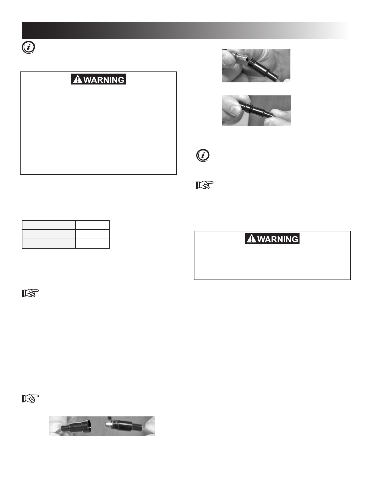
1. Remove the protective cover from the ice mak-
er mechanism. Using a at-head screwdriver,
place the tip of the screwdriver in the slot. Twist
the screwdriver blade gently to loosen the cover.
3. Turn the screw clockwise to decrease the cube
size or if the mold is overlling, and the cubes
are stuck together.
To prevent overlling, do not turn the adjustment
screw more than one revolution at a time. Allow
the ice maker to cycle several times before another
adjustment is made. Be sure to replace the protective cover on the cycle after the adjustments are
complete.
TURNING OFF THE REFRIGERATOR, AND
WHEN NOT IN USE
You can turn off your refrigerator by pressing the main
power ON/OFF button found on the control panel to the
OFF position. This will shut off all power to the refrigerator,
including DC power to the refrigerator.
If the refrigerator will not be in operation for an extended
period of time or put into winter storage it should be emp-
tied, defrosted, cleaned, and the doors placed in the airing
position. If ice cube trays are in use, they should also be
dried and kept outside the cabinet.
This refrigerator is intended for continuous
use. Do not allow it to run unattended when
there is a risk for loss of electricity or fuel.
Food spoilage could occur.
2. Locate the adjusting screw under the protective cover. Turn the screw counterclockwise to
increase the size of cubes.
Adjusting screw
The refrigerator’s control system still consumes a
few milliamps even if it is turned off. If your RV is
being put into winter storage, it is recommended to
either put your RV batteries on a battery charger or
turn off the vehicle’s main 12 VDC switch. This will
prevent the RV battery from discharging.
Cover
8
Page 9
STORAGE COMPARTMENTS
FIRE OR EXPLOSION HAZARD. Do not store
or use gasoline, oil or gasoline soaked rags,
or other ammable vapors and liquids in the
service area behind the refrigerator or in the
vicinity of this or any other gas appliance.
Failure to obey this warning could cause a
re or an explosion resulting in death or serious injury.
REFRIGERATOR VOLUME
MODEL TOTAL REFRIGERATED
VOLUME (CU. FT.)
RM2351& RM2354 3
RM2451& RM2454 4
RM2551 & RM2554 5
DM2652, DM2662 & DM2663 6
DM2852 & DM2862 8
NDM1062 9.2
FOOD STORAGE COMPARTMENT
• Cool the refrigerator before placing any food inside.
Never put hot food or drinks into the refrigerator - cool
them rst.
• The food storage compartment is completely closed and
unventilated, which is necessary to maintain the required
low temperature for food storage. Consequently, foods
having a strong odor or those that absorb odors easily
should be covered.
• Vegetables, salads, etc. should be covered to retain
their crispness.
• The coldest positions in the refrigerator are under the
cooling ns and at the bottom of the refrigerator. The
warmer areas are on the upper door shelves. This
should be considered when placing different types of
food in the refrigerator.
• Arrange all food in the unit to allow for free air circulation. Do not overpack because a stuffed refrigerator
must work harder and will have higher cabinet temperatures.
• Do not leave the unit’s door open any longer than necessary. This will reduce frost formation and increase the
efciency of the refrigerator.
FROZEN FOOD STORAGE
COMPARTMENT
This compartment is not designed for deep or quick freezing of food.
• To prevent food from drying out, keep it in covered
dishes, containers, plastic bags or wrapped in aluminum foil.
• Meat or sh, whether raw or prepared, can be stored in
the frozen food storage compartment provided they are
precooled rst in the refrigerator. They can be stored
about three times longer in the frozen food compartment as compared to the fresh food compartment.
• Quick frozen soft fruits and ice cream should be placed
in the coldest part of the compartment, which is at the
bottom of the aluminum liner.
• Frozen vegetables, may be stored in any part of the
compartment.
• To prevent frost buildup, which can reduce the efcien-
cy, wipe excess moisture off items being placed in the
compartment.
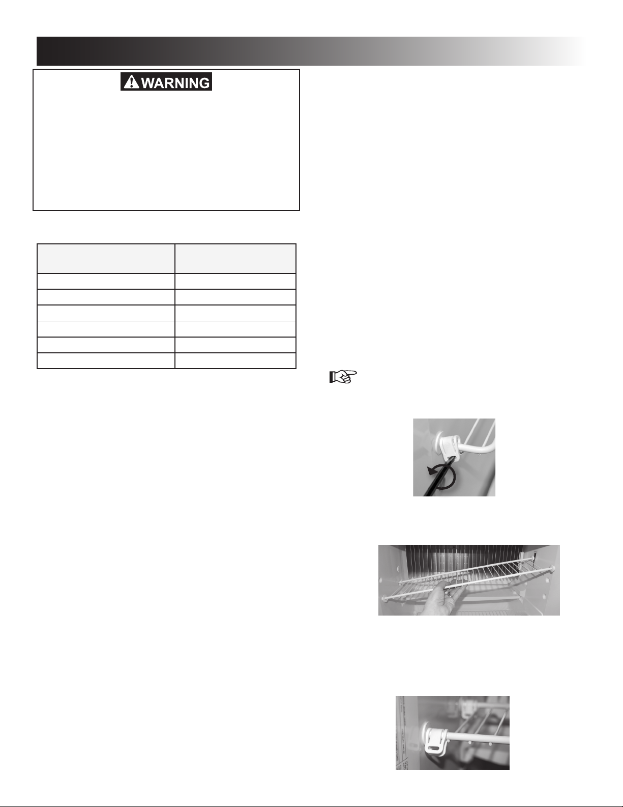
REMOVING AND REPLACING THE
SHELVES
1. Remove the shelf locks by inserting the tip of a
at bladed screwdriver into the slot of the locks.
Turn the screwdriver counterclockwise and then
remove the shelf locks from the wire shelf.
2. Slide the shelf to the left until bushings disengage, then tilt the shelf to one side at an angle
while pulling forward.
3. Reposition the shelf in the desired location. Insert the ends of the wire shelf on the left-hand
side and slide the shelf into the holes on the
right-hand side.
4. Slide the plastic plugs into the holes of the wall.
5. Snap the shelf locks back onto the wire shelf.
9
Page 10
STORAGE COMPARTMENTS
ICE CUBES
Ice cubes can be made in the freezer compartment. For
faster freezing, place trays in direct contact with the bottom
of the freezer compartment.
PRODUCT CARE
DEFROSTING
1. Shut off the refrigerator by pressing the main
power ON/OFF button (OFF position).
2. Empty the refrigerator.
3. Leave the cabinet and freezer doors open and
make sure the drip tray is in place under the
nned evaporator.
Defrosting time can be reduced by lling ice trays
with hot water and placing them in the freezer compartment.
RM2351, RM2454, RM2554, DM2662, DM2663, DM2862
& NDM1062
Ice will be made more rapidly if the thermostat is set at its
highest position, but be sure to move the thermostat back
to normal setting when ice is formed; the refrigerator might
otherwise become too cold.
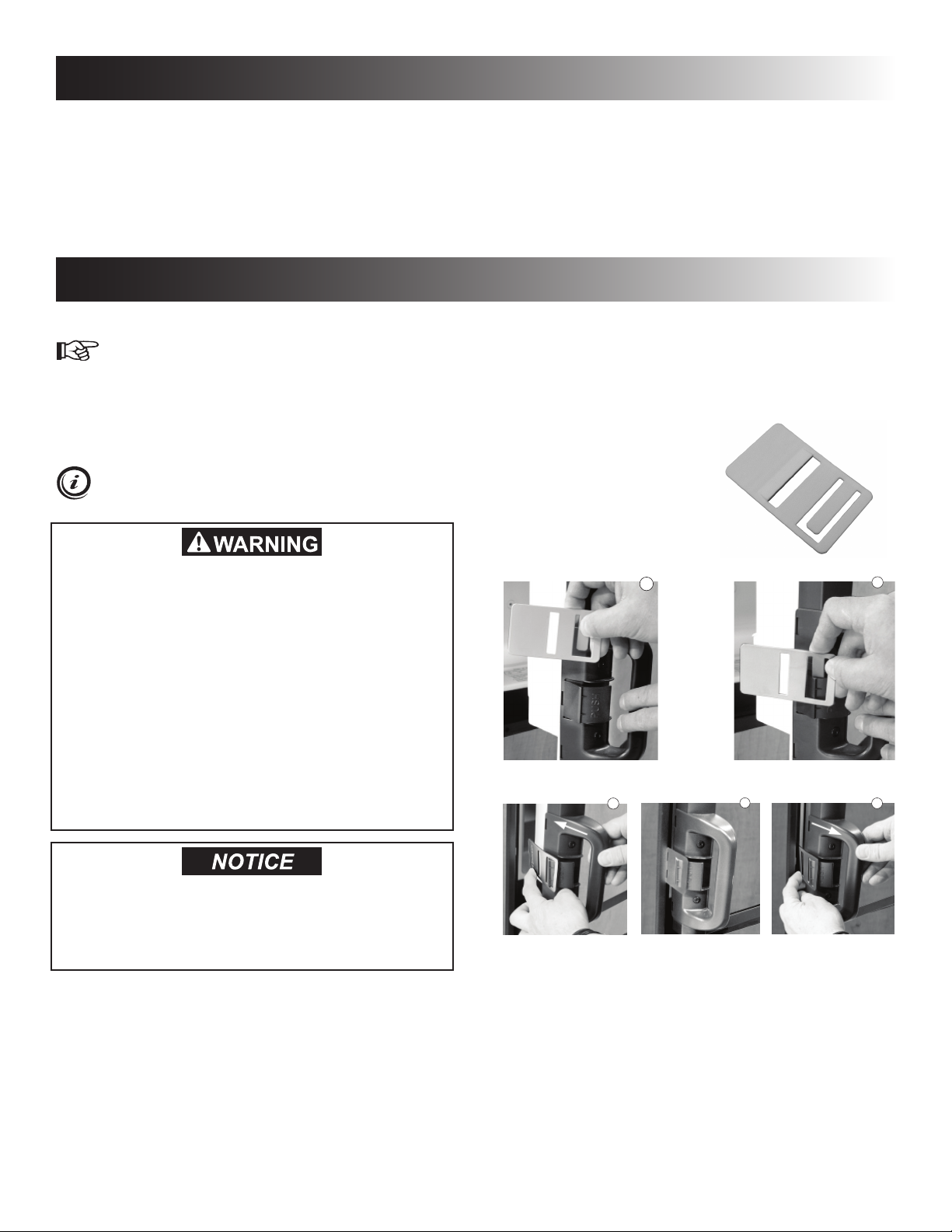
AIRING POSITION
DM2652, DM2662, DM2663, DM2852 &
DM2862
Use the airing position card
to keep the doors ajar if the
refrigerator is put in storage
or will not be used for an extended period of time.
FIRE AND INHALATION HAZARD. Do not use
a knife, ice pick, or any other sharp tool to
remove frost from the freezer compartment.
Failure to obey this warning could cause a
leak in the ammonia cooling system which
could lead to a re hazard resulting in death
or serious injury.
An ammonia leak also poses an inhalation
hazard, and could cause chemical burns to
the skin and eyes. Exposure to a high concentration of ammonia could result in death
or serious injury.
Do not use a hot air blower to remove frost
from the freezer compartment. Permanent
damage could result from warping the metal
or plastic parts.
4. When all the frost has melted, dry the interior
with a clean cloth and turn the refrigerator back
on.
RM2354, RM2454, RM2554, DM2662, DM2663, DM2862
& NDM1062
5. Set the thermostat to the coldest setting for a
few hours. Then, reset the thermostat to the
desired setting, usually at mid setting. Replace
food after refrigerator has reached appropriate
cool temperature.
1
3
4
2
5
10
Page 11
PRODUCT CARE
CLEANING
Always keep the refrigerator clean. Cleaning the refrigerator is usually done after it is defrosted or put into storage.
Use a lukewarm, weak soda solution to clean the interior
liner of the refrigerator. Use warm water only to clean the
nned evaporator, gasket, and shelves. Do not spray liquids near electrical outlets, connections, or the refrigerator
components.
After cleaning the interior liner/evaporator ns, make sure
thermistor bulb and thermistor bracket are properly positioned. See “Troubleshooting” on page 14.
Do not use strong chemicals or abrasives to
clean these parts, as the protective surfaces
will be damaged.
To keep the refrigerator operating efciently, periodic inspection and cleaning of several components once a year
is recommended:
• Check the lower vent, upper vent and area between
these openings for any obstructions such as bird/insect
nests, spider webs, etc.
• Make sure the refrigerator area is free from combusti-
ble material, gasoline and other ammable vapors or
liquids.
STORAGE PROCEDURE/ WINTERIZING THE REFRIGERATOR
(ICE MAKER MODELS ONLY)
The refrigerator is equipped with a heater tape wrapped
around the water solenoid valve and outlet water tube.
During cold weather operation below 32°F/0°C the automatic temperature switch will turn the heater tape on
automatically.
If the RV will not be in use for an extended period of time
or put into storage:
• Drain the RV water system.
• Disconnect the water lines from the inlet and outlet
sides of the water valve. Drain the lines into a cup and
allow the lines to dry.
• The ice maker should be drained and dried. Note that
this procedure must be performed by a qualied service technician.
• Using a lukewarm soda solution, clean the interior
liner of the refrigerator. Clean the nned evaporator
and shelves. Use warm water only and never strong
chemicals or abrasives since these can damage the
protective surfaces.
• Place doors in the airing position.
FIRE OR EXPLOSION HAZARD. Do not store
or use gasoline, oil or gasoline soaked rags,
or other ammable vapors and liquids in the
service area behind the refrigerator or in the
vicinity of this or any other gas appliance.
Failure to obey this warning could cause a
re or an explosion resulting in death or serious injury.
• If accessible, clean the coils on the back of the refrigerator. Use a soft bristled brush to dust off the coils.
11
Page 12
MAINTENANCE & SERVICE
To keep the refrigerator working properly, a qualied service technician should, at least once a year,
inspect the connections, the control system, the LP
gas pressure and ue bafe.
FIRE AND INHALATION HAZARD. If the refrigerator stops working -or- if it emits an ammonia smell, immediately turn the refrigerator
off, leave the vicinity, and contact a Service
Center.
A high concentration of ammonia refrigerant could cause an inhalation hazard, could
cause chemical burns to the skin and eyes,
and could cause a re resulting in death or
serious injury.
REPLACING THE FUSES
2-way models are equipped with 2 fuses - one for the
refrigerator control system and one for the AC heater.
3-way models are equipped with 3 fuses - two fuses in
the power module and one in-line blade fuse.
Control system 3 A
AC heater 5 A
12 VDC heater 30 A
REPLACING THE FUSES
POWER MODULE
To replace the fuses, follow these steps:
1. Turn off the refrigerator and unplug the power
cord and disconnect the 12V wires.
2. Remove the power module cover.
3. Snap the fuse out of the fuse holder and t the
new fuse in to the fuse holder.
4. Put back the power module cover.
3. Replace the fuse.
4. Put the holder back together.
PERIODIC MAINTENANCE
To be performed by a qualied service technician
only.
CHECKING THE LP GAS CONNECTIONS
1. Check all connections in the LP gas system (at
the back of the refrigerator) for gas leaks. The
LP gas supply must be turned on.
2. Apply an approved leak detection solution to all
LP gas connections. The appearance of bubbles indicates a leak and should be repaired immediately!
FIRE OR EXPLOSION HAZARD. Never use an
open ame to check for gas leaks. Failure to
obey this warning could cause a re or explosion resulting in death or serious injury.
CHECKING THE CONTROL SYSTEM
Check the control system by connecting/disconnecting the
120 VAC power, starting/stopping the engine, etc.
DM2652 (OPTIONAL FAN), DM2852 (OPTIONAL FAN),
DM2862 (OPTIONAL FAN) & NDM1062
INLINE FUSE
The inline fuse for the power vent fans is connected to
the 12V DC socket.
To replace the inline fuse, follow these steps:
1. Disconnect 12V DC power.
2. Open the fuse holder.
12
Page 13
MAINTENANCE & SERVICE
CLEANING THE BURNER
1. Turn off the refrigerator
2. Unplug the power cord from the 120 VAC outlet. Disconnect the wires or shut off the 12 VDC
power supply to the refrigerator.
3. Turn off the manual shut off valve.
4. Remove cover from burner housing.
5. Clean the burner tube with a brush. Blow out the
burner with compressed air.
FIRE HAZARD. Never use a wire or pin to clear
obstructions from the burner jet as damage
will occur. Do not attempt to adjust the burner
jet. Failure to obey this warning could cause
a re resulting in death or serious injury.
REFRIGERATOR REMOVAL / DISPOSAL
To be performed by a qualied service technician
only.
See Installation Instructions for refrigerator removal /
replacement procedure, and for recycle information.
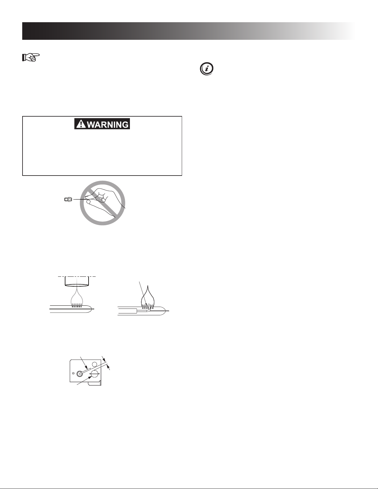
6. Verify that the burner jet slots are centered un-
der the ue tube.
7. Be sure to check the burner ame for proper appearance. The ame should be clear blue over
the slots of the burner.
Clear Blue Color
Of Flame
Slots Centered
Under Flue Tube
8. Check the electrode for proper location and gap.
Adjustments may be made with needle nose pliers if necessary.
Electrode
Burner Tube
9. Turn on the manual gas shut off valve.
10. Examine all ttings for leaks. Use a commercial
non-corrosive bubble solution.
11. Connect the 120 VAC power cord.
12. Reconnect/Turn on the 12 VDC power.
13. Check LP gas safety shutoff.
1/8" to 3/16"
(3-5 mm)
13
Page 14
TROUBLESHOOTING
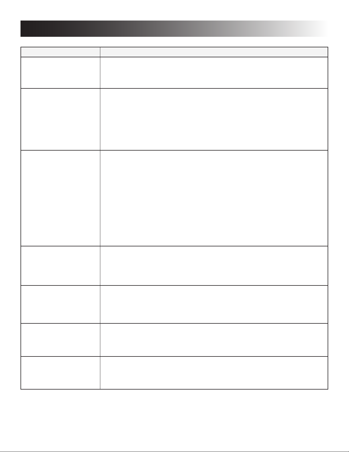
If you run into a problem, refer to the troubleshooting table below.
Symptom Check/Remedial action
Refrigerator stops cooling. • Immediately turn the refrigerator off and contact a Dometic dealer or Service Center.
NOTE! Do not leave it running for an extended period of time, and never try to solve the
problem by repeatedly restarting the refrigerator.
• Do not use the refrigerator until it has been repaired
Refrigerator emits an ammonia smell
• Immediately turn the refrigerator off at the front control panel.
• Do NOT open refrigerator doors.
• Open coach windows and doors (to air out the coach) and evacuate.
• Turn off manual LP gas valve at rear of refrigerator.
• Disconnect the 120 VAC power at rear of refrigerator.
• Contact a Dometic dealer or Service Center for repair.
• Do not use the refrigerator until it has been repaired.
Refrigerator or freezer is not
cold enough
Refrigerator does not work
on electric
The refrigerator does not
work in gas operation mode
• For refrigerators equipped with a thermostat, check the thermostat and adjust if
necessary.
• Is the plug rmly connected to the socket? Is the socket switched on?
Check the socket by plugging in another appliance.
• Is the refrigerator level? (Due to the nature of its operation it is important to keep an
absorption refrigerator level.)
• Door closing properly? Check the door gasket.
• Heavy frost build-up on evaporator ns? To prevent frost build-up do not leave the unit’s
door open longer than necessary.
• Over packed refrigerator? The unit will have to work harder if the refrigerator is stuffed,
and results in higher cabinet temperatures. Arrange the food in the unit to allow for free
air circulation.
• Is the plug rmly connected to the receptacle? Is the receptacle energized? Check the
receptacle by plugging in another appliance.
• Is there a power failure?
• Blown fuse. Turn refrigerator off and contact a Dometic dealer or Service Center for
repair.
• LP gas bottle empty? Change the gas bottle.
• Air in the gas line? Remove the air by repeating the ignition sequence.
• If problem resists, turn refrigerator off and contact a Dometic dealer or Service Center
for repair.
Refrigerator emits an odor
from fumes:
Refrigerator too cold • Dislocated thermistor bracket. Clip thermistor bracket to last n on right side of cooling
If the problem persists and the refrigerator is still not working properly, turn refrigerator off and contact your nearest Service Center. State the problem, model, product, and serial number. These details are stated on the data label inside the
refrigerator compartment.
• Dislocated or damaged burner. Turn refrigerator off and contact a Dometic dealer or
Service Center for repair.
• Dirty ue tube. Turn refrigerator off and contact a Dometic dealer or Service Center for
repair.
ange and center vertically on n.
• Dislocated thermistor bulb. Position thermistor bulb inside thermistor bracket groove
and center vertically in bracket.
14
Page 15
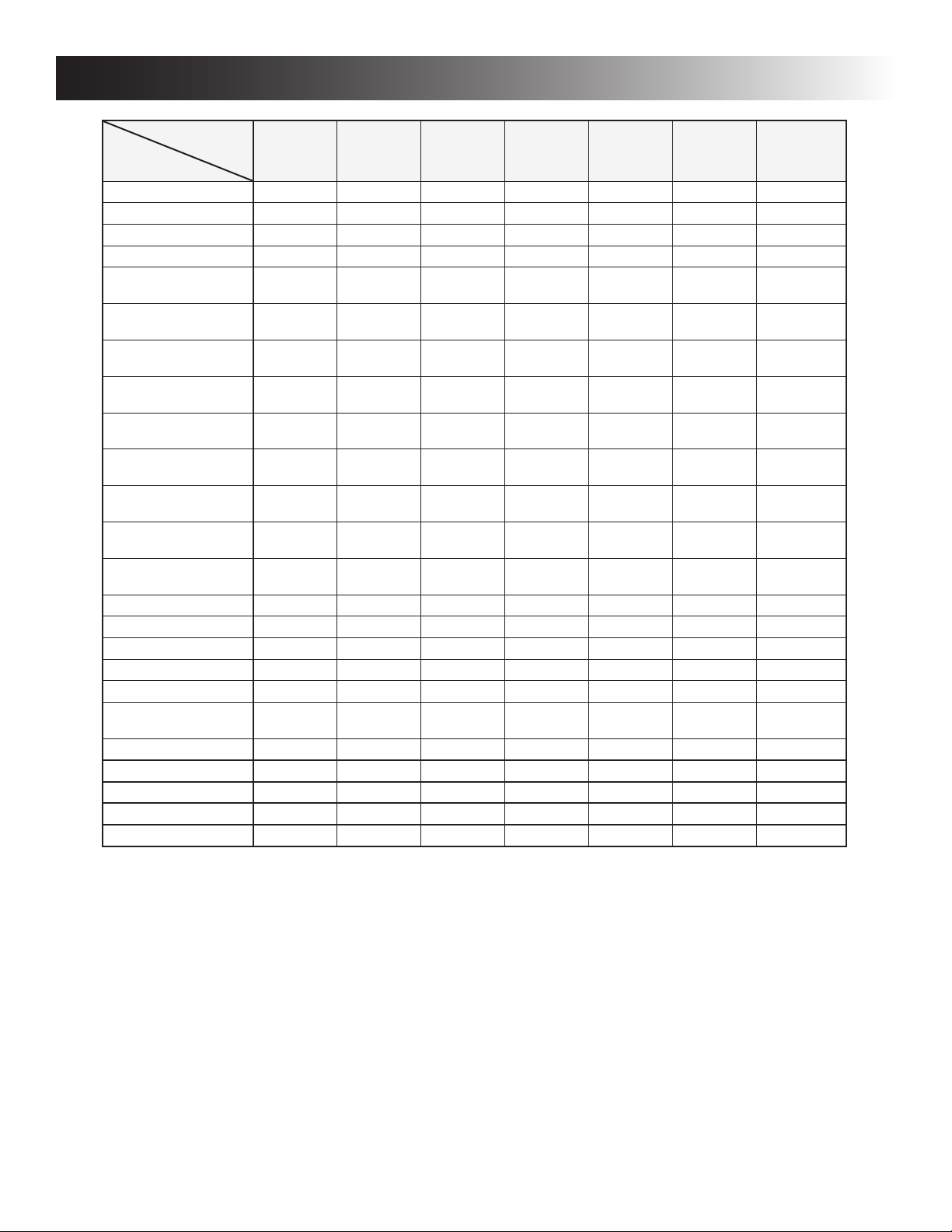
APPENDIX A - SPARE PARTS
MODEL
SPARE PARTS
Airing position card N/A N/A N/A N/A N/A N/A 3312986.403
Bafe 2007172022 2007172022 2932667013 2932667013 2932667021 2932667021 2932667039
Box 2932636018 2932636018 N/A N/A N/A N/A N/A
Box, vegetable N/A N/A N/A N/A 2932621010 2932621010 2932621010
Box, vegetable
(crisper), 2 pieces
Box, vegetable
(meat locker)
Burner
(with conductor)
Door reversing kit,
(light brown)
Door reversing kit,
(black)
Door reversing kit,
right-left (light brown)
Door reversing kit,
left-right (light brown)
Door reversing kit,
right-left (black)
Door reversing kit,
left-right (black)
Door shelf, lower N/A N/A 2932575018 2932575018 2932575018 2932575018 2932575018
Door shelf, (2 pieces) N/A N/A 2932576016 2932576016 N/A N/A 2932576016
Door shelf, (3 pieces) 2002261242 2002261242 N/A N/A 2932576016 2932576016 N/A
Door shelf, freezer N/A N/A N/A N/A N/A N/A 2932577014
Electrode 2932781012 2932781012 2932781012 2932781012 2932781012 2932781012 2932781012
Halogen lamp
(12V, 10W base G4)
Handle (black) N/A N/A 2932670025 2932670025 2932670025 2932670025 3851174023
Heater 175W, 12V N/A 3850646104 N/A 3850646104 N/A 3850646104 N/A
Heater 175W, 120V 3850644455 3850644455 3850644455 3850644455 3850644455 3850644455 N/A
Heater 275W, 12V N/A N/A N/A N/A N/A N/A N/A
Heater 325W, 120V N/A N/A N/A N/A N/A N/A 3850644422
RM2351 RM2354 RM2451 RM2454 RM2551 RM2554 DM2652
N/A N/A N/A N/A N/A N/A N/A
N/A N/A N/A N/A N/A N/A N/A
2930697079 2930697079 2930697079 2930697079 2930697079 2930697079 2930697079
385030401 385030401 N/A N/A N/A N/A N/A
385030402 385030402 N/A N/A N/A N/A N/A
N/A N/A 293275002 293275002 293275002 293275002 293275008
N/A N/A 293275003 293275003 293275003 293275003 293275009
N/A N/A 293275013 293275013 293275013 293275013 293275011
N/A N/A 293275014 293275014 293275014 293275014 293275012
N/A N/A N/A N/A N/A N/A N/A
15
Page 16
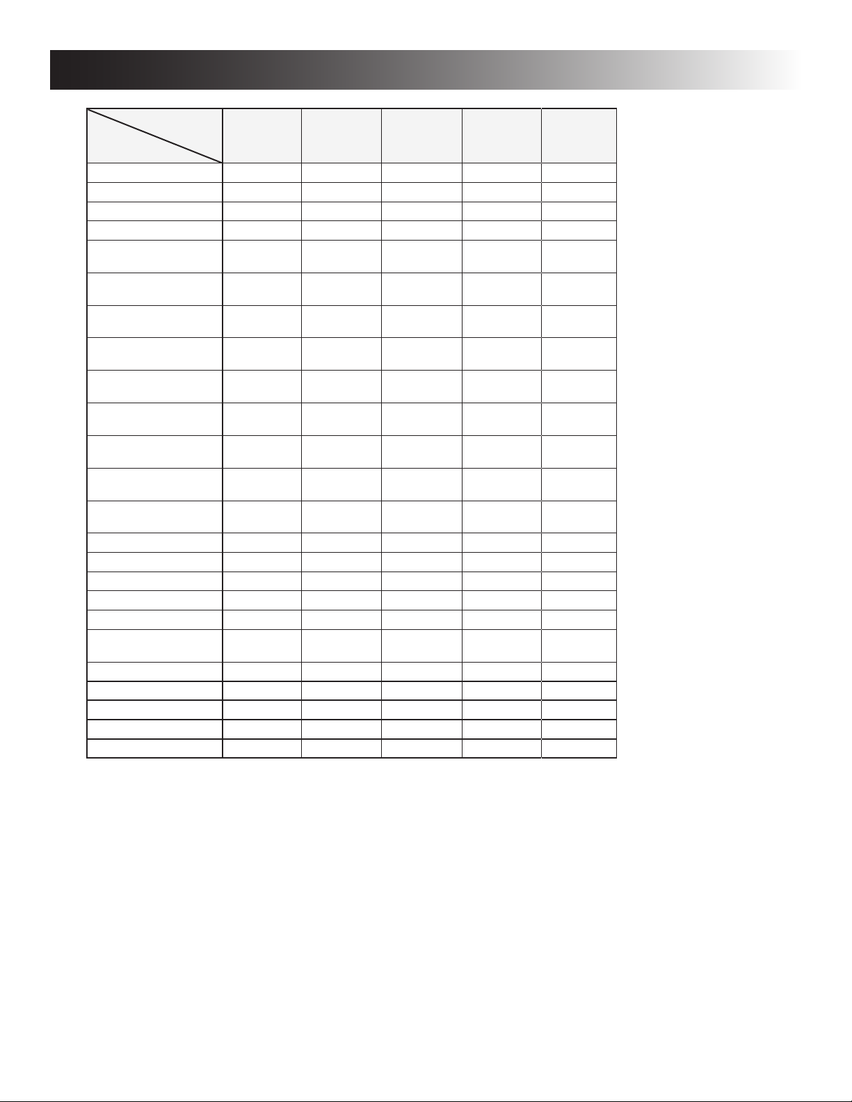
APPENDIX A - SPARE PARTS
MODEL
SPARE PARTS
Airing position card 3312986.403 3312986.403 3312986.403 3312986.403 N/A
Bafe 2932667039 2932667039 2932667047 2932667047 2932667047
Box N/A N/A N/A N/A N/A
Box, vegetable 2932621077 2932621077 2932621010 2932621077 N/A
Box, vegetable
(crisper), 2 pieces
Box, vegetable
(meat locker)
Burner
(with conductor)
Door reversing kit,
(light brown)
Door reversing kit,
(black)
Door reversing kit,
right-left (light brown)
Door reversing kit,
left-right (light brown)
Door reversing kit,
right-left (black)
Door reversing kit,
left-right (black)
Door shelf, lower 2932575059 2932575059 2932575018 2932575059 2932575075
Door shelf, (2 pieces) 2932576065 2932576065 N/A N/A N/A
Door shelf, (3 pieces) N/A N/A 2932576016 2932576065 2932576081
Door shelf, freezer N/A N/A 2932577014 N/A N/A
Electrode 2932781012 2932781012 2932781012 2932781012 2932781012
Halogen lamp
(12V, 10W base G4)
Handle (black) 3851174023 3851174023 3851174023 3851174023 2932094044
Heater 175W, 12V N/A N/A N/A N/A N/A
Heater 175W, 120V N/A N/A N/A N/A N/A
Heater 275W, 12V N/A 3850646096 N/A N/A N/A
Heater 325W, 120V 3850644422 3850644422 3850644422 3850644422 3850644422
DM2662 DM2663 DM2852 DM2862 NDM1062
N/A N/A N/A N/A 2002726178
N/A N/A N/A N/A 2932621085
2930697079 2930697079 2930697079 2930697079 2930697079
N/A N/A N/A N/A N/A
N/A N/A N/A N/A N/A
N/A N/A 293275008 N/A N/A
N/A N/A 293275009 N/A N/A
293275011 293275011 293275011 293275011 293275011
293275012 293275012 293275012 293275012 293275012
N/A N/A N/A N/A 3850455019
16
Page 17
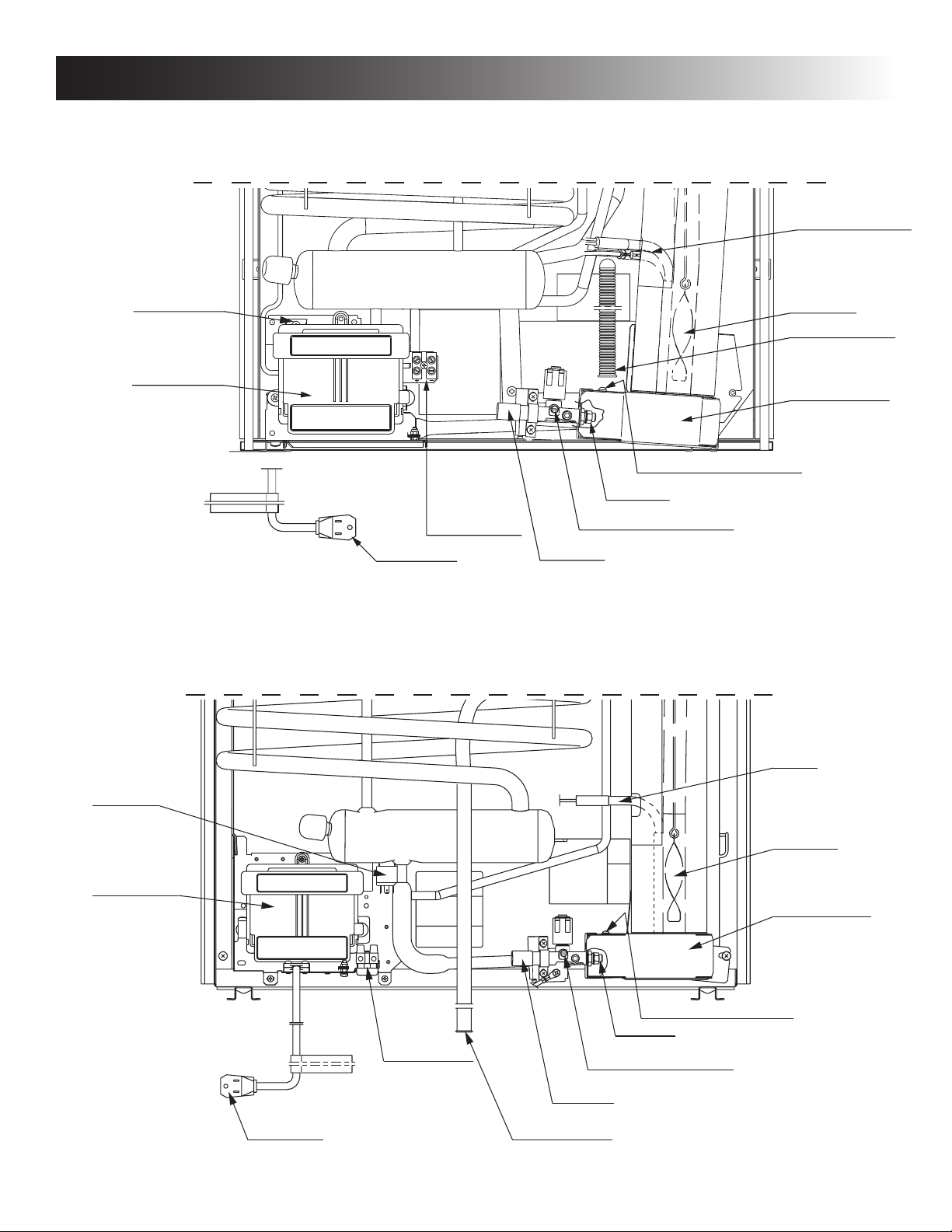
APPENDIX B - REARVIEW EQUIPMENT
RM2351 & RM2354
1 heater - RM2351
2 heaters - RM2354
Relay
Power module
cover
Burner jet
12 V DC
Terminal block
Flexible cord
Manual gas shutoff valve
Inlet fitting
RM2451, RM2454, RM2551 & RM2554
Flue baffle
Drain water hose
Protection cover
Screw for protection cover
Relay,
3-way only
Power module
cover
Flexible cord
12V DC
12 volt
Terminal block
Heater
Flue baffle
Protection cover
Screw for protection cover
Burner jet
Manual gas shutoff valve
Inlet fitting
Drain water hose
17
Page 18
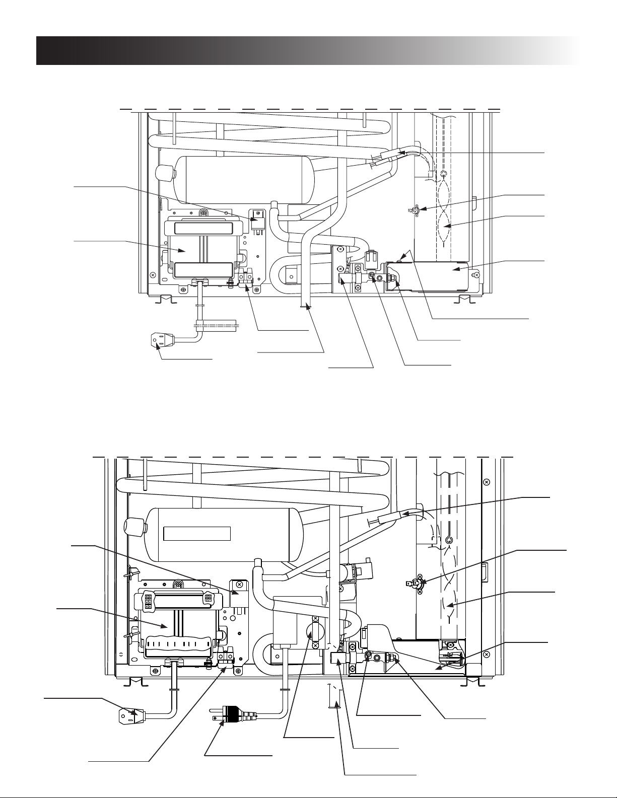
APPENDIX B - REARVIEW EQUIPMENT
DM2652, DM2662, DM2663, DM2852, DM2862 & NDM1062
Relay,
3-Way only
Power module
cover
12V DC
Heater(s)
Thermofuse
Flue baffle
Protection
cover
Relay
Power
Module
Cover
Flexible cord
12 volt DC
Terminal block
Drain water hose
Inlet fitting
Shown without Secondary Burner Housing for illustrative purposes only.
NDM1062 (WITH ICE MAKER)
Screw for protection cover
Burner jet
Manual gas
shutoff valve
Heater
Thermofuse
Flue Bafe
Flexible Cord
12V DC
Terminal Block
12V DC
Flexible Cord
(Icemaker)
Manual Gas
Shutoff Valve
Burner Jet
Thermostat
Inlet Fitting
18
Shown without Secondary Burner Housing for illustrative purposes only.
Drain Water Hose
Protection
Cover
Page 19
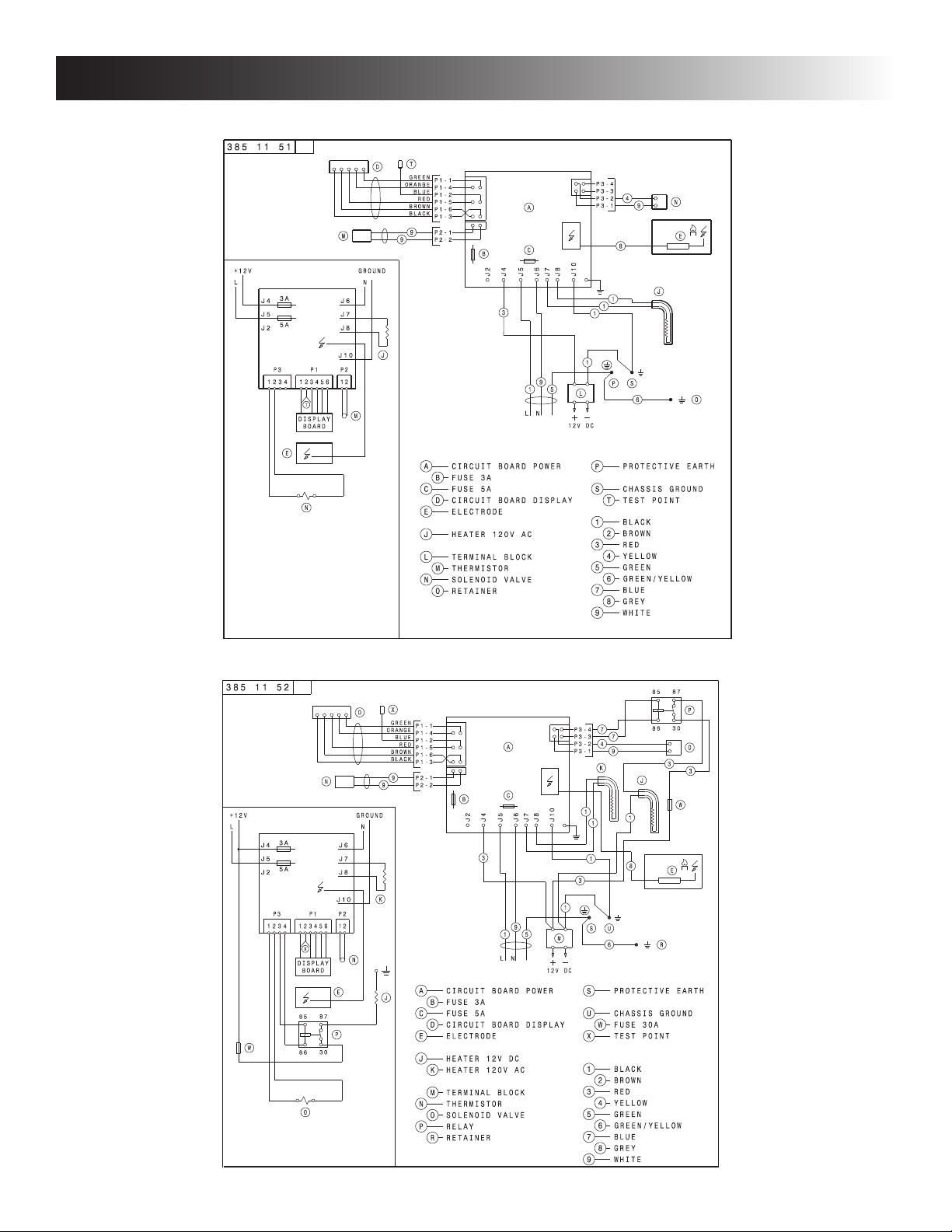
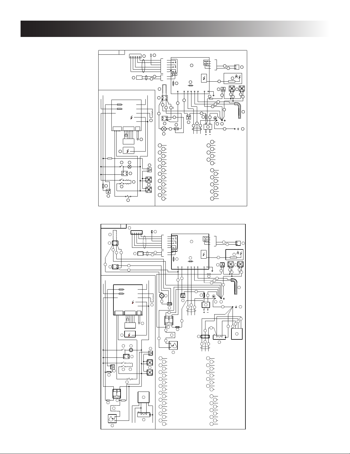
APPENDIX C - WIRING DIAGRAM
RM2351, RM2451 & RM2551
RM2354, RM2454 & RM2554
19
Page 20
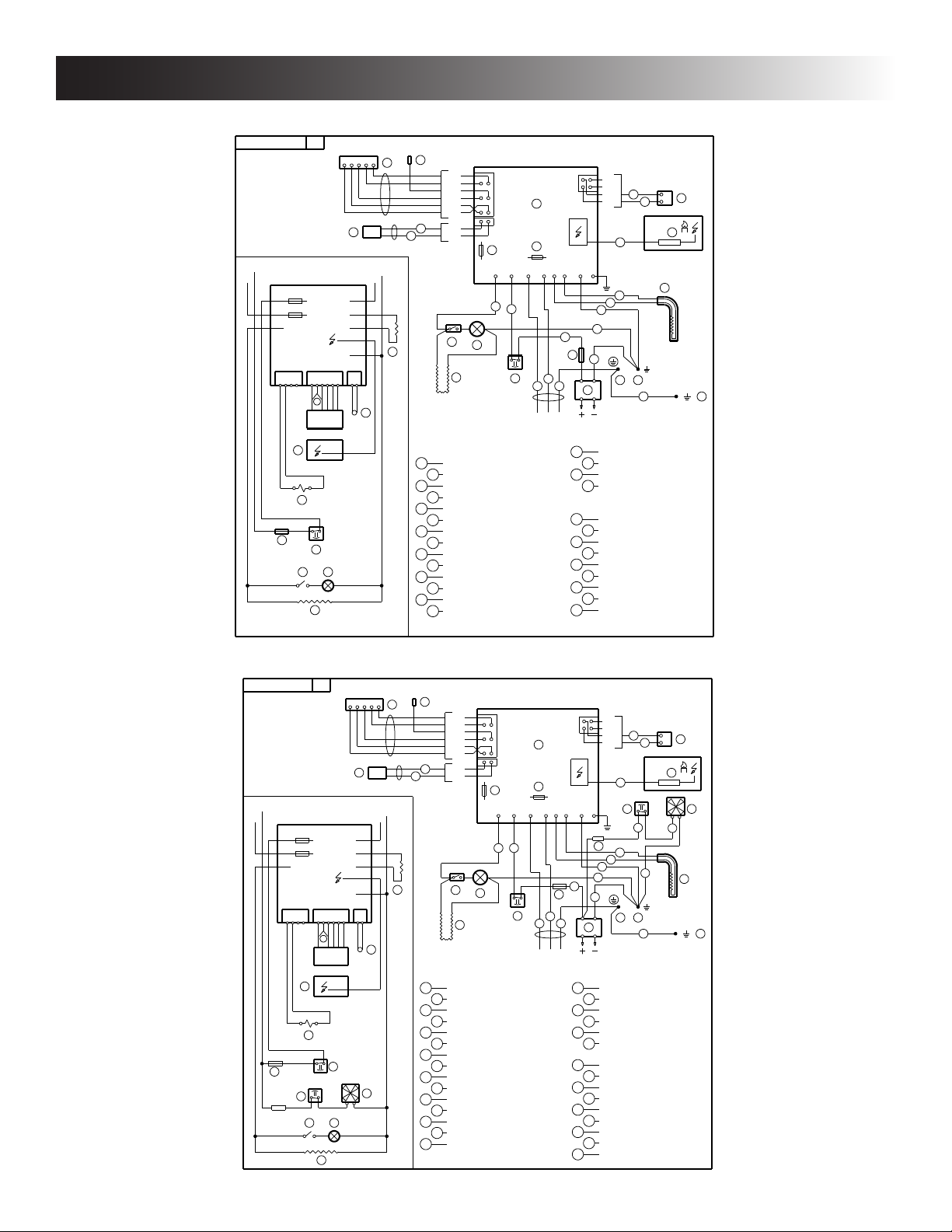
APPENDIX C - WIRING DIAGRAM
DM2652, DM2662, DM2852 & DM2862 (NO FAN) WITH AND WITHOUT ICE MAKER
385 14 82
T
D
GREEN
P1−1
ORANGE
P1−4
BLUE
P1−2
RED
P1−5
L
J 4
J 5
J 2
1 2 3 4 1 2 3 4 5 6 1 2
BROWN
P1−6
BLACK
P1−3
P2−1
M
GROUND+12V
N
3 A
5 A
P3
P1 P2
T
DISPLAY
BOARD
J 6
J 7
J 8
J10
M
9
P2−2
9
H
J
G
K
A
C
B
J 4
J 5
J 2
3
J 6
3
F
195
L N
P3−4
P3−3
P3−2
4
P3−1
8
J 8
J 7
J10
1
1
1
1
3
U
1
P S
L
12V D C
N
9
E
J
6 O
E
N
U
F
GH
K
A
CIRCUIT BOARD POWER S
B
FUSE 3A
C
FUSE 5A
D
CIRCUIT BOARD DISPLAY
E
ELECTRODE
THERMOFUSE
F
LAMP
G
SWITCH LAMP
H
J HEATER 120V AC
K
HEATING CABLE
L
TERMINAL BLOCK
M
THERMISTOR
N
SOLENOID VALVE
RETAINER
O
PROTECTIVE EARTH
P
CHASSIS GROUND
TEST POINT
T
U
THERMAL FUSE
BLACK1
BROWN
2
RED
3
4
YELLOW
5
GREEN
6
GREEN/YELLOW
BLUE
7
GREY
98WHITE
DM2652, DM2662, DM2852 & DM2862 (ONE FAN) WITH AND WITHOUT ICE MAKER
385 14 84
T
D
GREEN
L
J 4
J 5
J 2
1 2 3 4 1 2 3 4 5 6 1 2
P1−1
ORANGE
P1−4
BLUE
P1−2
RED
P1−5
BROWN
P1−6
BLACK
P1−3
P2−1
M
GROUND+12V
3 A
5 A
P3
P1 P2
T
DISPLAY
BOARD
J 6
J 7
J 8
J10
M
9
P2−2
9
N
J
H
G
K
A
C
B
J 4
J 5
J 2
3
J 6
3
F
195
L N
P3−4
P3−3
P3−2
4
P3−1
8
J 8
J 7
3
Y
12V D C
U
J10
X
1
1
1
1
1
P S
L
N
9
E
3
3
1
6 O
V
J
E
N
Y
3 A
F
U
V
GH
K
A
CIRCUIT BOARD POWER
B
FUSE 3A
C
FUSE 5A
D
CIRCUIT BOARD DISPLAY
E
ELECTRODE
THERMOFUSE
F
LAMP
G
SWITCH LAMP
H
J HEATER 120V AC
K
HEATING CABLE
L
TERMINAL BLOCK
M
THERMISTOR
N
SOLENOID VALVE
RETAINER
O
PROTECTIVE EARTHP
CHASSIS GROUND
S
TEST POINT
T
U THERMOFUSE
V
FAN
X
FUSE 3A
Y THERMAL FUSE
BLACK1
BROWN
2
RED
3
YELLOW
4
5
GREEN
6
GREEN/YELLOW
BLUE
7
GREY
98WHITE
20
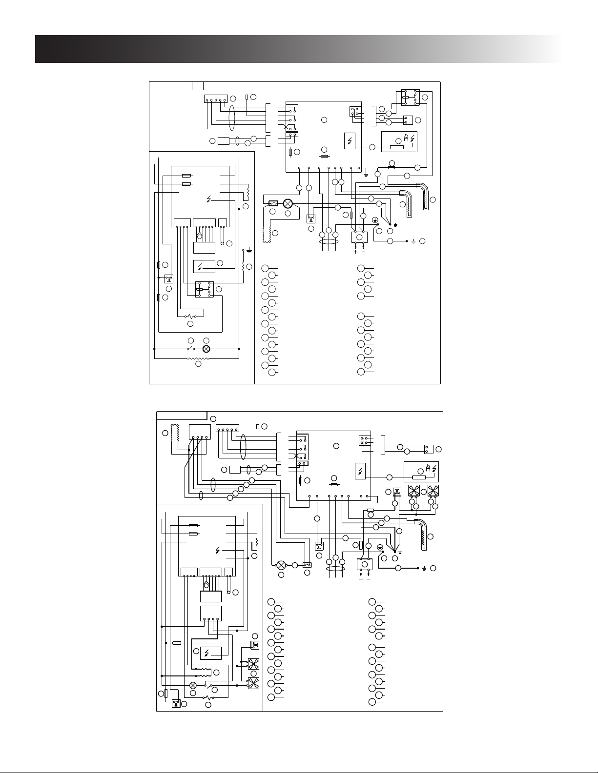
Page 21
U
3
12V D C
H
A
B
C
D
E
F
G
CIRCUIT BOARD DISPLAY
FUSE 5A
SWITCH LAMP
L
K
HEATER 120V AC
LAMP
MNTHERMOFUSE
PROTECTIVE EARTH
R
TEST POINT
FANS
CIRCUIT BOARD POWER
S
TERMINAL BLOCK
CHASSIS GROUND
T
H
FUSE 3A
ELECTRODE
THERMISTOR
J HEATING CABLE
N
GROUND+12V
L
1 2 3 4 1 2 3 4 5 6 1 2
DISPLAY
BOARD
3 A
J 4
J 5
J 2
J 6
J 7
J 8
L
P3
J10
P1 P 2
T
5 A
D
J
CLC
J2
J10
P1−1
P1−4
P3−4
P3−3
P3−1
A
C
B
J5J8J7
J6
P3−2
T
P1−5
P1−2
P1−6
P1−3
L
P2−1
P2−2
9
9
GREEN
ORANGE
BLUE
RED
BROWN
BLACK
3
L N
H
195
K
1
O
6 P
R S
4
9
GND
LAC
+12V
F
G
1
8
3
3
1
8
LAC
+12V
GND
CLC
G
O
J
E
F
U THERMOFUSE
E
8
J4
M
3
3
N
1
1
1
1
OPSOLENOID VALVE
RETAINER
M
N
3
1 1
3 A
V
FUSE 3AV
U
GREEN/YELLOW
GREEN
7
6
5
4
3
2
1 BLACK
BROWN
RED
BLUE
GREY
WHITE
8
9
YELLOW
THERMAL FUSEY
Y
Y
385 14 04
APPENDIX C - WIRING DIAGRAM
DM2663 (NO FAN) WITHOUT ICE MAKER
385 14 83
X
D
GREEN
P1−1
ORANGE
P1−4
BLUE
P1−2
+12V
L
Y
F
W
3 A
J 4
J 5
5 A
J 2
P1 P 2
P3
1 2 3 4 1 2 3 4 5 6 1 2
X
DISPLAY
BOARD
8 7
8 5
3 0
8 6
O
GH
L
RED
P1−5
BROWN
P1−6
BLACK
P1−3
P2−1
GROUND
N
N
9
P2−2
9
K
H
G
L
J
A
CIRCUIT BOARD POWER
FUSE 3A
B
C
FUSE 5A
D
CIRCUIT BOARD DISPLAY
ELECTRODE
E
THERMOFUSE
F
LAMP
G
H
SWITCH LAMP
HEATER 12V DC
J
K
HEATER 120V AC
HEATING CABLE
L
M
TERMINAL BLOCK
N
THERMISTOR
O
SOLENOID VALVE
RELAY
P
R
RETAINER
N
J 6
J 7
J 8
J10
E
P
A
C
B
J 4
J 5
J 2
3
J 7
J 6
J 8
1
1
3
3
Y
F
195
L N
J10
1
M
12 V D C
S
W
Y
3
5
7
98WHITE
P3−4
7
P3−3
7
P3−2
4
P3−1
9
E
8
W
3
1
1
1
S U
6 R
PROTECTIVE EARTH
CHASSIS GROUND
U
FUSE 30A
TEST POINT
X
THERMAL FUSE
BLACK1
BROWN
2
RED
YELLOW
4
GREEN
6
GREEN/YELLOW
BLUE
GREY
8 7
8 5
P
3 0
8 6
O
3
3
K
J
NDM1062 (STAINLESS STEEL DOORS)
21
Page 22
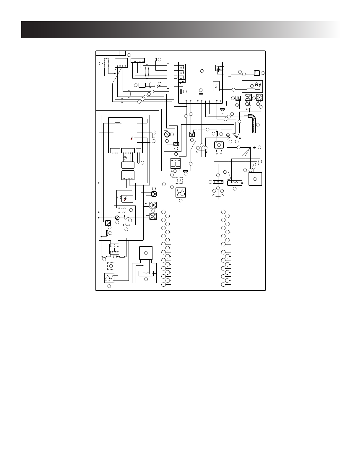
APPENDIX C - WIRING DIAGRAM
NDM1062 (STAINLESS STEEL DOORS & ICE MAKER)
385 14 44
J
L
J4
J5
J2
U
Y
8 6
3 0
AG
AE
°
C
AF
D
+12V
CLC
GND
LAC
L
3 A
5 A
P1 P2
P3
1 2 3 4 1 2 3 4 5 6 1 2
T
DISPLAY
BOARD
LAC
+12V
GND
CLC
E
J
G
F
O
8 5
8 7
AD
3 A
N
L
3
1
J6
J7
J8
J10
L
M B 4
3
GROUND+12V
AA
AB
8
N
GROUND
T
GREEN
ORANGE
BROWN
BLACK
9
9
1
H
M
N
P1−1
P1−4
BLUE
P1−2
RED
P1−5
P1−6
P1−3
P2−1
P2−2
B
J2
3
F
8
G
1
8 6
8 5
8 7
3 0
AD
AG
3
AE
1
1
°
C
AF
A
CIRCUIT BOARD POWER
B
FUSE 3A
C
FUSE 5A
D
CIRCUIT BOARD DISPLAY
E
ELECTRODE
LAMP
F
SWITCH LAMP
G
HEATER 120V AC
H
J HEATING CABLE
K
TERMINAL BLOCK
L
THERMISTOR
MNTHERMOFUSE
FANS
OPSOLENOID VALVE
RETAINER
RSPROTECTIVE EARTH
CHASSIS GROUND
TUTEST POINT
THERMOFUSE
A
C
J4
J5J8J7
J6
3
3
U
195
L N
3
AC
J10
Y
K
12V D C
6
159
L N
120 V AC
P3−4
P3−3
P3−2
P3−1
8
M
V
1
1
1
1
R S
9
M B 4
PROTECTIVE EARTH
V
Y
CHASSIS GROUND
AA
ICEMAKER
AB
WATER VALVE
TERMINAL BLOCK
AC
AD
RELAY
AE
HEATING CABLE
THERMOSTAT
AF
AG
FUSE 4A
BLACK1
BROWN
2
RED
3
YELLOW
4
5
GREEN
6
GREEN/YELLOW
BLUE
7
GREY
98WHITE
4
9
3
1
6 P
6
AB
E
3
1 1
6
O
N
3
H
9
1
2
AA
22
Page 23
W
3
12V D C
H
A
B
C
D
E
F
G
CIRCUIT BOARD DISPLAY
FUSE 5A
SWITCH LAMP
L
K
HEATER 120V AC
LAMP
MNTHERMOFUSE
FANS
CIRCUIT BOARD POWER
TERMINAL BLOCK
H
FUSE 3A
ELECTRODE
THERMISTOR YELLOW
98WHITE
GREY
BLUE
RED
BROWN
BLACK1
2
3
4
5
6
7
J HEATING CABLE
GREEN
GREEN/YELLOW
N
GROUND+12V
L
1 2 3 4 1 2 3 4 5 6 1 2
DISPLAY
BOARD
3 A
J4
J5
J2
J6
J7
J8
L
P3
J10
P1 P2
Z
5 A
D
J2
P1−1
P1−4
P3−4
P3−3
P3−1
A
C
B
J5J8J7
J6
P3−2
Z
P1−5
P1−2
P1−6
P1−3
L
P2−1
P2−2
9
9
GREEN
ORANGE
BLUE
RED
BROWN
BLACK
3
L N
H
195
K
1
O
6 P
S X
4
9
F
G
8
O
E
J
T
3
U
3
8
O SOLENOID VALVE
31
1
J
U
FG
T
J10
E
8
J4
333
1 1
M N
1
1
1
1
M
N
P RETAINER
3 A
Y
THERMAL FUSER
S PROTECTIVE EARTH
TEST POINTZ
FUSE 3AY
CHASSIS GROUNDX
W
SWITCH L.A.CU
THERMOFUSE
T SWITCH
R
W
R
385 14 05
APPENDIX C - WIRING DIAGRAM
NDM1062 (DOOR INSERT PANELS)
NDM1062 (DOOR INSERT PANELS & ICE MAKER)
385 14 52
J
T
3
U
L
R
86
30
AG
°
C
AF
D
1
31
L
8
3
3 A
J4
J5
5 A
J2
P3
1 2 3 4 1 2 3 4 5 6 1 2
W
AD
AE
P1 P 2
Z
DISPLAY
BOARD
E
FG
U
J
T
O
85
87
3 A
N
L
J6
J7
J8
J10
M B 4
Z
GREEN
P1−1
ORANGE
P1−4
BLUE
P1−2
RED
P1−5
BROWN
P1−6
BLACK
P1−3
P2−1
9
P2−2
9
GROUND+12V
N
F
8
H
L
M
N
AA
AB
GROUND
G
1
86
85
87
30
AD
3
AE
1
1
°
AF
CIRCUIT BOARD POWER
A
FUSE 3A
B
C
FUSE 5A
D
CIRCUIT BOARD DISPLAY
ELECTRODE
E
F
LAMP
SWITCH LAMP
G
H
HEATER 120V AC
J HEATING CABLE
TERMINAL BLOCK
K
THERMISTOR
L
MSTHERMOFUSE
N FANS
O SOLENOID VALVE
P RETAINER
R THERMAL FUSE
PROTECTIVE EARTH
T SWITCH
U SWITCH L.A.C
W THERMOFUSE
A
C
B
J2
J5J8J7
J6
J4
3
3
W
195
L N
3
AG
C
J10
Y
3
R
1
K
12V D C
6
AC
159
L N
120 V AC
X CHASSIS GROUND
Z
AB
AD
AF
P3−4
P3−3
P3−2
4
P3−1
8
M
3
1
1
1
1
S X
6 P
9
M B 4
AB
FUSE 3AY
TEST POINT
AA
ICEMAKER
WATER VALVE
AC
TERMINAL BLOCK
RELAY
AE
HEATING CABLE
THERMOSTAT
AG
FUSE 4A
BLACK1
BROWN
2
RED
3
YELLOW
4
5
GREEN
6
GREEN/YELLOW
BLUE
7
GREY
98WHITE
9
6
3
1 1
6
O
E
N
3
H
9
1
2
AA
23
Page 24
APPENDIX D - CONSUMER SUPPORT
Dometic website www.DometicUSA.com
Please visit our website for information and news about Dometic products. Our website provides information on product
care and warranties. You can also download product literature, including manuals and brochures.
Service and spare parts www.eDometic.com
For service and spare parts, please contact Service Center Assistance. Please see the front page of this manual - or -
visit our Dometic website to nd a Dometic Service Center near you.
Contact us www.DometicUSA.com
For contact information, please see the front page of this manual - or - visit our Dometic website.
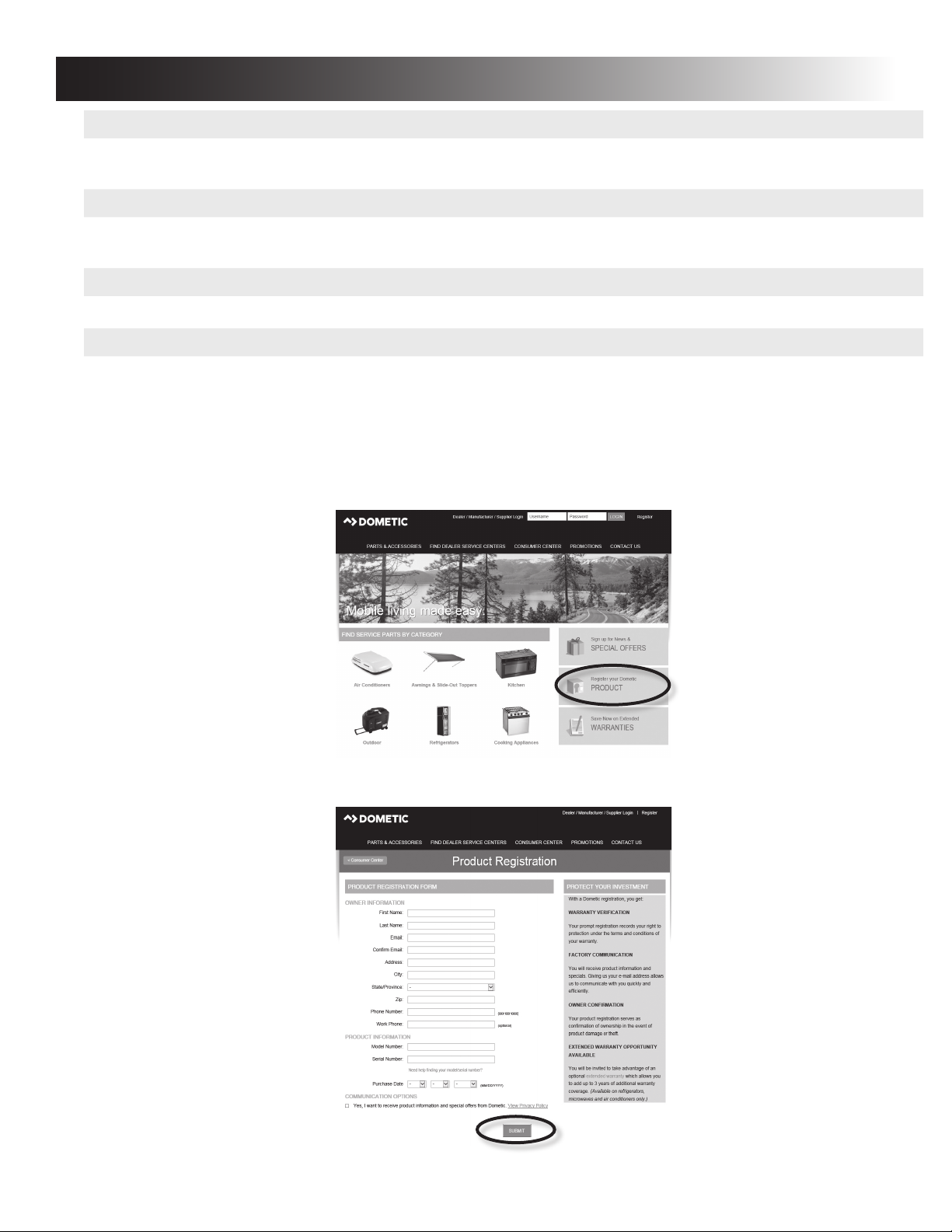
Register product www.eDometic.com
Timely registration allows for enhanced communication and service under the terms of your warranty. Please see
“Appendix E - Dometic Warranty” on page (25).
To register your product, ll in the pre-printed registration card on the last page of this manual, or register on-line at
www.eDometic.com.
TO REGISTER ON-LINE:
1. Access www.eDometic.com then click “Register your Dometic PRODUCT.”
2. Complete the on-line form, then click “SUBMIT”.
24
Page 25

APPENDIX E - DOMETIC WARRANTY
LIMITED TWO-YEAR WARRANTY (DOMETIC REFRIGERATORS)
THE SELLER NAMED BELOW MAKES THE FOLLOWING WARRANTY WITH RESPECT TO THE DOMETIC PRODUCT:
1. This Warranty is made only to the rst purchaser (hereinafter referred to as the “Original Purchaser”), who acquires the Dometic Product for his or her own use
and when the Dometic Product is installed and operated within the continental United States and Canada.
2. WARRANTY PERIOD: This Warranty will be in effect for two (2) years from the date of purchase by the Original Purchaser. The Original Purchaser should
retain a copy of the dated bill of sale as evidence of the date of purchase.
3. WARRANTY: This Warranty covers labor, specied parts, and freight. The Dometic Product shall be free from defects in material and workmanship at the
time of sale and under normal use. All Dometic Products (except those specically built for commercial use) are warranted only when installed per the Seller’s
installation instructions on vehicles built to R.V.I.A. A119-2 and C.R.V.A. Z-240 Standards. This Warranty does NOT cover conditions unrelated to the material
and workmanship of the Dometic Product. Such unrelated conditions include, but are not limited to: (a) damage not reported within 10 days of ownership; (b)
faulty installation or installation that does not comply with the Seller’s instructions or R.V.I.A. and C.R.V.A. standards, and any damage resulting from such; (c)
damage or failure caused by installation of accessories not manufactured and marketed by the Seller or any non-Dometic parts that are installed as replacement
parts; (d) the need for normal maintenance and any damage resulting from the failure to provide such maintenance; (e) failure to follow Seller’s instructions for
use of this Dometic Product; (f) ame outage due to blow out or high altitude; (g) reduced performance due to high altitude; (h) radio frequency interference
(RFI) or electromagnetic interference (EMI); (i) 12 VDC system chassis ground decay and corrosion; (j) puncture of foam cabinet or vacuum insulated panels
after acknowledged receipt; (k) animal or insect inltration which damages unit or inhibits performance; (l) any accident to, or misuse of, any part of the
Dometic Product and any alteration by anyone other than the Seller or its authorized representative; and (m) normal wear.
4. WARRANTY COVERS DOMETIC COMPONENT PARTS: Major components (cooling unit, LP gas valve, burner, burner housing, electronic display,
electronic module, evaporator ns, foam integrity, frame, thermistor, spark probe, ignition wire, ice maker compressor, second absorption loop, display
escutcheon, lower toe plate, humidity switch, frame heater mullion, ice maker mullion) are covered for labor, parts and freight for two (2) years from date
of purchase. All other components that fail must be reported within the rst 90 days of ownership in order to receive warranty coverage for labor, parts and
freight.
5. The Original Purchaser must provide preventative maintenance on a yearly basis, beginning at the rst anniversary of the date of purchase. The Original
Purchaser must keep a record of the preventative maintenance to keep the warranty in effect. Failure of the Original Purchaser in providing this annual
maintenance may void the warranty. The preventative maintenance must be performed at a Dometic Authorized Service Center/Dealer. The required
preventative maintenance is an inspection, cleaning and full diagnostics performed on the entire electronic system, burner assembly, wiring and cooling unit. A
copy of the receipt covering the maintenance checks must accompany the warranty claim during the second year of ownership. The cost of this preventative
maintenance is the Original Purchaser’s responsibility and the preventative maintenance should take about one hour.
6. WARRANTY REMEDY: In order to obtain the benets of this Warranty, the Original Purchaser has the following two options during the WARRANTY
PERIOD:
a. Preferred option: Deliver the Dometic Product for inspection to the nearest Authorized Dometic Service Center during the Warranty Period. To obtain the
location of the nearest Authorized Dometic Service Center, refer to https://www.dometic.com/en-us/us/nd-a-dealer. The Authorized Dometic Service
Center will work with the Seller to obtain Warranty coverage if a Seller defect is identied. CONFIRM THE SERVICE CENTER IS AN AUTHORIZED
DOMETIC SERVICE CENTER. DO NOT PAY THE SERVICE CENTER FOR WARRANTY REPAIRS.
b. Second option: If it is not feasible under the circumstances to deliver the Dometic Product to an Authorized Dometic Service Center, please call 1-800-
544-4881 for additional Warranty assistance. Seller prefers option a. rst and only option b. if option a. is determined not to be feasible under the
circumstances.
7. Any item returned in the manner described in paragraph 6 will be examined by the Authorized Dometic Service Center. If it is found that the returned item was
defective in material and workmanship at the time of sale, the Authorized Dometic Service Center will contact the Seller for Warranty coverage. The Seller
shall, at Dometic’s sole option, repair or replace the Dometic Product, or refund Original Purchaser’s purchase price. If the Seller determines that repairs to the
Dometic Product are to be made, then only authorized Dometic parts will be used.
8. The Seller does not authorize any person or company to create any Warranty obligations or liability on its behalf. This Warranty is not extended by the length of
time which you are deprived of the use of the Dometic Product.
9. IN NO EVENT SHALL SELLER BE LIABLE FOR EITHER INCIDENTAL OR CONSEQUENTIAL DAMAGES. THIS INCLUDES ANY DAMAGE
TO ANOTHER PRODUCT OR PRODUCTS RESULTING FROM SUCH A DEFECT. SOME STATES DO NOT ALLOW THE EXCLUSION OR
LIMITATION OF INCIDENTAL OR CONSEQUENTIAL DAMAGES, SO THE ABOVE LIMITATIONS MAY NOT APPLY TO YOU.
10. ANY IMPLIED WARRANTY, INCLUDING THE IMPLIED WARRANTY OF MERCHANTABILITY AND FITNESS FOR ANY PURPOSE, IS
LIMITED TO THE DURATION OF THIS LIMITED WARRANTY. SOME STATES DO NOT ALLOW LIMITATIONS ON HOW LONG AN
IMPLIED WARRANTY LASTS, SO THE ABOVE LIMITATION MAY NOT APPLY TO YOU.
11. THIS WARRANTY GIVES SPECIFIC LEGAL RIGHTS, YOU MAY ALSO HAVE OTHER RIGHTS WHICH VARY FROM STATE TO STATE.
No action to enforce this Warranty shall be commenced later than ninety (90) days after the expiration of the Warranty Period. Claims must be submitted in
writing to the Dometic Warranty Department.
12. The Seller reserves the right to change the design of any Dometic product without notice and with no obligation to make corresponding changes in Dometic
products previously manufactured.
PROTECTION FOR YOUR NEW INVESTMENT
We appreciate that you have chosen to purchase a
Dometic product for your recreational vehicle and we want to help
you protect this wise investment. We at Dometic, back our products with one of the most comprehensive warranties in the industry.
Register your product online at: www.eDometic.com.
25
Dometic Corporation
Warranty Department
1120 North Main Street
Elkhart, Indiana 46514
1-574-294-2511
Register Your Product @
www.eDometic.com
Form No. 3316980.000 (10/17)
(French 3316985.000)
©2017 Dometic Corporation
LaGrange, IN 46761
Page 26

APPENDIX F - MAINTENANCE SCHEDULE
REFRIGERATOR OWNER MAINTENANCE YEARLY RECORD
Customer Name: Model No.: Date of Purchase:
Address: Serial No.:
City: State: Zip Code:
Phone:
FIRST YEAR
Date:
Dealership:
Address:
City:
State: Zip:
Phone:
Technician:
Cleaned Burner Assembly: Yes / No
Cleaned/Check All Terminals Connections: Yes / No
Cleaned/Inspect All Ground Connections: Yes / No
Inspect and Test Door Seals: Yes / No
Inspect and Tighten LP Lines: Yes / No
Power Ventilator Installed: Yes / No
Gas Safety Shutdown in 45 seconds: Yes / No
SECOND YEAR
Date:
Dealership:
Address:
City:
State: Zip:
Phone:
Technician:
Cleaned Burner Assembly: Yes / No
Cleaned/Check All Terminals Connections: Yes / No
Cleaned/Inspect All Ground Connections: Yes / No
Inspect and Test Door Seals: Yes / No
Inspect and Tighten LP Lines: Yes / No
Power Ventilator Installed: Yes / No
Gas Safety Shutdown in 45 seconds: Yes / No
ACTUAL SPEC. RANGE
Electrode Gap 3/16”
Thermistor Reading 7-10,000 ohms @ 32°
D/C Voltage 9.5 to 15 volts D/C
A/C Voltage 120 Volts ± 10%
Thermocouple Reading 25-35 Millivolts
Delay Between Modes Approx. 5 seconds
ICE MAKER MODELS
Inspect Water Valve and All Connections: Yes / No
Inspect Heat Tape Switch for Proper
Operation: Yes / No
26
 Loading...