

Page 1
REFRIGERATION
REFRIGERATOR
RM2351, DM2652, DM2662, DM2663, DM2682, DM2852, DM2862 DM2882, RM2354, RM2551, DM2683,
RM3962, RM2554, RM3762, RM2451, RM1350, RM2454, DM2672, DM2872, RM1350SL
DM & RM Refrigerators
EN
Installation Manual
WARNING: Improper installation, adjustment,
alteration, service or maintenance can
cause injury or property damage. Refer to
this manual. For assistance or additional
information consult a qualified installer,
service agency or the gas supplier.
FIRE OR EXPLOSION HAZARD
If you smell gas:
1. Open windows.
2. Do not attempt to light appliance.
3. Do not touch electrical switches.
4. Extinguish any open flame.
5. Shut off fuel supply.
6. Evacuate immediately and call emergency
services.
Failure to follow these instructions could result
in fire or explosion, which could cause property
damage, personal injury, or death.
Page 2

Refrigerator
NORTH AMERICAN ADDRESS INFORMATION
USA & CANADA
Service Office
Dometic Corporation
1120 North Main Street
Elkhart, IN 46514
REVISION F | Form No. 3313238.036 7/18 | ©2018 Dometic Corporation
Read these instructions carefully. These instructions MUST stay with this product.
Service Center & Dealer Locations
Visit: www.dometic.com
CONTENTS
1 Explanation of symbols and safety instructions ................................................ 3
2 General information ..................................................................... 4
3 Intended use ........................................................................... 4
4 Specifications .......................................................................... 5
5 Prepare for installation .................................................................. 14
6 Installation ............................................................................ 24
7 Disposal .............................................................................. 43
EN
2
Page 3

Refrigerator
1 EXPLANATION OF SYMBOLS AND SAFETY INSTRUCTIONS
This manual has safety information and instructions to help you eliminate or reduce the risk of accidents
and injuries.
1.1 Recognize safety information
This is the safety alert symbol. It is used to alert you to potential physical injury hazards. Obey all safety
messages that follow this symbol to avoid possible injury or death.
1.2 Understand signal words
A signal word will identify safety messages and property damage messages, and will indicate the degree or level
of hazard seriousness.
indicates a hazardous situation that, if not avoided, could result in death or serious injury.
indicates a hazardous situation that, if not avoided, could result in minor or moderate injury.
is used to address practices not related to physical injury.
indicates additional information that is not related to physical injury.
I
1.3 Supplemental directives
Read and follow all safety information and instructions to avoid possible injury or death.
Read and understand these instructions before installation of this product.
Incorrect installation of this product can lead to serious injury.
The installation must comply with all applicable local or national codes, including the latest edition of the
following standards:
This appliance is certified under the latest edition of ANSI Z21.19, CSA 1.4 Refrigerators using gas fuel. The
installation must conform with local codes, or in absence of local codes, the following standards as applicable:
U.S.A.
• ANSI/NFPA70, National Electrical Code (NEC)
• ANSI/NFPA 1192, Recreational Vehicles Code
• Title 24 CFR, Part 3280, Manufactured Home
Construction and Safety Standard
• National Fuel Gas Code, ANSI Z223.1/NFPA 54
Canada
• CSA C22.1, Parts l & ll, Canadian Electrical Code
• CSA Z240 RV Series, Recreational Vehicles
• CSA Z240.4, Gas-Equipped Recreational Vehicles
and Mobile Housing
• CSA B149.1, Natural Gas and Propane Installation
Code CERTIFICATION
1.4 General safety messages
Failure to obey the following warnings could result in death or serious injury:
• This product must be installed by a qualified service technician.
• Any modifications or deviations:
– Can lead to carbon monoxide leaking into the living area.
– Can reduce cooling performance and/or result in damage to the refrigerator.
– Will void agency certifications.
– Will void refrigerator warranty.
• ELECTRICAL SHOCK HAZARD. This product is equipped with a three-prong (grounding) plug for protection
against shock hazards. This product should be plugged directly into a three-prong receptacle that provides
grounding in compliance with all applicable electrical codes. Do not cut or remove grounding prong from
plug.
3
EN
Page 4

Refrigerator
• FIRE OR EXPLOSION HAZARD:
– Before refueling or parking near a gasoline pump, make sure all LP gas appliances (vented to the outside of
RV) are shut off . Otherwise, fumes from gasoline pumps could come into contact with an LP gas appliance
burner flame and ignite.
– Do not store or use gasoline, oil- or gasoline-soaked rags, or other flammable vapors and liquids in the
service area behind the refrigerator or in the vicinity of this or any other gas appliance.
• ABSORPTION-COOLING SYSTEMS: FIRE, BURN, OR INHALATION HAZARD. Do not fracture or puncture
cooling unit. The cooling unit is under pressure and contains ammonia, sodium chromate, and other
chemicals. Repeated or prolonged exposure to sodium chromate could cause organ damage or cancer.
Exposure to a high concentration of ammonia refrigerant could cause pulmonary edema (fluid in lungs);
chemical burns to eyes, lungs, and skin; and could cause a fire (when exposed to open flame).
• COMPRESSOR-COOLING SYSTEMS: FIRE, FROSTBITE, OR INHALATION HAZARD. Do not fracture or
puncture cooling unit. The cooling unit is under pressure and contains tetrafluoro ethane refrigerant, and may
contain other chemi cals. Contact with liquid refrigerant could cause irritation or frostbite to eyes and skin.
Exposure to a high concentration of refrigerant could cause cardiac arrhythmia (irregular heartbeat). A high
concentration of refrigerant could cause a fire (when exposed to open flame).
• FIRE OR INHALATION HAZARD. If the refrigerator stops working and/or it emits an ammonia smell,
immediately turn refrigerator off (if it is safe to do so), leave the vicinity, and contact a qualified Service Center.
• LIFTING HAZARD. Use proper liing technique and control when liing the product.
2 GENERAL INFORMATION
Optional Parts* Reference Number
Innovator Refrigerator Ventilation
System
Z-bracket 3103812.xxx
*Available as accessory (not included)
3108705.751, 3108705.744
3 INTENDED USE
The DM and RM refrigerators are designed and intended for use only inside a recreational vehicle (hereinafter
referred to as “RV”) for which it is supplied. Use the instructions to ensure correct installation of the refrigerator.
Dometic Corporation accepts no liability for damage in the following cases:
• Faulty assembly or connection.
• Damage to the product resulting from mechanical influences and excess voltage.
• Alterations to the product without expressed permission from Dometic Corporation.
• Use for purposes other than those described in the operating manual.
Dometic Corporation reserves the right to modify appearances and specifications without notice.
EN
4
Page 5
Refrigerator
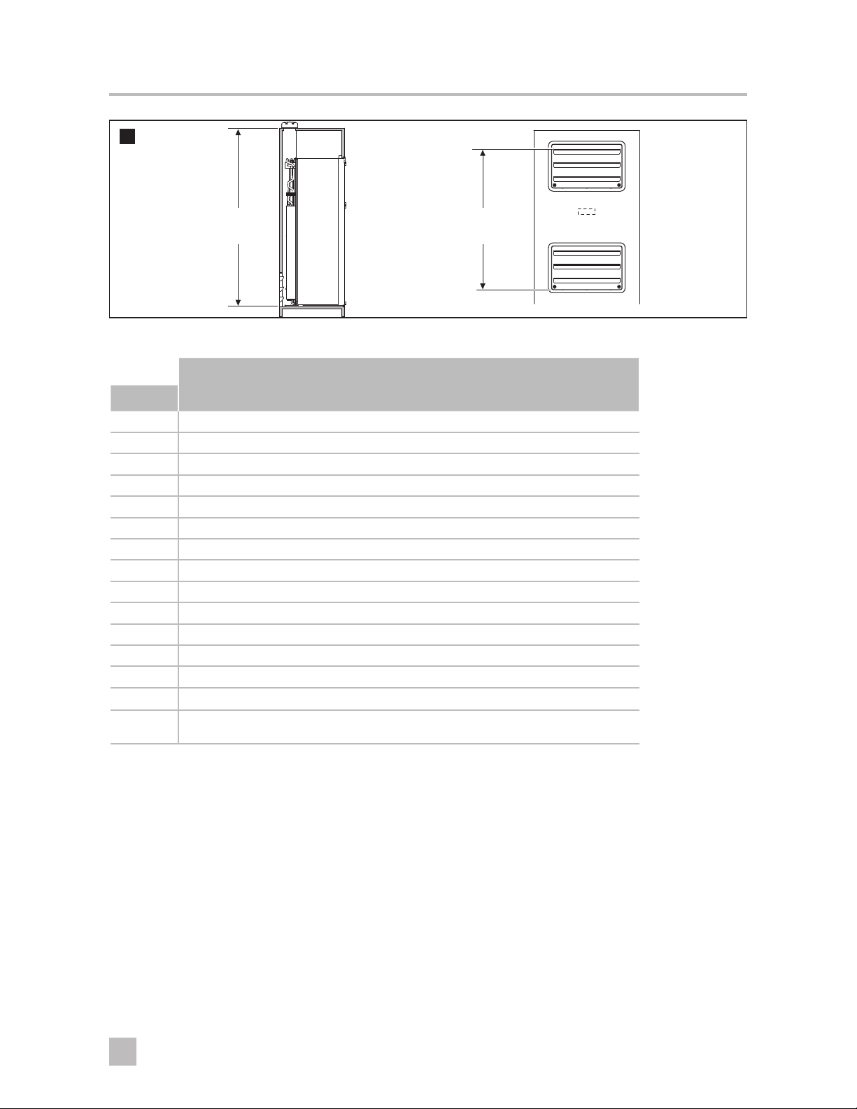
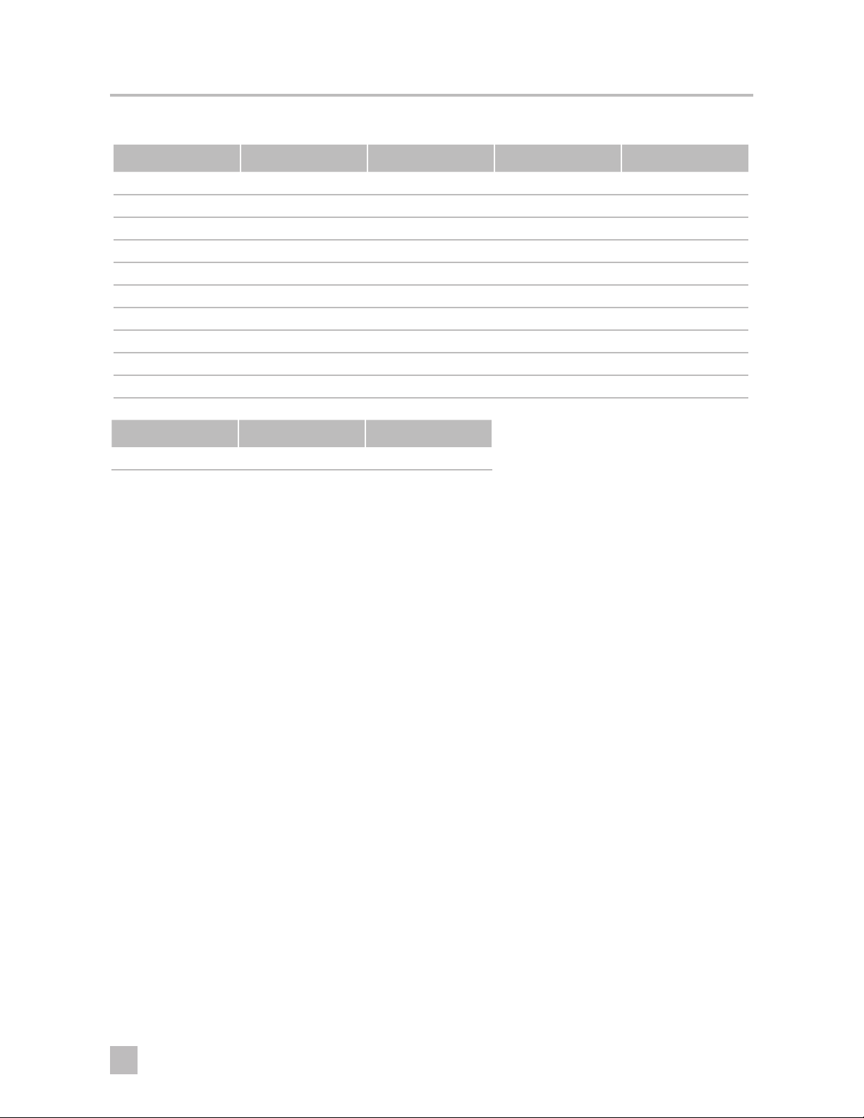
4 SPECIFICATIONS
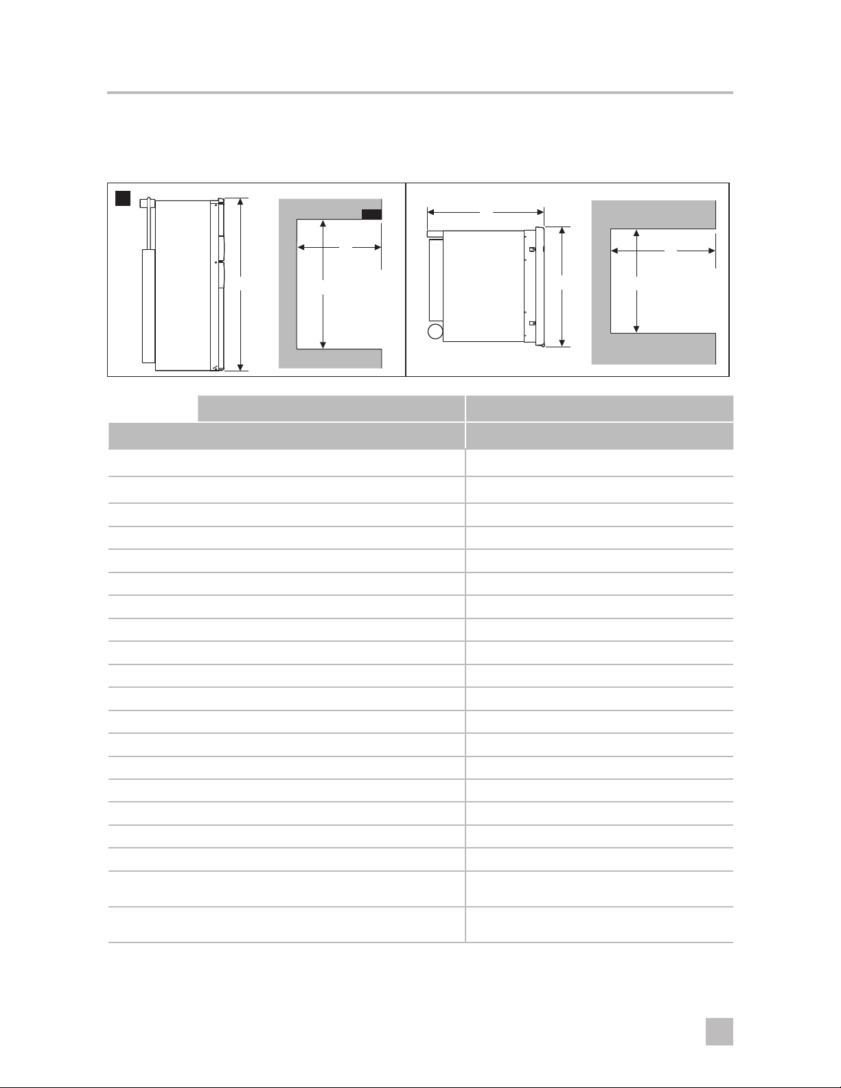
4.1 Overall and rough in dimensions for enclosure
1
C
D
A
H
B
D
W
OVERALL DIMENSIONS ENCLOSURE DIMENSIONS
MODEL Height (A) Width (B) Depth (C) Height (H) Width (W) Depth (D)
RM2351 30-3/16" 21-7/8" 22-11/16" 29-3/4" 20-1/2" 21-1/2"
RM2354 30-3/16" 21-7/8" 22-11/16" 29-3/4" 20-1/2" 21-1/2"
RM2451 37-3/8" 24-7/8" 24-11/16" 36-1/2" 23-11/16" 24"
RM2454 37-3/8" 24-7/8" 24-11/16" 36-1/2" 23-11/16" 24"
RM2551 43-1/2" 24-7/8" 24-11/16" 42-5/8" 23-11/16" 24"
RM2554 43-1/2" 24-7/8" 24-11/16" 42-5/8" 23-11/16" 24"
DM2652 54-11/16" 24-7/8" 26-1/16" 53-3/4" 23-11/16" 24"
DM2662 54-11/16" 24-7/8" 26-1/16" 53-3/4" 23-11/16" 24"
DM2663 54-11/16" 24-7/8" 26-1/16" 53-3/4" 23-11/16" 24"
DM2672 55" 24-7/8" 26-3/16" 53-3/4" 23-11/16" 24"
DM2682 55" 24-7/8" 26-3/16" 53-3/4" 23-11/16" 24"
DM2683 55" 24-7/8" 26-3/16" 53-3/4" 23-11/16" 24"
RM3762 54-3/4" 25-5/64" 26-1/16" 53-3/4" 23-11/16" 24"
DM2852 60-13/16" 24-7/8" 26-1/16" 59-15/16" 23-11/16" 24"
DM2862 60-13/16" 24-7/8" 26-1/16" 59-15/16" 23-11/16" 24"
DM2872 61-1/8" 24-7/8" 26-3/16" 59-15/16" 23-11/16" 24"
DM2882 61-1/8" 24-7/8" 26-3/16" 59-15/16" 23-11/16" 24"
RM3962 63-15/16" 25-5/64" 26-1/16" 62-15/16" 23-11/16" 24"
RM1350 64-5/16" 33-11/16" 28-1/16"1
29-1/2"
RM1350SL 64-5/16" 33-11/16" 26-1/16"1
27-1/2"
1
Steel Doors
2
Door Insert Panels
3
Add 1" depth for units with one or two optional ventilator fans.
2
2
63-3/16" 32-3/4" 26-1/16"
63-3/16" 32-3/4" 24-1/16"
3
3
3
3
3
3
3
3
3
3
3
3
5
EN
Page 6
Refrigerator
4.2 Door panel dimensions
RM2351, RM2354, RM2451, RM2454, DM2652, DM2662, DM2663, DM2672, DM2682,
DM2683, RM2551, RM2554, RM3762, DM2852, DM2862, DM2872, DM2882, RM3962
PANEL DIMENSIONS (MAX. THICKNESS 5/32")
Model Height Max. Height Min. Width Max. Width Min.
UPPER DOOR
DM2652
DM2662
DM2663
DM2852
DM2862
DM2672
DM2682
DM2683
DM2872
DM2882
RM3762
RM3962
15-27/32" 15-25/32" 20-3/4" 20-5/8"
17-25/32" 17-23/32" 22-1/4" 22-1/8"
17-3/64" 16-31/32" 23-25/32" 23-11/16"
LOWER DOOR/SINGLE DOOR
RM2351
RM2354
RM2451
RM2454
DM2652
DM2662
DM2663
RM2551
RM2554
DM2852
DM2862
DM2672
DM2682
DM2683
DM2872
DM2882
RM3762 32-7/16" 32-23/64" 23-25/32" 23-11/16"
RM3962 41-39/64" 41-9/16" 23-25/32" 23-11/16"
26-17/64" 26-3/16" 19-5/8" 19-17/32"
32-9/16" 32-1/2" 20-3/4" 20-5/8"
38-11/16" 38-5/8" 20-3/4" 20-5/8"
32-29/32" 32-27/32" 22-1/4" 22-1/8"
39-1/16" 39" 22-1/4" 22-1/8"
EN
6
Page 7

Refrigerator
RM1350
PANEL DIMENSIONS (MAX. THICKNESS 5/32")
Model Height Max. Height Min. Width Max. Width Min.
UPPER DOOR
RM1350M
RM1350SLM
RM1350MIM
19-7/32" 19-9/64" 15-43/64" 15-19/32"
RM1350WIM
RM1350WID (le)
RM1350WID (right) 9-9/32" 9-13/64" 15-43/64" 15-19/32"
LOWER DOOR
RM1350M
RM1350SLM
RM1350MIM
40-1/32" 39-31/32" 15-43/64" 15-19/32"
RM1350WIM (right)
RM1350WID
RM1350WIM (le)
A: 5-63/64"
C: 11-55/64"
E: 15-43/64"
A: 5-29/32"
C: 11-49/64"
E: 15-9/32"
B: 9-49/64"
D: 28-17/64"
F: 40-1/32"
B: 9-11/16"
D: 28-3/16"
F: 39-31/32"
+.197 +5
59.842
.295 (7.5)
(1520)
.394 - .098 (10-2.5)
11.181
(284)
45°
15.237
(387)
27.224 (691.5)
(31.279 (794.5))
2
C
D
A
B
F
E
3
0.197(2x)
Max. 1.00
(Max. 25)
in. (mm)
(5)(2x)
7
EN
Page 8

Refrigerator
4
.197(2x)
(5)(2x)
Max. 1.00
(Max. 25)
in. (mm)
6
.197(2x)
(5)(2x)
(32.106 (815.5))
28.051 (712.5)
+.197 +5
.394 - .098 (10-2.5)
16.811
(427)
45°
12.756
(324)
.295 (7.5)
+.197 +5
.394 - .098 (10-2.5)
59.842
(1520)
5
Max. 1.00
(Max. 25)
.197(2x)
(5)(2x)
Max. 1.00
(Max. 25)
in. (mm)
.197(2x)
(5)(2x)
.295 (7.5)
+.197 +5
.394 - .098 (10-2.5)
29.921
(23.2)
(760)
.913
11.181
(284)
9.370
(238)
15.237
(387)
14.960
(380)
+.197 +5
.394 - .098 (10-2.5)
.295 (7.5)
45°
27.224
(691.5)
in. (mm)
Max. 1.00
(Max. 25)
(32.106 (815.5))
28.051 (712.5)
45°
16.811
(427)
12.756
(324)
.295 (7.5)
59.842
(1520)
EN
8
Page 9
Refrigerator
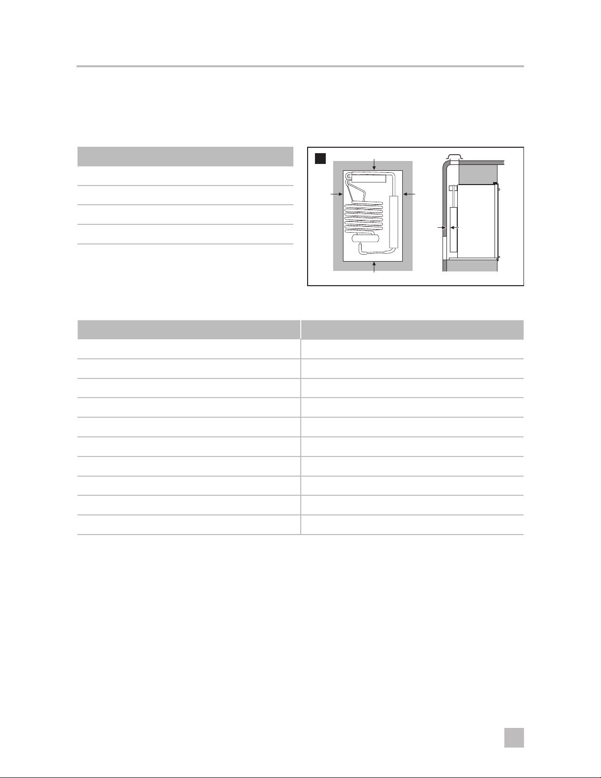
4.3 Clearances
The maximum clearances specified are necessary for correct refrigerator performance. CSA International
I
certification allows the refrigerator to have zero inch minimum clearance at the sides, rear, top, and
bottom.
Clearances
7
G
Top (G) 0" Min. to 1/4" Max.
Side (K) 0" Min. to 1/4" Max.
K
K
Bottom (L) 0" Min. to 0" Max.
M
Rear (M1) 0" Min. to 1" Max.
1
The distance between the refrigerator cooling unit and the wall or
baffle behind it
L
4.4 Minimum ventilation heights
Model B1 B2 Model B1 B2
RM2351 31" 28" DM2682 57-3/4" 56"
RM2354 31" 28" DM2683 57-3/4" 56"
RM2451 37-3/4" 36" RM3762 57-3/4" 56"
RM2454 37-3/4" 36" DM2852 63-3/4" 61"
RM2551 44-1/2" 42" DM2862 63-3/4" 61"
RM2554 44-1/2" 42" DM2872 63-3/4" 61"
DM2652 57-3/4" 56" DM2882 63-3/4" 61"
DM2662 57-3/4" 56" RM3962 66-13/16" 63"
DM2663 57-3/4" 56" RM1350 69-1/8" 63"
DM2672 57-3/4" 56" RM1350SL 69-1/8" 63"
B1 = Roof vent and lower side vent / B2 = Upper and lower side vent
➤ Measure the ventilation height from the seam between the frame and the door of the lower side wall vent,
to the top of the roof opening (B1), or to the top of the uppermost row of louvers on the upper side wall vent
(B2).
9
EN
Page 10
Refrigerator
8
Roof Vent and
Lower Side Vent
Minimum
Ventilation
Height
Upper and
Lower Side Vent
Minimum
Ventilation
Height
4.5 Approved vents
Roof Vent Application
Model Roof Vent Lower Side Vent Fan
RM2351 3311236.xxx^ 3109350.xxx^, 3316941.xxx^ 3108705.751
RM2354 3311236.xxx^ 3109350.xxx^, 3316941.xxx^ 3108705.751
RM2451 3311236.xxx^ 3109350.xxx^, 3316941.xxx^ 3108705.751
RM2454 3311236.xxx^ 3109350.xxx^, 3316941.xxx^ 3108705.751
RM2551 3311236.xxx^ 3109350.xxx^, 3316941.xxx^ 3108705.751
RM2554 3311236.xxx^ 3109350.xxx^, 3316941.xxx^ 3108705.751
DM2672 3311236.xxx^ 3109350.xxx^, 3316941.xxx^ 3108705.744
DM2682 3311236.xxx^ 3109350.xxx^, 3316941.xxx^ 3108705.744
DM2683 3311236.xxx^ 3109350.xxx^, 3316941.xxx^ 3108705.744
RM3762 3311236.xxx^ 3109350.xxx^, 3316941.xxx^ 3108705.744
DM2872 3311236.xxx^ 3109350.xxx^, 3316941.xxx^ 3108705.744
DM2882 3311236.xxx^ 3109350.xxx^, 3316941.xxx^ 3108705.744
RM3962 3311236.xxx^ 3109350.xxx^, 3316941.xxx^ 3108705.744
RM1350 3311236.xxx^ 3109349.xxx^, 3317027.xxx^
RM1350SL 3311236.xxx^
3109349.xxx^, 3109350.xxx^, 3316941.xxx^,
3317027.xxx^
•
•
*Fan(s)
*Position may
vary by model
†
†
†
†
†
†
†
†
†
†
†
†
†
* Optional vents may be used in applications where the preferred vent cannot be used
†
Optional fan. Note that some models can be purchased with factory installed fan(s)
• Fan(s) are factory installed on these models
^ Suffix "xxx" should be replaced by a color code. See "Vent Color Codes" on page 14.
EN
10
Page 11
Refrigerator
Upper & Lower Side Vent Application
Model
RM2351
RM2354
RM2451
RM2454
RM2551
RM2554
Upper
Side Vent
3109492.xxx^, 3100451.xxx^*,
80301223XX^*, 3317024.xxx^
3109492.xxx^, 3100451.xxx^*,
80301223XX^*, 3317024.xxx^
3109350.xxx^, 3109492.xxx^*,
80301223XX^*, 3316941.xxx^,
3317024.xxx^
3109350.xxx^, 3109492.xxx^*,
80301223XX^*, 3316941.xxx^,
3317024.xxx^
3109350.xxx^, 3109492.xxx^*,
80301223XX^*, 3316941.xxx^,
3317024.xxx^
3109350.xxx^, 3109492.xxx^*,
80301223XX^*, 3316941.xxx^,
3317024.xxx^
3102364.xxx/80302113XX^*,
3102364.xxx/80302113XX^*,
3109350.xxx^, 3109492.xxx^*,
3102364.xxx/80302113XX^*,
3316941.xxx^, 3317024.xxx^
3109350.xxx^, 3109492.xxx^*,
3102364.xxx/80302113XX^*,
3316941.xxx^, 3317024.xxx^
3109350.xxx^, 3109492.xxx^*,
3102364.xxx/80302113XX^*,
3316941.xxx^, 3317024.xxx^
3109350.xxx^, 3109492.xxx^*,
3102364.xxx/80302113XX^*,
3316941.xxx^, 3317024.xxx^
Lower
Side Vent
3109492.xxx^,
3317024.xxx^
3109492.xxx^,
3317024.xxx^
Fan
3108705.751
3108705.751
3108705.751
3108705.751
3108705.751
3108705.751
DM2652 3109350.xxx^, 3316941.xxx^ 3109350.xxx^, 3316941.xxx^ 3108705.744
DM2662 3109350.xxx^, 3316941.xxx^ 3109350.xxx^, 3316941.xxx^ 3108705.744
DM2663 3109350.xxx^, 3316941.xxx^ 3109350.xxx^, 3316941.xxx^ 3108705.744
DM2672 3109350.xxx^, 3316941.xxx^ 3109350.xxx^, 3316941.xxx^ 3108705.744
DM2682 3109350.xxx^, 3316941.xxx^ 3109350.xxx^, 3316941.xxx^ 3108705.744
DM2683 3109350.xxx^, 3316941.xxx^ 3109350.xxx^, 3316941.xxx^ 3108705.744
RM3762 3109350.xxx^, 3316941.xxx^ 3109350.xxx^, 3316941.xxx^ 3108705.744
DM2852 3109350.xxx^, 3316941.xxx^ 3109350.xxx^, 3316941.xxx^ 3108705.744
DM2862 3109350.xxx^, 3316941.xxx^ 3109350.xxx^, 3316941.xxx^ 3108705.744
DM2872 3109350.xxx^, 3316941.xxx^ 3109350.xxx^, 3316941.xxx^ 3108705.744
DM2882 3109350.xxx^, 3316941.xxx^ 3109350.xxx^, 3316941.xxx^ 3108705.744
RM3962 3109350.xxx^, 3316941.xxx^ 3109350.xxx^, 3316941.xxx^ 3108705.744
†
†
†
†
†
†
†
†
†
†
†
†
†
†
†
†
†
†
RM1350 3109349.xxx^, 3317027.xxx^ 3109349.xxx^, 3317027.xxx^ •
RM1350SL
3109349.xxx^, 3109350.xxx^,
3316941.xxx^, 3317027.xxx^
3109349.xxx^, 3109350.xxx^,
3316941.xxx^, 3317027.xxx^
* Optional vents may be used in applications where the preferred vent cannot be used
†
Optional fan. Note that some models can be purchased with factory installed fan(s)
• Fan(s) are factory installed on these models
^ Suffix "xxx" should be replaced by a color code. See "Vent Color Codes" on page 14.
11
•
EN
Page 12
Refrigerator
Corner Application
Model Roof Vent
RM2351 3311236.xxx^
RM2354 3311236.xxx^
RM2451 3311236.xxx^
RM2454 3311236.xxx^
RM2551 3311236.xxx^
RM2554 3311236.xxx^
Upper
Side Vent
3109492.xxx^, 80301223xx^†,
3317024.xxx^
3109492.xxx^, 80301223xx^†,
3317024.xxx^
3109350.xxx^, 3109492.xxx^*,
80301223xx^*, 3316941.xxx^,
3317024.xxx^
3109350.xxx^, 3109492.xxx^*,
80301223xx^*, 3316941.xxx^,
3317024.xxx^
3109350.xxx^, 3109492.xxx^*,
80301223xx^*, 3316941.xxx^,
3317024.xxx^
3109350.xxx^, 3109492.xxx^*,
80301223xx^*, 3316941.xxx^,
3317024.xxx^
3102364.xxx/80302113xx^†,
3102364.xxx/80302113xx^†,
3109350.xxx^, 3109492.xxx^*,
3102364.xxx/80302113xx^*,
3316941.xxx^, 3317024.xxx^
3109350.xxx^, 3109492.xxx^*,
3102364.xxx/80302113xx^*,
3316941.xxx^, 3317024.xxx^
3109350.xxx^, 3109492.xxx^*,
3102364.xxx/80302113xx^*,
3316941.xxx^, 3317024.xxx^
3109350.xxx^, 3109492.xxx^*,
3102364.xxx/80302113xx^*,
3316941.xxx^, 3317024.xxx^
Lower
Side Vent
3109492.xxx^,
3317024.xxx^
3109492.xxx^,
3317024.xxx^
Fan
3108705.751
3108705.751
3108705.751
3108705.751
3108705.751
3108705.751
DM2652 3311236.xxx^ 3109350.xxx^, 3316941.xxx^ 3109350.xxx^, 3316941.xxx^ 3108705.744
DM2662 3311236.xxx^ 3109350.xxx^, 3316941.xxx^ 3109350.xxx^, 3316941.xxx^ 3108705.744
DM2663 3311236.xxx^ 3109350.xxx^, 3316941.xxx^ 3109350.xxx^, 3316941.xxx^ 3108705.744
DM2672 3311236.xxx^ 3109350.xxx^, 3316941.xxx^ 3109350.xxx^, 3316941.xxx^ 3108705.744
DM2682 3311236.xxx^ 3109350.xxx^, 3316941.xxx^ 3109350.xxx^, 3316941.xxx^ 3108705.744
DM2683 3311236.xxx^ 3109350.xxx^, 3316941.xxx^ 3109350.xxx^, 3316941.xxx^ 3108705.744
RM3762 3311236.xxx^ 3109350.xxx^, 3316941.xxx^ 3109350.xxx^, 3316941.xxx^ 3108705.744
DM2852 3311236.xxx^ 3109350.xxx^, 3316941.xxx^ 3109350.xxx^, 3316941.xxx^ 3108705.744
DM2862 3311236.xxx^ 3109350.xxx^, 3316941.xxx^ 3109350.xxx^, 3316941.xxx^ 3108705.744
DM2872 3311236.xxx^ 3109350.xxx^, 3316941.xxx^ 3109350.xxx^, 3316941.xxx^ 3108705.744
DM2882 3311236.xxx^ 3109350.xxx^, 3316941.xxx^ 3109350.xxx^, 3316941.xxx^ 3108705.744
RM3962 3311236.xxx^ 3109350.xxx^, 3316941.xxx^ 3109350.xxx^, 3316941.xxx^ 3108705.744
†
†
†
†
†
†
†
†
†
†
†
†
RM1350 3311236.xxx^ 3109349.xxx^, 3317027.xxx^ 3109349.xxx^, 3317027.xxx^ •
RM1350SL 3311236.xxx^
3109349.xxx^, 3109350.xxx^,
3316941.xxx^, 3317027.xxx^
3109349.xxx^, 3109350.xxx^,
3316941.xxx^, 3317027.xxx^
* Optional vents may be used in applications where the preferred vent cannot be used
†
Optional fan. Note that some models can be purchased with factory installed fan(s)
• Fan(s) are factory installed on these models
^ Suffix "xxx" should be replaced by a color code. See "Vent Color Codes" on page 14.
EN
•
12
Page 13
Refrigerator
Island Application
Model Roof Vent Fan
RM2351 3311236.xxx^ 3108705.751
RM2354 3311236.xxx^ 3108705.751
RM2451 3311236.xxx^ 3108705.751
RM2454 3311236.xxx^ 3108705.751
RM2551 3311236.xxx^ 3108705.751
RM2554 3311236.xxx^ 3108705.751
DM2652 3311236.xxx^ 3108705.744
DM2662 3311236.xxx^ 3108705.744
DM2663 3311236.xxx^ 3108705.744
DM2672 3311236.xxx^ 3108705.744
DM2682 3311236.xxx^ 3108705.744
DM2683 3311236.xxx^ 3108705.744
RM3762 3311236.xxx^ 3108705.744
DM2852 3311236.xxx^ 3108705.744
DM2862 3311236.xxx^ 3108705.744
DM2872 3311236.xxx^ 3108705.744
DM2882 3311236.xxx^ 3108705.744
RM3962 3311236.xxx^ 3108705.744
†
†
†
†
†
†
†
†
†
†
†
†
RM1350 3311236.xxx^ •
RM1350SL 3311236.xxx^ •
* Optional vents may be used in applications where the preferred vent cannot be used
†
Optional fan. Note that some models can be purchased with factory installed fan(s)
• Fan(s) are factory installed on these models
^ Suffix "xxx" should be replaced by a color code. See "Vent Color Codes" on page 14.
13
EN
Page 14
Refrigerator
Vent Color Codes
Side Vents Black White Tan Ivory
3109350.XXX 3109350.065 3109350.011 3109350.102 3109350.110
3109429.XXX 3109492.004 3109492.003 N/A N/A
3109349.XXX 3109349.065 3109349.005 N/A N/A
3316941.XXX 3316941.000 3316941.010 3316941.020 3316941.030
3317024.XXX 3317024.000 3317024.010 3317024.020 3317024.030
3317027.XXX 3317027.000 3317027.010 3317027.020 3317027.030
3102364.XXX N/A 3102364.019 N/A N/A
80302113XX N/A 8030211322 N/A N/A
80301223XX N/A 8030122320 N/A N/A
3100451.XXX N/A 3100451.024 N/A N/A
Roof Vents Black White
3311236.XXX 3311236.024 3311236.000
Other colors may be available for replacement upon request.
I
EN
14
Page 15

Refrigerator
5 PREPARE FOR INSTALLATION
FIRE OR EXPLOSION HAZARD. Failure to obey the following warnings could result in serious
injury or death:
• Turn off LP gas supply at the tank.
• Never use an open flame to check for gas leaks.
5.1 Removing the existing refrigerator
Proceed to "5.2 Preparing the refrigerator
I
enclosure" if a refrigerator is not already
present.
9
➤ Unplug the 120 VAC power cord from the
receptacle at the rear of the refrigerator enclosure.
➤ Disconnect the 12 VDC leads from the refrigerator
and cap the lead ends.
➤ Turn off the LP gas supply to the refrigerator.
➤ Disconnect the LP gas line from the refrigerator.
Cap the line and verify there are no LP gas leaks
➤ Remove the screws anchoring the refrigerator to
the enclosure.
➤ Slide the refrigerator out of the enclosure and
remove it from the RV.
5.2 Preparing the refrigerator
enclosure
Inspecting the refrigerator enclosure
➤ Verify the following to inspect the refrigerator
enclosure:
• There are no holes, other than ventilation holes,
inside the enclosure.
• The surface for sealing strips is clean and flat to
allow a complete seal.
• No objects are protruding into the enclosure,
except utility connections for the refrigerator.
• The enclosure seams are sealed to prevent flue
gases from leaking into the living area.
• Utility hookups are present and comply with all
applicable codes.
Assembling the refrigerator enclosure
➤ Ensure the following when assembling the
refrigerator enclosure:
• The refrigerator must be level and installed in a
sturdy enclosure.
• The floor must be level and able to support the
weight of the refrigerator and its contents.
• Adjacent heat sources must not affect the
ventilation of the refrigerator.
• All joints in the enclosure must be sealed to
prevent flue gases from leaking into the living area.
• The enclosure must be free of materials that may
damage the refrigerator.
• A wood strip must be placed above the upper
opening of the enclosure. The top frame of the
refrigerator is anchored to the wood strip with
screws.
• The refrigerator must not be installed directly on
carpeting.
15
EN
Page 16

Refrigerator
5.3 Choosing the type of vent application
Read before proceeding:
I
• Certified installation requires one lower fresh air intake vent and one upper exhaust vent.
• Center the vents to the back of the refrigerator. Refer to "Offset vent application" if it is not possible to center
the vent.
• Use only the Dometic vents specified for the installation.
• Ensure that vent openings are clear of obstructions.
• Ensure that the lower vent opening is even with, or below, floor level to allow any raw LP gas to escape.
• Do not allow the floor to block or interfere with the vent openings.
• Additional holes are required for vents installed above floor level to vent raw LP gas outdoors. The holes must
be a diameter of 1-3/4", clear of any obstruction, and covered with a screen (minimum 14 X 14 per inch).
Roof vent application
• This application is recommended for typical installations.
• This application can be used if the vents are inboard or offset due to a radius roof or interference with
building materials.
➤ Check the enclosure depth and add a baffle, if required.
Upper and lower side vent application
• Choose this type of installation when a roof vent installation is not possible.
• A baffle should be added.
• The refrigerator must be equipped with fan(s).
Island application
• This application is intended for refrigerators installed on an inside wall and must be vented through the floor
to the ceiling.
Corner application
• This application is intended for refrigerators installed in the rear corner of the vehicle or in an angled cabinet.
• The refrigerator must be equipped with fan(s).
Offset vent application
• The vents must always be offset toward the flue side of the cooling unit.
• For offset vent applications, prior written approval and safety certification must be obtained from Dometic
Corporation.
EN
16
Page 17

Refrigerator
5.4 Installing the vent application
FIRE OR EXPLOSION HAZARD. Make sure vent allows raw (unburned) LP Gas to escape to the
outside. LP Gas is heavier than air, and will collect at floor level if not vented correctly. Failure to obey this warning
could result in death or serious injury.
Read before proceeding:
I
• Use the inboard installation option when the radius of the roof, or the presence of building materials,
interferes with the placement of the roof vent.
• All fasteners are to be provided by the installer.
• Select the appropriate screw types for the application for which they are being used.
• Minimize screw lengths to fit applications appropriately, unless otherwise noted.
• Rivets are acceptable only where noted.
➤ Apply sealant around the thread or rivet body of all fasteners.
➤ Apply dry sealant around the surface mounting face of all vent frames or vent bases before installation.
➤ Apply wet sealant around the perimeter of all vent frames or vent bases aer installation. Do not allow the
sealant to block the molded weep tracks in the vent frame.
Roof vent application
10
Side
View
Roof Vent
Box Baffle
Recess Depth
11
Side
View
Roof Vent
Box Baffle
Recess Depth
17
EN
Page 18

Refrigerator
Plastic roof vent (No. 3311236.xxx)
12
Cutout
23-3/4"
6-1/2"
➤ Confirm ventilation height. Refer to "4.4 Minimum ventilation heights" on page 9.
➤ Confirm the recess depth. Refer to "5.5 Recess depth" on page 22.
➤ Install a box baffle, if required.
➤ Install the lower side vent. Refer to "Side vents" on page 19.
➤ Center the roof vent base over the cutout.
➤ Secure the roof vent base using sixteen #10 screws (not provided).
➤ Place the cap on top of the base.
➤ Secure the cap to base using four #10 screws (not provided). The screws must be a minimum of 1-1/4".
➤ Apply sealant over all the screws.
Upper and lower side application
➤ Confirm ventilation height. Refer to "4.4 Minimum ventilation heights" on page 9.
➤ Confirm the recess depth. Refer to "5.5 Recess depth" on page 22.
➤ Install a box baffle above the lower access vent, if required.
➤ Install the lower side vent.
➤ Install the upper side vent.
Refer to "Side vents" on page 19 for specific instructions on installing the side vents.
I
EN
18
Page 19

Refrigerator
Side vents
Upper and Lower Plastic Side Vent
(No. 3109350.xxx)
Upper Metal Side Vent (No. 3100451.xxx)
13
13-3/4"
➤ Place the frame into the cutout.
➤ Secure the frame using seven #10 screws (not
provided) through the inside flange of the frame.
Seven Z-brackets could be used if the wall is
I
of laminate construction. Use #10 screws (not
provided) to secure the frame with Z-brackets.
➤ Install the vent door into the frame using the upper
tabs as a guide.
➤ Lock the vent door into place by fully seating and
twisting the black latches in the bottom corners of
the vent door.
21-9/16"
Cutout
14
19-1/4"
Cutout
7-3/4"
➤ Place the vent over the cutout.
➤ Secure the frame using fourteen #10 screws Not
provided).
Rivets could be used for this vent.
I
Upper Metal Side Vent (No. 80301223xx)
15
21"
10-1/4"
➤ Place the vent over the cutout.
➤ Secure the frame using sixteen #10 screws (not
provided).
Rivets could be used for this vent.
I
Cutout
Lower Metal Side Vent (No. 3102364.xxx,
80302113xx)
16
19-1/4"
Cutout
9-11/16"
➤ Place the vent over the cutout.
➤ Secure the frame using sixteen #10 screws (not
provided).
Rivets could be used for this vent.
I
19
EN
Page 20

Refrigerator
Upper and Lower Plastic Side-By-Side Vent
(No. 3109349.xxx)
17
28-5/8"
Cutout
13-5/8"
➤ Place the frame into the cutout.
➤ Secure the frame with five Z-brackets.
➤ Install six #10 screws (three on each end, not
provided) to completely secure the frame.
➤ Remove the screw cap plugs from the vent frame
and install them over the six screws in the front
frame.
➤ Install the vent door into the frame using the upper
tabs as a guide.
➤ Lock the vent door into place by fully seating and
twisting the black latches in the bottom corners of
the vent door.
Upper and Lower Plastic Side Vent
(No. 3109492.xxx)
18
19-1/4"
Cutout
9-11/16"
➤ Place the frame into the cutout.
➤ Secure the frame with seven Z-brackets using #10
screws (not provided).
➤ Install the vent door into the frame using the upper
tabs as a guide.
➤ Lock the vent door into place by fully seating and
twisting the black latches in the bottom corners of
the vent door.
Upper and Lower Plastic Side Vent
(No. 3316941.xxx)
19
21-9/16"
Cutout
13-3/4"
➤ Place the frame into the cutout.
➤ Secure the frame using sixteen #8 screws (not
provided) through the inside flange of the frame.
➤ Install the vent door into the frame using the lower
tabs as a guide.
➤ Lock the vent door into place by fully seating and
twisting the latches in the top corners of the vent
door.
Upper and Lower Plastic Side Vent
(No. 3317027.xxx)
20
28-5/8"
Cutout
13-3/4"
➤ Place the frame into the cutout.
➤ Secure the frame using sixteen #8 screws (not
provided) through the inside flange of the frame.
➤ Install the vent door into the frame using the lower
tabs as a guide.
➤ Lock the vent door into place by fully seating and
twisting the latches in the top corners of the vent
door.
EN
20
Page 21

Refrigerator
Upper and Lower Plastic Side Vent
(No. 3317024.xxx)
21
19-1/4"
Cutout
9-11/16"
➤ Place the frame into the cutout.
➤ Secure the frame using twelve #8 screws (not
provided) through the inside flange of the frame.
➤ Install the vent door into the frame using the lower
tabs as a guide.
➤ Lock the vent door into place by fully seating and
twisting the latches in the top corners of the vent
door.
Fan (Innovator Refrigerator Ventilation
System*) (No. 3108705.751, 3108705.744)
22
*Patent #5,355,693
Z-Bracket (No. 3103812.xxx)
23
Side
View
Wall or Frame
Vent Frame Vent Frame
Wall or Frame
D
Z-Bracket
D
Z-Bracket
Use appropriate D:
xxx = 016 = .62"
xxx = 024 = .81"
xxx = 040 = .19"
21
EN
Page 22

Refrigerator
5.5 Recess depth
Side
24
View
Max. 1"
(without baffle)
Island application
26
25
27
Side
View
1/2"
Below
Fins
Box Baffle
Box Baffle
Access Panel
Minimum
Ventilation
Height
Access
Panel
Duct
and Fan
Access
Panel
Duct
and Fan
Box Baffle
Recess Depth
➤ Confirm the ventilation height. Refer to "4.4
Minimum ventilation heights" on page 9.
➤ Confirm the recess depth. Refer to"5.5 Recess
depth" above.
➤ Install a box baffle above the lower access panel, if
required.
14"
22"
➤ Install the access panel.
28
Fan
(Centered
Horizontally)
1/4" x 0.025"
Metal Mesh
L
Min. 3"
Max. 8"
➤ Install the air duct.
➤ Install the roof vent. Refer to "Roof vent
application" on page 17.
D
W
EN
22
Page 23

Refrigerator
Corner application with roof vent
29
Side
View
Minimum
Ventilation
Vent Cutout
Height
➤ Confirm the ventilation height. Refer to "4.4
Minimum ventilation heights" on page 9.
Corner application with upper and lower side vents
31
30
Top
View
Baffle
Vent Cutout
Recess
Depth
Roof Vent
➤ Confirm the recess depth. Refer to "5.5 Recess
depth" on page 22.
➤ Install the lower side vent. Refer to "Side vents" on
page 19.
➤ Install the roof vent. Refer to "Roof vent
application" on page 17.
32
Baffle
Upper
Side Vent
Minimum
Ventilation
Height
*Fan
*Position may
vary by model
➤ Confirm the ventilation height. Refer to "4.4
Minimum ventilation heights" on page 9.
Baffle
Recess
Depth
Lower
Side Vent
➤ Confirm the recess depth. Refer to "5.5 Recess
depth" on page 22.
➤ Install the lower side vent. Refer to "Side vents" on
page 19.
➤ Install the upper side vent. Refer to "Side vents" on
page 19.
23
EN
Page 24

Refrigerator
Offset vent - upper and lower side vent
33
Center of
Refrigerator
Prior written approval and safety certification must be obtained from Dometic Corporation for this
I
application.
➤ Confirm the ventilation height. Refer to "4.4 Minimum ventilation heights" on page 9.
➤ Confirm the recess depth. Refer to "5.5 Recess depth" on page 22.
➤ Install the lower side vent. Refer to "Side vents" on page 19.
➤ Install the upper side vent or roof vent. Refer to "Side vents" on page 19, or "Roof vent application" on
page 17.
Offset vent - side and roof vent
34
Center of
Refrigerator
5.6 Placing the insulation
Read before proceeding:
I
• Dimensions will vary by model.
• If there is more than 1/4" between the side or top of the refrigerator and the inside of the enclosure, fill the
space with insulation, baffles, or other non-flammable fabricated seals.
• Do not allow insulation to come into contact with the cooling unit.
➤ Cut the insulation two to three inches shorter than the depth of the enclosure.
➤ Secure the insulation to the enclosure walls and ceiling. This will prevent it from shiing when the refrigerator
is installed.
35
Insulation
Refrigerator
Rear Side To p
2" – 3"
Insulation
Refrigerator
2" – 3"
Insulation
EN
24
Page 25

Refrigerator
5.7 Connecting the water supply
For refrigerator models equipped with ice maker, ice and water dispensers:
➤ Ensure that the water supply system has a minimum pressure of 15 pounds per square-inch (psig).
➤ Use a 1/4" diameter water line to the water valve at the rear of the refrigerator.
➤ Ensure that the water line is equipped with a manual shut-off valve that is easily accessible.
6 INSTALLATION
6.1 Installing the refrigerator
Refrigerator model RM1350SL is equipped with vacuum-insulated panel technology. The insulating
I
panels are located on the top, back, sides, and doors. If the surface is punctured, the effectiveness of the
insulation will be reduced, resulting in poor refrigerator performance.
36
Do NOT remove factory
installed sealing strip
*RM2351, RM2354
Apply sealing strip to floor
➤ Carefully place the refrigerator in the enclosure.
➤ Verify that there is a complete seal between the front frame of the refrigerator and the top, sides and bottom
of the enclosure.
A length of sealing strip is applied to the rear surface of the front frame of the refrigerator. The sealing strip
I
provides complete isolation of the combustion system from the vehicle interior.
➤ RM2351, RM2354: Apply a sealing strip to the front edge of the enclosure floor. Do not damage the
sealing strip when the refrigerator is put in place.
RM2351 & RM2354: Do not remove the factory-installed sealing strip at the top rear corner of the
I
cabinet. It is not part of the shipping materials and must be le intact.
Seal
Seal
25
EN
Page 26

Refrigerator
6.2 Securing the refrigerator
The following steps must be completed in order to prevent leakage between the refrigerator and the
I
enclosure.
RM2351, RM23514
37
Plug
Screw
Front
Frame
Seal
Do NOT
remove
factoryinstalled
sealing
strip
Rear
Base
➤ Install four screws (not provided) through the front
frame.
➤ Install one screw (not provided) in the rear base.
➤ Cover the screw heads using the plugs provided
RM2451, RM2454, RM2551, RM2554, DM2652,DM2662, DM2663, DM2852, DM2862
38
Rear
Base
Screw
Front
Base
Lower
Front
Strip
39
Hinge
Top Panel
➤ Install the lower front strip by sliding it under the
bottom hinge plate. Refer to "6.3 Installing the
hinge plate" on page 29.
➤ Secure the refrigerator and the lower front strip
using two screws (not provided).
EN
➤ Gently remove the tabs from the hole in the
hinge plate, on both sides, using a flat-bladed
screwdriver.
➤ Tilt the top decoration panel and li to remove it
from the top frame. Do not damage the circuit
board and wires.
➤ Install two screws (not provided) in the top frame.
➤ Seal the opening for the screws with aluminum
tape (not provided).
➤ Replace the top decoration panel. Do not pinch
the wires behind the panel.
26
Page 27

Refrigerator
40
Optional Screw
➤ Install one screw (not provided) in the rear base.
An optional screw may be added on the opposite
side.
DM2672, DM2682, DM2683, DM2872 & DM2882
41
Bottom Frame
➤ Secure the refrigerator using two screws (not
provided) through the bottom frame of the
refrigerator.
43
Screw
Top Frame
Screw
42
Adhesive Backing
Lower Front Strip
➤ Remove the three pieces of adhesive backing tape
from the lower front strip.
➤ Align the lower front strip to the bottom frame and
install it by firmly pressing the trim piece to the
frame.
44
Top Panel
➤ Install two screws (not provided) through the holes
underneath the top frame.
➤ Seal the opening for the screws using the black
labels provided.
27
Adhesive Backing
➤ Remove the three pieces of adhesive backing tape
from the top decoration panel.
➤ Align the top decoration panel to the top frame
and install by firmly pressing the trim piece onto
the frame.
EN
Page 28

Refrigerator
45
Optional Screw
➤ Install one screw (not provided) in the rear base.
An optional screw may be added on the opposite
side.
RM3762, RM3962
46
Screw
Top Decoration
Panel
➤ Secure the refrigerator using two screws (not
provided) through the holes underneath the top
decoration panel.
➤ Seal the openings for the screws on the metal
frame using tape or sealant.
➤ Install the lower front strip by sliding it under the
bottom hinge plate. Refer to "6.3 Installing the
hinge plate" on page 29.
➤ Secure the refrigerator and the lower front strip
using two screws (not provided).
47
Optional Screw
➤ Install one screw in the rear base. An optional
screw may be added on the opposite side.
EN
28
Page 29

Refrigerator
RM1350, RM1350SL
48
Screw
Top Panel
➤ Secure the refrigerator using two screws (not
provided) through the holes underneath the top
decoration panel.
➤ Seal the openings for the screws on the metal
frame using tape or sealant.
➤ Install the lower front strip by sliding it under the
bottom hinge plate. Refer to "6.3 Installing the
hinge plate" on page 29.
➤ Secure the refrigerator and the lower front strip
using two screws (not provided).
49
Ice Maker Cord
(optional)
Screw
➤ Install one screw (not provided) in the rear base.
An optional screw may be added on the opposite
side.
6.3 Installing the hinge plate
The refrigerator is provided with a lower front strip that is shipped as a loose part.
I
➤ Attach the front strip aer the refrigerator is set into the cutout opening.
50
Screw
Hinge
Plate
Front Strip
➤ Slide the lower front strip under the bottom hinge plate(s).
➤ Secure the hinge plate(s) and the lower front strip using two screws (not provided).
51
Screw
Hinge Plate
Front Strip
29
EN
Page 30

Refrigerator
6.4 Installing the drain water hose
FIRE HAZARD. Do not allow the drain tube to contact the burner assembly or boiler casing.
Failure to obey this warning could cause a fire resulting in death or serious injury.
Read before proceeding:
I
• The perforated plug must be present at the end of the drain water hose.
• The drain water hose must not be kinked or routed uphill.
52
Hose
Option 1 - through the floor
➤ Drill a hole through the flooring.
➤ Place sealant around the hole.
➤ Confirm that the supplied hose is long enough.
➤ Supply an extra length of hose, if needed.
Option 2 - through vent frame (plastic vents only)
➤ Pull the end of the hose through the louvers in the vent door.
➤ Cut the hose to length.
➤ Reinstall the perforated plug.
Option 3 - hanging clip (plastic vents only)
➤ Install the clip (not provided, part number 3106559.xxx) during vent installation.
➤ Insert the hose into the “j” portion of clip.
➤ Cut the hose to length.
➤ Reinstall the perforated plug.
➤ Ensure that the hose is positioned to drain into the uppermost row of louvers in the vent door.
Option 4 - through vent door (side-by side plastic vent only)
➤ Drill a 5/8" hole in the vent frame directly above the floor line.
➤ Route the drain hose through the hole and cut it to length.
➤ Reinstall the perforated plug on the outside of the vent frame.
➤ Apply sealant around the plug to ensure water does not seep into the enclosure.
Option 5 – attached to vent frame (3316941.xxx, 3317027.xxx, and 3317024.xxx only)
➤ Remove the perforated plug.
➤ Cut the hose to length.
➤ Push the end of the hose through the attachment feature located on the vent frame.
EN
30
Page 31

Refrigerator
6.5 Connecting the gas
FIRE OR EXPLOSION HAZARD. Failure to obey the following warnings could result in property
damage, serious injury, or death:
• Install gas connections in compliance with the applicable supplemental directives listed in this manual. Refer
to"1.3 Supplemental directives" on page 3.
• Never use an open flame to check for gas leaks. Use a commercial leak detection solution to check all
connections, as specified in these instructions.
• Should the gas supply fail to shut off or if overheating occurs, shut off the gas valve to the refrigerator before
shutting off the electrical supply.
• Do not put sealing compound on flair fittings.
• Never use a wire or pin to clear obstructions from burner jet (damage will occur).
• Do not attempt to adjust burner jet.
Read before proceeding:
I
• Connection to the gas supply line is accomplished at the manual gas valve. The manual gas valve is furnished
with a 3/8" SAE (UNF 5/8" -18) male flare connection.
• The gas supply system must incorporate a pressure regulator to maintain a supply pressure of not more than
11" water column.
• When testing the gas supply system at test pressures:
– greater than 1/2 psi, the refrigerator and its individual shutoff valve must be disconnected from the gas
supply piping system.
– 1/2 psi, or less, the refrigerator must be isolated from the gas supply piping system by closing the
individual manual shutoff valve.
• If local codes allow for the use of a flexible gas appliance connector, do not use a connector that has
previously serviced another gas appliance.
• If detailed instructions on the installation and connection to the gas supply are required, contact the nearest
dealer or distributor.
➤ Always use two wrenches to hold the valve and flair nut when loosening and tightening gas connections.
➤ Route all connections to avoid contact with the boiler casing, burner cover, or any other refrigerator
components.
➤ Perform an air pressure test on the piping system.
➤ Examine all completed connections for leaks using a commercially available soap solution made for the
detection of leaks.
RM2351, RM2354
53
Flexible Cord
31
Relay
Power
Module
Cover
12 VDC
Terminal
Block
Inlet
Fitting
Manual Gas
Shutoff Valve
Burner Jet
1 Heater
(RM2351)
2 Heaters
(RM2354)
Flue Baffle
Drain Water
Hose
Protection
Cover
Cover Screw
EN
Page 32

Refrigerator
RM2451, RM2454, RM2551, RM2554
54
Flexible Cord
Power
Module
Cover
Relay
(3-way ONLY)
12 VDC
Terminal
Block
Inlet Fitting
Drain
Water
Hose
Cover Screw
Burner Jet
Manual Gas Shutoff Valve
Heater
Flue Baffle
Protection
Cover
DM2672, DM2682, DM2683, DM2872, DM2882, DM2652, DM2662, DM2663, DM2852,
DM2862
55
Power Module Cover
Relay
(3-way ONLY)
Drain
Water
Hose
Thermofuse
Cover
Screw
Heater(s)
Flue Baffle
Protection Cover
Flexible Cord
RM3762, RM3962
56
Power Module
Flexible Cord
12 VDC
Terminal
Block
D+
12 VDC
Terminal
Block
Drain
Water
Hose
Inlet
Fitting
Inlet
Fitting
Burner Jet
Manual Gas Shutoff Valve
Heater
Thermofuse
Flue Baffle
Cover
Screw
Protection Cover
Burner Jet
Manual Gas Shutoff Valve
EN
32
Page 33

Refrigerator
RM1350M, RM1350SLM
57
Heaters
Drain Water Hose
Protection Plate
Power
Module
LP Gas Connection
12 VDC Terminal Block
RM1350IM, RM1350MIM, RM1350WIM
58
Water Hose
Ice maker
Heaters
Protection
Plate
LP Gas Connection
Heating Cable
Drain
Water
Hose
Power Module
Thermostat
Water Valve
12 VDC Terminal Block
*Valid for refrigerators equipped with the automatic door locking system
Flexible Cord
Water Hose - Door
(RM1350WIM ONLY)
Heating Cable
(RM1350WIM ONLY)
Flexible Cord
(Ice maker)
Flexible Cord
(Refrigerator)
*Alternator Signal Wire
RM1350WID
59
33
Water Hose
Ice maker
Protection
Plate
Heaters
LP Gas Connection
Heating Cable
Control Unit
Power Module
Thermostat
Water Valve
Drain
Water
Hose
Alternator Signal Wire
12 VDC Terminal Block
Water Hose
Water Dispenser (Door)
Flexible Cord
(Ice Dispenser)
Flexible Cord
(Refrigerator)
Heating Cable
EN
Page 34

Refrigerator
6.6 Connecting the electrical
120 VAC connection
120 VAC
60
Connection
3" – 6"
The free length of the cord is 2'.
I
➤ Install the electrical receptacle on the opposite
side of the burner assembly, and 3–6" above the
refrigerator, to allow easy access through the vent
door.
12 VDC connection
Read before proceeding:
I
• RM2451, RM2551, DM2652, DM2672,
DM2872, DM2852, RM3762, RM3962,
RM1350, & RM1350SL refrigerator models are
not designed for 12 VDC operation of the cooling
system. However, 12 VDC must be supplied to
operate the controls.
• RM2354, RM2454, RM2554, DM2662,
DM2663, DM2682, DM2683, DM2862,
& DM2882 refrigerator models require a
continuous 12 VDC supply to maintain the
automatic energy system.
MAXIMUM WIRE LENGTH
Model
RM2351, RM2451, RM2551,
DM2652, DM2662,
DM2672, DM2682,
DM2852, DM2862,
DM2872, DM2882,
RM3762, RM3962, RM1350,
RM1350SL,
RM2354, RM2454,
RM2554, DM2663, DM2683
Wire
Size
(AWG)
14
12
10
8
Wire
Length
(Feet)
17
27
17
27
Alternator (D+) connection
RM3762, RM3962, RM1350 & RM1350SL
I
(with the automatic door locking system)
• The refrigerator requires a signal wire connection
from the vehicle's alternator (D+) to maintain
temporary gas lock-out function, and the
automatic travel door-latch for RM1350 and
RM1350SL.
• The gas operation will automatically lock out for
15 minutes when the engine is switched off, to
prevent gas operation when stopping at a fuel
station.
EN
61
Alternator Signal Wire
to the Refrigerator
D+–+
➤ Connect the vehicle's alternator (D+) to the D+ on
the terminal block
Ignition Switch
Charge Light
D+
B+
Alternator
Battery
34
Page 35

Refrigerator
RM2351, RM2451, RM2551
62
+12V
L
3A
J4
5A
J5 J7
J2
P3
1 1 12 2 23 3 54 4 6
E
P1 P2
T
Display
Board
N
N
J6
J8
J10
M
RM2354, RM2454, RM2554
63
+12V
L
W
3A
J4
J5
5A
J2
P3
P1 P2
1
2
3 544 6
1
2
3
X
Display
Board
E
85
87
86 30
O
Ground
N
J6
J7
J8
J10
K
1
2
N
J
P
Ground
J
A Circuit Board Power S Chassis Ground
B Fuse 3A T Test Point
C Fuse 5A 1 Black
D Circuit Board Display 2 Brown
E Electrode 3 Red
J Heater 120 VAC 4 Yellow
L Terminal Block 5 Green
M Thermistor 6 Green/Yellow
N Solenoid Valve 7 Blue
O Retainer 8 Gray
P Protective Earth 9 White
A Circuit Board Power U Chassis Ground
B Fuse 3A W Fuse 30A
C Fuse 5A X Test Point
D Circuit Board Display 1 Black
E Electrode 2 Brown
J Heater 120 VDC 3 Re d
K Heater 120 VAC 4 Yellow
M Terminal Block 5 Green
N Thermistor 6 Green/Yellow
O Solenoid Valve 7 Blue
P Relay 8 Gray
R Retainer 9 White
S Protective Earth
D
D
Orange
M
Orange
N
5
3
2
1
X
3
2
1
T
P1–1
P1–4
7
P1–2
P1–5
P1–6
P1–3
9
P2–1
P2–2
9
5
P1–1
P1–4
7
P1–2
P1–5
P1–6
P1–3
9
P2–1
9
P2–2
B
B
J2 J4 J5 J6 J7J8 J10
A
C
J2 J4 J5 J6 J7 J8 J10
3
1
9
5
LLN
A
C
3
1
9
5
M
+
LSN
12VDC
1
–
+
12VDC
P3–4
P3–3
P3–2
P3–1
1
1
3
P3–4
P3–3
4
P3–2
P3–1
8
1
1
1
1
P
–
7
K
1
1
8
U
6
N
9
E
J
S
6
7
4
9
3
J
O
P
O
3
W
E
R
DM2672, DM2682, DM2872, DM2882, DM2652, DM2662, DM2852, DM2862 (no fan) with &
without ice maker
35
64
+12V
L
J4
3A
J5
5A
J2
P3 P1 P2
1234 12123456
T
Display
Board
E
N
U
F
G
H
K
J10
Ground
N
J6
J7
J8
J
M
A Circuit Board Power P Protective Earth
B Fuse 3A S Chassis Ground
C Fuse 5A T Test Point
D Circuit Board Display U Thermal Fuse
E Electrode 1 Black
F Thermofuse 2 Brown
G Lamp 3 Red
H Switch Lamp 4 Yellow
J Heater 120 VAC 5 Green
K Heating Cable 6 Green/Yellow
L Terminal Block 7 Blue
M Thermistor 8 Gray
N Solenoid Valve 9 White
O Retainer
M
D
Orng
T
P1–1
5
P1–4
7
P1–2
2
P1–5
2
P1–6
1
P1–3
9
P2–1
P2–2
9
H
G
K
A
C
B
3
3
F
1 9 5
LLN
3
U
+ –
12VDC
P3–4
P3–3
P3–2
P3–1
1
1
1
4
9
8
1
1
S
P
6
N
E
J
O
EN
Page 36

Refrigerator
DM2672, DM2682, DM2872, DM2882, DM2652, DM2662, DM2852, DM2862 (one fan) with and
without ice maker
65
+12V
L
3A
J4
3A
J5
5A
J2
P3 P1 P2
1234 12123456
T
Display
Board
E
N
F
Y
U
G
H
K
J10
Ground
N
J6
J7
J8
J
A Circuit Board Power S Chassis Ground
M
V
B Fuse 3A T Test Point
C Fuse 5A U Thermal Fuse
D Circuit Board Display V Thermofuse
E Electrode Y Thermal Fuse
F Thermofuse 1 Black
G Lamp 2 Brown
H Switch Lamp 3 Red
J Heater 120 VAC 4 Yellow
K Heating Cable 5 Green
L Terminal Block 6 Green/Yellow
M Thermistor 7 Blue
N Solenoid Valve 8 Gray
O Retainer 9 White
P Protective Earth
M
D
Orng
T
P1–1
5
P1–4
7
P1–2
2
P1–5
2
P1–6
1
P1–3
9
P2–1
P2–2
9
H
G
K
A
C
B
3
3
3
F
1 9 5
LLN
Y
+ –
12VDC
P3–4
P3–3
P3–2
P3–1
B
1
1
1
4
9
8
1
1
P
E
U
3 3
J
S
6
DM2872, DM2882, DM2852, DM2862 (one or two fans) with and without ice maker
66
A Circuit Board Power S Chassis Ground
B Fuse 3A T Test Point
C Fuse 5A U Thermal Fuse
D Circuit Board Display V Thermofuse
E Electrode Y Thermal Fuse
F Thermofuse 1 Black
G Lamp 2 Brown
H Switch Lamp 3 Red
J Heater 120 VAC 4 Yellow
K Heating Cable 5 Green
L Terminal Block 6 Green/Yellow
M Thermistor 7 Blue
N Solenoid Valve 8 Gray
O Retainer 9 White
P Protective Earth
D
T
P1–1
5
Orng
M
P1–4
7
P1–2
2
P1–5
2
P1–6
1
P1–3
9
P2–1
9
P2–2
B
H
G
K
A
C
3
3
3
Y
F
1 9 5
L N
L
+ –
12VDC
P3–4
P3–3
P3–2
P3–1
1
1
1
4
N
9
8
1
1
P
E
3
J
S
6
O
1 and 2 Fan Options
U
3
B
1
V
N
V
O
DM2663, DM2683 (no fan) without ice maker
67
L
+12V
Y
F
W
J4
3A
J5
5A
J2
P3 P1 P2
1234 12123456
X
Display
Board
85
86
O
H
L
Ground
N
J6
J7
J8
K
J10
A Circuit Board Power R Retainer
N
E
87
P
30
G
B Fuse 3A S Protective Earth
C Fuse 5A U Chassis Ground
J
D Circuit Board Display W Fuse 30A
E Electrode X Test Point
F Thermofuse Y Thermal Fuse
G Lamp 1 Black
H Switch Lamp 2 Brown
J Heater 12 VDC 3 Red
K Heater 120 VAC 4 Yellow
L Heating Cable 5 Green
M Terminal Block 6 Green/Yellow
N Thermistor 7 Blue
O Solenoid Valve 8 Gray
P Relay 9 White
EN
858687
1
E
S U
6
7
7
4
9
1
X
D
Orng
N
P1–1
5
P1–4
7
P1–2
3
P1–5
2
P1–6
P1–3
1
9
P2–1
9
P2–2
H
G
L
A
C
B
J2 J4 J5 J6 J7J8 J10
3
3
3
F
1 9 5
L N
Y
11 1
M
+ –
12VDC
1
8
P3–4
P3–3
P3–2
P3–1
P
30
O
W
33
J
K
R
36
Page 37

Refrigerator
RM3762, RM3962 (no fan) without ice maker
68
J
F
P2
P4
P3
E
P1
J1J3
P7
P6
P5
D
F3
J2
H
C
G
S
Ground
N
L
K
A Control Board O Chassis Ground
B Circuit Board Display P Terminal Block
C Thermistor 1 Black
D Fuse 5A Mini Auto 2 Brown
E Fuse 5A Glass 3 Red
F Solenoid Valve 4 Yellow
G Electrode 5 Green
T
H Thermal Fuse 6 Green/Yellow
J Thermo Fuse 7 Blue
K Heater 120 VAC 8 Gray
L Protective Earth 9 White
M Retainer 10 Light Blue
N Burner Housing
A B
P1–1
2
P1–2
1
3
P1–3
C
RM3762, RM3962 (one or two fans) with and without ice maker
69
A B
A Control Board O Chassis Ground
B Circuit Board Display P Terminal Block
C Thermistor 1 Black
D Fuse 5A Mini Auto 2 Brown
E Fuse 5A Glass 3 Red
F Solenoid Valve 4 Yellow
G Electrode 5 Green
H Thermal Fuse 6 Green/Yellow
J Thermo Fuse 7 Blue
K Heater 120 VAC 8 Gray
L Protective Earth 9 White
M Retainer 10 Light Blue
N Burner Housing
P1–1
2
P1–2
1
3
P1–3
C
P2–1
P2–2
3
10
T
S
Circuit Board Power
J2 J3 J1
D
F3
10
8
R
1
12VDC
3
+ –
E
1 1
9
1
P
O
D+
P2–1
P2–2
S
9
3
4
1 9 5
L N
3
10
T
1
N
G
H
7
7
L
6
Circuit Board Power
J2 J3 J1
D
F3
10
3
P
8
+ –
R
12VDC
J
F
K
M
9
3
4
E
1 1
9
1
O
1 9 5
D+
L N
1 and 2 Fan Options
(Not used on some models)
U
3
X
1
N
G
H
7
J
F
7
K
L
6
M
V
37
EN
Page 38

Refrigerator
RM1350M (manual door lock & door insert panels or steel doors)
RM1350MIM (manual door lock, ice maker & door insert panels)
70
2
K
Fan
Fan
1
3
1
C°
M
3
Relay
86 85
30
Water Valve
9
9 5
1
Z
LLN
120VAC
During operation, the ice maker will add 1.4A to the refrigerator's total draw.
I
A B
D
L
10
3
10
1
3
1
87
Y
3
3
X
5
2
1
9
C
1
1
1
O
C°
Maker
Ice
P1–1
1
P1–2
3
P1–3
9
P2–1
9
P2–2
3
N
3
P
4A
Circuit Board Power
J1
J2
J3
F
P5 P1P3P4P2P6P7
33
1
3
+ D+
12VDC
A Control Board M Thermostat 1 Black
B Circuit Board Display N Lamp 2 Brown
C Thermistor O Heating Cable 3 Red
D Heating Cable P Switch Lamp 4 Yellow
E Solenoid Valve R Thermo Fuse 5 Green
F Fuse 5A Mini Auto Fuse S Terminal Block 6 Green/Yellow
G Fuse 5A Glass U Heater 120 VAC 7 Blue
H Electrode V Retainer 8 Gray
J Burner Housing X Thermostat 9 White
K Heating Cable Girder Y Chassis Ground 10 Light Green
L Door Contact Z Protective Earth
H
9
J
3
4
1
9 5
N
120VAC
7
7
1
1
1
ZUV
G
1
1
Y
S
–
R
E
RM1350SLM (manual door lock & door insert panels or steel doors)
71
Fan
1
3
M
Fan
1
C°
86 85
30
Fan
Fan
3
1
1
3
3
Relay
Water Valve
9
9 5
1
LLN
120VAC
2
K
A B
D
L
10
3
10
11
3
1
87
Z
Y
3
3
X
5
2
1
9
C
1
1
1
O
C°
Maker
Ice
P1–1
1
P1–2
3
P1–3
9
P2–1
9
P2–2
3
N
3
P
4A
Circuit Board Power
J2
J3
F
P5 P1 P3P4 P2P6P7
3
A Control Board M Thermostat 1 Black
B Circuit Board Display N Lamp 2 Brown
C Thermistor O Heating Cable 3 Red
D Heating Cable P Switch Lamp 4 Yellow
E Solenoid Valve R Thermo Fuse 5 Green
F Fuse 5A Mini Auto Fuse S Terminal Block 6 Green/Yellow
G Fuse 5A Glass U Heater 120 VAC 7 Blue
H Electrode V Retainer 8 Gray
J Burner Housing X Thermostat 9 White
K Heating Cable Girder Y Chassis Ground 10 Light Green
L Door Contact Z Protective Earth
J1
33
1
+
12VDC
H
9
J
3
4
1
9 5
N
120VAC
7
7
1
1
1
ZUV
G
1
1
Y
S
–
D+
R
E
During operation, the ice maker will add 1.4A to the refrigerator's total draw.
I
EN
38
Page 39

Refrigerator
RM1350IM (automatic door lock, ice maker & steel doors)
72
P1–1
K
Fan
Fan
1
3
1
C°
M
3
Relay
86 85
30
Water Valve
9
9 5
1
Z
LLN
120VAC
During operation, the ice maker will add 1.4A to the refrigerator's total draw.
I
A B
D
L
10
3
10
1
3
1
87
Y
3
3
3
1
C°
X
Maker
5
Ice
2
1
9
2
P1–2
1
P1–3
3
9
C
1
P
1
O
P2–1
9
P2–2
3
N
3
4A
Circuit Board Power
J1
J2
J3
F
P5 P1P3P4P2P6P7
33
1
3
+ D+
12VDC
A Control Board M Thermostat Z Protective Earth
B Circuit Board Display N Lamp 1 Black
C Thermistor O Heating Cable 2 Brown
D Heating Cable P Switch Lamp 3 Re d
E Solenoid Valve R Thermo Fuse 4 Yellow
F Fuse 5A Mini Auto Fuse S Terminal Block 5 Green
G Fuse 5A Glass T Door Ignition Lock 6 Green/Yellow
H Electrode U Heater 120 VAC 7 Blue
J Burner Housing V Retainer 8 Gray
K Heating Cable Girder X Thermostat 9 White
L Door Contact Y Chassis Ground 10 Light Green
H
9
J
3
4
1
9 5
N
120VAC
7
7
1
1
1
ZUV
G
1
1
Y
S
–
R
E
RM1350WIM (automatic door lock, ice maker, water dispenser & door insert panels or steel doors)
73
Fan
3
Water Valve
W1
12VDC
3
1
K
Fan
1
C°
M
3
Relay
86 85
30
W2
120VAC
9
9
9 5
1
Z
LLN
120VAC
P1–1
A B
D
L
10
3
10
1
3
1
87
Y
1 2 3
V
1
C°
X
Maker
5
Ice
2
1
9
3
3
2
P1–2
1
P1–3
3
9
C
1
P
1
O
P2–1
9
P2–2
3
N
3
4A
Circuit Board Power
J1
33
1
+
12VDC
G
1
1
Y
S
–
D+
120VAC
J2
J3
F
P5 P1P3P4P2P6P7
3
A Control Board M Thermostat Z Protective Earth
B Circuit Board Display N Lamp 1 Black
C Thermistor O Heating Cable 2 Brown
D Heating Cable P Switch Lamp 3 Re d
E Solenoid Valve R Thermo Fuse 4 Yellow
F Fuse 5A Mini Auto Fuse S Terminal Block 5 Green
G Fuse 5A Glass T Door Ignition Lock 6 Green/Yellow
H Electrode U Heater 120 VAC 7 Blue
J Burner Housing V Retainer 8 Gray
K Heating Cable Girder X Thermostat 9 White
L Door Contact Y Chassis Ground 10 Light Green
H
9
J
3
4
7
7
1
1
1
1
9 5
ZUV
N
R
E
39
During operation, the ice maker will add 1.4A to the refrigerator's total draw.
I
EN
Page 40

Refrigerator
RM1350WID (automatic door lock, ice maker, water and ice dispensers & door insert panels or steel
doors)
74
Fan
1
3
3
Ice
Maker
K
Fan
1
C°
M
Relay
86 85
30
Water Valve
W1
12VDC
5219
P1–1
C
O
3
1
5A
120VAC
2
P1–2
1
P1–3
3
9
P2–1
9
P2–2
3
N
1
3
P
1
4A
I
9
9
U1–1
U1–2
J1J4J2J5J3
9 55
1
Z
N
A B
D
L
10
1
3
1
87
3
3
W2
120VAC
9 923
J8–1
J8–3
J8–2
J8–4
9
10
1
Y
Control Module
Water & Ice
J6
9
Q
3
3
1
C°
X
J7–1
J7–2
4
Circuit Board Power
J1
33
1
+
12VDC
G
1
1
Y
S
–
D+
120VAC
J2
J3
F
P5 P1P3P4P2P6P7
3
A Control Board M Thermostat Z Protective Earth
B Circuit Board Display N Lamp 1 Black
C Thermistor O Heating Cable 2 Brown
D Heating Cable P Switch Lamp 3 Red
E Solenoid Valve Q Auger 4 Yellow
F Fuse 5A Mini Auto Fuse R Thermo Fuse 5 Green
G Fuse 5A Glass S Terminal Block 6 Green/Yellow
H Electrode T Door Ignition Lock 7 Blue
I Heating Cable Door U Heater 120 VAC 8 Gray
J Retainer V Water & Ice Dispenser 9 White
K Heating Cable Girder X Thermostat 10 Light Green
L Door Contact Y Chassis Ground
9
1
LLN
9 5
1
1
3
4
7
1
H
J
R
E
7
ZUV
During operation, the ice maker will add 1.4A to the refrigerator's total draw.
I
EN
40
Page 41

Refrigerator
6.7 Reversing the door swing
RM2351, RM2354, RM2451, RM2454, RM2551, RM2554, RM3762, RM3962, DM2652,
I
DM2662, DM2663, DM2852, DM2862: A hinge kit must be used in order to change the door
swing. For the conversion kit number, visit www.eDometic.com.
DM2672, DM2682, DM2683, DM2872, DM2882
75
Hinge-Pin
Door
Hinge-Pin
Top Decoration
Door
Hinge-Pin
➤ Open the door and remove the three screws holding the upper hinge to the frame.
➤ Li the freezer-door off the middle hinge and set it aside.
➤ Remove the screws holding the middle hinge and li the fresh-food door off the lower hinge.
➤ Remove the screws holding the lower hinge.
➤ Remove the top and bottom caps on each door.
➤ Unscrew the inserts and blanks and move them to the opposite side of the doors.
➤ Unscrew the handle and slide it off the frame.
➤ Install the door handle on the opposite side of the door by sliding onto the frame and securing it using the
screws.
➤ Install the top and bottom caps to the door.
➤ Swap the upper and lower hinges.
➤ Flip the middle hinge over.
➤ Secure the hinges to the frame, starting at the bottom.
➤ Re-attach each door in the reverse order of their removal.
Handle
41
EN
Page 42

Refrigerator
6.8 Installing the door panels
RM2351, RM2354, DM2652, DM2662, DM2663, DM2672, DM2682, DM2683, DM2852,
DM2862, DM2872, DM2882, RM2451, RM2454, RM2551, RM2554
76
Door
Frame
Panel
Decoration
Strip
Screws
Door Door
Decoration
Strip
➤ Open the door 90 degrees.
➤ Locate the decoration strips taped to one of the shelves or to the inside of the door.
➤ Insert the vertical edges of the door panel into the grooves of the door frame.
➤ Push the panel downwards so that the lower horizontal edge of the panel is fitted into the bottom groove.
➤ Secure the decoration strips by using three screws, or by snapping them in, depending on the model.
RM3762, RM3962
77
Decoration
Strip
Handle
Door Panel
➤ Remove the handle using a flat-bladed screwdriver to push the tabs away.
➤ Insert a finger into the plastic profile and pull to remove the decoration strip.
➤ Open the door 90 degrees.
➤ Insert the door panel edges into the grooves of the door frame.
➤ Push the panel sideways until the edge of the panel is fitted into the opposite side groove.
➤ Snap on the decoration strip.
➤ Install the door handle.
EN
42
Page 43

Refrigerator
78
Handle
Handle
➤ Snap on the door handle by inserting the two tabs into the door handle slot and sliding it into place.
➤ Secure the handle using two screws.
RM1350, RM1350SL
79
Decoration Strip
Handle
Door
Decoration Strip
➤ Open the door and remove the screw securing the handle to the door.
➤ Slide off the door handle.
RM1350WID: It is not necessary to remove the right freezer-door handle in order to install the door
I
panel.
➤ Slide off the decoration strip.
➤ Insert the door panel edges into the grooves of the door frame.
➤ Push the panel sideways until the edge of the panel is fitted into the opposite side groove.
➤ Replace the decoration strip.
➤ Slide the door handle into place and secure it using the screw.
Door Panel
6.9 Replacing the door panels
To replace a mounted door panel, follow these steps:
➤ Remove the decoration strip and the door panel.
➤ Install the new panel according to the previous instructions.
43
EN
Page 44

Refrigerator
7 DISPOSAL
SUFFOCATION AND ENTRAPMENT HAZARD: Remove fresh food- and freezer-doors from
refrigerator prior to disposal. Failure to obey this warning could entrap a child and result in death or brain
damage.
Leave shelves in place to prevent children from easily climbing inside the refrigerator. Recycle the
refrigerator using environmentally responsible practices.
M
Refrigerants must be recovered/recycled by a licensed technician who is EPA-certified in refrigerant
I
recovery and recycling procedures. Disposal must comply with all applicable local and national codes.
EN
44
 Loading...