

Page 1
ENDEFR
ES
PT
ITNLDASVNOFIRUPLSKCSHU
AIR CONDITIONERS
ACCESSORIES
DC-utbyggnadssats
Monterings- och bruksanvisning . . . . . . . 146
DC-utvidelsessett
Monterings- og bruksanvisning. . . . . . . . 163
DC-laajennussetti
Asennus- ja käyttöohje . . . . . . . . . . . . . . . 180
Комплект расширения для
постоянного тока
Инструкция по монтажу и эксплуатации 195
DC-Kit PP12, DSP-T12, DSP-T24
DC Extension Kit
Installation and Operating Manual. . . . . . . 10
DC-Erweiterungskit
Montage- und Bedienungsanleitung . . . . .27
Kit d'extension CC
Instructions de montage
et de service . . . . . . . . . . . . . . . . . . . . . . . . .44
Set de ampliación para CC
Instrucciones de montaje y de uso. . . . . . . 61
Kit de expansão DC
Instruções de montagem e manual de
instruções . . . . . . . . . . . . . . . . . . . . . . . . . . .78
Kit di ampliamento per CC
Istruzioni di montaggio e d’uso . . . . . . . . .95
Zestaw uzupełniający DC
Instrukcja montażu i obsługi. . . . . . . . . . . 212
Rozširujúca súprava DC
Návod na montáž a uvedenie
do prevádzky. . . . . . . . . . . . . . . . . . . . . . .229
Rozšiřující sada DC
Návod k montáži a obsluze . . . . . . . . . . . 246
Egyenáramú bővítőkészlet
Szerelési és használati útmutató . . . . . . .263
DC-uitbreidingskit
Montagehandleiding en
gebruiksaanwijzing . . . . . . . . . . . . . . . . . . 112
DC-udvidelsessæt
Monterings- og betjeningsvejledning . . .129
Page 2

Page 3
DC-Kit PP12, DSP-T12/24
UD+
Ua
Ue
GND D+
R+
E
D
PP1002
F
A
B
F
ECL-76
DC-Kit PP12 – FreshJet 1100
R–
150 A
Batt.1
Batt.2
+12 V
D+
Ubatt
150 A
FJ 1100
l4 l3 l2 l1
16 mm
2
16 mm
2
1 mm
2
t 25 mm
2
35 mm
2
35 mm
2
C
230 Vw
MCR9
1
3
Page 4
t 25 mm
2
DC-Kit DSP-T 12 – FreshJet, FreshLight, FreshWell
D+
+12 V
ECL-102
DSP1812T
FreshLight
C
B
A
F
F
DSP-RCT
E
D
UD+
Ubatt
GND
D+
35mm
2
35 mm
2
1 mm
2
l4
200 A
200 A
Batt.1
l5
R-
Batt.2
GND
l3 l2 l1
230 Vw
t 25 mm
2
t 35 mm
2
FreshWell
FreshJet
Ua
Ue
2
DC-Kit PP12, DSP-T12/24
4
Page 5
DC-Kit PP12, DSP-T12/24
DC-Kit DSP-T 24 – FreshJet, FreshLight, FreshWell
FreshLight
FreshWell
FreshJet
UD+
GND
D+
l5
l4 l3 l2 l1
GND
100 A
100 A
Ubatt
DSP-RCT
R-
E
D
ECL-103
C
B
A
F
F
Batt.1
Batt.2
35 mm
2
35 mm
2
1 mm
2
DSP1824T
230 Vw
t 16 mm
2
t 16 mm
2
t 25 mm
2
D+
+24 V
3
5
Page 6
I5I2I1 I4I3
4
FreshJet
5
DC-Kit PP12, DSP-T12/24
6
Page 7
DC-Kit PP12, DSP-T12/24
6
7
Page 8
DC-Kit PP12, DSP-T12/24
FreshLight
A
B
C
7
8
Page 9
DC-Kit PP12, DSP-T12/24
8
9
0
DC-KitIR LIN1 12 VLIN2
POWER
9
Page 10

EN
DC-Kit PP12, DSP-T12/24
Please read this instruction manual carefully before installation and first
use, and store it in a safe place. If you pass on the product to another
person, hand over this instruction manual along with it.
Table of contents
1 Description of symbols . . . . . . . . . . . . . . . . . . . . . . . . . . . . . . . . . . . . . . . 11
2 General safety instructions. . . . . . . . . . . . . . . . . . . . . . . . . . . . . . . . . . . . 11
2.1 General safety . . . . . . . . . . . . . . . . . . . . . . . . . . . . . . . . . . . . . . . . . . .12
2.2 Safety when installing and repairing. . . . . . . . . . . . . . . . . . . . . . . . . .12
2.3 Safe operation . . . . . . . . . . . . . . . . . . . . . . . . . . . . . . . . . . . . . . . . . . .12
3 Scope of delivery. . . . . . . . . . . . . . . . . . . . . . . . . . . . . . . . . . . . . . . . . . . . .13
3.1 DC-Kit PP12 . . . . . . . . . . . . . . . . . . . . . . . . . . . . . . . . . . . . . . . . . . . . .13
3.2 DC-Kit DSP-T12 . . . . . . . . . . . . . . . . . . . . . . . . . . . . . . . . . . . . . . . . . .14
3.3 DC-Kit DSP-T24. . . . . . . . . . . . . . . . . . . . . . . . . . . . . . . . . . . . . . . . . . 14
4 Target group for this instruction manual. . . . . . . . . . . . . . . . . . . . . . . .15
5 Intended use. . . . . . . . . . . . . . . . . . . . . . . . . . . . . . . . . . . . . . . . . . . . . . . . .15
6 Technical description . . . . . . . . . . . . . . . . . . . . . . . . . . . . . . . . . . . . . . . . .15
6.1 How the DC kit functions . . . . . . . . . . . . . . . . . . . . . . . . . . . . . . . . . .16
6.2 DC-Kit PP12 . . . . . . . . . . . . . . . . . . . . . . . . . . . . . . . . . . . . . . . . . . . . .18
6.3 DC-Kit DSP-T12 . . . . . . . . . . . . . . . . . . . . . . . . . . . . . . . . . . . . . . . . . .18
6.4 DC-Kit DSP-T24. . . . . . . . . . . . . . . . . . . . . . . . . . . . . . . . . . . . . . . . . . 18
7 Installing and connecting the DC kit. . . . . . . . . . . . . . . . . . . . . . . . . . . .19
7.1 Preparing the installation. . . . . . . . . . . . . . . . . . . . . . . . . . . . . . . . . . .19
7.2 Installing components. . . . . . . . . . . . . . . . . . . . . . . . . . . . . . . . . . . . .19
7.3 Connecting air conditioning unit FJ1100, FJ1700, FJ2200, FJ2700,
FJ3200 . . . . . . . . . . . . . . . . . . . . . . . . . . . . . . . . . . . . . . . . . . . . . . . . 20
7.4 Connecting air conditioning unit FL1600, FL2200 . . . . . . . . . . . . . .21
7.5 Connecting air conditioning unit FW3000 . . . . . . . . . . . . . . . . . . . .21
7.6 Connecting the DC kit to the power supply . . . . . . . . . . . . . . . . . . 22
7.7 Adjusting the charging current distributor (only DC-Kit PP12/DC-Kit
DSP-T24) . . . . . . . . . . . . . . . . . . . . . . . . . . . . . . . . . . . . . . . . . . . . . . 23
8 Using the DC kit . . . . . . . . . . . . . . . . . . . . . . . . . . . . . . . . . . . . . . . . . . . . . 23
8.1 Switching on the system . . . . . . . . . . . . . . . . . . . . . . . . . . . . . . . . . . 23
8.2 Switching the system off . . . . . . . . . . . . . . . . . . . . . . . . . . . . . . . . . . 24
9 Maintaining and cleaning the DC kit . . . . . . . . . . . . . . . . . . . . . . . . . . 24
10
Page 11
EN
DC-Kit PP12, DSP-T12/24 Description of symbols
10 Troubleshooting . . . . . . . . . . . . . . . . . . . . . . . . . . . . . . . . . . . . . . . . . . . . 25
11 Warranty . . . . . . . . . . . . . . . . . . . . . . . . . . . . . . . . . . . . . . . . . . . . . . . . . . . 25
12 Disposal . . . . . . . . . . . . . . . . . . . . . . . . . . . . . . . . . . . . . . . . . . . . . . . . . . . . 25
13 Technical data . . . . . . . . . . . . . . . . . . . . . . . . . . . . . . . . . . . . . . . . . . . . . . 26
1 Description of symbols
DANGER!
D
!
Safety instruction: Failure to observe this instruction will cause fatal or
serious injury.
WARNING!
Safety instruction: Failure to observe this instruction can cause fatal or
serious injury.
NOTICE!
A
Failure to observe this instruction can cause material damage and impair
the function of the product.
NOTE
Supplementary information for operating the product.
I
2 General safety instructions
The manufacturer accepts no liability for damage in the following cases:
• Faulty assembly or connection
• Damage to the product resulting from mechanical influences and incorrect
connection voltage
• Alterations to the product without express permission from the manufacturer
• Use for purposes other than those described in the operating manual
11
Page 12
EN
General safety instructions DC-Kit PP12, DSP-T12/24
2.1 General safety
WARNING!
!
2.2 Safety when installing and repairing
• Observe the safety instructions in the installation and operating manual for the components supplied and your Dometic air conditioner.
• Only use the device as intended.
• People whose physical sensory or mental capacities prevent them
from using this device safely should not operate it without the supervision of a responsible adult.
• Electrical devices are not toys!
Always keep and use the device out of the reach of children.
• Children must be supervised to ensure that they do not play with the
device.
• Maintenance and repair work may only be carried out by specialist
companies who are familiar with the risks involved and the relevant
regulations.
WARNING!
!
2.3 Safe operation
!
• Installing and repairing the device may only be performed by specialist companies that are familiar with the risks as well as the guidelines
and safety precautions to be applied.
WARNING!
Note the following basic safety information when using electrical
devices to protect against:
•Electric shock
•Fire hazards
•Injury
• Only operate the system if you are certain that none of the housings
and cables are damaged.
• The DC power connection cables are designed for high levels of
current. Do not make any changes to the cables. If necessary, get a
specialist company to do this for you.
• Make sure the air inlets and outlets of the device are not covered.
12
Page 13
EN
DC-Kit PP12, DSP-T12/24 Scope of delivery
• Ensure good ventilation. The inverter produces dissipated heat which
has to be diverted.
• Always disconnect the power supply when working on the device.
3Scope of delivery
Before starting up the system, check that all the parts belonging to the scope of
delivery are present.
3.1 DC-Kit PP12
Quantity Description Ref. number
1 Charging current distributor ECL-76 9600000483
1 Inverter with priority circuit PP1002 9600000022
1 Connection cable
Black power supply line (35 mm², 1.5 m long)
Red power supply line (35 mm², 1.5 m long)
1 Sensing cable for FreshJet/FreshLight 4441300221
1 Inverter adapter 9103530084
1 Remote control for inverter MCR9 9600000091
1 Installation and operating manual 4445101952
9600000270
13
Page 14
EN
Scope of delivery DC-Kit PP12, DSP-T12/24
3.2 DC-Kit DSP-T12
Quantity Description Ref. number
1 Charging current distributor ECL-102 9600000547
1 Inverter DSP1812T with priority circuit 9600002553
1 Remote control for inverter DSP-RCT
(including connection cable)
1 Connection cable
Black power supply line (35 mm², 1.5 m long)
Red power supply line (35 mm², 1.5 m long)
1 Adapter cable for FreshJet/FreshLight/FreshWell 4441300221
1 Extension cable 4441300124
1 Installation and operating manual 4445101954
9600002564
4441300120
4441300119
3.3 DC-Kit DSP-T24
Quantity Description Ref. number
1 Charging current distributor ECL-103 9600000548
1 Inverter DSP1824T with priority circuit 9600002554
1 Remote control for inverter DSP-RCT
(including connection cable)
9600002564
14
1 Connection cable
Black power supply line (35 mm², 1.5 m long)
Red power supply line (35 mm², 1.5 m long)
1 Adapter cable for FreshJet/FreshLight/FreshWell 4441300221
1 Extension cable 4441300124
1 Installation and operating manual 4445101956
4441300120
4441300119
Page 15
EN
DC-Kit PP12, DSP-T12/24 Target group for this instruction manual
4 Target group for this instruction manual
The installation information in this instruction manual is intended for specialist
companies that are familiar with the guidelines and safety precautions to be applied
during the installation of vehicle accessory parts.
All other chapters are intended for the users.
5 Intended use
The “DC kit” extension kit is suitable for equipping the following Dometic air
conditioning units for DC power drive operation:
• DC-Kit PP12 (ref. no. 9100300003), 12 Vg
– FJ1100
• DC-Kit DSP-T12 (ref. no. 9100300002), 12 Vg
– FJ1100, FJ1700, FJ2200, FJ2700, FJ3200
– FL1600, FL2200
–FW3000
• DC-Kit DSP-T24 (ref. no. 9100300073), 24 Vg
– FJ1100, FJ1700, FJ2200, FJ2700, FJ3200
– FL1600, FL2200
–FW3000
If the air conditioning unit does not have a heat pump (see instruction manual for air
conditioning unit), the inverter may only be used for cooling by the air conditioning
unit, not for heating mode, as the heating elements consume more current than the
inverter can generate in continuous operation.
6 Technical description
The extension kit consists of the following components:
• The charging current distributor with low-voltage cut-off regulates the current
distribution between the starter battery, supply battery and light system, as well
as the operation of the air conditioning unit. It prevents the battery and the electronics in the vehicle from overloading.
• The inverter supplies the air conditioning unit with the necessary input voltage of
230 Vw. The inverter generates this 230 V input voltage from the DC on-board
supply in the vehicle.
15
Page 16
EN
Technical description DC-Kit PP12, DSP-T12/24
The built-in priority circuit is intended for distributing voltages in vehicles with
two available current supplies. If there is mains voltage present at the device, this
is prioritized. This ensures that the limited power of the battery is not used
unnecessarily. If there is no mains voltage present, the DC on-board supply is
used.
• The remote control can be used to switch the inverter on and off.
The charging current distributor has two relays that are used as follows:
• Power relay (Batt. 1/Batt. 2)
to connect the starter and consumer battery
• Control relay
to switch the compressor on and off
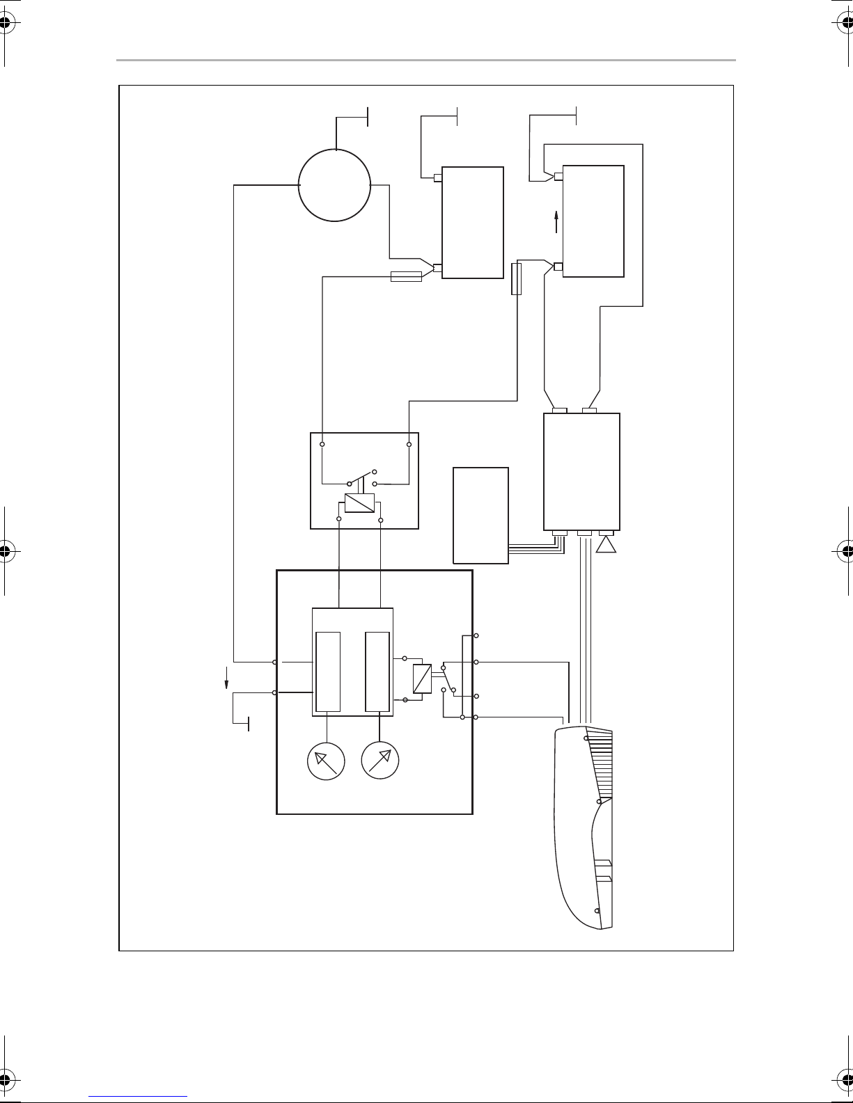
–ECL-76: fig.1, page 3
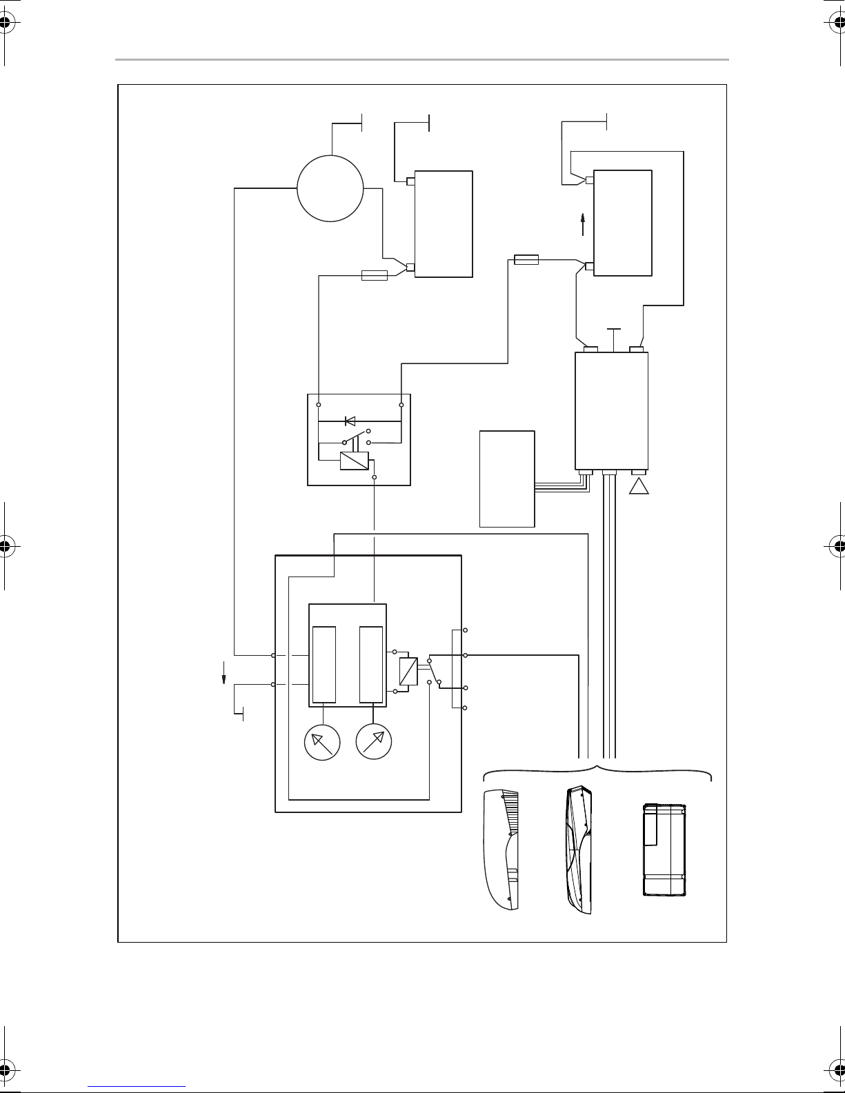
– ECL-102: fig. 2, page 4
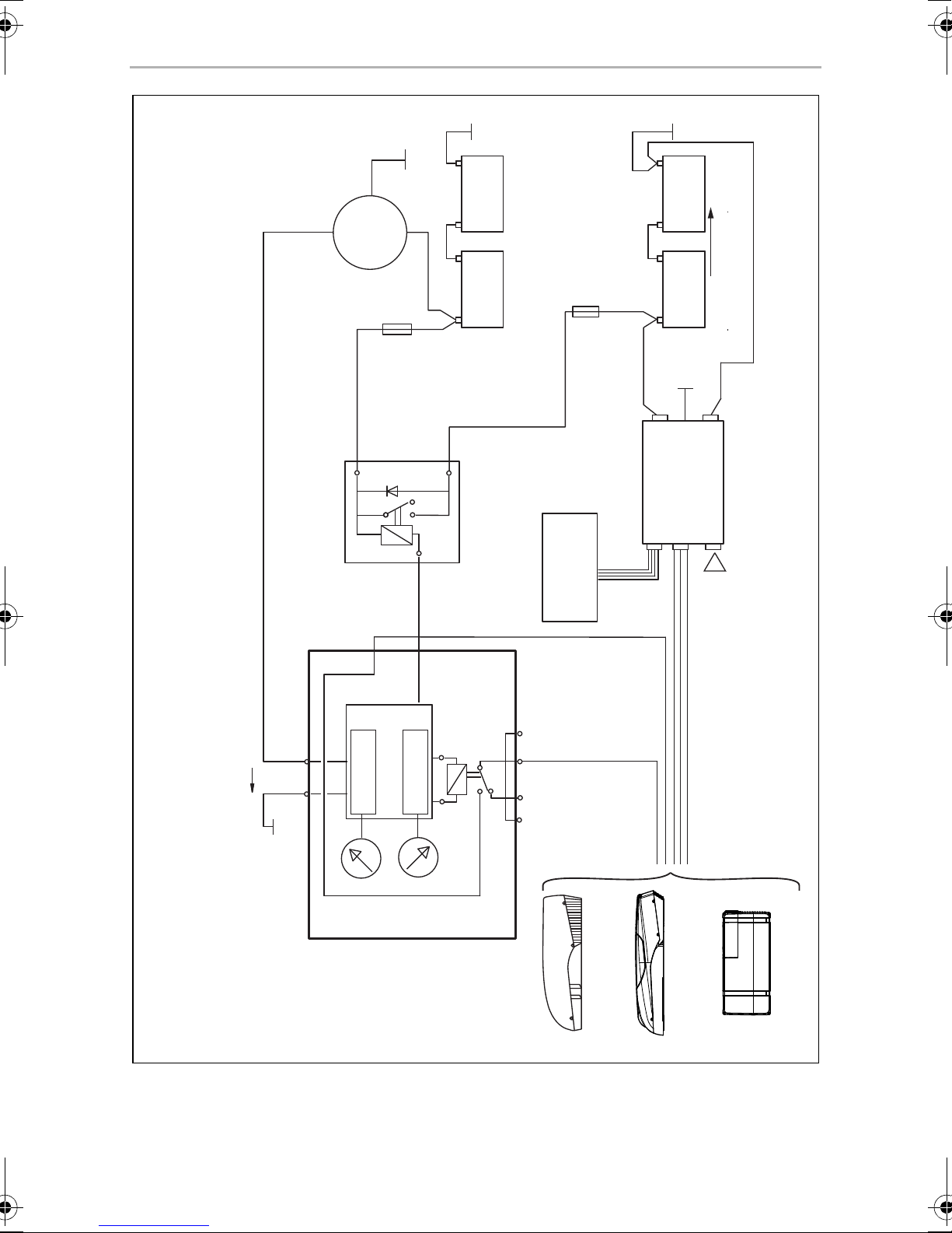
– ECL-103: fig. 3, page 5
Key for circuit diagrams in fig. 1, page 3 to fig. 3, page 5
Characters in
circuit diagram
A Starter battery
B Consumer unit battery
C Remote control
D Ua: switch-off voltage
E Ue: switch-on voltage
FFuse
Explanation
6.1 How the DC kit functions
The DC kit measures the light system voltage UD+ and compares this value against
the value of the switch-on voltage Ue.
The voltage value Ue can be adjusted for ECL-76 and ECL-102 (12.5 V – 14.0 V). For
ECL-103, the voltage value Ue is 26.6 V.
16
Page 17

EN
DC-Kit PP12, DSP-T12/24 Technical description
Supply from the battery with motor switched on
If the light system voltage exceeds the voltage value Ue (UD+ > Ue), relay contact
Batt. 1/Batt. 2 of the power relay closes. The starter battery and the consumer
battery are therefore connected in parallel with low resistance and are charged
together by the light system. In addition, the contact I2/I4 opens. This activates the
air conditioning unit.
If the light system voltage falls below the switch-off value Ua for the charging current
distributor due to the high load from the air conditioning unit, relay contact Batt. 1/
Batt. 2 opens and the parallel connection between the starter battery and the consumer battery ends. The light system now charges the starter battery. If the vehicle
has a connecting cable between the two batteries, the consumer battery is also
charged.
In addition, the contact I2/I4 closes. This switches off the compressor of the air
conditioning unit. The air conditioning unit fan and the inverter remain in operation.
The lower limit value Ua can be adjusted for ECL-76 and ECL-102 (10.5 V – 12.5 V).
For ECL-103, the voltage value Ua is 23.4 V.
As soon as the voltage in the consumer battery has reached the switch-on value Ue
for the charging current distributor, the compressor of the air conditioning unit
switches on again.
If the voltage in the consumer battery drops further and falls below the switch-off
point for the inverter, the inverter switches off.
Supply from the battery with motor switched off
If the vehicle engine is switched off (UD+ = 0 V), relay contact Batt. 1/Batt. 2 and
relay contact I2/I4 are open. The air conditioning unit can be operated and only
takes power from the consumer battery. If the battery voltage falls below
Ubatt = 10.5 V/21 V, the inverter switches off. There is no longer any voltage at
the corresponding socket and the air conditioning unit switches off.
As soon as the power from the consumer battery reaches the inverter's switch-on
point, the socket is supplied with voltage again. The air conditioning unit has to be
switched back on manually.
17
Page 18
EN
Technical description DC-Kit PP12, DSP-T12/24
6.2 DC-Kit PP12
• Air conditioner: FreshJet1100
• Circuit diagram: fig. 1, page 3
• Charging current distributor: ECL-76
• Inverter: PerfectPower PP1002
6.3 DC-Kit DSP-T12
• Air conditioning units:
– FreshJet1100/1700/2200/2700/3200
– FreshLight1600/2200
– FreshWell3000
• Circuit diagram: fig. 2, page 4
• Charging current distributor: ECL-102
• Inverter: SinePower DSP1812T
6.4 DC-Kit DSP-T24
• Air conditioning units:
– FreshJet1100/1700/2200/2700/3200
– FreshLight1600/2200
– FreshWell3000
• Circuit diagram: fig. 3, page 5
• Charging current distributor: ECL-103
• Inverter: SinePower DSP1824T
18
Page 19
EN
DC-Kit PP12, DSP-T12/24 Installing and connecting the DC kit
7 Installing and connecting the DC kit
WARNING!
!
A
• The DC kit may only be installed by specialist companies.
• To prevent the risk of short circuits, always disconnect the negative
terminal of the vehicle’s electrical system before working on the vehicle’s electrical system.
If the vehicle has a consumer battery, its negative terminal should
also be disconnected.
• The minimum cable cross sections are shown in the following diagrams:
–ECL-76: fig.1, page 3
–ECL-102: fig.2, page 4
–ECL-103: fig.3, page 5
NOTICE!
• Make sure that you route the on/off cable away from live power
cables.
• When installing, observe the information in the installation and
operating manual for the components supplied and your Dometic air
conditioner.
Observe the following instructions when selecting the location for installing the
components:
• Make sure the cables are of the correct length.
• Choose a well-ventilated installation location near the supply battery.
7.1 Preparing the installation
➤ Disconnect the following voltage supplies in the vehicle:
– negative battery terminal
– external voltage supply
7.2 Installing components
➤ Install the charging current distributor.
Attach the charging current distributor and the corresponding relay so that they
are installed firmly, are dry and well ventilated, ideally in the direct vicinity of the
inverter.
➤ Install the inverter.
19
Page 20
EN
Installing and connecting the DC kit DC-Kit PP12, DSP-T12/24
➤ Install the remote control.
DANGER! Electric shock!
D
Only connect the battery once you have the completed all the installation work and you are certain it has been done properly.
7.3 Connecting air conditioning unit FJ1100, FJ1700,
FJ2200, FJ2700, FJ3200
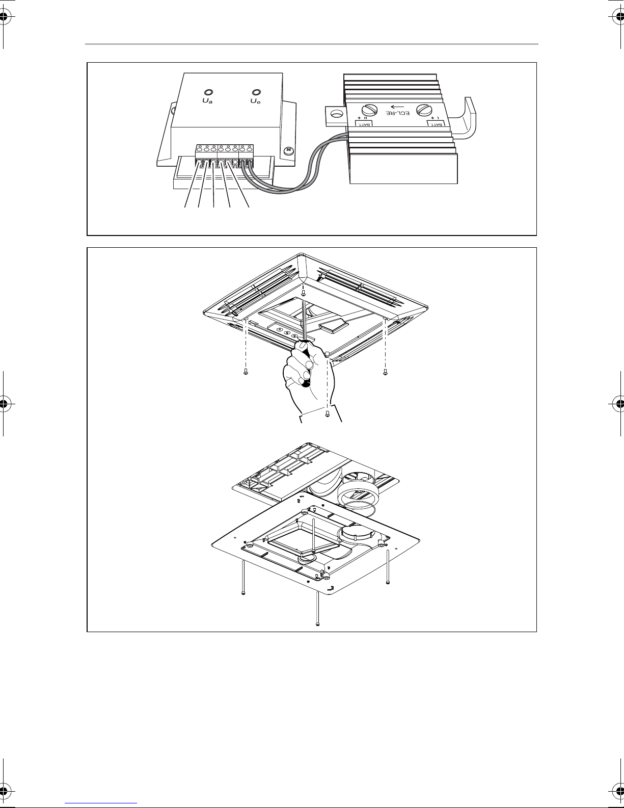
➤ Remove the air outlet unit of the air conditioner; if necessary remove the top
cover ( FreshJet) (fig. 5, page 6).
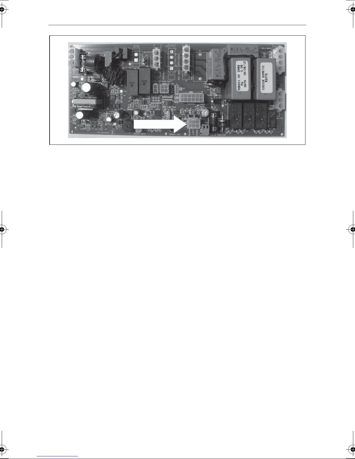
➤ Connect the on/off cable for the FreshJet to the connection socket on the circuit
board (fig. 6, page 7).
NOTE
Guide the on/off cable carefully past the fan.
I
PP12
Circuit diagram: fig. 1, page 3
➤ Route the on/off cable from the air conditioning unit to the charging current
distributor.
➤ Connect the on/off cable to connections I4 and I2 on the charging current
distributor (fig. 4, page 6).
➤ Connect the inverter adapter ( Inverter Adapter).
➤ Attach the air outlet unit of the air conditioner ( FreshJet) (fig. 5, page 6).
➤ Route the connecting cable for remote control MCR9 to the inverter and connect
it ( inverter).
DSP-T12/24
Circuit diagram:
• DC-Kit DSP-T12: fig. 2, page 4
• DC-Kit DSP-T24: fig. 3, page 5
➤ Connect the adapter cable to the on/off cable.
➤ Connect the extension cable to the adapter cable.
➤ Connect the extension cable to connections I2 and I5 on the charging current
distributor (fig. 4, page 6).
20
Page 21
EN
DC-Kit PP12, DSP-T12/24 Installing and connecting the DC kit
➤ Attach the air outlet unit of the air conditioner (fig. 5, page 6).
➤ Route the connecting cable for remote control DSP-RCT to the inverter and con-
nect it ( inverter).
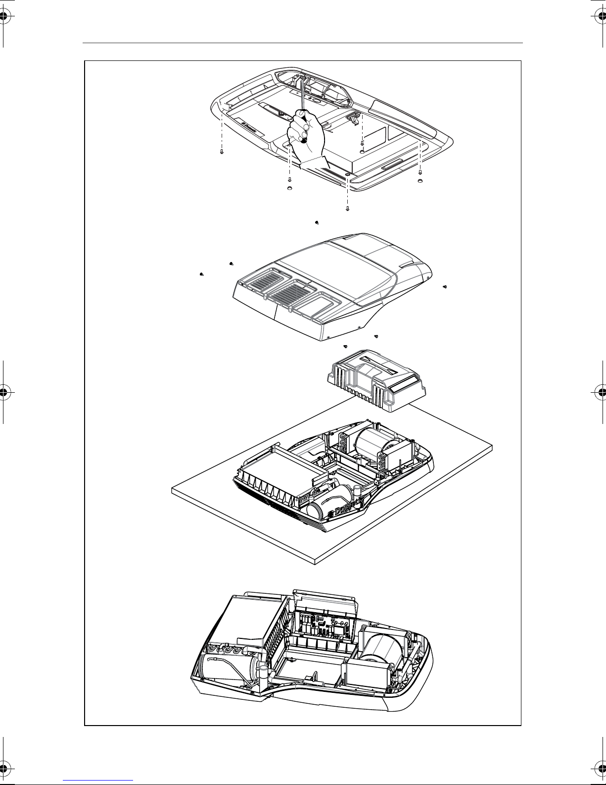
7.4 Connecting air conditioning unit FL1600, FL2200
➤ Remove the air outlet unit of the air conditioner; if necessary remove the top
cover ( FL1600, FL2200) (fig. 7, page 8).
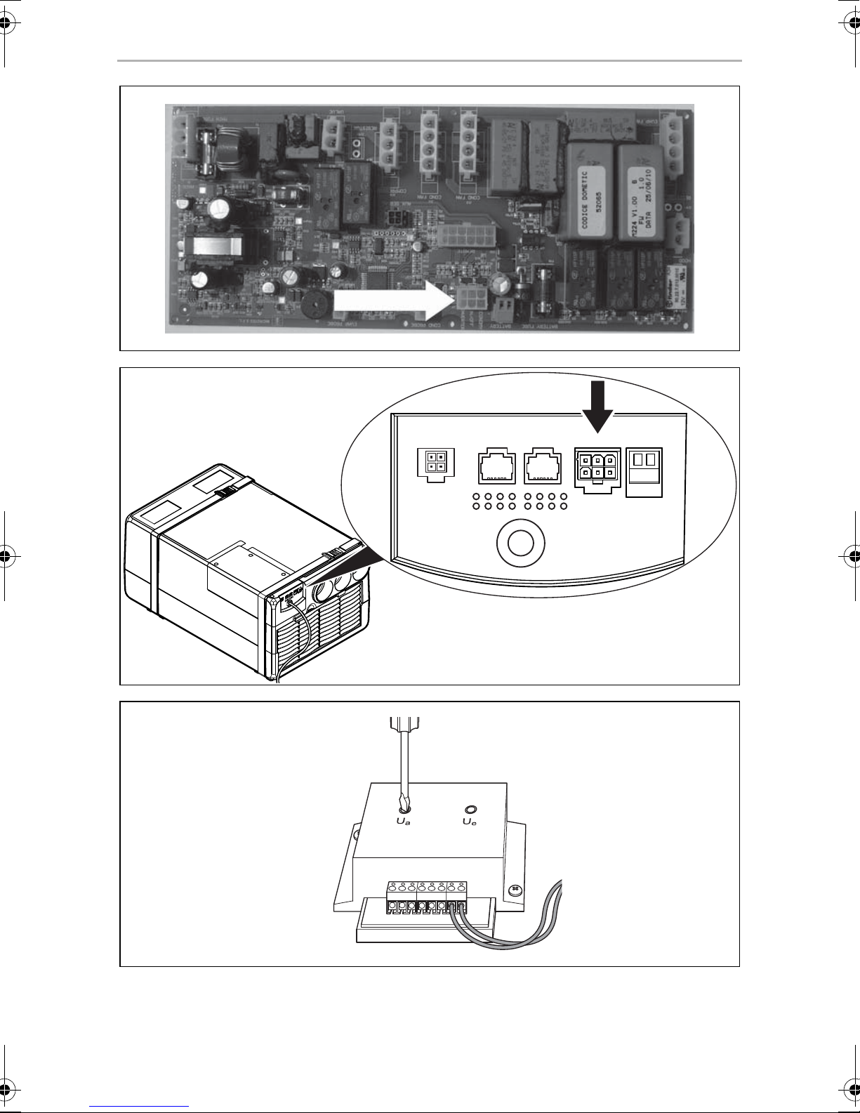
➤ Connect the on/off cable for the FreshLight to the connection socket on the
circuit board (fig. 8, page 9).
NOTE
Guide the on/off cable carefully past the fan.
I
➤ Connect the adapter cable to the on/off cable.
➤ Connect the extension cable to the adapter cable.
➤ Connect the extension cable to connections I2 and I5 on the charging current
distributor (fig. 4, page 6).
➤ Attach the air outlet unit of the air conditioner ( FreshLight) (fig. 7, page 8).
➤ Route the connecting cable for remote control DSP-RCT to the inverter and
connect it ( inverter).
7.5 Connecting air conditioning unit FW3000
➤ Connect the on/off cable for FW3000 to the connection socket on the
connector panel (fig. 9, page 9).
NOTE
Guide the on/off cable carefully past the fan.
I
➤ Connect the adapter cable to the on/off cable.
➤ Connect the extension cable to the adapter cable.
➤ Connect the extension cable to connections I2 and I5 on the charging current
distributor (fig. 4, page 6).
➤ Route the connecting cable for remote control DSP-RCT to the inverter and
connect it ( inverter).
21
Page 22
EN
Installing and connecting the DC kit DC-Kit PP12, DSP-T12/24
7.6 Connecting the DC kit to the power supply
Circuit diagram:
•DC-Kit PP12: fig.1, page 3
• DC-Kit DSP-T12: fig. 2, page 4
• DC-Kit DSP-T24: fig. 3, page 5
➤ Check that all the connections have been made in accordance with the
instructions.
➤ Check that the air conditioning unit is properly sealed.
➤ Connect the charging current distributor:
– Connect the positive terminal of the starter battery to relay connection Batt. 1.
– Connect the positive terminal of the consumer battery to relay connection
Batt. 2.
– Insert an electrical fuse (see corresponding circuit diagram for the value) in
direct proximity to the starter battery and an electrical fuse in direct proximity
to the supply battery into the positive cable.
NOTE
I
➤ Connect the AC connection of the air conditioning unit to the plug of the inverter
( inverter).
➤ Connect the positive battery cables to the batteries.
➤ Check the following are working properly:
– Check the on and off values for the charging voltage regulator
– Check the functioning of the priority circuit
– Switch on the air conditioning in driving mode ( air conditioning unit)
– Switch on the air conditioning in mains supply mode ( air conditioning unit)
• The fuse in the positive cable from the charging current distributor to
the battery can only be omitted if the lead is very short and will not
come into contact with metal.
• To connect the inverter included in the scope of delivery of the
DC kit, please refer to the instruction manual for the device.
22
Page 23
EN
DC-Kit PP12, DSP-T12/24 Using the DC kit
7.7 Adjusting the charging current distributor
(only DC-Kit PP12/DC-Kit DSP-T24)
NOTICE!
A
I
The following work must be carried out with caution and only by persons
with the necessary skills and knowledge. This is because incorrect
adjustment of the switch-on and switch-off voltages can cause the air
conditioner to malfunction and may cause the vehicle’s electrical system
to fail.
NOTE
The voltage scale shown on the charging current distributors is a guide.
If different values are set, these must be checked using a suitable voltage
measurement device. An externally adjustable laboratory power supply
can be connected to terminals GND and D+ for this purpose.
➤ Insert a screwdriver into the axis of the potentiometer (fig. 0, page 9).
Turning the axis clockwise increases the voltage threshold value, turning it
counter-clockwise reduces the voltage threshold value.
NOTE
We recommend against setting a switch-off voltage below 11.5 V.
I
8 Using the DC kit
This chapter contains information on operating the overall system. This operating
manual does not replace any information contained in the installation and operating
instructions for the individual components.
NOTE
I
Only DC-Kit 12PP: The operating noises made by the air conditioning
unit are louder during mobile air conditioning than during stationary air
conditioning. The noises are caused by using the inverter.
8.1 Switching on the system
Observe the following instructions before you switch on the system:
• Air the vehicle.
• Make sure that the ventilation slots on the air nozzles and the fan of the compo-
nents are not covered up.
23
Page 24

EN
Maintaining and cleaning the DC kit DC-Kit PP12, DSP-T12/24
• Make sure that none of the housings and cables are not damaged and that all the
insulation is intact.
• Compare the existing supply voltage against the technical data.
• Do not insert any fingers or objects into component openings.
Stationary mode: AC mains supply mode
The system is supplied from the AC mains.
Driving mode: power supply from the battery
NOTE
See also: chapter “How the DC kit functions” on page 16.
I
➤ Switch on the inverter using the remote control.
➤ Use the air conditioning unit as described in the operating manual.
8.2 Switching the system off
➤ First of all, switch off the air conditioning unit.
➤ If there are no more co nsumer units that need power, switch off the inverter using
the remote control.
9 Maintaining and cleaning the DC kit
NOTICE!
A
I
➤ Clean the charging current distributor with a damp cloth from time to time.
Do not use sharp or hard objects or cleaning agents for cleaning as these
may damage the product.
NOTE
Observe the maintenance and cleaning instructions in the operating
manuals of the individual components.
➤ Check the power supply lines for abrasion or defects regularly.
➤ Have the system checked regularly by a specialist company.
➤ If you find any faulty fuses, have the system checked by a specialist company.
24
Page 25

EN
DC-Kit PP12, DSP-T12/24 Troubleshooting
10 Troubleshooting
NOTE
I
Observe the instructions on rectifying faults in the operating manuals of
the individual components.
11 Warranty
The statutory warranty period applies. If the product is defective, please contact the
manufacturer's branch in your country (see the back of the instruction manual for the
addresses) or your retailer.
For repair and warranty processing, please include the following documents when
you send in the device:
• A copy of the receipt with purchasing date
• A reason for the claim or description of the fault
12 Disposal
➤ Place the packaging material in the appropriate recycling waste bins wherever
possible.
If you wish to finally dispose of the product, ask your local recycling centre
or specialist dealer for details about how to do this in accordance with the
M
applicable disposal regulations.
25
Page 26
EN
Technical data DC-Kit PP12, DSP-T12/24
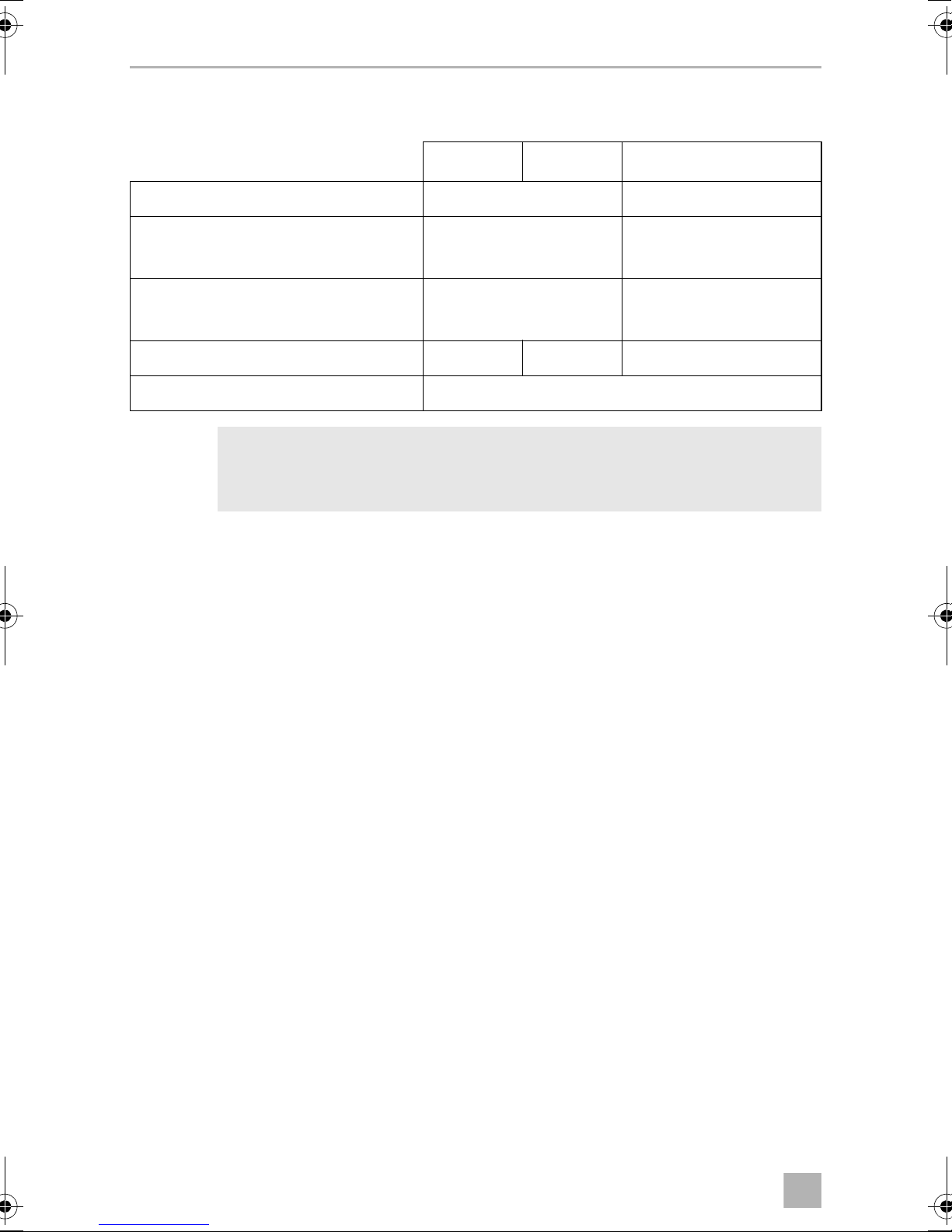
13 Technical data
ECL-76 ECL-102 ECL-103
Rated battery voltage: 12 Vg 24 Vg
Switch-off voltage Ua:
Factory setting:
Switch-on voltage Ue:
Factory setting:
Switching current via Batt. 1/Batt. 2: 75 A 100 A 100 A
Ignition off (D+ = 0 V): 0 mA
NOTE
I
You can find the technical data for the other components in the
corresponding installation and operating manuals.
10.5 V – 12.5 V
12.2 V
12 V – 14.4 V
13.3 V
23.4 V
–
26.6 V
–
26
Page 27

DE
DC-Kit PP12, DSP-T12/24
Bitte lesen Sie diese Anleitung vor Einbau und Inbetriebnahme sorgfältig
durch und bewahren Sie sie auf. Geben Sie sie im Falle einer Weitergabe
des Produktes an den Nutzer weiter.
Inhaltsverzeichnis
1 Erklärung der Symbole . . . . . . . . . . . . . . . . . . . . . . . . . . . . . . . . . . . . . . 28
2 Allgemeine Sicherheitshinweise. . . . . . . . . . . . . . . . . . . . . . . . . . . . . . 28
2.1 Allgemeine Sicherheit. . . . . . . . . . . . . . . . . . . . . . . . . . . . . . . . . . . . 29
2.2 Sicherheit bei der Installation und Reparatur . . . . . . . . . . . . . . . . . . 29
2.3 Sicherheit beim Betrieb . . . . . . . . . . . . . . . . . . . . . . . . . . . . . . . . . . 29
3Lieferumfang . . . . . . . . . . . . . . . . . . . . . . . . . . . . . . . . . . . . . . . . . . . . . . . 30
3.1 DC-Kit PP12 . . . . . . . . . . . . . . . . . . . . . . . . . . . . . . . . . . . . . . . . . . . . 30
3.2 DC-Kit DSP-T12 . . . . . . . . . . . . . . . . . . . . . . . . . . . . . . . . . . . . . . . . . .31
3.3 DC-Kit DSP-T24. . . . . . . . . . . . . . . . . . . . . . . . . . . . . . . . . . . . . . . . . . 31
4 Zielgruppe dieser Anleitung . . . . . . . . . . . . . . . . . . . . . . . . . . . . . . . . . 32
5 Bestimmungsgemäßer Gebrauch. . . . . . . . . . . . . . . . . . . . . . . . . . . . . 32
6 Technische Beschreibung . . . . . . . . . . . . . . . . . . . . . . . . . . . . . . . . . . . . 33
6.1 Funktionsweise des DC-Kits . . . . . . . . . . . . . . . . . . . . . . . . . . . . . . . 34
6.2 DC-Kit PP12 . . . . . . . . . . . . . . . . . . . . . . . . . . . . . . . . . . . . . . . . . . . . 35
6.3 DC-Kit DSP-T12 . . . . . . . . . . . . . . . . . . . . . . . . . . . . . . . . . . . . . . . . . 35
6.4 DC-Kit DSP-T24. . . . . . . . . . . . . . . . . . . . . . . . . . . . . . . . . . . . . . . . . 35
7 DC-Kit montieren und anschließen. . . . . . . . . . . . . . . . . . . . . . . . . . . . 36
7.1 Einbau vorbereiten . . . . . . . . . . . . . . . . . . . . . . . . . . . . . . . . . . . . . . 36
7.2 Komponenten montieren . . . . . . . . . . . . . . . . . . . . . . . . . . . . . . . . . 37
7.3 Klimaanlage FJ1100, FJ1700, FJ2200, FJ2700, FJ3200
anschließen . . .. . . . . . . . . . . . . . . . . . . . . . . . . . . . . . . . . . . . . . . . . 37
7.4 Klimaanlage FL1600, FL2200 anschließen . . . . . . . . . . . . . . . . . . . 38
7.5 Klimaanlage FW3000 anschließen . . . . . . . . . . . . . . . . . . . . . . . . . 39
7.6 DC-Kit elektrisch anschließen . . . . . . . . . . . . . . . . . . . . . . . . . . . . . . 39
7.7 Ladestromverteiler justieren (nur DC-Kit12PP/DC-Kit DSP-T24) . . 40
8 DC-Kit benutzen . . . . . . . . . . . . . . . . . . . . . . . . . . . . . . . . . . . . . . . . . . . . .41
8.1 Anlage einschalten . . . . . . . . . . . . . . . . . . . . . . . . . . . . . . . . . . . . . . .41
8.2 Anlage ausschalten . . . . . . . . . . . . . . . . . . . . . . . . . . . . . . . . . . . . . . .41
9 DC-Kit pflegen und warten. . . . . . . . . . . . . . . . . . . . . . . . . . . . . . . . . . . 42
27
Page 28
DE
Erklärung der Symbole DC-Kit PP12, DSP-T12/24
10 Fehlerbeseitigung. . . . . . . . . . . . . . . . . . . . . . . . . . . . . . . . . . . . . . . . . . . 42
11 Gewährleistung. . . . . . . . . . . . . . . . . . . . . . . . . . . . . . . . . . . . . . . . . . . . . 42
12 Entsorgung . . . . . . . . . . . . . . . . . . . . . . . . . . . . . . . . . . . . . . . . . . . . . . . . . 43
13 Technische Daten . . . . . . . . . . . . . . . . . . . . . . . . . . . . . . . . . . . . . . . . . . . 43
1 Erklärung der Symbole
GEFAHR!
D
!
Sicherheitshinweis: Nichtbeachtung führt zu Tod oder schwerer
Verletzung.
WARNUNG!
Sicherheitshinweis: Nichtbeachtung kann zu Tod oder schwerer
Verletzung führen.
ACHTUNG!
A
Nichtbeachtung kann zu Materialschäden führen und die Funktion des
Produktes beeinträchtigen.
HINWEIS
Ergänzende Informationen zur Bedienung des Produktes.
I
2 Allgemeine Sicherheitshinweise
Der Hersteller übernimmt in folgenden Fällen keine Haftung für Schäden:
• Montage- oder Anschlussfehler
• Beschädigungen am Produkt durch mechanische Einflüsse und falsche
Anschlussspannung
• Veränderungen am Produkt ohne ausdrückliche Genehmigung vom Hersteller
• Verwendung für andere als die in der Anleitung beschriebenen Zwecke
28
Page 29
DE
DC-Kit PP12, DSP-T12/24 Allgemeine Sicherheitshinweise
2.1 Allgemeine Sicherheit
WARNUNG!
!
• Beachten Sie auch die Sicherheitshinweise in den Montage- und
Bedienungsanleitung zu den mitgelieferten Komponenten und zu
Ihrer Dometic Klimaanlage.
• Benutzen Sie das Gerät nur zu seinem bestimmungsgemäßen
Gebrauch.
• Personen, die aufgrund ihrer physischen, sensorischen oder geistigen
Fähigkeiten oder ihrer Unerfahrenheit oder Unkenntnis nicht in der
Lage sind, das Gerät sicher zu benutzen, sollten dieses Gerät nicht
ohne Aufsicht oder Anweisung durch eine verantwortliche Person
nutzen.
• Elektrogeräte sind kein Kinderspielzeug!
Verwahren und benutzen Sie das Gerät außerhalb der Reichweite von
Kindern.
• Kinder sollten beaufsichtigt werden, um sicherzustellen, dass sie nicht
mit dem Gerät spielen.
• Die Wartung und Reparatur darf nur durch Fachbetriebe durchgeführt
werden, die mit den damit verbundenen Gefahren bzw. einschlägigen Vorschriften vertraut ist.
2.2 Sicherheit bei der Installation und Reparatur
WARNUNG!
!
2.3 Sicherheit beim Betrieb
!
• Die Installation und Reparatur des Gerätes darf ausschließlich von
Fachbetrieben durchgeführt werden, die mit den Gefahren sowie den
anzuwendenden Richtlinien und Sicherheitsvorkehrungen vertraut
sind.
WARNUNG!
Beachten Sie folgende grundsätzliche Sicherheitsmaßnahmen beim
Gebrauch von elektrischen Geräten zum Schutz vor:
•elektrischem Schlag
• Brandgefahr
•Verletzungen
29
Page 30
DE
Lieferumfang DC-Kit PP12, DSP-T12/24
• Betreiben Sie das System nur, wenn alle Gehäuse und Leitungen
unbeschädigt sind.
• Die Gleichstrom-Anschlusskabel sind für hohe Ströme ausgelegt.
Modifizieren Sie die Kabel nicht. Falls nötig, lassen Sie das nur durch
einen Fachbetrieb durchführen.
• Achten Sie darauf, dass Luftein- und Ausgänge des Geräts nicht verdeckt werden.
• Achten Sie auf gute Belüftung. Der Wechselrichter produziert Verlustwärme, die abgeführt werden muss.
• Unterbrechen Sie bei Arbeiten am Gerät immer die Stromversorgung.
3 Lieferumfang
Prüfen Sie vor Inbetriebnahme des Systems, ob alle zum Lieferumfang gehörenden
Teile vorhanden sind.
3.1 DC-Kit PP12
Menge Bezeichnung Artikelnummer
1 Ladestromverteiler ECL-76 9600000483
1 Wechselrichter mit Vorrangschaltung PP1002 9600000022
1Anschlusskabel
schwarze Zuleitung (35 mm², 1,5 m lang)
rote Zuleitung (35 mm², 1,5 m lang)
1 Sensing Cable für FreshJet/FreshLight 4441300221
1 Wechselrichter-Adapter 9103530084
1 Fernbedienung für den Wechselrichter MCR9 9600000091
1 Montage- und Bedienungsanleitung 4445101952
9600000270
30
Page 31

DE
DC-Kit PP12, DSP-T12/24 Lieferumfang
3.2 DC-Kit DSP-T12
Menge Bezeichnung Artikelnummer
1 Ladestromverteiler ECL-102 9600000547
1 Wechselrichter DSP1812T mit Vorrangschaltung 9600002553
1 Fernbedienung für den Wechselrichter DSP-RCT
(einschließlich Anschlusskabel)
1Anschlusskabel
schwarze Zuleitung (35 mm², 1,5 m lang)
rote Zuleitung (35 mm², 1,5 m lang)
1 Adapterkabel für FreshJet/FreshLight/FreshWell 4441300221
1 Verlängerungskabel 4441300124
1 Montage- und Bedienungsanleitung 4445101954
9600002564
4441300120
4441300119
3.3 DC-Kit DSP-T24
Menge Bezeichnung Artikelnummer
1 Ladestromverteiler ECL-103 9600000548
1 Wechselrichter DSP1824T mit Vorrangschaltung 9600002554
1 Fernbedienung für den Wechselrichter DSP-RCT
(einschließlich Anschlusskabel)
9600002564
1Anschlusskabel
schwarze Zuleitung (35 mm², 1,5 m lang)
rote Zuleitung (35 mm², 1,5 m lang)
1 Adapterkabel für FreshJet/FreshLight/FreshWell 4441300221
1 Verlängerungskabel 4441300124
1 Montage- und Bedienungsanleitung 4445101956
4441300120
4441300119
31
Page 32

DE
Zielgruppe dieser Anleitung DC-Kit PP12, DSP-T12/24
4 Zielgruppe dieser Anleitung
Die Einbauinformationen in dieser Anleitung wenden sich ausschließlich an Fachbetriebe, die mit den anzuwendenden Richtlinien und Sicherheitsvorkehrungen
beim Einbau von Fahrzeugzubehörteilen vertraut sind.
Alle übrigen Kapitel wenden sich auch an die Benutzer des Gerätes.
5 Bestimmungsgemäßer Gebrauch
Das Erweiterungskit DC-Kit ist geeignet, um die folgenden Dometic Klimaanlagen
für den Gleichstrom-Fahrbetrieb aufzurüsten:
• DC-Kit PP12 (Art.-Nr. 9100300003), 12 Vg
– FJ1100
• DC-Kit DSP-T12 (Art.-Nr. 9100300002), 12 Vg
– FJ1100, FJ1700, FJ2200, FJ2700, FJ3200
– FL1600, FL2200
–FW3000
• DC-Kit DSP-T24 (Art.-Nr. 9100300073), 24 Vg
– FJ1100, FJ1700, FJ2200, FJ2700, FJ3200
– FL1600, FL2200
–FW3000
Falls die Klimaanlage nicht über eine Wärmepumpe verfügt (siehe Anleitung der
Klimaanlage), darf der Wechselrichter nur für den Kühleinsatz der Klimaanlage verwendet werden, nicht für den Heizbetrieb, da die Heizelemente mehr Strom aufnehmen als der Wechselrichter im Dauerbetrieb erzeugen kann.
32
Page 33

DE
DC-Kit PP12, DSP-T12/24 Technische Beschreibung
6 Technische Beschreibung
Das Erweiterungskit besteht aus den folgenden Komponenten:
• Der Ladestromverteiler mit Unterspannungsschutz regelt die Stromverteilung
zwischen Starterbatterie, Versorgungsbatterie und Lichtmaschine sowie den
Betrieb der Klimaanlage. Er verhindert eine Überlastung der Batterien und der
Bordelektronik.
• Der Wechselrichter versorgt die Klimaanlage mit der erforderlichen Eingangsspannung von 230 Vw. Der Wechselrichter generiert diese 230-V-Eingangsspannung aus dem Gleichstrom-Bordnetz des Fahrzeugs.
Die integrierte Vorrangschaltung dient zur Spannungsverteilung in Fahrzeugen
mit zwei möglichen Stromquellen. Wenn am Gerät eine Festnetz-Spannung
anliegt, wird diese vorrangig genutzt. So wird sichergestellt, dass die begrenzte
Energie der Batterie nicht unnötig verbraucht wird. Wenn keine FestnetzSpannung anliegt, wird das Gleichstrom-Bordnetz genutzt.
• Durch die Fernbedienung kann der Wechselrichter ein- und ausgeschaltet
werden.
Der Ladestromverteiler besitzt zwei Relais, die wie folgt benutzt werden:
• Leistungsrelais (Batt. 1/Batt. 2)
zur Verbindung von Starter- und Verbraucherbatterie
• Steuerrelais
zum Ein- und Ausschalten des Kompressors
–ECL-76: Abb.1, Seite 3
– ECL-102: Abb. 2, Seite 4
– ECL-103: Abb. 3, Seite 5
Legende zu den Schaltplänen in Abb. 1, Seite 3 bis Abb. 3, Seite 5
Zeichen in
Schaltplan
A Starterbatterie
B Verbraucherbatterie
C Fernbedienung
Erklärung
D Ua: Ausschaltspannung
E Ue: Einschaltspannung
F Schmelzsicherung
33
Page 34

DE
Technische Beschreibung DC-Kit PP12, DSP-T12/24
6.1 Funktionsweise des DC-Kits
Das DC-Kit misst die Lichtmaschinenspannung UD+ und vergleicht diesen Wert mit
der Einschaltspannung Ue.
Der Spannungswert Ue ist bei ECL-76 und ECL-102 einstellbar (12,5 V – 14,0 V). Bei
ECL-103 beträgt der Spannungswert Ue 26,6 V.
Versorgung durch die Batterie bei gestartetem Motor
Wenn die Lichtmaschinenspannung den Spannungswert Ue überschreitet
(UD+ > Ue), wird der Relaiskontakt Batt. 1/Batt. 2 des Leistungsrelais geschlossen.
Starterbatterie und Verbraucherbatterie werden somit niederohmig parallel verbunden und gemeinsam von der Lichtmaschine geladen. Außerdem wird Kontakt
I2/I4 geöffnet. Dies aktiviert die Klimaanlage.
Wenn die Lichtmaschinenspannung aufgrund der hohen Belastung durch die Klimaanlage den Ausschaltwert Ua des Ladestromverteilers unterschreitet, wird Relaiskontakt Batt. 1/Batt. 2 geöffnet und die Parallelschaltung von Starterbatterie und
Verbraucherbatterie aufgehoben. Die Lichtmaschine lädt nun die Starterbatterie auf.
Besitzt das Fahrzeug eine Verbindungsleitung zwischen den beiden Batterien, wird
auch die Verbraucherbatterie geladen.
Außerdem wird Kontakt I2/I4 geschlossen. Dadurch wird der Kompressor der
Klimaanlage abgeschaltet. Der Lüfter der Klimaanlage und der Wechselrichter
bleiben weiterhin in Betrieb.
Der untere Grenzwert Ua ist bei ECL-76 und ECL-102 einstellbar (10,5 V – 12,5 V).
Bei ECL-103 beträgt der Spannungswert Ua 23,4 V.
Sobald die Spannung der Verbraucherbatterie den Einschaltwert Ue des Ladestromverteilers erreicht, wird der Kompressor der Klimaanlage wieder eingeschaltet.
Falls die Spannung der Verbraucherbatterie weiter fällt und unter den Ausschaltwert
des Wechselrichters sinkt, wird der Wechselrichter abgeschaltet.
Versorgung durch die Batterie bei ausgeschaltetem Motor
Wenn der Fahrzeugmotor ausgeschaltet ist (UD+ = 0 V), sind Relaiskontakt Batt. 1/
Batt. 2 und Relaiskontakt I2/I4 geöffnet. Die Klimaanlage kann betrieben werden
und belastet nur die Verbraucherbatterie. Bei Unterschreiten einer Batteriespannung Ubatt = 10,5 V/21 V schaltet der Wechselrichter aus. An seiner Steckdose
liegt keine Spannung mehr an, und die Klimaanlage schaltet ab.
Sobald die Spannung der Verbraucherbatterie den Einschaltwert des Wechselrichters erreicht, liegt an seiner Steckdose wieder Spannung an. Die Klimaanlage
muss manuell wieder eingeschaltet werden.
34
Page 35

DE
DC-Kit PP12, DSP-T12/24 Technische Beschreibung
6.2 DC-Kit PP12
• Klimaanlage: FreshJet1100
• Schaltplan: Abb. 1, Seite 3
• Ladestromverteiler: ECL-76
• Wechselrichter: PerfectPower PP1002
6.3 DC-Kit DSP-T12
•Klimaanlagen:
– FreshJet1100/1700/2200/2700/3200
– FreshLight1600/2200
– FreshWell3000
• Schaltplan: Abb. 2, Seite 4
• Ladestromverteiler: ECL-102
• Wechselrichter: SinePower DSP1812T
6.4 DC-Kit DSP-T24
•Klimaanlagen:
– FreshJet1100/1700/2200/2700/3200
– FreshLight1600/2200
– FreshWell3000
• Schaltplan: Abb. 3, Seite 5
• Ladestromverteiler: ECL-103
• Wechselrichter: SinePower DSP1824T
35
Page 36

DE
DC-Kit montieren und anschließen DC-Kit PP12, DSP-T12/24
7 DC-Kit montieren und anschließen
WARNUNG!
!
A
• Der Einbau des DC-Kits darf ausschließlich von Fachbetrieben
durchgeführt werden.
• Klemmen Sie wegen der Kurzschlussgefahr vor Arbeiten an der
Fahrzeugelektrik immer den Minuspol der Fahrzeugbatterie ab.
Bei Fahrzeugen mit Verbraucherbatterie müssen Sie an dieser
ebenfalls den Minuspol abklemmen.
• Die Mindest-Kabelquerschnitte sind in folgenden Abbildungen
aufgeführt:
– ECL-76: Abb. 1, Seite 3
–ECL-102: Abb.2, Seite 4
–ECL-103: Abb.3, Seite 5
ACHTUNG!
• Achten Sie darauf, dass Sie das Ein-/Ausschaltkabel entfernt von
leistungsführenden Stromkabeln verlegen.
• Beachten Sie beim Einbau auch die Informationen in den Montageund Bedienungsanleitung zu den mitgelieferten Komponenten und
zu Ihrer Dometic Klimaanlage.
Beachten Sie folgende Hinweise bei der Wahl der Montageorte für die
Komponenten:
• Beachten Sie die Kabellängen.
• Wählen Sie einen gut belüfteten Montageort nahe der Versorgungsbatterie.
7.1 Einbau vorbereiten
➤ Folgende Spannungsversorgungen des Fahrzeuges lösen:
– Minuspol der Batterie
– Externe Spannungsversorgung
36
Page 37

DE
DC-Kit PP12, DSP-T12/24 DC-Kit montieren und anschließen
7.2 Komponenten montieren
➤ Ladestromverteiler montieren.
Den Ladestromverteiler und das zugehörige Relais so befestigen, dass sie fest
montiert sowie trocken und gut belüftet sind, idealerweise in der direkten Nähe
zum Wechselrichter.
➤ Wechselrichter montieren.
➤ Fernbedienung montieren.
GEFAHR! Stromschlag!
D
Schließen Sie die Batterieanschlüsse erst dann an, wenn die gesamte
Installation abgeschlossen ist und Sie sich von der fehlerfreien
Installation überzeugt haben.
7.3 Klimaanlage FJ1100, FJ1700, FJ2200, FJ2700, FJ3200
anschließen ...
➤ Luftauslasseinheit der Klimaanlage entfernen, ggf. die obere Abdeckhaube ent-
fernen ( FreshJet) (Abb. 5, Seite 6).
➤ Ein-/Ausschaltkabel der FreshJet mit dem Steckanschluss auf der Platine
verbinden (Abb. 6, Seite 7).
HINWEIS
Führen Sie das Ein-/Ausschaltkabel vorsichtig am Lüfter vorbei.
I
PP12
Schaltplan: Abb. 1, Seite 3
➤ Ein-/Ausschaltkabel von der Klimaanlage zum Ladestromverteiler verlegen.
➤ Ein-/Ausschaltkabel mit den Anschlüssen I4 und I2 des Ladestromverteilers
verbinden (Abb. 4, Seite 6).
➤ Wechselrichter-Adapter anschließen ( Inverter Adapter).
➤ Luftauslasseinheit der Klimaanlage befestigen ( FreshJet) (Abb. 5, Seite 6).
➤ Verbindungskabel der Fernbedienung MCR 9 zum Wechselrichter verlegen und
anschließen ( Wechselrichter).
37
Page 38

DE
DC-Kit montieren und anschließen DC-Kit PP12, DSP-T12/24
DSP-T12/24
Schaltplan:
• DC-Kit DSP-T12: Abb. 2, Seite 4
• DC-Kit DSP-T24: Abb. 3, Seite 5
➤ Adapterkabel mit dem Ein-/Ausschaltkabel verbinden.
➤ Verlängerungskabel mit dem Adapterkabel verbinden.
➤ Verlängerungskabel mit den Anschlüssen I2 und I5 des Ladestromverteilers ver-
binden (Abb. 4, Seite 6).
➤ Luftauslasseinheit der Klimaanlage befestigen (Abb. 5, Seite 6).
➤ Verbindungskabel der Fernbedienung DSP-RCT zum Wechselrichter verlegen
und anschließen ( Wechselrichter).
7.4 Klimaanlage FL1600, FL2200 anschließen
➤ Luftauslasseinheit der Klimaanlage entfernen, ggf. die obere Abdeckhaube ent-
fernen ( FL1600, FL2200) (Abb. 7, Seite 8).
➤ Ein-/Ausschaltkabel der FreshLight mit dem Steckanschluss auf der Platine ver-
binden (Abb. 8, Seite 9).
HINWEIS
Führen Sie das Ein-/Ausschaltkabel vorsichtig am Lüfter vorbei.
I
➤ Adapterkabel mit dem Ein-/Ausschaltkabel verbinden
➤ Verlängerungskabel mit dem Adapterkabel verbinden.
➤ Verlängerungskabel mit den Anschlüssen I2 und I5 des Ladestromverteilers ver-
binden (Abb. 4, Seite 6).
➤ Luftauslasseinheit der Klimaanlage befestigen ( FreshLight) (Abb. 7, Seite 8).
➤ Verbindungskabel der Fernbedienung DSP-RCT zum Wechselrichter verlegen
und anschließen ( Wechselrichter).
38
Page 39

DE
DC-Kit PP12, DSP-T12/24 DC-Kit montieren und anschließen
7.5 Klimaanlage FW3000 anschließen
➤ Ein-/Ausschaltkabel für FW3000 mit dem Steckanschluss am Anschlussfeld ver-
binden (Abb. 9, Seite 9).
HINWEIS
Führen Sie das Ein-/Ausschaltkabel vorsichtig am Lüfter vorbei.
I
➤ Adapterkabel mit dem Ein-/Ausschaltkabel verbinden
➤ Verlängerungskabel mit dem Adapterkabel verbinden.
➤ Verlängerungskabel mit den Anschlüssen I2 und I5 des Ladestromverteilers ver-
binden (Abb. 4, Seite 6).
➤ Verbindungskabel der Fernbedienung DSP-RCT zum Wechselrichter verlegen
und anschließen ( Wechselrichter).
7.6 DC-Kit elektrisch anschließen
Schaltplan:
• DC-Kit PP 12: Abb. 1, Seite 3
• DC-Kit DSP-T12: Abb. 2, Seite 4
• DC-Kit DSP-T24: Abb. 3, Seite 5
➤ Prüfen, ob alle Anschlüsse gemäß den Anweisungen und Vorschriften ange-
schlossen sind.
➤ Prüfen, ob die Klimaanlage ordnungsgemäß verschlossen ist.
➤ Ladestromverteiler anschließen:
– Den Pluspol der Starterbatterie mit dem Relais-Anschluss Batt. 1 verbinden.
– Den Pluspol der Verbraucherbatterie mit dem Relais-Anschluss Batt. 2
verbinden.
– In die Plus-Leitung jeweils eine elektrische Schmelzsicherung (Wert siehe
zugehörigen Schaltplan) in direkter Nähe zur Starterbatterie und
Versorgungsbatterie einsetzen.
HINWEIS
I
• Auf die Sicherung in der Plus-Leitung vom Ladestromverteiler zur
Batterie kann nur verzichtet werden, wenn die Leitung sehr kurz ist
und nicht mit Metall in Berührung kommen kann.
• Zum Anschluss des Wechselrichters im Lieferumfang des DC-Kits
beachten Sie bitte die Anleitung zum Gerät.
39
Page 40

DE
DC-Kit montieren und anschließen DC-Kit PP12, DSP-T12/24
➤ Wechselstrom-Anschluss der Klimaanlage mit dem Stecker des Wechselrichters
verbinden ( Wechselrichter).
➤ Pluskabel der Batterieleitungen an die Batterien anschließen.
➤ Installation auf korrekte Funktion prüfen:
– Ein- und Ausschaltwerte des Ladespannungsreglers prüfen
– Funktion der Vorrangschaltung prüfen
– Im Fahrbetrieb die Klimaanlage einschalten ( Klimaanlage)
– Im Netzbetrieb die Klimaanlage einschalten ( Klimaanlage)
7.7 Ladestromverteiler justieren
(nur DC-Kit12PP/DC-Kit DSP-T24)
ACHTUNG!
A
Die nachfolgend beschriebenen Arbeiten sollten nur mit Bedacht und
besonderer Kenntnis erledigt werden, da es bei falscher Justierung von
Ein- und Ausschaltspannungen zu Fehlfunktionen der Klimaanlage
kommen kann und die Fahrzeugelektrik versagen kann.
HINWEIS
I
➤ Führen Sie den Schraubendreher in die Achse des Potentiometers ein (Abb. 0,
Seite 9).
Eine Drehung im Uhrzeigersinn erhöht den Spannungsschwellenwert, eine
Drehung gegen den Uhrzeigersinn verringert den Spannungsschwellenwert.
Die auf den Ladestromverteilern abgebildete Spannungsskala ist eine
Orientierungshilfe. Sollen andere Werte eingestellt werden, so sind
diese mit einem geeigneten Spannungsmessgerät zu prüfen. Hierzu
kann ein extern einstellbares Labornetzteil an die Klemmen GND und
D+ angeschlossen werden.
HINWEIS
Eine Abschaltspannung unterhalb 11,5 V ist nicht zu empfehlen.
I
40
Page 41

DE
DC-Kit PP12, DSP-T12/24 DC-Kit benutzen
8 DC-Kit benutzen
In diesem Kapitel finden Sie Hinweise zur Bedienung des Gesamtsystems. Diese
Bedienungsanleitung ersetzt nicht die Informationen in den Montage- und
Bedienungsanleitungen der einzelnen Komponenten.
HINWEIS
I
8.1 Anlage einschalten
Beachten Sie folgende Hinweise, bevor Sie das System einschalten:
• Lüften Sie das Fahrzeug.
• Stellen Sie sicher, dass die Lüftungsöffnungen der Luftdüsen und Lüfter der
Komponenten nicht verdeckt sind.
Nur DC-Kit12PP: Bei der Fahrklimatisierung sind die Betriebsgeräusche der Klimaanlage etwas lauter als bei der Standklimatisierung. Die
Geräuschentwicklung entsteht durch den Einsatz des Wechselrichters.
• Stellen Sie sicher, dass alle Gehäuse und Kabel unbeschädigt sind und dass alle
Isolierungen intakt sind.
• Vergleichen Sie die vorhandene Versorgungsspannung mit den technischen
Daten.
• Stecken Sie keine Finger oder Gegenstände in Öffnungen von Komponenten.
Standbetrieb: Wechselstrom-Netzbetrieb
Das System wird vom Wechselstrom-Netz versorgt.
Fahrbetrieb: Versorgung durch die Batterie
HINWEIS
Beachten Sie auch: Kapitel „Funktionsweise des DC-Kits“ auf Seite 34.
I
➤ Schalten Sie den Wechselrichter über die Fernbedienung ein.
➤ Verwenden Sie die Klimaanlage wie in deren Bedienungsanleitung beschrieben.
8.2 Anlage ausschalten
➤ Schalten Sie zuerst die Klimaanlage aus.
➤ Wenn Sie keine weiteren Verbraucher mit Strom versorgen, schalten Sie den
Wechselrichter über die Fernbedienung aus.
41
Page 42

DE
DC-Kit pflegen und warten DC-Kit PP12, DSP-T12/24
9 DC-Kit pflegen und warten
ACHTUNG!
A
I
➤ Reinigen Sie den Ladestromverteiler gelegentlich mit einem feuchten Tuch.
➤ Prüfen Sie in regelmäßigen Abständen die Stromleitungen auf Scheuerstellen
oder Defekte.
➤ Lassen Sie die Anlage in regelmäßigen Abständen von einem Fachbetrieb
kontrollieren.
Keine scharfen oder harten Gegenstände oder Reinigungsmittel zur
Reinigung verwenden, da dies zu einer Beschädigung des Produktes
führen kann.
HINWEIS
Beachten Sie die Pflege- und Reinigungsanweisungen in den
Bedienungsanleitungen der einzelnen Komponenten.
➤ Wenn Sie defekte Schmelzsicherungen finden, lassen Sie die Anlage von einem
Fachbetrieb kontrollieren.
10 Fehlerbeseitigung
HINWEIS
I
Beachten Sie die Hinweise zur Fehlerbeseitigung in den Bedienungsanleitungen der einzelnen Komponenten.
11 Gewährleistung
Es gilt die gesetzliche Gewährleistungsfrist. Sollte das Produkt defekt sein, wenden
Sie sich bitte an die Niederlassung des Herstellers in Ihrem Land (Adressen siehe
Rückseite der Anleitung) oder an Ihren Fachhändler.
Zur Reparatur- bzw. Gewährleistungsbearbeitung müssen Sie folgende Unterlagen
mitschicken:
• eine Kopie der Rechnung mit Kaufdatum,
• einen Reklamationsgrund oder eine Fehlerbeschreibung.
42
Page 43

DE
DC-Kit PP12, DSP-T12/24 Entsorgung
12 Entsorgung
➤ Geben Sie das Verpackungsmaterial möglichst in den entsprechenden
Recycling-Müll.
Wenn Sie das Produkt endgültig außer Betrieb nehmen, informieren Sie
sich bitte beim nächsten Recyclingcenter oder bei Ihrem Fachhändler
M
über die zutreffenden Entsorgungsvorschriften.
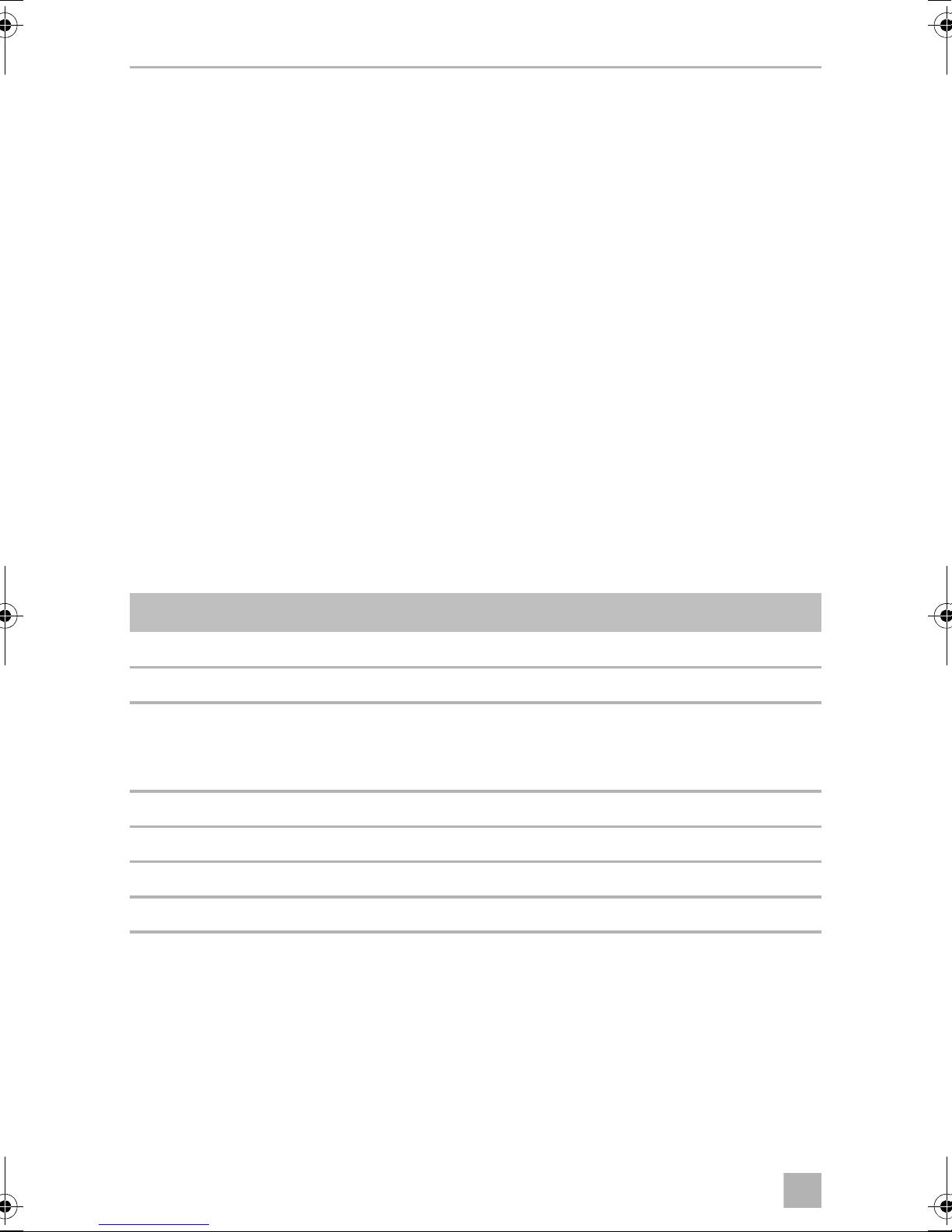
13 Technische Daten
ECL-76 ECL-102 ECL-103
Batterie-Nennspannung: 12 Vg 24 Vg
Ausschaltspannung Ua:
Werkseinstellung:
Einschaltspannung Ue:
Werkseinstellung:
Schaltstrom über Batt. 1/Batt. 2: 75 A 100 A 100 A
Zündung aus (D+ = 0 V): 0 mA
HINWEIS
I
Die technischen Daten der weiteren Komponenten finden Sie in den
zugehörigen Montage- und Bedienungsanleitungen.
10,5 V – 12,5 V
12,2 V
12 V – 14,4 V
13,3 V
23,4 V
–
26,6 V
–
43
Page 44

FR
DC-Kit PP12, DSP-T12/24
Veuillez lire attentivement cette notice avant le montage et la mise en
service. Veuillez ensuite la conserver. En cas de passer le produit, veuillez
le transmettre au nouvel acquéreur.
Sommaire
1 Description des symboles. . . . . . . . . . . . . . . . . . . . . . . . . . . . . . . . . . . . 45
2 Consignes générales de sécurité . . . . . . . . . . . . . . . . . . . . . . . . . . . . . 45
2.1 Sécurité générale . . . . . . . . . . . . . . . . . . . . . . . . . . . . . . . . . . . . . . . 46
2.2 Sécurité lors du montage et des réparations . . . . . . . . . . . . . . . . . . 46
2.3 Sécurité lors du fonctionnement . . . . . . . . . . . . . . . . . . . . . . . . . . . 46
3 Contenu de la livraison . . . . . . . . . . . . . . . . . . . . . . . . . . . . . . . . . . . . . . 47
3.1 DC-Kit PP12 . . . . . . . . . . . . . . . . . . . . . . . . . . . . . . . . . . . . . . . . . . . . 47
3.2 DC-Kit DSP-T12 . . . . . . . . . . . . . . . . . . . . . . . . . . . . . . . . . . . . . . . . . 48
3.3 DC-Kit DSP-T24. . . . . . . . . . . . . . . . . . . . . . . . . . . . . . . . . . . . . . . . . 48
4 Groupe cible de ce manuel . . . . . . . . . . . . . . . . . . . . . . . . . . . . . . . . . . . 49
5Usage conforme . . . . . . . . . . . . . . . . . . . . . . . . . . . . . . . . . . . . . . . . . . . . 49
6 Description technique . . . . . . . . . . . . . . . . . . . . . . . . . . . . . . . . . . . . . . . 50
6.1 Fonctionnement du DC-Kit . . . . . . . . . . . . . . . . . . . . . . . . . . . . . . . . .51
6.2 DC-Kit PP12 . . . . . . . . . . . . . . . . . . . . . . . . . . . . . . . . . . . . . . . . . . . . 52
6.3 DC-Kit DSP-T12 . . . . . . . . . . . . . . . . . . . . . . . . . . . . . . . . . . . . . . . . . 52
6.4 DC-Kit DSP-T24. . . . . . . . . . . . . . . . . . . . . . . . . . . . . . . . . . . . . . . . . 52
7 Montage et raccordement du DC kit . . . . . . . . . . . . . . . . . . . . . . . . . . 53
7.1 Préparation au montage . . . . . . . . . . . . . . . . . . . . . . . . . . . . . . . . . . 53
7.2 Montage des composants . . . . . . . . . . . . . . . . . . . . . . . . . . . . . . . . 54
7.3 Raccordement des climatiseurs FJ1100, FJ1700, FJ2200, FJ2700,
FJ3200 . . . . . . . . . . . . . . . . . . . . . . . . . . . . . . . . . . . . . . . . . . . . . . . . 54
7.4 Raccordement des climatiseurs FL1600, FL2200 . . . . . . . . . . . . . . 55
7.5 Raccordement du climatiseur FW3000. . . . . . . . . . . . . . . . . . . . . . 56
7.6 Raccordement électrique du DC kit . . . . . . . . . . . . . . . . . . . . . . . . . 56
7.7 Réglage du répartiteur de courant de charge (uniquement
DC-Kit12PP/DC-Kit DSP-T24). . . . . . . . . . . . . . . . . . . . . . . . . . . . . . 57
8 Utilisation du DC kit . . . . . . . . . . . . . . . . . . . . . . . . . . . . . . . . . . . . . . . . . 58
8.1 Mise en marche du système . . . . . . . . . . . . . . . . . . . . . . . . . . . . . . . 58
8.2 Arrêt du système . . . . . . . . . . . . . . . . . . . . . . . . . . . . . . . . . . . . . . . . 59
9 Entretien et nettoyage du DC kit . . . . . . . . . . . . . . . . . . . . . . . . . . . . . . 59
44
Page 45

FR
DC-Kit PP12, DSP-T12/24 Description des symboles
10 Guide de dépannage . . . . . . . . . . . . . . . . . . . . . . . . . . . . . . . . . . . . . . . . 59
11 Garantie. . . . . . . . . . . . . . . . . . . . . . . . . . . . . . . . . . . . . . . . . . . . . . . . . . . . 60
12 Élimination des déchets. . . . . . . . . . . . . . . . . . . . . . . . . . . . . . . . . . . . . . 60
13 Caractéristiques techniques. . . . . . . . . . . . . . . . . . . . . . . . . . . . . . . . . . 60
1 Description des symboles
DANGER !
D
!
Consigne de sécurité : le non-respect de ces consignes entraîne la
mort ou de graves blessures.
AVERTISSEMENT !
Consigne de sécurité : le non-respect de ces consignes peut entraîner
la mort ou de graves blessures.
AVIS !
A
Le non-respect de ces consignes peut entraîner des dommages
matériels et des dysfonctionnements du produit.
REMARQUE
Informations complémentaires sur l'utilisation du produit.
I
2 Consignes générales de sécurité
Le fabricant décline toute responsabilité pour des dommages dans les cas suivants :
• des défauts de montage ou de raccordement
• des sollicitations mécaniques et une tension de raccordement incorrecte ayant
endommagé le matériel
• des modifications apportées au produit sans autorisation explicite de la part du
fabricant
• une utilisation différente de celle décrite dans la notice
45
Page 46

FR
Consignes générales de sécurité DC-Kit PP12, DSP-T12/24
2.1 Sécurité générale
AVERTISSEMENT !
!
• Respectez les consigne de sécurité données dans les instructions de
montage et de service des composants fournis et de votre climatiseur
Dometic.
• Utilisez l’appareil conformément à l’usage pour lequel il a été conçu.
• Ne laissez aucune personne incapable d’utiliser l’appareil en toute
sécurité, en raison de déficiences physiques, sensorielles ou mentales
ou de son manque d’expérience ou de connaissances, utiliser cet
appareil sans surveillance.
• Les appareils électriques ne sont pas des jouets pour enfants !
Placez et utilisez l’appareil hors de leur portée.
• Les enfants doivent être surveillés pour s’assurer qu’ils ne jouent pas
avec l’appareil.
• Seul des entreprises spécialisées et parfaitement informées des dangers et règlements spécifiques à ces manipulations sont habilitées à
effectuer les réparations et l’entretien.
2.2 Sécurité lors du montage et des réparations
AVERTISSEMENT !
!
• Seuls des entreprises spécialisées, formés dans ce domaine et
connaissant les directives et les consignes de sécurité à appliquer sont
habilitées à procéder au montage et aux réparations de l’appareil.
2.3 Sécurité lors du fonctionnement
AVERTISSEMENT !
!
Lors de l’utilisation d’appareils électriques, les consignes générales de
sécurité suivantes doivent être respectées afin d’éviter
• une décharge électrique,
• un incendie,
• des blessures.
• Faites fonctionner le système uniquement si les boîtiers et les câbles
sont tous intacts.
• Les câbles de raccordement CC sont c onçu s pour de hauts niveaux de
courant. Ne modifiez pas les câbles. Si nécessaire, demandez à une
entreprise spécialisée de le faire pour vous.
46
Page 47

FR
DC-Kit PP12, DSP-T12/24 Contenu de la livraison
• Assurez-vous que les entrées et les sorties d’air de l’appareil ne sont
pas couvertes.
• Veillez à une bonne ventilation. L’onduleur produit de la chaleur qui
doit pouvoir se dissiper librement.
• Coupez l’alimentation électrique au cours de travaux sur l’appareil.
3 Contenu de la livraison
Avant de démarrer le système, vérifiez que toutes les pièces fournies sont bien
présentes.
3.1 DC-Kit PP12
Quantité Description Numéro d’article
1 Répartiteur de courant de charge ECL-76 9600000483
1 Onduleur avec raccordement prioritaire PP1002 9600000022
1 Câble de raccordement
Ligne d'alimentation noire (35 mm², 1,5 m de long)
Ligne d’alimentation rouge (35 mm², 1,5 m de long)
1 Câble détecteur pour FreshJet/FreshLight 4441300221
1 Adaptateur d’onduleur 9103530084
1 Télécommande pour onduleur MCR9 9600000091
1 Instructions de montage et de service 4445101952
9600000270
47
Page 48

FR
Contenu de la livraison DC-Kit PP12, DSP-T12/24
3.2 DC-Kit DSP-T12
Quantité Description Numéro d’article
1 Répartiteur de courant de charge ECL-102 9600000547
1 Onduleur DSP1812T avec raccordement prioritaire 9600002553
1 Télécommande pour onduleur DSP-RCT (avec câble
de raccordement)
1 Câble de raccordement
Ligne d’alimentation noire (35 mm², 1,5 m de long)
Ligne d’alimentation rouge (35 mm², 1,5 m de long)
1 Câble adaptateur pour FreshJet/FreshLight/
FreshWell
1 Câble de rallonge 4441300124
1 Instructions de montage et de service 4445101954
9600002564
4441300120
4441300119
4441300221
3.3 DC-Kit DSP-T24
Quantité Description Numéro d’article
1 Répartiteur de courant de charge ECL-103 9600000548
1 Onduleur DSP1824T avec raccordement prioritaire 9600002554
1 Télécommande pour onduleur DSP-RCT
(avec câble de raccordement)
1 Câble de raccordement
Ligne d’alimentation noire (35 mm², 1,5 m de long)
Ligne d’alimentation rouge (35 mm², 1,5 m de long)
1 Câble adaptateur pour FreshJet/FreshLight/
FreshWell
1 Câble de rallonge 4441300124
1 Instructions de montage et de service 4445101956
9600002564
4441300120
4441300119
4441300221
48
Page 49

FR
DC-Kit PP12, DSP-T12/24 Groupe cible de ce manuel
4 Groupe cible de ce manuel
Les instructions de montage de ce manuel sont destinées à des entreprises spécialisées, familiarisées avec les directives et consignes de sécurité à observer durant l’installation des accessoires de véhicules électroniques.
Tous les autres chapitres s’adressent également aux utilisateurs de l’appareil.
5Usage conforme
Le kit d’extension « DC-Kit » permet d’équiper les climatiseurs Dometic suivants
pour le fonctionnement sur courant continu :
• DC-Kit PP12 (n° d’article 9100300003), 12 Vg
– FJ1100
• DC-Kit DSP-T12 (n° d’article 9100300002), 12 Vg
– FJ1100, FJ1700, FJ2200, FJ2700, FJ3200
– FL1600, FL2200
–FW3000
• DC-Kit DSP-T24 (n° d’article 9100300073), 24 Vg
– FJ1100, FJ1700, FJ2200, FJ2700, FJ3200
– FL1600, FL2200
–FW3000
Si le climatiseur n’a pas de pompe à chaleur (voir le manuel du climatiseur), l’onduleur doit uniquement être utilisé pour le mode refroidissement du climatiseur, pas
pour le mode chauffage car les éléments chauffants consomment plus de courant
que l’onduleur ne peut générer en fonctionnement continu.
49
Page 50

FR
Description technique DC-Kit PP12, DSP-T12/24
6 Description technique
Le kit d’extension est constitué des composants suivants :
• Le répartiteur de courant de charge avec coupure à basse tension régule la répartition du courant entre la batterie de démarrage, la batterie d’alimentation et la
dynamo, ainsi que le fonctionnement du climatiseur. Il empêche une surcharge
de la batterie et des composants électroniques dans le véhicule.
• L’onduleur fournit au climatiseur la tension d’entrée nécessaire de 230 Vw.
L’onduleur génère cette tension d’entrée de 230 V à partir de l’alimentation CC
embarquée dans le véhicule.
Le raccordement prioritaire intégré sert à la répartition de la tension dans les
véhicules équipés de deux sources de courant distinctes. Si l’appareil dispose
d’une tension de secteur, celle-ci est prioritaire. Cela évite d’utiliser inutilement
la tension limitée de la batterie. S’il n’y a pas de tension de secteur disponible,
l’alimentation CC embarquée est utilisée.
• La télécommande peut être utilisée pour allumer et éteindre l’onduleur.
Le répartiteur de courant de charge dispose de deux relais qui sont utilisés de la
manière suivante :
• Relais de puissance (batt. 1/batt. 2)
pour raccorder la batterie de démarrage et la batterie des consommateurs
• Relais de commande
pour activer et désactiver le compresseur
–ECL-76: fig.1, page 3
–ECL-102: fig.2, page 4
–ECL-103: fig.3, page 5
Légendes du schéma de raccordement sur fig. 1, page 3 à fig. 3, page 5
Symboles du
schéma de
raccordement
A Batterie de démarrage
B Batterie consommateurs
Explication
C Télécommande
D Ua : tension d’arrêt
E Ue : tension de démarrage
F Fusible
50
Page 51

FR
DC-Kit PP12, DSP-T12/24 Description technique
6.1 Fonctionnement du DC-Kit
Le DC kit mesure la tension de la dynamo UD+ et compare cette valeur avec la valeur
de la tension de démarrage Ue.
La tension Ue peut être adaptée pour le modèle ECL-76 et le modèle ECL-102
(12,5 V – 14,0 V). Pour le modèle ECL-103, la tension Ue est de 26,6 V.
Alimentation par la batterie avec moteur en marche
Si la tension de la dynamo dépasse la valeur de tension Ue (UD+ > Ue), le contact de
relais batt. 1/batt. 2 du relais de puissance se ferme. La batterie de démarrage et la
batterie consommateurs sont connectées en parallèle, à une faible valeur ohmique,
afin de moins entraver la circulation du courant et leur charge est effectuée par la
dynamo. En outre, le contact I2/I4 s’ouvre. Cela active le climatiseur.
Si la tension de la dynamo chute en dessous de la valeur d’arrêt Ua pour le répartiteur
de courant de charge en raison de la charge élevée du climatiseur, le contact de
relais batt. 1/batt. 2 s’ouvre et la connexion en parallèle de la batterie de démarrage
et de la batterie consommateurs est coupée. La dynamo charge à présent la batterie
de démarrage. Si le véhicule dispose d’un câble de raccordement entre les deux
batteries, la batterie consommateurs est également chargée.
En outre, le contact I2/I4 se ferme. Le compresseur du climatiseur est ainsi mis à
l’arrêt. Le ventilateur du climatiseur et l’onduleur continuent de fonctionner.
La valeur limite inférieure Ua peut être adaptée pour le modèle ECL-76 et le modèle
ECL-102 (10,5 V – 12,5 V). Pour le modèle ECL-103, la valeur de tension Ua est de
23,4 V.
Dès que la tension de la batterie consommateurs a atteint la valeur de démarrage Ue
pour le répartiteur de courant de charge, le compresseur du climatiseur se remet en
marche.
Si la tension de la batterie consommateurs continue de baisser et chute en dessous
du point d’arrêt de l’onduleur, l’onduleur s’arrête.
Alimentation par la batterie avec moteur arrêté
Si le moteur du véhicule est arrêté (UD+ = 0 V), le contact de relais batt. 1/batt. 2 et
le contact de relais I2/I4 sont ouverts. Le climatiseur peut fonctionner et ne sollicite
que la batterie consommateurs. Si la tension de la batterie chute en dessous de
Ubatt = 10,5 V/21 V, l’onduleur s’éteint. La prise correspondante n’est plus sous
tension et le climatiseur s’arrête.
51
Page 52

FR
Description technique DC-Kit PP12, DSP-T12/24
Dès que la tension de la batterie consommateurs atteint le point de mise en marche
de l’onduleur, la prise est à nouveau alimentée en tension. Le climatiseur peut être
remis en marche manuellement.
6.2 DC-Kit PP12
• Climatiseur : FreshJet1100
• Schéma de raccordement : fig. 1, page 3
• Répartiteur de courant de charge : ECL-76
• Onduleur : PerfectPower PP1002
6.3 DC-Kit DSP-T12
•Climatiseurs:
– FreshJet1100/1700/2200/2700/3200
– FreshLight1600/2200
– FreshWell3000
• Schéma de raccordement : fig. 2, page 4
• Répartiteur de courant de charge : ECL-102
• Onduleur : SinePower DSP1812T
6.4 DC-Kit DSP-T24
•Climatiseurs:
– FreshJet1100/1700/2200/2700/3200
– FreshLight1600/2200
– FreshWell3000
• Schéma de raccordement : fig. 3, page 5
• Répartiteur de courant de charge : ECL-103
• Onduleur : SinePower DSP1824T
52
Page 53

FR
DC-Kit PP12, DSP-T12/24 Montage et raccordement du DC kit
7 Montage et raccordement du DC kit
AVERTISSEMENT !
!
• Seule une entreprise spécialisée est habilitée à effectuer le montage
du DC kit.
• Débranchez toujours la borne négative avant de procéder à des
travaux sur les éléments électriques du véhicule afin d’éviter tout
risque de court-circuit.
Sur les véhicules équipés d’une batterie consommateurs, vous
devez également débrancher la borne négative de cette dernière.
• Les diamètres de câble minimums sont listés dans les schémas
suivants :
–ECL-76: fig.1, page 3
–ECL-102: fig.2, page 4
–ECL-103: fig.3, page 5
AVIS !
A
Lisez attentivement les remarques suivantes lors du choix de l’emplacement de
montage pour les composants :
• Vérifiez que les câbles sont de la bonne longueur.
• Choisissez un emplacement de montage bien aéré à proximité de la batterie
d’alimentation.
• Assurez-vous de placer le câble de mise en marche/arrêt à distance
des câbles d’alimentation sous tension.
• Lors du montage, respectez les informations données dans les
instructions de montage et de service des composants fournis et de
votre climatiseur Dometic.
7.1 Préparation au montage
➤ Coupez les alimentations en tension suivantes dans le véhicule :
– pôle négatif de la batterie
– alimentation électrique externe
53
Page 54

FR
Montage et raccordement du DC kit DC-Kit PP12, DSP-T12/24
7.2 Montage des composants
➤ Montez le répartiteur de courant de charge.
Fixez le répartiteur de courant de charge et le relais correspondant dans un
endroit stable, sec et bien aéré, idéalement à proximité immédiate de
l’onduleur.
➤ Montez l’onduleur.
➤ Montez la télécommande.
DANGER ! Risque de décharge électrique !
D
Ne branchez la batterie qu’après avoir terminé tous les travaux de
montage et une fois que vous êtes certain qu’ils ont été effectués
correctement.
7.3 Raccordement des climatiseurs FJ1100, FJ1700,
FJ2200, FJ2700, FJ3200
➤ Retirez la sortie d’air du climatiseur ; si nécessaire, retirez le couvercle supérieur
( FreshJet) (fig. 5, page 6).
➤ Branchez le câble de mise en marche/arrêt pour le FreshJet sur la prise de
raccordement du circuit imprimé (fig. 6, page 7).
REMARQUE
Guidez le câble de mise en marche/à l’arrêt au-delà du ventilateur.
I
PP12
Schéma de raccordement : fig. 1, page 3
➤ Posez le câble de mise en marche/arrêt entre le climatiseur et le répartiteur de
courant de charge.
➤ Raccordez le câble de mise en marche/arrêt aux contacts I4 et I2 du répartiteur
de courant de charge (fig. 4, page 6).
➤ Raccordez l’adaptateur d’onduleur ( adaptateur d’onduleur).
➤ Remontez la sortie d’air du climatiseur ( FreshJet) (fig. 5, page 6).
➤ Posez le câble de raccordement pour la télécommande MCR9 jusqu’à
l’onduleur et branchez-le ( onduleur).
54
Page 55

FR
DC-Kit PP12, DSP-T12/24 Montage et raccordement du DC kit
DSP-T12/24
Schéma de raccordement :
• DC-Kit DSP-T12 : fig. 2, page 4
• DC-Kit DSP-T24 : fig. 3, page 5
➤ Branchez le câble adaptateur sur le câble de mise en marche/arrêt.
➤ Branchez le câble de rallonge sur le câble adaptateur.
➤ Raccordez le câble de rallonge aux contacts I2 et I5 du répartiteur de courant de
charge (fig. 4, page 6).
➤ Remontez la sortie d’air du climatiseur (fig. 5, page 6).
➤ Posez le câble de raccordement pour la télécommande DSP-RCT jusqu’à l’ondu-
leur et branchez-le ( onduleur).
7.4 Raccordement des climatiseurs FL1600, FL2200
➤ Retirez la sortie d’air du climatiseur ; si nécessaire, retirez le couvercle supérieur
( FL 1600, FL 2200) (fig. 7, page 8).
➤ Branchez le câble de mise en marche/arrêt pour le FreshLight sur la prise de
raccordement du circuit imprimé (fig. 8, page 9).
REMARQUE
Guidez le câble de mise en marche/à l’arrêt au-delà du ventilateur.
I
➤ Branchez le câble adaptateur sur le câble de mise en marche/arrêt.
➤ Branchez le câble de rallonge sur le câble adaptateur.
➤ Raccordez le câble de rallonge aux contacts I2 et I5 du répartiteur de courant de
charge (fig. 4, page 6).
➤ Remontez la sortie d’air du climatiseur ( FreshLight) (fig. 7, page 8).
➤ Posez le câble de raccordement pour la télécommande DSP-RCT jusqu’à l’ondu-
leur et branchez-le ( onduleur).
55
Page 56

FR
Montage et raccordement du DC kit DC-Kit PP12, DSP-T12/24
7.5 Raccordement du climatiseur FW3000
➤ Raccordez le câble de mise en marche/arrêt pour FW3000 avec le connecteur
sur le champ de raccordement (fig. 9, page 9).
REMARQUE
Guidez le câble de mise en marche/à l’arrêt au-delà du ventilateur.
I
➤ Branchez le câble adaptateur sur le câble de mise en marche/arrêt.
➤ Branchez le câble de rallonge sur le câble adaptateur.
➤ Raccordez le câble de rallonge aux contacts I2 et I5 du répartiteur de courant de
charge (fig. 4, page 6).
➤ Posez le câble de raccordement pour la télécommande DSP-RCT jusqu’à l’ondu-
leur et branchez-le ( onduleur).
7.6 Raccordement électrique du DC kit
Schéma de raccordement :
•DC-Kit PP12: fig.1, page 3
• DC-Kit DSP-T12 : fig. 2, page 4
• DC-Kit DSP-T24 : fig. 3, page 5
➤ Vérifiez que tous les raccordements ont été effectués conformément aux instruc-
tions.
➤ Vérifiez que le climatiseur est bien étanche.
➤ Raccordez le répartiteur de courant de charge :
– Connectez la borne positive de la batterie de démarrage au raccordement du
relais Batt. 1.
– Connectez la borne positive de la batterie consommateurs au raccordement
du relais Batt. 2.
– Insérez un fusible électrique (pour la valeur, voir schéma de raccordement
associé) à proximité immédiate de la batterie de démarrage et un fusible
électrique à proximité immédiate de la batterie d’alimentation dans le câble
positif.
56
Page 57

FR
DC-Kit PP12, DSP-T12/24 Montage et raccordement du DC kit
REMARQUE
I
➤ Raccordez le raccordement CA du climatiseur au connecteur de l’onduleur
( onduleur).
➤ Connectez les câbles positifs de batterie aux batteries.
➤ Vérifiez que les éléments suivants fonctionnent correctement :
– Contrôlez les valeurs de démarrage et d’arrêt du régulateur de tension de
– Contrôlez le fonctionnement du raccordement prioritaire
– Mettez le climatiseur en marche en mode conduite ( climatiseur)
– Mettez le climatiseur en marche en mode alimentation secteur ( climati-
• Le fusible dans le câble positif allant du répartiteur de courant de
charge à la batterie peut être omis si la ligne est très courte et n’entre
pas en contact avec le métal.
• Pour raccorder l’onduleur fourni dans le kit DC, veuillez vous référer
au manuel accompagnant l’appareil.
charge
seur)
7.7 Réglage du répartiteur de courant de charge
(uniquement DC-Kit12PP/DC-Kit DSP-T24)
AVIS !
A
I
➤ Insérez un tournevis dans l’axe du potentiomètre (fig. 0, page 9).
Une rotation dans le sens des aiguilles d’une montre augmente la valeur limite
de tension, une rotation dans le sens contraire des aiguilles d’une montre la
diminue.
Les travaux suivants doivent être effectués avec précaution et uniquement par des personnes disposant des compétences et des connaissances nécessaires. En effet, tout ajustage incorrect des tensions de
démarrage et d’arrêt peut entraîner le dysfonctionnement du climatiseur
et/ou une panne du système électrique du véhicule.
REMARQUE
L’échelle de tension affichée sur le répartiteur de courant de charge sert
de guide. S’il faut régler d’autres valeurs, celles-ci doivent être contrôlées avec un appareil adéquat de mesure de la tension. Une alimentation
de laboratoire ajustable en externe peut être raccordée aux bornes
GND et D+ à cette fin.
57
Page 58

FR
Utilisation du DC kit DC-Kit PP12, DSP-T12/24
REMARQUE
Nous déconseillons de régler une tension d’arrêt inférieure à 11,5 V.
I
8 Utilisation du DC kit
Ce chapitre fournit des informations sur l’utilisation du système global. Ce manuel
d’utilisation ne remplace pas les informations contenues dans les instructions de
montage et d’utilisation des différents composants.
REMARQUE
I
8.1 Mise en marche du système
Uniquement DC-Kit 12PP : Les bruits de fonctionnement du climati-
seur sont plus forts pendant les déplacements que pendant le stationnement. Les bruits sont engendrés par l’onduleur.
Respectez les consignes suivantes avant de mettre le système en marche :
• Aérez le véhicule.
• Veillez à ce que les fentes d’aération sur les buses de ventilation du ventilateur
des composants ne soient pas recouvertes.
• Vérifiez que les boîtiers et câbles ne sont pas endommagés et que l’isolation est
intacte.
• Comparez la tension d’alimentation existante avec les caractéristiques tech-
niques.
• Ne mettez pas les doigts dans les ouvertures des composants et n’y introduisez
aucun objet.
Mode stationnaire : mode d’alimentation par le réseau alternatif
Le système est alimenté par le réseau alternatif.
Mode conduite : alimentation par la batterie
REMARQUE
Voir également : chapitre « Fonctionnement du DC-Kit », page 51.
I
➤ Allumez l’onduleur avec la télécommande.
➤ Utilisez le climatiseur comme décrit dans le manuel d’utilisation.
58
Page 59

FR
DC-Kit PP12, DSP-T12/24 Entretien et nettoyage du DC kit
8.2 Arrêt du système
➤ Avant tout, arrêtez le climatiseur.
➤ Lorsqu’il n’y a plus aucun consommateur nécessitant du courant, arrêtez l’ondu-
leur avec la télécommande.
9 Entretien et nettoyage du DC kit
AVIS !
A
I
N’utilisez aucun objet coupant ou dur, ni de détergents pour le nettoyage. Cela pourrait endommager le produit.
REMARQUE
Respectez les consignes d’entretien et de nettoyage données dans les
manuels d’utilisation des différents composants.
➤ Nettoyez de temps à autre le répartiteur de courant de charge avec un chiffon
humide.
➤ Contrôlez régulièrement l’absence d’usure ou de défauts sur les lignes d’alimen-
tation.
➤ Faites régulièrement contrôler le système par une entreprise spécialisée.
➤ Si vous trouvez des fusibles défectueux, faites contrôler le système par une entre-
prise spécialisée.
10 Guide de dépannage
REMARQUE
I
Respectez les consignes données sur les pannes et remèdes dans les
manuels d’utilisation des différents composants.
59
Page 60

FR
Garantie DC-Kit PP12, DSP-T12/24
11 Garantie
Le délai légal de garantie s'applique. Si le produit s'avérait défectueux, veuillez vous
adresser à la filiale du fabricant située dans votre pays (voir adresses au verso du
présent manuel) ou à votre revendeur spécialisé.
Veuillez y joindre les documents suivants pour la gestion des réparations et de la
garantie :
• une copie de la facture avec la date d'achat,
• le motif de la réclamation ou une description du dysfonctionnement.
12 Élimination des déchets
➤ Jetez les emballages dans les conteneurs de déchets recyclables prévus à cet
effet.
Lorsque vous mettrez votre produit définitivement hors service, informezvous auprès du centre de recyclage le plus proche ou auprès de votre
M
revendeur spécialisé sur les prescriptions relatives au retraitement des
déchets.
13 Caractéristiques techniques
ECL-76 ECL-102 ECL-103
Tension nominale de la batterie : 12 Vg 24 Vg
Tension d’arrêt Ua :
Réglages d’usine :
Tension de démarrage Ue :
Réglages d’usine :
Courant de commutation via batt.1/
batt. 2 :
10,5 V – 12,5 V
12,2 V
12 V – 14,4 V
13,3 V
75 A 100 A 100 A
23,4 V
–
26,6 V
–
Arrêt allumage (D+ = 0 V) : 0 mA
REMARQUE
I
Vous trouverez les caractéristiques techniques des autres composants
dans les instructions de montage et de service correspondantes.
60
Page 61

ES
DC-Kit PP12, DSP-T12/24
Lea detenidamente estas instrucciones antes de llevar a cabo la instalación
y puesta en funcionamiento, y consérvelas en un lugar seguro. En caso de
vender o entregar el producto a otra persona, entregue también estas
instrucciones.
Índice
1 Denominación de los símbolos . . . . . . . . . . . . . . . . . . . . . . . . . . . . . . . 62
2 Indicaciones generales de seguridad . . . . . . . . . . . . . . . . . . . . . . . . . 62
2.1 Seguridad general. . . . . . . . . . . . . . . . . . . . . . . . . . . . . . . . . . . . . . . 63
2.2 Seguridad durante el montaje y la reparación. . . . . . . . . . . . . . . . . 63
2.3 Funcionamiento seguro . . . . . . . . . . . . . . . . . . . . . . . . . . . . . . . . . . 63
3 Volumen de entrega. . . . . . . . . . . . . . . . . . . . . . . . . . . . . . . . . . . . . . . . . 64
3.1 DC-Kit PP12 . . . . . . . . . . . . . . . . . . . . . . . . . . . . . . . . . . . . . . . . . . . . 64
3.2 DC-Kit DSP-T12 . . . . . . . . . . . . . . . . . . . . . . . . . . . . . . . . . . . . . . . . . 65
3.3 DC-Kit DSP-T24. . . . . . . . . . . . . . . . . . . . . . . . . . . . . . . . . . . . . . . . . 65
4 Destinatarios de estas instrucciones . . . . . . . . . . . . . . . . . . . . . . . . . . 66
5Uso adecuado . . . . . . . . . . . . . . . . . . . . . . . . . . . . . . . . . . . . . . . . . . . . . . 66
6 Descripción técnica. . . . . . . . . . . . . . . . . . . . . . . . . . . . . . . . . . . . . . . . . . 67
6.1 Funcionamiento del kit para corriente continua . . . . . . . . . . . . . . . 68
6.2 Kit para corriente continua “DC-Kit PP12” . . . . . . . . . . . . . . . . . . . . 69
6.3 Kit para corriente continua “DC-Kit DSP-T12” . . . . . . . . . . . . . . . . . 69
6.4 Kit para corriente continua “DC-Kit DSP-T24”. . . . . . . . . . . . . . . . . 69
7 Instalación y conexión del DC-Kit . . . . . . . . . . . . . . . . . . . . . . . . . . . . . 70
7.1 Preparación del montaje . . . . . . . . . . . . . . . . . . . . . . . . . . . . . . . . . . 70
7.2 Componentes de montaje . . . . . . . . . . . . . . . . . . . . . . . . . . . . . . . . .71
7.3 Conexión de los equipos de aire acondicionado FJ1100, FJ1700,
FJ2200, FJ2700, FJ3200 . . . . . . . . . . . . . . . . . . . . . . . . . . . . . . . . . .71
7.4 Conexión de las unidades de aire acondicionado FL1600,
FL2200 . . . . . . . . . . . . . . . . . . . . . . . . . . . . . . . . . . . . . . . . . . . . . . . 72
7.5 Conexión de la unidad de aire acondicionado FW3000 . . . . . . . . 73
7.6 Conexión del kit para corriente continua al suministro eléctrico . . 73
7.7 Ajuste del distribuidor de corriente de carga (solamente kits para
corriente continua DC-Kit 12PP y DC-Kit DSP-T24) . . . . . . . . . . . . . 74
8 Uso del kit para corriente continua. . . . . . . . . . . . . . . . . . . . . . . . . . . . 75
8.1 Conexión del sistema . . . . . . . . . . . . . . . . . . . . . . . . . . . . . . . . . . . . 75
61
Page 62

ES
Denominación de los símbolos DC-Kit PP12, DSP-T12/24
8.2 Desconexión del sistema . . . . . . . . . . . . . . . . . . . . . . . . . . . . . . . . . 76
9 Mantenimiento y limpieza del kit de corriente continua. . . . . . . . . 76
10 Solución de averías. . . . . . . . . . . . . . . . . . . . . . . . . . . . . . . . . . . . . . . . . . 76
11 Garantía. . . . . . . . . . . . . . . . . . . . . . . . . . . . . . . . . . . . . . . . . . . . . . . . . . . . 77
12 Gestión de residuos . . . . . . . . . . . . . . . . . . . . . . . . . . . . . . . . . . . . . . . . . 77
13 Datos técnicos . . . . . . . . . . . . . . . . . . . . . . . . . . . . . . . . . . . . . . . . . . . . . . 77
1 Denominación de los símbolos
¡PELIGRO!
D
Indicación de seguridad: su incumplimiento acarrea la muerte
o graves lesiones.
¡ADVERTENCIA!
!
A
Indicación de seguridad: su incumplimiento puede acarrear la
muerte o graves lesiones.
¡AVISO!
Su incumplimiento puede acarrear daños materiales y perjudicar el
correcto funcionamiento del producto.
NOTA
Información adicional para el manejo del producto.
I
2 Indicaciones generales de seguridad
El fabricante declina toda responsabilidad ante daños ocurridos en los siguientes
casos:
• errores de montaje o de conexión
• desperfectos en el producto debidos a influencias mecánicas y una tensión de
conexión incorrecta
• modificaciones realizadas en el producto sin el expreso consentimiento del
fabricante
• utilización del aparato para fines distintos a los descritos en las instrucciones
62
Page 63

ES
DC-Kit PP12, DSP-T12/24 Indicaciones generales de seguridad
2.1 Seguridad general
¡ADVERTENCIA!
!
• Tenga también en cuenta las indicaciones de seguridad expuestas en
las instrucciones de montaje y uso correspondientes a los componentes suministrados y a su equipo de aire acondicionado Dometic.
• Utilice el aparato solo para aquellos fines para los que ha sido concebido.
• Las personas que, debido a sus condiciones físicas, sensoriales o mentales, a su falta de experiencia o de conocimientos no puedan utilizar
el aparato de forma segura, no tienen permitido utilizar este aparato
sin la vigilancia e instrucciones de una persona sobre la que recaiga tal
responsabilidad.
• Los aparatos eléctricos no son juguetes.
Por este motivo, mantenga y utilice el aparato fuera del alcance de los
niños.
• Controle a los niños para asegurarse de que no jueguen con el aparato.
• El mantenimiento y reparación solo lo pueden llevar a cabo empresas
especializadas y conocedoras de los riesgos y normas pertinentes.
2.2 Seguridad durante el montaje y la reparación
¡ADVERTENCIA!
!
2.3 Funcionamiento seguro
!
• El aparato solo puede ser montado y reparado por una empresa especializada que conozca los riesgos existentes, así como las normas y
medidas de seguridad aplicables.
¡ADVERTENCIA!
Al utilizar aparatos eléctricos, respete las siguientes normas básicas de
seguridad para protegerse de:
• descargas eléctricas
• peligro de incendio
•lesiones
• Ponga en funcionamiento el dispositivo después de asegurarse de
que las carcasas y los cables no estén dañados.
63
Page 64

ES
Volumen de entrega DC-Kit PP12, DSP-T12/24
• Los cables de conexión de corriente continua están diseñados para
soportar altos niveles de corriente. No realice ninguna modificación
en los cables. Si es necesario, contacte con una empresa especializada para hacerlo.
• Asegúrese de que las entradas y salidas de aire del aparato no estén
obstruidas.
• Garantice una buena ventilación. El inversor produce calor residual
que se debe evacuar.
• Siempre que realice tareas en el aparato desconecte la alimentación
de corriente.
3 Volumen de entrega
Antes de poner en funcionamiento el sistema, compruebe que no falte ninguna
pieza en el volumen de entrega.
3.1 DC-Kit PP12
Cantidad Descripción Número de artículo
1 Distribuidor de corriente de carga ECL-76 9600000483
1 Inversor con circuito de prioridad PP1002 9600000022
1 Cable de conexión
Cable de alimentación negro
(35 mm², 1,5 m de longitud)
Cable de alimentación rojo
(35 mm², 1,5 m de longitud)
1 Cable de detección para FreshJet/FreshLight 4441300221
1 Adaptador de inversor 9103530084
1 Control remoto para inversor MCR9 9600000091
1 Instrucciones de montaje y de uso 4445101952
9600000270
64
Page 65

ES
DC-Kit PP12, DSP-T12/24 Volumen de entrega
3.2 DC-Kit DSP-T12
Cantidad Descripción Número de artículo
1 Distribuidor de corriente de carga ECL-102 9600000547
1 Inversor DSP1812T con circuito de prioridad 9600002553
1 Control remoto para inversor DSP-RCT
(cable de conexión incluido)
1 Cable de conexión
Cable de alimentación negro
(35 mm², 1,5 m de longitud)
Cable de alimentación rojo
(35 mm², 1,5 m de longitud)
1 Cable de adaptador para FreshJet/FreshLight/
FreshWell
1 Cable alargador 4441300124
1 Instrucciones de montaje y de uso 4445101954
9600002564
4441300120
4441300119
4441300221
3.3 DC-Kit DSP-T24
Cantidad Descripción Número de artículo
1 Distribuidor de corriente de carga ECL-103 9600000548
1 Inversor DSP1824T con circuito de prioridad 9600002554
1 Control remoto para inversor DSP-RCT
(cable de conexión incluido)
1 Cable de conexión
Cable de alimentación negro
(35 mm², 1,5 m de longitud)
Cable de alimentación rojo
(35 mm², 1,5 m de longitud)
1 Cable de adaptador para FreshJet/FreshLight/
FreshWell
1 Cable alargador 4441300124
1 Instrucciones de montaje y de uso 4445101956
9600002564
4441300120
4441300119
4441300221
65
Page 66

ES
Destinatarios de estas instrucciones DC-Kit PP12, DSP-T12/24
4 Destinatarios de estas instrucciones
La información de montaje contenida en estas instrucciones está dirigida empresas
especializadas que conozcan las directivas y medidas de seguridad aplicables
durante el montaje de accesorios de vehículos.
El resto de los capítulos van también dirigidos a los usuarios del aparato.
5Uso adecuado
El kit de ampliación para CC “DC-Kit” es apto para dotar de funcionamiento por
corriente continua los siguientes equipos de aire acondicionado Dometic:
• Kit para CC “DC-Kit PP12” (N.° de artículo 9100300003), 12 Vg
– FJ1100
• Kit para CC “DC-Kit DSP-T12” (N.° de artículo 9100300002), 12 Vg
– FJ1100, FJ1700, FJ2200, FJ2700, FJ3200
– FL1600, FL2200
–FW3000
• Kit para CC “DC-Kit DSP-T24” (N.° de artículo 9100300073), 24 Vg
– FJ1100, FJ1700, FJ2200, FJ2700, FJ3200
– FL1600, FL2200
–FW3000
Si el equipo de aire acondicionado no dispone de bomba de calor (véanse las instrucciones del equipo correspondiente), es posible que el inversor solamente sirva
para enfriar y no para calentar, ya que los elementos de calefacción consumen más
corriente de la que puede generar el inversor en funcionamiento continuo.
66
Page 67

ES
DC-Kit PP12, DSP-T12/24 Descripción técnica
6 Descripción técnica
El kit de ampliación contiene los siguientes componentes:
• El distribuidor de corriente de carga con desconexión por tensión baja regula la
distribución de corriente entre la batería de arranque, la batería de suministro y
la dinamo, así como el funcionamiento del equipo de aire acondicionado. Evita
que la batería y la electrónica del vehículo sufran una sobrecarga.
• El inversor suministra al equipo de aire acondicionado la tensión de entrada
necesaria de 230 Vw. El inversor genera esta tensión de entrada de 230 V
desde la alimentación de tensión del vehículo.
La conexión de prioridad incorporada sirve para distribuir tensiones en vehículos con dos suministros de corriente disponibles. Si hay tensón de red presente
en el aparato, esta se prioriza. Con ello se asegura el buen uso de la energía limitada de la batería. Si no hay conexión de red, se utiliza la alimentación de
corriente continua del vehículo.
• El control remoto sirve para encender y apagar el inversor.
El distribuidor de corriente de carga tiene dos relés que se utilizan de la siguiente
manera:
• Relé de potencia (bat. 1/bat. 2)
para conectar la batería de arranque y la batería de consumo
• Relé de control
para encender y apagar el compresor
–ECL-76: fig.1, página 3
– ECL-102: fig. 2, página 4
– ECL-103: fig. 3, página 5
Leyenda de los esquemas de conexiones en fig. 1, página 3 hasta
fig. 3, página 5
Caracteres del
esquema de conexión
A Batería de arranque
B Batería de la unidad de consumo
Explicación
C Control remoto
D Ua: tensión de desconexión
E Ue: tensión de conexión
FFusible
67
Page 68

ES
Descripción técnica DC-Kit PP12, DSP-T12/24
6.1 Funcionamiento del kit para corriente continua
El kit de corriente continua mide la tensión de la dinamo UD+ y la compara con el
valor de la tensión de conexión Ue.
El valor de la tensión Ue es ajustable en los modelos ECL-76 y ECL-102
(12,5 V – 14,0 V). En el ECL-103, el valor de voltaje Ue es 26,6 V.
Suministro desde la batería con el motor encendido
Si la tensión de la dinamo supera el valor de tensión Ue (UD+ > Ue), el contacto de
relé Bat. 1/Bat. 2 del relé de potencia se cierra. Por consiguiente, la batería del
motor de arranque y la batería de consumo están conectadas en paralelo con baja
resistencia y se cargan juntas a través de la dinamo. Además, se abre el contacto I2/
I4. Esto activa el equipo de aire acondicionado.
Si la tensión de la dinamo baja por debajo del valor de desconexión Ua para el distribuidor de la corriente de carga debido a la elevada carga del equipo de aire acondicionado, el contacto de relé Bat. 1/Bat. 2 se abre y termina la conexión en paralelo
entre la batería de encendido y la batería de consumo. La dinamo carga ahora la
batería de arranque. Si el vehículo dispone de una línea de conexión entre las dos
baterías, también se carga la batería de consumo.
Además, se cierra el contacto I2/I4. Esto apaga el conversor del equipo de aire
acondicionado. El ventilador del equipo de aire acondicionado y el inversor siguen
funcionando.
El valor límite inferior Ue es ajustable en los modelos ECL-76 y ECL-102
(10,5 V – 12,5 V). En el ECL-103, el valor de voltaje Ua es 23,4 V.
Cuando la tensión de la batería de consumo llega al valor de conexión Ue para el distribuidor de corriente de carga, el compresor del equipo de aire acondicionado se
vuelve a encender.
Si la tensión de la batería de consumo desciende por debajo del punto de desconexión del inversor, este se apaga.
Suministro desde la batería con el motor apagado
Si el motor del vehículo está apagado (UD+ = 0 V), el contacto de relé Bat. 1/Bat. 2
y el contacto de relé I2/I4 están abiertos. El equipo de aire acondicionado se puede
poner en funcionamiento y solo se alimenta desde la batería de consumo. Si la tensión de batería cae por debajo del valor Ubatt = 10,5 V/21 V, el inversor se apaga.
Entonces ya no hay tensión en el enchufe correspondiente y el equipo de aire acondicionado se apaga.
68
Page 69

ES
DC-Kit PP12, DSP-T12/24 Descripción técnica
Cuando la potencia de la batería de consumo llega al punto de conexión del inversor, el enchufe vuelve a recibir tensión. Hay que encender manualmente el equipo
de aire acondicionado.
6.2 Kit para corriente continua “DC-Kit PP12”
• Equipo de aire acondicionado: FreshJet1100
• Esquema de conexiones: fig. 1, página 3
• Distribuidor de corriente de carga: ECL-76
• Inversor: PerfectPower PP1002
6.3 Kit para corriente continua “DC-Kit DSP-T12”
• Unidades de aire acondicionado:
– FreshJet1100/1700/2200/2700/3200
– FreshLight1600/2200
– FreshWell3000
• Esquema de conexiones: fig. 2, página 4
• Distribuidor de corriente de carga: ECL-102
• Inversor: SinePower DSP1812T
6.4 Kit para corriente continua “DC-Kit DSP-T24”
• Unidades de aire acondicionado:
– FreshJet1100/1700/2200/2700/3200
– FreshLight1600/2200
– FreshWell3000
• Esquema de conexiones: fig. 3, página 5
• Distribuidor de corriente de carga: ECL-103
• Inversor: SinePower DSP1824T
69
Page 70

ES
Instalación y conexión del DC-Kit DC-Kit PP12, DSP-T12/24
7 Instalación y conexión del DC-Kit
¡ADVERTENCIA!
!
A
• El kit para corriente continua solo puede ser instalado por empresas
especializadas.
• Para evitar cortocircuitos, desconecte siempre el borne negativo de
la batería del vehículo antes de manipular el sistema eléctrico.
Si el vehículo dispone de batería de consumo, desconecte también
el borne negativo de la misma.
• Las secciones de cable mínimas se muestran los siguientes gráficos:
–ECL-76: fig.1, página 3
–ECL-102: fig.2, página 4
–ECL-103: fig.3, página 5
¡AVISO!
• Asegúrese de tender el cable de encendido/apagado lejos de
cables de alimentación que se encuentren bajo tensión.
• Al realizar el montaje, tenga también en cuenta las indicaciones de
seguridad expuestas en las instrucciones de montaje y uso correspondientes a los componentes suministrados y a su equipo de aire
acondicionado Dometic.
Siga las siguientes instrucciones para elegir la ubicación del montaje de los
componentes:
• Asegúrese de que los cables tienen la longitud correcta.
• Elija una ubicación con buena ventilación y cercana a la batería de suministro.
7.1 Preparación del montaje
➤ Desconecte los siguientes suministros de tensión del vehículo:
– polo negativo de la batería
– alimentación de tensión externa
70
Page 71

ES
DC-Kit PP12, DSP-T12/24 Instalación y conexión del DC-Kit
7.2 Componentes de montaje
➤ Instale el distribuidor de corriente de carga.
Fije firmemente el distribuidor de corriente de carga y el relé correspondiente
en un lugar seco y bien ventilado, y, a ser posible, justo al lado del inversor.
➤ Monte el inversor.
➤ Monte el control remoto.
¡PELIGRO! Peligro de descarga eléctrica
D
Conecte la batería solamente cuando haya finalizado el montaje y tenga
la certeza de que se ha hecho correctamente.
7.3 Conexión de los equipos de aire acondicionado
FJ1100, FJ1700, FJ2200, FJ2700, FJ3200
➤ Extraiga la unidad de ventilación del aire acondicionado; si es necesario, extraiga
la tapa superior ( FreshJet) (fig. 5, página 6).
➤ Conecte el cable de encendido y apagado del FreshJet a la clavija de conexión
de la placa de circuitos (fig. 6, página 7).
NOTA
I
PP12
Esquema de conexiones: fig. 1, página 3
➤ Tienda el cable de encendido/apagado del equipo de aire acondicionad hasta
el distribuidor de corriente de carga.
➤ Conecte el cable de encendido/apagado a las conexiones I4 e I2 del distribui-
dor de corriente de carga (fig. 4, página 6).
➤ Conecte el adaptador de inversor ( adaptador de inversor).
➤ Coloque la unidad de ventilación del equipo de aire acondicionado
( FreshJet) (fig. 5, página 6).
Guíe el cable de encendido/apagado cuidadosamente más allá del
ventilador.
➤ Tienda el cable de conexión del control remoto MCR9 hasta el inversor y conéc-
telo ( inversor).
71
Page 72

ES
Instalación y conexión del DC-Kit DC-Kit PP12, DSP-T12/24
DSP-T12/24
Esquema de conexiones:
• Kit para corriente continua “DC-Kit DSP-T12”: fig. 2, página 4
• Kit para corriente continua “DC-Kit DSP-T24”: fig. 3, página 5
➤ Conecte el cable del adaptador al cable de encendido/apagado.
➤ Conecte el cable alargador al cable del adaptador.
➤ Conecte el cable alargador a las conexiones I2 e I5 del distribuidor de corriente
de carga (fig. 4, página 6).
➤ Coloque la unidad de ventilación del equipo de aire acondicionado (fig. 5,
página 6).
➤ Tienda el cable de conexión del control remoto DSP-RCT hasta el inversor y
conéctelo ( inversor).
7.4 Conexión de las unidades de aire acondicionado
FL1600, FL2200 ...
➤ Extraiga la unidad de ventilación del aire acondicionado; si es necesario, extraiga
la tapa superior ( FL1600, FL2200) (fig. 7, página 8).
➤ Conecte el cable de encendido y apagado del FreshLight a la clavija de conexión
de la placa de circuitos (fig. 8, página 9).
NOTA
I
➤ Conecte el cable del adaptador al cable de encendido/apagado.
➤ Conecte el cable alargador al cable del adaptador.
➤ Conecte el cable alargador a las conexiones I2 e I5 del distribuidor de corriente
de carga (fig. 4, página 6).
➤ Coloque la unidad de ventilación del equipo de aire acondicionado
( FreshLight) (fig. 7, página 8).
Guíe el cable de encendido/apagado cuidadosamente más allá del
ventilador.
➤ Tienda el cable de conexión del control remoto DSP-RCT hasta el inversor y
conéctelo ( inversor).
72
Page 73

ES
DC-Kit PP12, DSP-T12/24 Instalación y conexión del DC-Kit
7.5 Conexión de la unidad de aire acondicionado
FW3000
➤ Conecte el cable de encendido y apagado de FW3000 a la conexión de
enchufe del campo de conexión (fig. 9, página 9).
NOTA
I
➤ Conecte el cable del adaptador al cable de encendido/apagado.
➤ Conecte el cable alargador al cable del adaptador.
➤ Conecte el cable alargador a las conexiones I2 e I5 del distribuidor de corriente
de carga (fig. 4, página 6).
➤ Tienda el cable de conexión del control remoto DSP-RCT hasta el inversor y
conéctelo ( inversor).
Guíe el cable de encendido/apagado cuidadosamente más allá del
ventilador.
7.6 Conexión del kit para corriente continua al suministro
eléctrico
Esquema de conexiones:
•DC-Kit PP12: fig.1, página 3
• DC-Kit DSP-T12: fig. 2, página 4
• DC-Kit DSP-T24: fig. 3, página 5
➤ Compruebe que toda las conexiones se han realizado según las instrucciones.
➤ Compruebe que el equipo de aire acondicionado esté adecuadamente sellado.
➤ Conecte el distribuidor de corriente de carga:
– Conecte el polo positivo de la batería de arranque a la conexión de relé
bat. 1.
– Conecte el polo positivo de la batería de consumo a la conexión de relé
bat. 2.
– Añada un fusible eléctrico (para el valor, véase el diagrama de circuitos
correspondiente) al lado de la batería de arranque y otro al lado de la batería
de suministro, en el cable positivo.
73
Page 74

ES
Instalación y conexión del DC-Kit DC-Kit PP12, DSP-T12/24
NOTA
I
➤ Conecte la toma de corriente alterna del equipo de aire acondicionado en el
enchufe del inversor ( inversor).
➤ Conecte los cables de batería positivos a las baterías.
➤ Realice las siguientes comprobaciones:
– Compruebe los valores de conexión y desconexión del regulador de tensión
– Compruebe que la conexión de prioridad funciona correctamente
– Encienda el aire acondicionado en modo ruta ( equipo de aire acondicio-
– Encienda el aire acondicionado en modo de red eléctrica ( equipo de aire
• El fusible en el cable positivo del distribuidor de corriente de carga a
la batería solo puede omitirse si el cable es muy corto y no llega a
contactar con el metal.
• Para conectar el inversor incluido en el volumen de entrega de los
kits de corriente continua, consulte las instrucciones del aparato.
de carga
nado)
acondicionado)
7.7 Ajuste del distribuidor de corriente de carga
(solamente kits para corriente continua DC-Kit 12PP y
DC-Kit DSP-T24)
¡AVISO!
A
I
La tarea siguiente debe ser realizada con cautela y únicamente por personas con los conocimientos y habilidades necesarias. Esto se debe a
que un ajuste incorrecto de las tensiones de conexión y desconexión
puede provocar el funcionamiento incorrecto del equipo de aire acondicionado, o también que falle el sistema eléctrico del vehículo.
NOTA
La escala de tensiones mostrada en los distribuidores de corriente de
carga sirve como orientación. Si fuera necesario establecer otros valores, se deberán comprobar estos con un medidor adecuado de tensión.
Una fuente de alimentación de laboratorio de ajuste externo puede
conectarse a los polos GND y D+ con este fin.
➤ Introduzca un destornillador en el eje del potenciómetro (fig. 0, página 9).
Una vuelta en sentido horario aumenta el valor umbral de tensión, una vuelta en
sentido antihorario reduce el valor umbral de tensión.
74
Page 75

ES
DC-Kit PP12, DSP-T12/24 Uso del kit para corriente continua
NOTA
Es aconsejable no ajustar una tensión de desconexión inferior a 11,5 V.
I
8 Uso del kit para corriente continua
Este capítulo contiene información sobre cómo funciona el sistema en general. Estas
instrucciones de uso no sustituyen ninguna información contenida en las instrucciones de montaje y funcionamiento de cada componente.
NOTA
I
Solo para el kit para corriente continua “DC-Kit 12PP”: El ruido
que hace el equipo al funcionar es más alto cuando el vehículo está en
ruta que cuando está estacionado. El ruido proviene del uso del inversor.
8.1 Conexión del sistema
Siga las siguientes instrucciones antes de conectar el sistema:
• Ventile el vehículo.
• Asegúrese de que las ranuras de ventilación de las boquillas de aire y el ventila-
dor de los componentes no estén tapados.
• Asegúrese de que ninguna carcasa o cable estén dañados y que el aislamiento
no tenga fisuras.
• Compare la tensión de alimentación existente con los datos técnicos.
• No introduzca los dedos u objetos en las aberturas de los componentes.
Modo de vehículo estacionado: suministro por la red de corriente alterna
El sistema recibe tensión de la red de corriente alterna.
Modo de vehículo en ruta: suministro de corriente desde la batería
NOTA
I
Véase también: capítulo “Funcionamiento del kit para corriente continua” en la página 68.
➤ Encienda el inversor a través del control remoto.
➤ Utilice el equipo de aire acondicionado tal como se describe en las instrucciones
de uso.
75
Page 76

ES
Mantenimiento y limpieza del kit de corriente continua DC-Kit PP12, DSP-T12/24
8.2 Desconexión del sistema
➤ En primer lugar, apague el equipo de aire acondicionado.
➤ Si no hay más unidades de consumo que necesiten electricidad, desconecte el
inversor a través del mando a distancia.
9 Mantenimiento y limpieza del kit de
corriente continua
¡AVISO!
A
I
No utilice para la limpieza ningún objeto afilado o duro ni detergentes,
ya que esto podría dañar el producto.
NOTA
Siga las instrucciones de mantenimiento y limpieza descritas en las
instrucciones de uso de cada componente.
➤ Limpie de vez en cuando el distribuidor de corriente de carga con un paño
húmedo.
➤ Revise regularmente la existencia de excoriaciones o defectos en los cables de
alimentación.
➤ Efectúe revisiones regulares del equipo a través de una empresa especializada.
➤ Si encuentra fusibles defectuosos, mande revisar el sistema por una empresa
especializada.
10 Solución de averías
NOTA
I
Siga las instrucciones de resolución de fallos descritas en las instrucciones de uso de cada componente.
76
Page 77

ES
DC-Kit PP12, DSP-T12/24 Garantía
11 Garantía
Rige el plazo de garantía legal. Si el producto presenta algún defecto, diríjase a la
sucursal del fabricante de su país (ver direcciones en el dorso de estas instrucciones)
o a su establecimiento especializado.
Para la tramitación de la reparación y de la garantía debe enviar también los
siguientes documentos:
• una copia de la factura con fecha de compra,
• el motivo de la reclamación o una descripción de la avería.
12 Gestión de residuos
➤ Deseche el material de embalaje en el contenedor de reciclaje correspondiente.
Cuando vaya a desechar definitivamente el producto, infórmese en el
centro de reciclaje más cercano o en un comercio especializado sobre las
M
normas pertinentes de eliminación de materiales.
13 Datos técnicos
ECL-76 ECL-102 ECL-103
Tensión nominal de la batería: 12 Vg 24 Vg
Tensión de desconexión Ua:
Ajuste de fábrica:
Tensión de conexión Ue:
Ajuste de fábrica:
Corriente de conmutación mediante
bat. 1/bat. 2:
Motor parado (D+ = 0 V): 0 mA
NOTA
I
Los datos técnicos de los otros componentes se encuentran en sus
correspondientes manuales de montaje y funcionamiento.
10,5 V – 12,5 V
12,2 V
12 V – 14,4 V
13,3 V
75 A 100 A 100 A
23,4 V
–
26,6 V
–
77
Page 78

PT
DC-Kit PP12, DSP-T12/24
Por favor, leia atentamente este manual antes da montagem e colocação
em funcionamento do aparelho e guarde-o em local seguro. Em caso de
transmissão do produto, entregue o manual ao novo utilizador.
Índice
1 Descrição dos símbolos . . . . . . . . . . . . . . . . . . . . . . . . . . . . . . . . . . . . . . 79
2 Indicações de segurança gerais . . . . . . . . . . . . . . . . . . . . . . . . . . . . . . 79
2.1 Princípios básicos de segurança. . . . . . . . . . . . . . . . . . . . . . . . . . . . 80
2.2 Segurança durante a instalação e reparação . . . . . . . . . . . . . . . . . . 80
2.3 Segurança durante o funcionamento. . . . . . . . . . . . . . . . . . . . . . . . 80
3 Material fornecido. . . . . . . . . . . . . . . . . . . . . . . . . . . . . . . . . . . . . . . . . . . .81
3.1 DC-Kit PP12 . . . . . . . . . . . . . . . . . . . . . . . . . . . . . . . . . . . . . . . . . . . . .81
3.2 DC-Kit DSP-T12 . . . . . . . . . . . . . . . . . . . . . . . . . . . . . . . . . . . . . . . . . 82
3.3 DC-Kit DSP-T24. . . . . . . . . . . . . . . . . . . . . . . . . . . . . . . . . . . . . . . . . 82
4 Destinatários do presente manual . . . . . . . . . . . . . . . . . . . . . . . . . . . . 83
5Utilização adequada. . . . . . . . . . . . . . . . . . . . . . . . . . . . . . . . . . . . . . . . . 83
6 Descrição técnica . . . . . . . . . . . . . . . . . . . . . . . . . . . . . . . . . . . . . . . . . . . 84
6.1 Como funciona o kit DC . . . . . . . . . . . . . . . . . . . . . . . . . . . . . . . . . . 85
6.2 DC-Kit PP12 . . . . . . . . . . . . . . . . . . . . . . . . . . . . . . . . . . . . . . . . . . . . 86
6.3 DC-Kit DSP-T12 . . . . . . . . . . . . . . . . . . . . . . . . . . . . . . . . . . . . . . . . . 86
6.4 DC-Kit DSP-T24. . . . . . . . . . . . . . . . . . . . . . . . . . . . . . . . . . . . . . . . . 86
7 Instalação e conexão do kit DC . . . . . . . . . . . . . . . . . . . . . . . . . . . . . . . 87
7.1 Preparar a montagem . . . . . . . . . . . . . . . . . . . . . . . . . . . . . . . . . . . . 87
7.2 Montar os componentes. . . . . . . . . . . . . . . . . . . . . . . . . . . . . . . . . . 88
7.3 Ligar a unidade de ar condicionado FJ1100, FJ1700, FJ2200, FJ 2700,
FJ3200 . . . . . . . . . . . . . . . . . . . . . . . . . . . . . . . . . . . . . . . . . . . . . . . . 88
7.4 Ligar a unidade de ar condicionado FL1600, FL2200 . . . . . . . . . . 89
7.5 Ligar a unidade de ar condicionado FW3000. . . . . . . . . . . . . . . . . 90
7.6 Ligar o kit DC à alimentação elétrica. . . . . . . . . . . . . . . . . . . . . . . . . 90
7.7 Ajuste o distribuidor da corrente de carga (apenas o DC-Kit12PP/
DC-Kit DSP-T24) . . . . . . . . . . . . . . . . . . . . . . . . . . . . . . . . . . . . . . . . .91
8Utilizar o kit DC . . . . . . . . . . . . . . . . . . . . . . . . . . . . . . . . . . . . . . . . . . . . . 92
8.1 Ligar o sistema . . . . . . . . . . . . . . . . . . . . . . . . . . . . . . . . . . . . . . . . . . 92
8.2 Desligue o sistema . . . . . . . . . . . . . . . . . . . . . . . . . . . . . . . . . . . . . . 93
9 Manutenção e limpeza do kit DC. . . . . . . . . . . . . . . . . . . . . . . . . . . . . . 93
78
Page 79

PT
DC-Kit PP12, DSP-T12/24 Descrição dos símbolos
10 Resolução de falhas . . . . . . . . . . . . . . . . . . . . . . . . . . . . . . . . . . . . . . . . . 93
11 Garantia. . . . . . . . . . . . . . . . . . . . . . . . . . . . . . . . . . . . . . . . . . . . . . . . . . . . 94
12 Eliminação. . . . . . . . . . . . . . . . . . . . . . . . . . . . . . . . . . . . . . . . . . . . . . . . . . 94
13 Dados técnicos. . . . . . . . . . . . . . . . . . . . . . . . . . . . . . . . . . . . . . . . . . . . . . 94
1 Descrição dos símbolos
PERIGO!
D
!
Indicação de segurança: o incumprimento causa a morte ou
ferimentos graves.
AVISO!
Indicação de segurança: o incumprimento pode provocar a morte ou
ferimentos graves.
NOTA!
A
O incumprimento pode causar danos materiais e pode prejudicar o
funcionamento do produto.
OBSERVAÇÃO
Informações suplementares sobre a operação do produto.
I
2 Indicações de segurança gerais
O fabricante não se responsabiliza por danos nos seguintes casos:
• Erros de montagem ou de conexão
• Danos no produto resultantes de influências mecânicas e tensão de conexão
incorreta
• Alterações ao produto sem autorização expressa do fabricante
• Utilização para outras finalidades que não as descritas no manual de instruções
79
Page 80

PT
Indicações de segurança gerais DC-Kit PP12, DSP-T12/24
2.1 Princípios básicos de segurança
AVISO!
!
• Respeite também as indicações de segurança no manual de montagem e instruções dos componentes fornecidos e do seu ar condicionado Dometic.
• Utilize o aparelho apenas para o fim previsto.
• As pessoas que não estão aptas a utilizar o aparelho com segurança
devido a incapacidade física, sensorial ou mental ou devido à sua inexperiência não devem utilizar o aparelho sem a supervisão ou as instruções de uma pessoa responsável.
• Os aparelhos elétricos não são brinquedos!
Guarde e utilize sempre o dispositivo fora do alcance das crianças.
• As crianças devem ser supervisionadas para garantir que não brincam
com o aparelho.
• A manutenção e reparação apenas podem ser realizadas por um
empresas especialistas que estão familiarizadas com os perigos inerentes ou com as normas em vigor.
2.2 Segurança durante a instalação e reparação
AVISO!
!
• A instalação e reparação do aparelho apenas pode ser efetuada por
empresas especializadas que estão familiarizadas com os riscos, bem
como com as diretivas e as medidas de segurança a aplicar.
2.3 Segurança durante o funcionamento
AVISO!
!
Tenha em atenção as seguintes medidas de segurança fundamentais
durante a utilização de aparelhos elétricos para a proteção contra:
• Choque elétrico
• Perigo de incêndio
• Ferimentos
• Utilize o sistema apenas quando nenhum compartimento ou cabo
apresentar danos.
• Os cabos de conexão CC foram concebidos para correntes elevadas.
Não modifique os cabos. Se necessário, contrate os serviços de uma
empresa especialista para o efeito.
80
Page 81

PT
DC-Kit PP12, DSP-T12/24 Material fornecido
• Certifique-se de que não obstrui as entradas e saídas de ar do
aparelho.
• Garanta uma boa ventilação. O conversor produz calor que deve ser
dissipado.
• Para realizar trabalhos no aparelho, deve interromper sempre a alimentação de energia.
3 Material fornecido
Antes da colocação em funcionamento do sistema, verifique se não faltam peças no
material fornecido.
3.1 DC-Kit PP12
Quantidade Designação Número de artigo
1 Distribuidor de corrente de carga ECL-76 9600000483
1 Conversor com ligação prioritária PP1002 9600000022
1 Cabo de conexão
Cabo de alimentação preto
(35 mm², 1,5 m de comprimento)
Cabo de alimentação vermelho
(35 mm², 1,5 m de comprimento)
1 Cabo sensor para FreshJet/FreshLight 4441300221
1 Adaptador do conversor 9103530084
1 Controlo remoto para conversor MCR9 9600000091
1 Manual de montagem e instruções 4445101952
9600000270
81
Page 82

PT
Material fornecido DC-Kit PP12, DSP-T12/24
3.2 DC-Kit DSP-T12
Quantidade Designação Número de artigo
1 Distribuidor de corrente de carga ECL-102 9600000547
1 Conversor DSP1812T com circuito prioritário 9600002553
1 Controlo remoto para conversor DSP-RCT
(com cabo de conexão)
1 Cabo de conexão
Cabo de alimentação preto
(35 mm², 1,5 m de comprimento)
Cabo de alimentação vermelho
(35 mm², 1,5 m de comprimento)
1 Cabo adaptador para FreshJet/FreshLight/
FreshWell
1 Cabo de extensão 4441300124
1 Manual de montagem e instruções 4445101954
9600002564
4441300120
4441300119
4441300221
3.3 DC-Kit DSP-T24
Quantidade Designação Número de artigo
1 Distribuidor de corrente de carga ECL-103 9600000548
82
1 Conversor DSP1824T com circuito prioritário 9600002554
1 Controlo remoto para inversor DSP-RCT
(com cabo de conexão)
1 Cabo de conexão
Cabo de alimentação preto
(35 mm², 1,5 m de comprimento)
Cabo de alimentação vermelho
(35 mm², 1,5 m de comprimento)
1 Cabo adaptador para FreshJet/FreshLight/
FreshWell
1 Cabo de extensão 4441300124
1 Manual de montagem e instruções 4445101956
9600002564
4441300120
4441300119
4441300221
Page 83

PT
DC-Kit PP12, DSP-T12/24 Destinatários do presente manual
4 Destinatários do presente manual
As informações de montagem neste manual de instruções foram concebidas para
empresas especializadas que estão familiarizadas com as diretivas a aplicar e com as
medidas de segurança durante a montagem de peças de acessórios de veículos.
Todos os outros capítulos destinam-se aos utilizadores do produto.
5Utilização adequada
O kit de expansão do DC-Kit é adequado para equipar as seguintes unidades de ar
condicionado Dometic para o funcionamento da unidade de alimentação CC:
• DC-Kit PP12 (n.º de artigo 9100300003), 12 Vg
– FJ1100
• DC-Kit DSP-T12 (n.º de artigo 9100300002), 12 Vg
– FJ1100, FJ1700, FJ2200, FJ2700, FJ3200
– FL1600, FL2200
–FW3000
• DC-Kit DSP-T24 (n.º de artigo 9100300073), 24 Vg
– FJ1100, FJ1700, FJ2200, FJ2700, FJ3200
– FL1600, FL2200
–FW3000
Se a unidade de ar condicionado não incluir uma bomba térmica (consultar manual
de instruções para a unidade de ar condicionado), o conversor só pode ser utilizado
pela unidade de ar condicionado para refrigerar, e não pode ser utilizado no modo
de aquecimento, uma vez que os elementos de aquecimento consomem mais corrente do que aquela que o conversor consegue gerar em modo de funcionamento
contínuo.
83
Page 84

PT
Descrição técnica DC-Kit PP12, DSP-T12/24
6 Descrição técnica
O kit de expansão é composto pelos seguintes componentes:
• O distribuidor de corrente de carga com proteção contra subtensão regula a distribuição de corrente entre a bateria de arranque, a bateria de alimentação e o
alternador, bem como o funcionamento da unidade de ar condicionado. Evita a
sobrecarga da bateria e do sistema eletrónico do veículo.
• O conversor fornece a tensão de alimentação necessária de 230 Vw à unidade
de ar condicionado. O conversor gera esta tensão de alimentação de 230 V a
partir na rede de bordo de CC.
A ligação prioritária integrada serve para distribuir a tensão em veículos com
duas fontes de corrente possíveis. Caso exista no dispositivo, a tensão de rede
deve ser priorizada. Isto garante que a carga limitada da bateria não é consumida desnecessariamente. Caso não exista tensão de rede no dispositivo, é utilizada a rede de bordo de CC.
• O controlo remoto pode ser utilizado para ligar ou desligar o conversor.
O distribuidor de corrente de carga tem dois relés que são utilizados da seguinte
forma:
• Relé de potência (Batt. 1/Batt. 2)
para ligar a bateria de arranque e do consumidor
• Relé de controlo
para ligar e desligar o compressor
–ECL-76: fig.1, página 3
– ECL-102: fig. 2, página 4
– ECL-103: fig. 3, página 5
Legenda para os esquemas de ligações de fig. 1, página 3 a fig. 3,
página 5
Símbolos no esquema
de ligações
A Bateria de arranque
B Bateria do consumidor
Explicação
C Controlo remoto
D Ua: tensão de desconexão
E Ue: tensão de conexão
FFusível
84
Page 85

PT
DC-Kit PP12, DSP-T12/24 Descrição técnica
6.1 Como funciona o kit DC
O kit DC mede a tensão do alternador UD+ e compara este valor com o valor da tensão de conexão Ue.
O valor de tensão Ue pode ser ajustado para o ECL-76 e ECL-102 (12,5 V – 14,0 V).
Para o ECL-103, o valor de tensão Ue é 26,6 V.
Alimentação através da bateria com motor ligado
Se a tensão do alternador ultrapassar o valor de tensão Ue (UD+ > Ue), o contacto
de relé Batt. 1/Batt. 2 do relé de potência fecha. Assim, a bateria de arranque e a
bateria do consumidor são ligadas paralelamente com baixa resistência e carregadas em conjunto com o alternador. Além disso, o contacto de relé I2/I4 abre. Isto
ativa a unidade de ar condicionado.
Se a tensão do alternador estiver abaixo do valor da tensão de desconexão Ue para
o distribuidor de corrente de carga devido à carga elevada da unidade de ar condicionado, o contacto de relé Batt. 1/Batt. 2 abre e terminar a ligação paralela entre a
bateria de arranque e a bateria do consumidor. O alternador carrega agora a bateria
de arranque. Se o veículo tiver um cabo de conexão entre ambas as baterias, a bateria do consumidor também é carregada.
Além disso, o contacto de relé I2/I4 fecha. Isto desliga o conversor da unidade de
ar condicionado. A ventoinha da unidade de ar condicionado e o conversor continuam a funcionar.
O valor limite de tensão Ua pode ser ajustado para o ECL-76 e ECL-102
(10,5 V – 12,5 V). Para o ECL-103, o valor de tensão Ua é 23,4 V.
Assim que a tensão da bateria do consumidor atingir o valor de conexão Ue para o
distribuidor de corrente de carga, o compressor da unidade de ar condicionado é
novamente ligado.
Se a tensão da bateria do consumidor diminuir demasiado e cair abaixo do valor de
desconexão para o conversor, este desligar-se-á.
85
Page 86

PT
Descrição técnica DC-Kit PP12, DSP-T12/24
Alimentação através da bateria com motor desligado
Se o motor do veículo estiver desligado (UD+ = 0 V), o contacto de relé Batt. 1/
Batt. 2 e o contacto de relé I2/I4 são abertos. A unidade de ar condicionado pode
ser operada e obtém energia apenas através da bateria do consumidor. Se a tensão
da bateria cair abaixo de Ubatt = 10,5 V/21 V, o conversor desliga-se. Já não existe
qualquer tensão na tomada correspondente e a unidade de ar condicionado desliga-se.
Assim que a tensão da bateria do consumidor alcançar o valor de conexão do conversor, a tomada volta a fornecer tensão. A unidade de ar condicionado tem de voltar a ser ligada manualmente.
6.2 DC-Kit PP12
• Ar condicionado: FreshJet1100
• Esquema de ligações: fig. 1, página 3
• Distribuidor de corrente de carga: ECL-76
• Conversor: PerfectPower PP1002
6.3 DC-Kit DSP-T12
• Unidades do ar condicionado:
– FreshJet1100/1700/2200/2700/3200
– FreshLight1600/2200
– FreshWell3000
• Esquema de ligações: fig. 2, página 4
• Distribuidor de corrente de carga: ECL-102
• Conversor: SinePower DSP1812T
6.4 DC-Kit DSP-T24
• Unidades do ar condicionado:
– FreshJet1100/1700/2200/2700/3200
– FreshLight1600/2200
– FreshWell3000
• Esquema de ligações: fig. 3, página 5
• Distribuidor de corrente de carga: ECL-103
• Conversor: SinePower DSP1824T
86
Page 87

PT
DC-Kit PP12, DSP-T12/24 Instalação e conexão do kit DC
7 Instalação e conexão do kit DC
AVISO!
!
A
• O kit DC só pode ser instalado por empresas especialistas.
• Para evitar curto-circuitos, antes de efetuar trabalhos no sistema
elétrico do veículo, desligue sempre o polo negativo do veículo.
No caso de veículos com bateria de consumidor, o polo negativo
também deve ser desligado.
• Os valores mínimos de corte transversal do cabo são apresentados
nos seguintes diagramas:
–ECL-76: fig.1, página 3
–ECL-102: fig.2, página 4
–ECL-103: fig.3, página 5
NOTA!
• Certifique-se de que afasta o cabo de ligar/desligar dos cabos
elétricos em tensão.
• Durante a instalação, siga as indicações de segurança do manual de
montagem e instruções para os componentes fornecidos e para o
seu ar condicionado Dometic.
Siga as seguintes indicações durante a seleção do local de montagem dos
componentes:
• Certifique-se de que os cabos têm o comprimento adequado.
• Escolha um local de instalação bem ventilado e próximo da bateria de
alimentação.
7.1 Preparar a montagem
➤ Desligue as seguintes alimentações de tensão do veículo:
– polo negativo da bateria
– alimentação de tensão externa
87
Page 88

PT
Instalação e conexão do kit DC DC-Kit PP12, DSP-T12/24
7.2 Montar os componentes
➤ Monte o distribuidor de corrente de carga.
Fixe o distribuidor de corrente de carga e o respetivo relé e certifique-se de que
estão firmemente colocados, secos e bem ventilados, de preferência próximos
do conversor.
➤ Monte o conversor.
➤ Monte o controlo remoto.
PERIGO! Choque elétrico!
D
Só pode ligar a bateria quando a instalação tiver sido concluída e depois
de se certificar de que a montagem foi realizada corretamente.
7.3 Ligar a unidade de ar condicionado FJ1100, FJ1700,
FJ2200, FJ2700, FJ3200
➤ Retire a unidade de saída do ar condicionado, caso seja necessário, retire a
tampa superior ( FreshJet) (fig. 5, página 6).
➤ Ligue o cabo de ligar/desligar do FreshJet à ligação de encaixe na placa de cir-
cuitos (fig. 6, página 7).
OBSERVAÇÃO
Oriente, cuidadosamente, o cabo de ligar/desligar pelo ventilador.
I
PP12
Esquema de ligações: fig. 1, página 3
➤ Coloque o cabo de ligar/desligar da unidade de ar condicionado afastado do
distribuidor da corrente de carga.
➤ Ligue o cabo de ligar/desligada às entradas I4 e I2 do distribuidor de corrente
de carga (fig. 4, página 6).
➤ Ligue o adaptador do conversor ( Adaptador do conversor).
➤ Fixe a unidade de saída de ar do ar condicionado ( FreshJet) (fig. 5,
página 6).
➤ Passe o cabo de conexão para o controlo remoto MCR9 pelo conversor e ligue-
o ( conversor).
88
Page 89

PT
DC-Kit PP12, DSP-T12/24 Instalação e conexão do kit DC
DSP-T12/24
Esquema de ligações:
• DC-Kit DSP-T12: fig. 2, página 4
• DC-Kit DSP-T24: fig. 3, página 5
➤ Ligue o cabo adaptador ao cabo de ligar/desligar.
➤ Ligue o cabo de extensão ao cabo adaptador.
➤ Ligue o cabo de extensão às entradas I2 e I5 do distribuidor de corrente de carga
(fig. 4, página 6).
➤ Fixe a unidade de saída de ar do ar condicionado (fig. 5, página 6).
➤ Passe o cabo de conexão para o controlo remoto DSP-RCT pelo conversor e
ligue-o ( conversor).
7.4 Ligar a unidade de ar condicionado FL1600, FL2200
➤ Retire a unidade de saída do ar condicionado, caso seja necessário, retire a
tampa superior (FL1600, FL2200) (fig. 7, página 8).
➤ Ligue o cabo de ligar/desligar do FreshLight à ligação de encaixe na placa de cir-
cuitos (fig. 8, página 9).
OBSERVAÇÃO
Oriente, cuidadosamente, o cabo de ligar/desligar pelo ventilador.
I
➤ Ligue o cabo adaptador ao cabo de ligar/desligar.
➤ Ligue o cabo de extensão ao cabo adaptador.
➤ Ligue o cabo de extensão às entradas I2 e I5 do distribuidor de corrente de carga
(fig. 4, página 6).
➤ Fixe a unidade de saída de ar do ar condicionado ( FreshLight) (fig. 7,
página 8).
➤ Passe o cabo de conexão para o controlo remoto DSP-RCT pelo conversor e
ligue-o ( conversor).
89
Page 90

PT
Instalação e conexão do kit DC DC-Kit PP12, DSP-T12/24
7.5 Ligar a unidade de ar condicionado FW3000
➤ Ligue o cabo de ligar/desligar do FW3000 à ligação de encaixe no painel de
conectores (fig. 9, página 9).
OBSERVAÇÃO
Oriente, cuidadosamente, o cabo de ligar/desligar pelo ventilador.
I
➤ Ligue o cabo adaptador ao cabo de ligar/desligar.
➤ Ligue o cabo de extensão ao cabo adaptador.
➤ Ligue o cabo de extensão às entradas I2 e I5 do distribuidor de corrente de carga
(fig. 4, página 6).
➤ Passe o cabo de conexão para o controlo remoto DSP-RCT pelo conversor e
ligue-o ( conversor).
7.6 Ligar o kit DC à alimentação elétrica
Esquema de ligações:
•DC-Kit PP12: fig.1, página 3
• DC-Kit DSP-T12: fig. 2, página 4
• DC-Kit DSP-T24: fig. 3, página 5
➤ Verifique se todas as ligações foram realizadas de acordo com as instruções e
regulamentos.
➤ Verifique se a unidade de ar condicionado está devidamente selada.
➤ Ligue o distribuidor de corrente de carga:
– Ligue o polo positivo da bateria de arranque à conexão do relé Batt. 1.
– Ligue o polo positivo da bateria do consumidor à conexão do relé Batt. 2.
– Introduza um fusível elétrico (consulte o diagrama do circuito correspon-
dente para o valor em causa) próximo da bateria de arranque e um fusível elétrico próximo da bateria de alimentação no cabo positivo.
OBSERVAÇÃO
I
• O fusível no cabo positivo do distribuidor de corrente de carga para
a bateria apenas pode ser omitido se o cabo for muito curto e não
entrar em contacto com o metal.
• Para ligar o conversor incluído no material que é fornecido com os
kits DC, consulte o manual de instruções do dispositivo.
90
Page 91

PT
DC-Kit PP12, DSP-T12/24 Instalação e conexão do kit DC
➤ Ligue o cabo de conexão do AC da unidade de ar condicionado à tomada do
conversor ( conversor).
➤ Ligue os cabos positivos das baterias.
➤ Verifique o funcionamento correto da instalação:
– Verifique os valores de conexão e desconexão do regulador da tensão de
carregamento
– Verifique o funcionamento do circuito prioritário
– Ligue o ar condicionado durante o modo de condução ( unidade de ar
condicionado)
– Ligue o ar condicionado durante o modo de rede de alimentação ( uni-
dade de ar condicionado)
7.7 Ajuste o distribuidor da corrente de carga
(apenas o DC-Kit12PP/DC-Kit DSP-T24)
NOTA!
A
I
➤ Introduza uma chave de parafusos no eixo do potenciómetro (fig. 0, página 9).
Uma rotação no sentido dos ponteiros do relógio aumenta o valor limite de tensão, uma rotação contra o sentidos dos ponteiros do relógio diminui o valor
limite de tensão.
O trabalho seguinte deve ser efetuado com cuidado e apenas por pessoas com os conhecimentos e as competências necessárias. Isto acontece porque o ajuste incorreto das tensões de conexão e desconexão
pode provocar o mau funcionamento do ar condicionado e/ou provocar uma falha do sistema elétrico do veículo.
OBSERVAÇÃO
A escala de tensão apresentada nos distribuidores de corrente de carga
serve de orientação. Caso devam ser ajustados outros valores, os mesmos devem ser verificados com um aparelho de medição de tensão
adequado. Para isso, pode ser ligada uma peça externa de rede de
laboratório ajustável aos bornes GND e D+.
OBSERVAÇÃO
I
Não recomendamos a definição da tensão de desconexão abaixo de
11,5 V.
91
Page 92

PT
Utilizar o kit DC DC-Kit PP12, DSP-T12/24
8 Utilizar o kit DC
Este capítulo contém informações sobre o funcionamento do sistema em geral. O
manual de instruções não substitui as informações nos manuais de montagem e instruções dos componentes individuais.
OBSERVAÇÃO
I
8.1 Ligar o sistema
Antes de ligar o sistema, respeite as seguintes indicações:
• Areje o veículo.
Apenas o DC-Kit 12PP: Os ruídos de funcionamento da unidade de ar
condicionado são mais fortes durante a utilização do ar condicionado
em modo de condução do que quando o veículo está estacionado. Os
ruídos são gerados devido ao funcionamento do conversor.
• Certifique-se de que as aberturas de ventilação dos bocais e os ventiladores dos
componentes não estejam cobertos.
• Certifique-se de que nenhum dos compartimentos ou cabos apresenta danos e
que todos os isolamentos estão intactos.
• Compare a tensão de alimentação existente com os dados técnicos.
• Não insira os dedos ou quaisquer outros objetos nas aberturas dos componen-
tes.
Modo de estacionamento: Modo de rede de alimentação do AC
O sistema inclui uma rede de alimentação do AC.
Modo de condução: alimentação através da bateria
OBSERVAÇÃO
Consultar também: capítulo “Como funciona o kit DC” na página 85.
I
➤ Ligue o conversor usando o controlo remoto.
➤ Utilize a unidade de ar condicionado conforme descrito no manual de instru-
ções.
92
Page 93

PT
DC-Kit PP12, DSP-T12/24 Manutenção e limpeza do kit DC
8.2 Desligue o sistema
➤ Primeiro, desligue a unidade de ar condicionado.
➤ Se não alimentar outras unidades do consumidor com corrente, desligue o con-
versor através do controlo remoto.
9 Manutenção e limpeza do kit DC
NOTA!
A
I
Não utilize objetos afiados ou duros, nem produtos de limpeza para a
limpeza do Kit DC, uma vez que estes podem danificar o produto.
OBSERVAÇÃO
Siga as instruções de manutenção e limpeza no manual de instruções
dos componentes individuais.
➤ Caso seja necessário, limpe periodicamente o distribuidor de corrente de carga
com um pano húmido.
➤ Verifique regularmente se os cabos de corrente apresentam sinais de desgaste
ou outros defeitos.
➤ Contrate os serviços de uma empresa especialista para a verificação regular do
sistema.
➤ Se identificar fusíveis com defeitos, contrate os serviços de uma empresa espe-
cialista para efetuar uma verificação ao sistema.
10 Resolução de falhas
OBSERVAÇÃO
I
Siga as instruções sobre a resolução de falhas dos manuais de instruções
dos componentes individuais.
93
Page 94

PT
Garantia DC-Kit PP12, DSP-T12/24
11 Garantia
É válido o prazo de garantia legal. Se o produto estiver com defeito, por favor,
dirija-se à representação do fabricante no seu país (endereços, ver verso do manual)
ou ao seu revendedor.
Para fins de reparação ou de garantia, terá de enviar os seguintes documentos em
conjunto:
• uma cópia da factura com a data de aquisição,
• um motivo de reclamação ou uma descrição da falha.
12 Eliminação
➤ Sempre que possível, coloque o material de embalagem no respectivo
contentor de reciclagem.
Para colocar o aparelho definitivamente fora de funcionamento, por
favor, informe-se junto do centro de reciclagem mais próximo ou
M
revendedor sobre as disposições de eliminação aplicáveis.
13 Dados técnicos
ECL-76 ECL-102 ECL-103
Tensão nominal da bateria: 12 Vg 24 Vg
Tensão de desconexão Ua:
Configuração de fábrica:
Tensão de conexão Ue:
Configuração de fábrica:
Corrente de comutação via Batt.1/
Batt. 2:
Ignição desativada (D+ = 0 V): 0 mA
10,5 V – 12,5 V
12,2 V
12 V – 14,4 V
13,3 V
75 A 100 A 100 A
23,4 V
–
26,6 V
–
OBSERVAÇÃO
I
Os dados técnicos para os outros componentes podem ser consultados
nos respetivos manuais de montagem e instruções.
94
Page 95

IT
DC-Kit PP12, DSP-T12/24
Prima di effettuare il montaggio e la messa in funzione leggere accuratamente questo manuale di istruzioni, conservarlo e in caso di trasmissione
del prodotto, consegnarlo all'utente successivo.
Indice
1 Spiegazione dei simboli . . . . . . . . . . . . . . . . . . . . . . . . . . . . . . . . . . . . . 96
2 Istruzioni di sicurezza generali . . . . . . . . . . . . . . . . . . . . . . . . . . . . . . . 96
2.1 Sicurezza di base. . . . . . . . . . . . . . . . . . . . . . . . . . . . . . . . . . . . . . . . 97
2.2 Sicurezza durante il montaggio e la riparazione . . . . . . . . . . . . . . . 97
2.3 Sicurezza durante il funzionamento . . . . . . . . . . . . . . . . . . . . . . . . . 97
3Dotazione . . . . . . . . . . . . . . . . . . . . . . . . . . . . . . . . . . . . . . . . . . . . . . . . . . 98
3.1 DC-Kit PP12 . . . . . . . . . . . . . . . . . . . . . . . . . . . . . . . . . . . . . . . . . . . . 98
3.2 DC-Kit DSP-T12 . . . . . . . . . . . . . . . . . . . . . . . . . . . . . . . . . . . . . . . . . 99
3.3 DC-Kit DSP-T24. . . . . . . . . . . . . . . . . . . . . . . . . . . . . . . . . . . . . . . . . 99
4 Destinatari del presente manuale di istruzioni . . . . . . . . . . . . . . . . .100
5Conformità d’uso . . . . . . . . . . . . . . . . . . . . . . . . . . . . . . . . . . . . . . . . . . .100
6 Descrizione delle caratteristiche tecniche . . . . . . . . . . . . . . . . . . . . .101
6.1 Funzionamento del kit DC . . . . . . . . . . . . . . . . . . . . . . . . . . . . . . . .102
6.2 DC-Kit PP12 . . . . . . . . . . . . . . . . . . . . . . . . . . . . . . . . . . . . . . . . . . . .103
6.3 DC-Kit DSP-T12 . . . . . . . . . . . . . . . . . . . . . . . . . . . . . . . . . . . . . . . . .103
6.4 DC-Kit DSP-T24. . . . . . . . . . . . . . . . . . . . . . . . . . . . . . . . . . . . . . . . .104
7 Installazione e collegamento del kit DC . . . . . . . . . . . . . . . . . . . . . . .104
7.1 Operazioni preliminari al montaggio . . . . . . . . . . . . . . . . . . . . . . . .105
7.2 Installazione dei componenti . . . . . . . . . . . . . . . . . . . . . . . . . . . . . .105
7.3 Collegamento dei climatizzatori FJ1100, FJ1700, FJ2200, FJ2700,
FJ3200 . . . . . . . . . . . . . . . . . . . . . . . . . . . . . . . . . . . . . . . . . . . . . . . .105
7.4 Collegamento dei climatizzatori FL1600, FL2200 . . . . . . . . . . . . .106
7.5 Collegamento del climatizzatore FW3000 . . . . . . . . . . . . . . . . . . .107
7.6 Allacciamento elettrico del kit DC . . . . . . . . . . . . . . . . . . . . . . . . . .107
7.7 Regolazione del distributore di corrente di carica (solo DC-Kit 12PP/
DC-Kit DSP-T24) . . . . . . . . . . . . . . . . . . . . . . . . . . . . . . . . . . . . . . . .108
8 Uso del kit DC . . . . . . . . . . . . . . . . . . . . . . . . . . . . . . . . . . . . . . . . . . . . . . .109
8.1 Attivazione del sistema . . . . . . . . . . . . . . . . . . . . . . . . . . . . . . . . . . .109
8.2 Spegnimento del sistema . . . . . . . . . . . . . . . . . . . . . . . . . . . . . . . . .109
9 Cura e pulizia del kit DC. . . . . . . . . . . . . . . . . . . . . . . . . . . . . . . . . . . . . . 110
95
Page 96

IT
Spiegazione dei simboli DC-Kit PP12, DSP-T12/24
10 Eliminazione dei guasti . . . . . . . . . . . . . . . . . . . . . . . . . . . . . . . . . . . . . . 110
11 Garanzia . . . . . . . . . . . . . . . . . . . . . . . . . . . . . . . . . . . . . . . . . . . . . . . . . . . 110
12 Smaltimento . . . . . . . . . . . . . . . . . . . . . . . . . . . . . . . . . . . . . . . . . . . . . . . . 111
13 Specifiche tecniche. . . . . . . . . . . . . . . . . . . . . . . . . . . . . . . . . . . . . . . . . . 111
1 Spiegazione dei simboli
PERICOLO!
D
!
Avviso di sicurezza: la mancata os serv anza di que sto a vviso comport a
ferite gravi anche mortali.
AVVERTENZA!
Avviso di sicurezza: la mancata osservanza di questo avviso può causare
ferite gravi anche mortali.
AVVISO!
A
La mancata osservanza di questa nota può causare danni materiali e
compromettere il funzionamento del prodotto.
NOTA
Informazioni integranti relative all'impiego del prodotto.
I
2 Istruzioni di sicurezza generali
Il produttore non si assume nessuna responsabilità per danni nei seguenti casi:
• errori di montaggio o di allacciamento
• danni al prodotto dovuti a influenze meccaniche o a un'errata tensione di
allacciamento
• modifiche al prodotto senza esplicita autorizzazione del produttore
• impiego per altri fini rispetto a quelli descritti nel manuale di istruzioni
96
Page 97

IT
DC-Kit PP12, DSP-T12/24 Istruzioni di sicurezza generali
2.1 Sicurezza di base
AVVERTENZA!
!
• Osservare anche le indicazioni di sicurezza contenute nelle istruzioni
di montaggio e d’uso per i componenti in dotazione e per il vostro climatizzatore Dometic.
• Utilizzare l’apparecchio solamente in conformità alla destinazione
d’uso prevista.
• Persone che, a causa della proprie capacità fisiche, sensoriali o mentali, oppure che a causa della propria inesperienza o scarsa conoscenza non siano in grado di utilizzare il dispositivo in modo sicuro,
devono evitare di utilizzarlo se non in presenza e seguendo le istruzioni di una persona per loro responsabile.
• Gli apparecchi elettrici non sono giocattoli.
Conservare e utilizzare l’apparecchio lontano dalla portata dei bambini.
• Controllare che i bambini non giochino con questo apparecchio.
• I lavori di manutenzione e di riparazione devono essere effettuati solo
da ditte specializzate informate sui pericoli connessi e sulle relative
prescrizioni.
2.2 Sicurezza durante il montaggio e la riparazione
AVVERTENZA!
!
2.3 Sicurezza durante il funzionamento
!
• Il montaggio e la riparazione dell’apparecchio devono essere eseguiti
esclusivamente da ditte specializzate a conoscenza dei rischi nonché
delle direttive e delle disposizioni di sicurezza da adottare.
AVVERTENZA!
Durante l’uso di apparecchi elettrici attenersi alle misure di sicurezza
fondamentali descritte qui di seguito per proteggersi da:
• scosse elettriche
• pericolo di incendio
•lesioni
• Azionare il sistema solamente se si è certi che tutti gli alloggiamenti e i
cavi non sono danneggiati.
97
Page 98

IT
Dotazione DC-Kit PP12, DSP-T12/24
• I cavi di collegamento per corrente continua sono progettati per livelli
alti di corrente. Non apportare modifiche ai cavi. Se necessario, incaricare una ditta specializzata per farlo al vostro posto.
• Assicurarsi che le aperture di ventilazione e di sfiato dell’apparecchio
non siano coperte.
• Garantire una buona ventilazione. L’inverter genera calore di dissipazione che deve essere espulso.
• Interrompere sempre l’alimentazione elettrica qualora si operi
sull’apparecchio.
3Dotazione
Prima della messa in funzione del sistema, verificare che tutti gli elementi in dotazione siano presenti.
3.1 DC-Kit PP12
Quantità Descrizione Numero articolo
1 Distributore di corrente di carica ECL-76 9600000483
1 Inverter con circuito di priorità PP1002 9600000022
1 Cavo di collegamento
Linea di alimentazione nera (35 mm², lunga 1,5 m)
Linea di alimentazione rossa (35 mm², lunga 1,5 m)
1 Cavo rilevatore per FreshJet/FreshLight 4441300221
1 Adattatore dell’inverter 9103530084
1 Controllo remoto per inverter MCR9 9600000091
1 Istruzioni di montaggio e d’uso 4445101952
9600000270
98
Page 99

IT
DC-Kit PP12, DSP-T12/24 Dotazione
3.2 DC-Kit DSP-T12
Quantità Descrizione Numero articolo
1 Distributore di corrente di carica ECL-102 9600000547
1 Inverter DSP1812T con circuito prioritario 9600002553
1 Controllo remoto per inverter DSP-RCT (cavo di colle-
gamento incluso)
1 Cavo di collegamento
Linea di alimentazione nera (35 mm², lunga 1,5 m)
Linea di alimentazione rossa (35 mm², lunga 1,5 m)
1 Cavo adattatore per FreshJet/FreshLight/FreshWell 4441300221
1 Cavo di prolunga 4441300124
1 Istruzioni di montaggio e d’uso 4445101954
9600002564
4441300120
4441300119
3.3 DC-Kit DSP-T24
Quantità Descrizione Numero articolo
1 Distributore di corrente di carica ECL-103 9600000548
1 Inverter DSP1824T con circuito prioritario 9600002554
1 Controllo remoto per inverter DSP-RCT
(cavo di collegamento incluso)
9600002564
1 Cavo di collegamento
Linea di alimentazione nera (35 mm², lunga 1,5 m)
Linea di alimentazione rossa (35 mm², lunga 1,5 m)
1 Cavo adattatore per FreshJet/FreshLight/FreshWell 4441300221
1 Cavo di prolunga 4441300124
1 Istruzioni di montaggio e d’uso 4445101956
4441300120
4441300119
99
Page 100

IT
Destinatari del presente manuale di istruzioni DC-Kit PP12, DSP-T12/24
4 Destinatari del presente manuale di
istruzioni
Le informazioni sul montaggio presenti in questo manuale di istruzioni si rivolgono
alle ditte specializzate a conoscenza delle direttive da adottare e dei dispositivi di
sicurezza impiegati per il montaggio degli accessori del veicolo.
Tutti gli altri capitoli si rivolgono anche agli utenti dell’apparecchio.
5Conformità d’uso
Il kit di ampliamento “DC-Kit” è adatto per equipaggiare i seguenti climatizzatori
Dometic per il funzionamento in marcia a corrente continua:
• DC-Kit PP12 (n. articolo 9100300003), 12 Vg
– FJ1100
• DC-Kit DSP-T12 (n. articolo 9100300002), 12 Vg
– FJ1100, FJ1700, FJ2200, FJ2700, FJ3200
– FL1600, FL2200
–FW3000
• DC-Kit DSP-T24 (n. articolo 9100300073), 24 Vg
– FJ1100, FJ1700, FJ2200, FJ2700, FJ3200
– FL1600, FL2200
–FW3000
Se il climatizzatore non dispone di una pompa di calore (vedi il manuale di istruzioni
per il climatizzatore), l’inverter in questo caso può essere usato solamente per raffreddare e non in modalità di riscaldamento poiché gli elementi riscaldanti consumano più corrente di quella che l’inverter può generare nel funzionamento
continuo.
100
 Loading...