

Page 1

ENDEFR
ES
PT
ITNLDASVNOFIRUPLSKCSHU
AIR CONDITIONERS
ACCESSORIES
DC-utbyggnadssats
Monterings- och bruksanvisning . . . . . . . 154
DC-utvidelsessett
Monterings- og bruksanvisning. . . . . . . . 170
DC-laajennussetti
Asennus- ja käyttöohje . . . . . . . . . . . . . . . 186
Комплект расширения для
постоянного тока
Инструкция по монтажу и эксплуатации 202
DC-Kit5
DC Extension Kit
Installation and Operating Manual. . . . . . . . 9
DC-Erweiterungskit
Montage- und Bedienungsanleitung . . . . .26
Kit d'extension CC
Instructions de montage
et de service . . . . . . . . . . . . . . . . . . . . . . . . .46
Set de ampliación para CC
Instrucciones de montaje y de uso. . . . . . .64
Kit de expansão DC
Instruções de montagem e manual de
instruções . . . . . . . . . . . . . . . . . . . . . . . . . . .82
Kit di ampliamento per CC
Istruzioni di montaggio e d’uso . . . . . . . . 100
Zestaw uzupełniający DC
Instrukcja montażu i obsługi. . . . . . . . . . .220
Rozširujúca súprava DC
Návod na montáž a uvedenie
do prevádzky. . . . . . . . . . . . . . . . . . . . . . .239
Rozšiřující sada DC
Návod k montáži a obsluze . . . . . . . . . . . 257
Egyenáramú bővítőkészlet
Szerelési és használati útmutató . . . . . . . 274
DC-uitbreidingskit
Montagehandleiding en
gebruiksaanwijzing . . . . . . . . . . . . . . . . . . 118
DC-udvidelsessæt
Monterings- og betjeningsvejledning . . .136
Page 2

Page 3

DC-Kit5
CA1000
1
2
1
3
Page 4

I5I2I1 I4I3
3
CA2500
4
5
DC-Kit5
AB
4
Page 5
DC-Kit5
6
7
B2200
5
Page 6

DC-Kit5
FreshJet
8
9
6
Page 7

DC-Kit5
FreshLight
A
B
C
0
7
Page 8

DC-Kit5
a
b
1
c
DC-KitIR LIN1 12 VLIN2
POWER
8
Page 9

EN
DC-Kit5
Please read this instruction manual carefully before installation and first
use, and store it in a safe place. If you pass on the product to another
person, hand over this instruction manual along with it.
Contents
1 Explanation of symbols . . . . . . . . . . . . . . . . . . . . . . . . . . . . . . . . . . . . . . . . . .10
2 General safety instructions . . . . . . . . . . . . . . . . . . . . . . . . . . . . . . . . . . . . . . .10
3 Scope of delivery . . . . . . . . . . . . . . . . . . . . . . . . . . . . . . . . . . . . . . . . . . . . . .12
4 Target group for this manual. . . . . . . . . . . . . . . . . . . . . . . . . . . . . . . . . . . . . .12
5 Intended use . . . . . . . . . . . . . . . . . . . . . . . . . . . . . . . . . . . . . . . . . . . . . . . . . .13
6 Technical description . . . . . . . . . . . . . . . . . . . . . . . . . . . . . . . . . . . . . . . . . . . 13
7 Installing and connecting the DC kit . . . . . . . . . . . . . . . . . . . . . . . . . . . . . . .14
8 Using the DC kit . . . . . . . . . . . . . . . . . . . . . . . . . . . . . . . . . . . . . . . . . . . . . . 20
9 Maintaining and cleaning the DC kit . . . . . . . . . . . . . . . . . . . . . . . . . . . . . . 24
10 Rectifying faults . . . . . . . . . . . . . . . . . . . . . . . . . . . . . . . . . . . . . . . . . . . . . . . 24
11 Warranty . . . . . . . . . . . . . . . . . . . . . . . . . . . . . . . . . . . . . . . . . . . . . . . . . . . . 24
12 Disposal. . . . . . . . . . . . . . . . . . . . . . . . . . . . . . . . . . . . . . . . . . . . . . . . . . . . . 25
13 Technical data . . . . . . . . . . . . . . . . . . . . . . . . . . . . . . . . . . . . . . . . . . . . . . . . 25
9
Page 10
EN
Explanation of symbols DC-Kit5
1 Explanation of symbols
DANGER!
D
!
A
Safety instruction: Failure to observe this instruction will cause fatal or
serious injury.
WARNING!
Safety instruction: Failure to observe this instruction can cause fatal or
serious injury.
NOTICE!
Failure to observe this instruction can cause material damage and impair
the function of the product.
NOTE
Supplementary information for operating the product.
I
2 General safety instructions
The manufacturer accepts no liability for damage in the following cases:
• Faulty assembly or connection
• Damage to the product resulting from mechanical influences and excess voltage
• Alterations to the product without express permission from the manufacturer
• Use for purposes other than those described in the operating manual
2.1 General safety
WARNING!
!
• Observe the safety instructions in the installation and operating
manual for the components supplied and your Dometic air conditioner.
• Use the device only as intended.
• People whose physical sensory or mental capacities prevent them
from using this device safely should not operate it without the supervision of a responsible adult.
• Electrical devices are not toys!
Always keep and use the device out of the reach of children.
10
Page 11
EN
DC-Kit5 General safety instructions
• Children must be supervised to ensure that they do not play with the
device.
• Maintenance and repair work may only be carried out by qualified
personnel who are familiar with the risks involved and the relevant
regulations.
2.2 Safety when installing and repairing
WARNING!
!
• Installing and repairing the device may only be performed by qualified
personnel who are familiar with the risks as well as the guidelines and
safety precautions to be applied.
2.3 Safe operation
WARNING!
!
Note the following basic safety information when using electrical
devices to protect against:
• Electric shock
• Fire hazards
• Injury
• Only operate the system if you are certain that all the housings and
cables are not damaged.
• The 24 V connection cables are designed for high levels of current. Do
not make any changes to the cable. If necessary, get a specialist to do
this for you.
• Make sure the air inlets and outlets of the device are not covered.
• Ensure good ventilation. The inverter produces dissipated heat which
has to be diverted.
• Always disconnect the power supply when working on the device.
11
Page 12

EN
Scope of delivery DC-Kit5
3Scope of delivery
Quantity Description Ref. number
1 Charging current distributor ECL-103 9600000548
1 Inverter MSI1824T with priority circuit 9600000011
1 Remote control for the inverter MCR-9 (including
connection cable)
1 2-wire control cable for MCR-9
(CA2500, B1600, HB2500)
1 2-wire control cable for B2200/B1600 Plus 4441300129
1 Sensing cable for CA1000 4441300084
1 Connection cable
Black supply line (35 mm², 1.5 m long)
Red supply line (35 mm², 1.5 m long)
1 Sensing cable for FreshJet/FreshLight/FreshWell 4441300221
1 Installation and operating manual 4445101956
9600000091
4441300124
4441300120
4441300119
Before starting the system, check that all the parts belonging to the scope of delivery
are present and fitted.
4 Target group for this manual
The installation information in this manual is only intended for qualified personnel at
workshops, who are familiar with the guidelines and safety precautions to be applied
during the installation of vehicle accessory parts.
All other chapters are intended for the users.
12
Page 13
EN
DC-Kit5 Intended use
5 Intended use
The DC-Kit5 extension kit (ref. no. 9100300073) is suitable for equipping the
following Dometic roof air conditioners for 24 Vg driving:
• CA1000, CA2500
• B1600, B2200, B1600 Plus, HB2500
• FJ1100, FJ1700, FJ2200
• FL1600, FL2200
• FW3000
The MSI1824T inverter is only designed for the cooling device in the roof air
conditioner not for the heating mode, as the heating elements take more power
than the inverter is able to generate in continuous operation.
NOTE
I
The functions described in this manual for the B2200 Dometic roof air
conditioner apply to roof air conditioners with a serial number higher
than 802200001.
For B2200 Dometic roof air conditioners with a lower serial number, the
information for the B1600 Dometic roof air conditioner applies.
6 Technical description
The DC-Kit5 extension kit enables Dometic roof air conditioners to be used in
vehicles with 24 Vg. The extension kit consists of the following components:
• The ECL-103 charging current distributor with low voltage protection regulates
the power distribution between the starter battery, supply battery and lightmachine. This prevents the battery and the electronics in the vehicle from overloading.
• The MSI1824T inverter supplies the roof air conditioner with the required input
voltage of 230 Vw. The inverter generates the 230 V input voltage from the 24 V
on-board electricity supply in the vehicle.
The integrated priority circuit can be used for distributing the voltage in the
vehicle with two available power sources. If a mains voltage and voltage created
by the inverter (vehicle battery) are both connected to the device, the use of the
mains voltage has priority. If the only voltage available is that generated by the
inverter, the power supply from the battery is used. This ensures that the limited
power of the battery is not used unnecessarily.
• The MCR-9 remote control can switch the inverter on and off.
13
Page 14
EN
Installing and connecting the DC kit DC-Kit5
7 Installing and connecting the DC kit
NOTICE!
A
A
The DC kit may only be installed by a qualified workshop.
The following information is intended for specialists who are familiar with
the guidelines and safety precautions to be applied.
NOTICE!
Observe the information in the installation and operating manuals when
installing the components supplied
• MSI1824T inverter
• MCR-9 remote control
• ECL-103 charging current distributor
and for your Dometic roof air conditioner
• CA1000, CA2500
• B1600, B1600 Plus, B2200
• HB2500
• FJ1100, FJ1700, FJ2200
• FL1600, FL2200
• FW3000
Note the following safety instructions during installation:
NOTICE!
A
• Note the location of wiring harnesses, wiring and other components
within the installation area.
• Install the DC kit using the following instructions. Improper
installation of the DC kit can put the safety of the user at risk and
lead to irreparable damage to the DC kit or other devices.
• Disconnect all power supply lines to the individual components and
the roof air conditioner.
14
Page 15
EN
DC-Kit5 Installing and connecting the DC kit
Observe the following safety instructions for the electrical connections:
NOTICE! Risk of short circuit!
A
• First, disconnect the 230 V external power supply to the caravan.
• Disconnect the earth connection to the supply battery.
• Disconnect the connection to the starter battery.
• If you have to feed cables through metal walls or other walls with
sharp edges, use ducts or tubes to prevent damage.
• Do not lay cables which are loose or bent next to electrically
conductive material (metal).
• Fasten the cables securely.
• Ensure the 24 V cables are especially well-protected.
• Check whether you need to fit any additional fuses.
• Do not pull on the cables.
• Do not lay the 230 V mains cable and the 12/24 V DC cable in the
same duct.
• Lay the cables so that they cannot be tripped over or damaged.
Observe the following instructions when selecting the location for installing the
components:
• Make sure the cables are of the correct length.
• Choose a well-ventilated installation location near the supply battery.
7.1 Preparing the installation
➤ Disconnect the following voltage supplies in the vehicle:
– Positive battery terminal
– External voltage supply
7.2 Installing components
➤ Install the ECL-103 charging current distributor.
➤ Install the MSI1824T inverter.
➤ Install the MCR-9 remote control.
DANGER! Electrocution!
D
Only connect the battery once you have the completed all the
installation work and you are certain it has been done properly.
15
Page 16

EN
Installing and connecting the DC kit DC-Kit5
7.3 Connecting the CA1000 Dometic roof air conditioner
➤ Remove the air outlet of the roof air conditioner ( CA1000) (fig. 1, page 3).
➤ Insert the on/off cable for CA1000 into the socket on the control board of the
roof air conditioner (fig. 2 1, page 3).
➤ Lay the on/off cable of the roof air conditioner to the ECL-103 charging current
distributor.
➤ Connect the on/off cable with connections I2 and I3 of the charging current-
distributor ( ECL-103) (fig. 3 1 and 2, page 4).
➤ Attach the air outlet of the roof air conditioner ( CA1000) (fig. 1, page 3).
➤ Run the connection cable of remote control MCR-9 to the inverter and connect
( MSI1824T).
7.4 Connecting the CA2500 Dometic roof air conditioner
➤ Remove the air outlet of the roof air conditioner ( CA2500) (fig. 4, page 4).
➤ Cut the cable loop of the CA2500 on/off cable through the middle (fig. 5 A,
page 4).
➤ Connect the control cable to the on/off cable (fig. 5 B, page 4).
➤ Lay the control cable of the roof air conditioner to the ECL-103 charging current
distributor.
➤ Connect the control cable with connections I2 and I3 of the charging current
distributor ( ECL-103) (fig. 3 1 and 2, page 4).
➤ Attach the air outlet of the roof air conditioner ( CA2500) (fig. 4, page 4).
➤ Run the connection cable of remote control MCR-9 to the inverter and connect
( MSI1824T).
16
Page 17

EN
DC-Kit5 Installing and connecting the DC kit
7.5 Connecting the B2200/B1600 Plus Dometic roof air
conditioner
NOTE
I
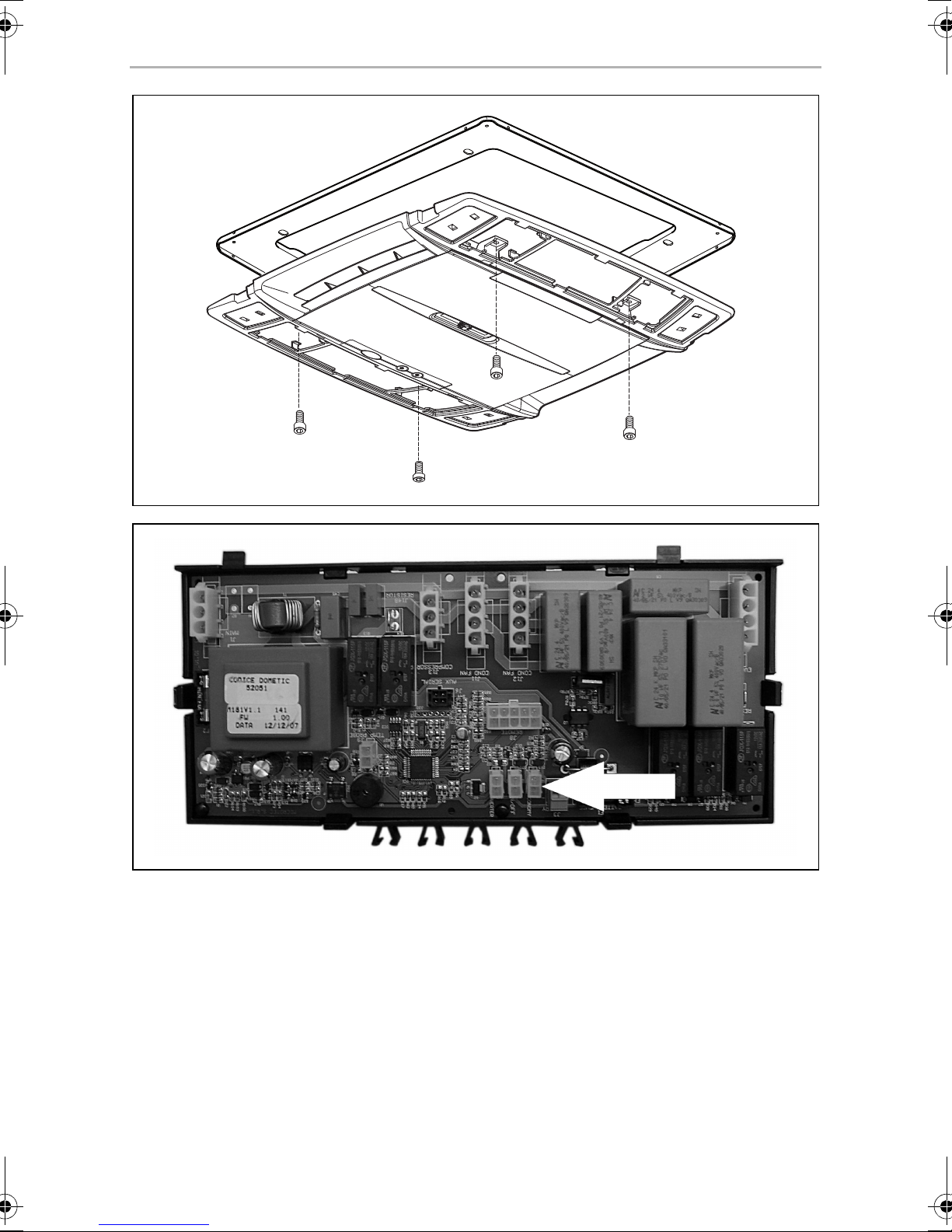
➤ Remove the outlet panel of the roof air conditioner, if necessary also remove the
upper cover ( B2200/B1600 Plus) (fig. 6, page 5).
➤ Join on/off cable for B2200/B1600 Plus to the plug connector on the circuit
board (fig. 7, page 5).
Connect roof air conditioners with a serial number lower than
802200001 in the way described in chapter “Connecting the B1600
and HB2500 Dometic roof air conditioner” on page 19.
NOTE
Guide the on/off cable carefully past the fan.
I
➤ Join the universal connection cable to the on/off cable of the B2200/
B1600Plus.
➤ Connect the universal connection cable with connections I2 and I5 of the
charging current distributor ( ECL-103) (fig. 3, page 4).
➤ Attach the outlet panel of the roof air conditioner ( B2200/B1600 Plus)
(fig. 6, page 5).
➤ Run the connection cable of remote control MCR-9 to the inverter and connect
( MSI1824T).
17
Page 18

EN
Installing and connecting the DC kit DC-Kit5
7.6 Connecting the FJ1100, FJ1700, FJ2200 Dometic roof
air conditioner
➤ Remove the outlet panel of the roof air conditioner, if necessary also remove the
upper cover ( FJ1100, FJ1700, FJ2200) (fig. 8, page 6).
➤ Join on/off cable for FJ1100, FJ1700, FJ2200 to the plug connector on the circuit
board (fig. 9, page 6).
NOTE
Guide the on/off cable carefully past the fan.
I
➤ Join the universal connection cable to the on/off cable of the FJ1100, FJ1700,
FJ2200.
➤ Connect the universal connection cable with connections I2 and I5 of the
charging current distributor ( ECL-103) (fig. 3 1 and 2, page 4).
➤ Attach the outlet panel of the roof air conditioner ( FJ1100, FJ1700, FJ2200)
(fig. 8, page 6).
➤ Run the connection cable of remote control MCR-9 to the inverter and connect
( MSI1824T).
7.7 Connecting the FL1600, FL2200 Dometic roof air
conditioner
➤ Remove the outlet panel of the roof air conditioner, if necessary also remove the
upper cover ( FL1600, FL2200) (fig. 0, page 7).
➤ Join on/off cable for FL1600, FL2200 to the plug connector on the circuit board
(fig. a, page 8).
NOTE
Guide the on/off cable carefully past the fan.
I
➤ Join the universal connection cable to the on/off cable of the FL1600, FL2200.
➤ Connect the universal connection cable with connections I2 and I5 of the
charging current distributor ( ECL-103) (fig. 3 1 and 2, page 4).
➤ Attach the outlet panel of the roof air conditioner ( FL1600, FL2200) (fig. 0,
page 7).
➤ Run the connection cable of remote control MCR-9 to the inverter and connect
( MSI1824T).
18
Page 19

EN
DC-Kit5 Installing and connecting the DC kit
7.8 Connecting the DometicFW3000 storage
compartment air conditioner
➤ Connect the on/off cable for FW3000 to the connection socket on the
connector panel (fig. b, page 8).
NOTE
Guide the on/off cable carefully past the fan.
I
➤ Join the universal connection cable to the on/off cable of the FW3000.
➤ Connect the universal connection cable with connections I2 and I5 of the
charging current distributor ( ECL-103) (fig. 3 1 and 2, page 4).
➤ Run the connection cable of remote control MCR-9 to the inverter and connect
( MSI1824T).
7.9 Connecting the B1600 and HB2500 Dometic roof air
conditioner
➤ Connect the D+-output on the light system using a 1,5 mm² cable to connection
I2 of the changing current distributor ( ECL-103) (fig. 3 1, page 4).
➤ Connect the I5-output of the ECL-103 to the control cable connection on the
MCR-9 remote control (fig. c 1, page 8).
19
Page 20

EN
Using the DC kit DC-Kit5
7.10 Connecting the DC kit to the power supply
➤ Check that all the connections have been made in accordance with the
instructions.
➤ Check that the roof air conditioner is closed properly.
➤ Connect the electrical connections of the components ( ECL-103).
➤ Connect the 230 V connection on the roof air conditioner with the MSI1824T
inverter plug ( MSI1824T).
➤ Connect the positive battery cables to the batteries.
➤ Check the following are working properly:
– Check the on and off values for the charging voltage regulator
– Check the priority circuit
– Switch on the air conditioning in driving mode ( air conditioning)
– Switch on the air conditioning on mains operation
➤ Only CA1000: adapt the roof air conditioner software to AC/DC operation
( CA1000).
8 Using the DC kit
The DC-Kit5 consists of several components, each with its own installation and
operating manual. Use the installation and operating manuals for the components
and make sure you are familiar with the individual devices.
This chapter contains information on operating the overall system. This operating
manual does not replace any information contained in the installation and operating
instructions for the components.
NOTICE!
A
CA2500, B2200, B1600 Plus, HB2500, FJ1100, FJ1700,
FJ2200, FL1600, FL2200, FW3000: the inverter may be damaged.
Ensure that these models are not used in the automatic air conditioning
mode or heating modes for driving. The inverter is not designed for generating this amount of power.
20
Page 21

EN
DC-Kit5 Using the DC kit
NOTICE!
A
CA2500, B2200, B1600 Plus, HB2500, FJ1100, FJ1700,
FJ2200, FL1600, FL2200, FW3000: the inverter may be damaged.
If you are operating the system on the 230 V mains and the automatic air
conditioner or the heating is on, make sure that the inverter is switched
off and stays switched off.
The inverter is not designed for the amount of power an active heating
system requires. If the 230 V mains power fails, the inverter would then
take over supplying the power.
8.1 Switching on the system
Observe the following instructions before you switch on the system:
• Air the vehicle.
• Make sure that the ventilation slots on the air nozzles and the fan of the
components are not covered up.
• Make sure that all the housings and cables are not damaged and that all the
insulation is intact.
• Compare the existing supply voltage with the technical data.
• Do not insert any fingers or objects into component openings.
NOTE
I
Stationary mode: 230 Vw mains operation
The system is supplied with 230 Vw from the mains. Leave the inverter switched off.
Driving mode: power supply from the 24 V battery
➤ Switch on the inverter using the MCR-9 remote control.
CA2500, B2200, B1600 Plus, HB2500, FJ1100, FJ1700,
FJ2200, FL1600, FL2200, FW3000: The remote control for the air
conditioner can only be used if the air conditioner is supplied with 230 V
mains network or with the inverter.
NOTICE!
A
➤ Use the roof air conditioner as described in the operating manual.
CA2500, B2200, B1600 Plus, HB2500, FJ1100, FJ1700,
FJ2200, FL1600, FL2200, FW3000: the inverter may be damaged.
Do not switch on the roof air conditioner in the automatic or heating
modes.
21
Page 22

EN
Using the DC kit DC-Kit5
Driving mode: power supply from the 24 V battery with motor
switched off
• CA1000, CA2500, B2200, B1600 Plus, FJ1100, FJ1700, FJ2200,
FL1600, FL2200, FW3000
If the inverter switches off due to low voltage in the supply battery (21 V), no
voltage will be supplied to the socket and the roof air conditioner switches off.
The inverter is in standby mode.
As soon as the power from the supply battery reaches the inverter's activation
point, the socket is supplied with voltage again.
You have to switch on the roof air conditioner again manually, as the control
electronics need to be reactivated after a lack of voltage.
• B1600, HB2500
If the inverter switches off due to low voltage in the supply battery (21 V), no
voltage will be supplied to the socket and the air conditioner switches off. The
inverter is in standby mode.
As soon as the power from the supply battery reaches the inverter's activation
point, the socket is supplied with voltage again.
The air conditioner starts automatically.
Driving mode: power supply from the 24 V battery with motor
switched on
In driving mode, the starter and supply battery are electrically connected when the
light system is active. This means the supply battery can be charged from the light
system.
Starter batteries may not be discharged as much as supply batteries. To preserve the
starter battery, the charging current distributor separates the starter battery from the
supply battery, if the charging voltage in the starter battery drops below 21 V. This
also ensures that the starter battery is charged before the supply battery.
• CA1000, CA2500
If the charging voltage regulator cuts the connection to the supply battery due
to low voltage, it switches off the compressor in the roof air conditioner at the
same time. The inverter remains active and has voltage in its socket.
As soon as the voltage in supply battery has reached the switch-on point in the
charging current distributor, the compressor in the roof air conditioner switches
on again.
If the voltage in the supply battery drops further and goes below the 21 V switchoff point for the inverter, the inverter switches off (chapter “Driving mode: power
supply from the 24 V battery with motor switched off” on page 22).
22
Page 23

EN
DC-Kit5 Using the DC kit
• B2200, B1600 Plus, FJ1100, FJ1700, FJ2200, FL1600, FL2200,
FW3000
If the charging voltage regulator cuts the connection to the supply battery due
to low voltage, it switches off the roof air conditioner at the same time. The
inverter remains active and has voltage in its socket.
As soon as the voltage in supply battery has reached the switch-on point in the
charging current distributor, the roof air conditioner switches on again.
If the voltage in the supply battery drops further and goes below the 21 V switchoff point for the inverter, the inverter switches off (chapter “Driving mode: power
supply from the 24 V battery with motor switched off” on page 22).
• B1600, HB2500
If the charging voltage regulator cuts the connection to the supply battery due
to low voltage, it switches off the inverter at the same time using the MCR-9
remote control. There is no voltage in the socket for the inverter.
As soon as the voltage in the supply battery reaches the switch-on point in the
charging current distributor, it restores the connection between the starter and
supply battery and switches the inverter on again using the MCR-9 remote
control. There is voltage in the socket again for the inverter.
The air conditioning starts again automatically.
If the voltage in the supply battery drops further and goes below the 21 V switch-
off point for the inverter, the inverter switches off (chapter “Driving mode: power
supply from the 24 V battery with motor switched off” on page 22).
8.2 Switching off the system
➤ First of all, switch off the air conditioning.
➤ If there are no more consumer units which need power, switch off the inverter
using the MCR-9 remote control.
23
Page 24

EN
Maintaining and cleaning the DC kit DC-Kit5
9 Maintaining and cleaning the DC kit
NOTE
I
➤ Check the power supply lines for abrasion or defects regularly.
➤ Have the system checked regularly by a specialist.
➤ If you find any faulty fuses, have the system checked by a specialist.
Observe the maintenance and cleaning instructions in the operating
manuals of the individual components.
10 Rectifying faults
NOTE
I
Observe the instructions on rectifying faults in the operating manuals of
the individual components.
11 Warranty
The statutory warranty period applies. If the product is defective, please contact the
manufacturer's branch in your country (see the back of the instruction manual for the
addresses) or your retailer.
For repair and guarantee processing, please include the following documents when
you send in the device:
• A copy of the receipt with purchasing date
• A reason for the claim or description of the fault
24
Page 25

EN
DC-Kit5 Disposal
12 Disposal
➤ Place the packaging material in the appropriate recycling waste bins wherever
possible.
If you wish to finally dispose of the product, ask your local recycling centre
or specialist dealer for details about how to do this in accordance with the
M
applicable disposal regulations.
13 Technical data
NOTE
I
You can find the technical data for the components in the corresponding
installation and operating manual.
25
Page 26

DE
DC-Kit5
Bitte lesen Sie diese Anleitung vor Einbau und Inbetriebnahme sorgfältig
durch und bewahren Sie sie auf. Geben Sie sie im Falle einer Weitergabe
des Produktes an den Nutzer weiter.
Inhaltsverzeichnis
1 Erklärung der Symbole . . . . . . . . . . . . . . . . . . . . . . . . . . . . . . . . . . . . . . . . . 27
2 Allgemeine Sicherheitshinweise . . . . . . . . . . . . . . . . . . . . . . . . . . . . . . . . . 27
3 Lieferumfang . . . . . . . . . . . . . . . . . . . . . . . . . . . . . . . . . . . . . . . . . . . . . . . . . 30
4 Zielgruppe dieser Anleitung . . . . . . . . . . . . . . . . . . . . . . . . . . . . . . . . . . . . 30
5 Bestimmungsgemäßer Gebrauch . . . . . . . . . . . . . . . . . . . . . . . . . . . . . . . . .31
6 Technische Beschreibung . . . . . . . . . . . . . . . . . . . . . . . . . . . . . . . . . . . . . . 32
7 DC-Kit montieren und anschließen . . . . . . . . . . . . . . . . . . . . . . . . . . . . . . . 33
8 DC-Kit benutzen . . . . . . . . . . . . . . . . . . . . . . . . . . . . . . . . . . . . . . . . . . . . . . 40
9 DC-Kit pflegen und warten. . . . . . . . . . . . . . . . . . . . . . . . . . . . . . . . . . . . . . 44
10 Fehlerbeseitigung. . . . . . . . . . . . . . . . . . . . . . . . . . . . . . . . . . . . . . . . . . . . . 44
11 Gewährleistung. . . . . . . . . . . . . . . . . . . . . . . . . . . . . . . . . . . . . . . . . . . . . . . 44
12 Entsorgung . . . . . . . . . . . . . . . . . . . . . . . . . . . . . . . . . . . . . . . . . . . . . . . . . . 45
13 Technische Daten . . . . . . . . . . . . . . . . . . . . . . . . . . . . . . . . . . . . . . . . . . . . . 45
26
Page 27
DE
DC-Kit5 Erklärung der Symbole
1 Erklärung der Symbole
GEFAHR!
D
!
A
Sicherheitshinweis: Nichtbeachtung führt zu Tod oder schwerer
Verletzung.
WARNUNG!
Sicherheitshinweis: Nichtbeachtung kann zu Tod oder schwerer
Verletzung führen.
ACHTUNG!
Nichtbeachtung kann zu Materialschäden führen und die Funktion des
Produktes beeinträchtigen.
HINWEIS
Ergänzende Informationen zur Bedienung des Produktes.
I
2 Allgemeine Sicherheitshinweise
Der Hersteller übernimmt in folgenden Fällen keine Haftung für Schäden:
• Montage- oder Anschlussfehler
• Beschädigungen am Produkt durch mechanische Einflüsse und Über-
spannungen
• Veränderungen am Produkt ohne ausdrückliche Genehmigung vom Hersteller
• Verwendung für andere als die in der Anleitung beschriebenen Zwecke
27
Page 28
DE
Allgemeine Sicherheitshinweise DC-Kit5
2.1 Allgemeine Sicherheit
WARNUNG!
!
• Beachten Sie auch die Sicherheitshinweise in den Montage- und
Bedienungsanleitung zu den mitgelieferten Komponenten und zu
Ihrer Dometic Klimaanlage.
• Benutzen Sie das Gerät nur zu seinem bestimmungsgemäßen
Gebrauch.
• Personen, die aufgrund ihrer physischen, sensorischen oder geistigen
Fähigkeiten oder ihrer Unerfahrenheit oder Unkenntnis nicht in der
Lage sind, das Gerät sicher zu benutzen, sollten dieses Gerät nicht
ohne Aufsicht oder Anweisung durch eine verantwortliche Person
nutzen.
• Elektrogeräte sind kein Kinderspielzeug!
Verwahren und benutzen Sie das Gerät außerhalb der Reichweite von
Kindern.
• Kinder sollten beaufsichtigt werden, um sicherzustellen, dass sie nicht
mit dem Gerät spielen.
• Die Wartung und Reparatur darf nur durch eine Fachkraft geschehen,
die mit den damit verbundenen Gefahren bzw. einschlägigen Vorschriften vertraut ist.
2.2 Sicherheit bei der Installation und Reparatur
WARNUNG!
!
• Die Installation und Reparatur des Gerätes darf ausschließlich von
entsprechend ausgebildeten Fachbetrieben durchgeführt werden,
die mit den Gefahren sowie den anzuwendenen Richtlinien und
Sicherheitsvorkehrungen vertraut sind.
28
Page 29

DE
DC-Kit5 Allgemeine Sicherheitshinweise
2.3 Sicherheit beim Betrieb
WARNUNG!
!
Beachten Sie folgende grundsätzliche Sicherheitsmaßnahmen beim
Gebrauch von elektrischen Geräten zum Schutz vor:
• elektrischem Schlag
• Brandgefahr
• Verletzungen
• Betreiben Sie das System nur, wenn alle Gehäuse und Leitungen
unbeschädigt sind.
• Die 24-V-Anschlusskabel sind für hohe Ströme ausgelegt.
Modifizieren Sie die Kabel nicht. Falls nötig, lassen Sie das nur durch
einen Fachmann durchführen.
• Achten Sie darauf, dass Luftein- und Ausgänge des Geräts nicht verdeckt werden.
• Achten Sie auf gute Belüftung. Der Wechselrichter produziert Verlustwärme, die abgeführt werden muss.
• Unterbrechen Sie bei Arbeiten am Gerät immer die Stromversorgung.
29
Page 30

DE
Lieferumfang DC-Kit5
3 Lieferumfang
Menge Bezeichnung Artikelnummer
1 Ladestromverteiler ECL-103 9600000548
1 Wechselrichter MSI1824T mit Vorrangschaltung 9600000011
1 Fernbedienung für den Wechselrichter MCR-9
(einschließlich Anschlusskabel)
1 2-adrige Steuerleitung für MCR-9
(CA2500, B1600, HB2500)
1 2-adrige Steuerleitung für
B2200/B1600 Plus
1 Sensing Cable für CA1000 4441300084
1Anschlusskabel
schwarze Zuleitung (35 mm², 1,5 m lang)
rote Zuleitung (35 mm², 1,5 m lang)
1 Sensing Cable für FreshJet/FreshLight/FreshWell 4441300221
1 Montage- und Bedienungsanleitung 4445101956
9600000091
4441300124
4441300129
4441300120
4441300119
Prüfen Sie vor Inbetriebnahme des Systems, ob alle zum Lieferumfang gehörenden
Teile vorhanden und verbaut sind.
4 Zielgruppe dieser Anleitung
Die Einbauinformationen in dieser Anleitung wenden sich ausschließlich an Fachleute in Werkstätten, die mit den anzuwendenden Richtlinien und Sicherheitsvorkehrungen beim Einbau von Fahrzeugzubehörteilen vertraut sind.
Alle übrigen Kapitel wenden sich auch an die Benutzer des Gerätes.
30
Page 31

DE
DC-Kit5 Bestimmungsgemäßer Gebrauch
5 Bestimmungsgemäßer Gebrauch
Das Erweiterungskit DC-Kit5 (Art.-Nr. 9100300073) ist geeignet, um die folgenden
Dometic Dachklimaanlagen für den 24-Vg-Fahrbetrieb aufzurüsten:
• CA1000, CA2500
• B1600, B2200, B1600 Plus, HB2500
• FJ1100, FJ1700, FJ2200
• FL1600, FL2200
• FW3000
Der Wechselrichter MSI1824T ist nur für den Kühleinsatz der Dachklimaanlage ausgelegt, nicht für den Heizbetrieb, da die Heizelemente mehr Strom aufnehmen als
der Wechselrichter im Dauerbetrieb erzeugen kann.
HINWEIS
I
Die in dieser Anleitung beschriebenen Funktionen zur Dometic Dachklimaanlage B2200 gelten für Dachklimaanlagen mit einer Seriennummer über 802200001.
Für Dometic Dachklimaanlagen B2200 mit einer niedrigeren Seriennummer gelten die Angaben zur Dometic Dachklimaanlage B1600.
31
Page 32

DE
Technische Beschreibung DC-Kit5
6 Technische Beschreibung
Das Erweiterungskit DC-Kit5 ermöglicht es, Dometic Dachklimaanlagen in Fahrzeugen mit 24 Vg zu betreiben. Das Erweiterungskit besteht aus den folgenden
Komponenten:
• Der Ladestromverteiler ECL-103 mit Unterspannungsschutz regelt die Strom-
verteilung zwischen Starterbatterie, Versorgungsbatterie und Lichtmaschine. Er
verhindert so eine Überlastung der Batterien und der Bordelektronik.
• Der Wechselrichter MSI1824T versorgt die Dachklimaanlage mit der erforder-
lichen Eingangsspannung von 230 Vw. Der Wechselrichter generiert diese
230-V-Eingangsspannung aus der 24-V-Bordnetzspannung des Fahrzeugs.
Die integrierte Vorrangschaltung dient zur Spannungsverteilung in Fahrzeugen
mit zwei möglichen Stromquellen. Wenn am Gerät eine Festnetz-Spannung und
eine von einem Wechselrichter erzeugte Spannung (Fahrzeugbatterie) anliegt,
wird vorrangig die Festnetz-Spannung genutzt. Nur wenn ausschließlich die
vom Wechselrichter erzeugte Spannung zur Verfügung steht, wird die Stromversorgung durch die Batterie gewählt. So wird sichergestellt, dass die
begrenzte Energie der Batterie nicht unnötig verbraucht wird.
• Durch die Fernbedienung MCR-9 kann der Wechselrichter ein- und ausge-
schaltet werden.
32
Page 33

DE
DC-Kit5 DC-Kit montieren und anschließen
7 DC-Kit montieren und anschließen
ACHTUNG!
A
A
Der Einbau des DC-Kits darf ausschließlich von entsprechend ausgebildeten Fachbetrieben durchgeführt werden.
Die nachfolgenden Informationen richten sich an Fachkräfte die mit den
anzuwendenen Richtlinien und Sicherheitsvorkehrungen vertraut sind.
ACHTUNG!
Beachten Sie beim Einbau auch die Informationen in den Montage- und
Bedienungsanleitung zu den mitgelieferten Komponenten
• Wechselrichter MSI1824T
• Fernbedienung MCR-9
• Ladestromverteiler ECL-103
und zu Ihrer Dometic Dachklimaanlage
• CA1000, CA2500
• B1600, B1600 Plus, B2200
• HB2500
• FJ1100, FJ1700, FJ2200
• FL1600, FL2200
• FW3000
Beachten Sie folgende Sicherheitshinweise bei der Montage:
ACHTUNG!
A
• Achten Sie beim Einbau der Komponenten auf den Verlauf von
Kabelsträngen, Leitungen und anderen Komponenten, die sich im
Montagebereich befinden.
• Installieren Sie das DC-Kit entsprechend den folgenden Handlungsanweisungen. Eine falsche Installation des DC-Kits kann die Sicherheit des Benutzers beeinträchtigen und zu irreparablen Schäden am
DC-Kit oder anderen Geräten führen.
• Unterbrechen Sie alle Stromversorgungen zu den einzelnen
Komponenten und zur Dachklimaanlage.
33
Page 34

DE
DC-Kit montieren und anschließen DC-Kit5
Beachten Sie folgende Sicherheitshinweise beim elektrischen Anschluss:
ACHTUNG! Kurzschlussgefahr!
A
• Trennen Sie zuerst die 230-V-Fremdversorgung zum Wohnmobil.
• Trennen Sie die Masse-Verbindung zur Versorgungsbatterie.
• Trennen Sie die Verbindung zur Starterbatterie.
• Wenn Sie Leitungen durch Blechwände oder andere scharfkantige
Wände führen müssen, benutzen Sie Leerrohre oder Leitungsdurchführungen.
• Verlegen Sie Leitungen nicht lose oder scharf abgeknickt an
elektrisch leitenden Materialien (Metall).
• Befestigen Sie die Leitungen gut.
• Verlegen Sie die 24-V-Leitungen besonders geschützt.
• Prüfen sie, ob Sie zusätzliche Schmelzsicherungen einsetzen
müssen.
• Ziehen Sie nicht an Leitungen.
• Verlegen Sie 230-V-Netzleitung und 12/24-V-Gleichstromleitung
nicht zusammen im gleichen Leitungskanal (Leerrohr).
• Verlegen Sie die Leitungen so, dass keine Stolpergefahr entsteht
und eine Beschädigung des Kabels ausgeschlossen ist.
Beachten Sie folgende Hinweise bei der Wahl der Montageorte für die
Komponenten:
• Beachten Sie die Kabellängen.
• Wählen Sie einen gut belüfteten Montageort nahe der Versorgungsbatterie.
7.1 Einbau vorbereiten
➤ Folgende Spannungsversorgungen des Fahrzeuges lösen:
– Pluspol der Batterie
– Externe Spannungsversorgung
34
Page 35

DE
DC-Kit5 DC-Kit montieren und anschließen
7.2 Komponenten montieren
➤ Ladestromverteiler ECL-103 montieren.
➤ Wechselrichter MSI1824T montieren.
➤ Fernbedienung MCR-9 montieren.
GEFAHR! Stromschlag!
D
Schließen Sie die Batterieanschlüsse erst dann an, wenn die gesamte
Installation abgeschlossen ist und Sie sich von der fehlerfreien Installation überzeugt haben.
7.3 Dometic Dachklimaanlage CA1000 anschließen
➤ Luftauslasseinheit der Dachklimaanlage entfernen ( CA1000) (Abb. 1,
Seite 3).
➤ Ein-/Ausschaltkabel für CA1000 in die Buchse auf der Steuerplatine der Dach-
klimaanlage stecken (Abb. 2 1, Seite 3).
➤ Ein-/Ausschaltkabel von der Dachklimaanlage zum Ladestromverteiler ECL-103
verlegen.
➤ Ein-/Ausschaltkabel mit den Anschlüssen I2 und I3 des Ladestromverteilers ver-
binden ( ECL-103) (Abb. 3, Seite 4).
➤ Luftauslasseinheit der Dachklimaanlage befestigen ( CA1000) (Abb. 1,
Seite 3).
➤ Verbindungskabel der Fernbedienung MCR-9 zum Wechselrichter verlegen und
anschließen ( MSI1824T).
7.4 Dometic Dachklimaanlage CA2500 anschließen
➤ Luftauslasseinheit der Dachklimaanlage entfernen ( CA2500) (Abb. 4,
Seite 4).
➤ Kabelschlaufe des Ein-/Ausschaltkabels von CA2500 mittig durchtrennen
(Abb. 5 A, Seite 4).
➤ Steuerleitung an das Ein-/Ausschaltkabel anschließen (Abb. 5 B, Seite 4).
➤ Steuerleitung von der Dachklimaanlage zum Ladestromverteiler ECL-103
verlegen.
➤ Steuerleitung mit den Anschlüssen I2 und I3 des Ladestromverteilers verbinden
( ECL-103) (Abb. 3, Seite 4).
35
Page 36

DE
DC-Kit montieren und anschließen DC-Kit5
➤ Luftauslasseinheit der Dachklimaanlage befestigen ( CA2500) (Abb. 4,
Seite 4).
➤ Verbindungskabel der Fernbedienung MCR-9 zum Wechselrichter verlegen und
anschließen ( MSI1824T).
7.5 Dometic Dachklimaanlage B2200/B1600 Plus
anschließen
HINWEIS
I
➤ Auslasspanel der Dachklimaanlage entfernen, ggf. die obere Abdeckhaube ent-
fernen ( B2200/B1600 Plus) (Abb. 6, Seite 5).
Schließen Sie Dachklimaanlagen mit einer Seriennummer unter
802200001 so an wie in Kapitel „Dometic Klimaanlage B1600 und
HB2500 anschließen“ auf Seite 39 beschrieben.
➤ Ein-/Ausschaltkabel für B2200/B1600 Plus mit dem Steckanschluss auf der
Platine (Abb. 7, Seite 5) verbinden.
HINWEIS
Führen Sie das Ein-/Ausschaltkabel vorsichtig am Lüfter vorbei.
I
➤ Universalverbindungskabel mit dem Ein-/Ausschaltkabel der B2200/
B1600 Plus verbinden.
➤ Universalverbindungskabel mit den Anschlüssen I2 und I5 des Ladestrom-
verteilers verbinden ( ECL-103) (Abb. 3, Seite 4).
➤ Auslasspanel der Dachklimaanlage befestigen ( B2200/B1600 Plus)
(Abb. 6, Seite 5).
➤ Verbindungskabel der Fernbedienung MCR-9 zum Wechselrichter verlegen und
anschließen ( MSI1824T).
36
Page 37

DE
DC-Kit5 DC-Kit montieren und anschließen
7.6 Dometic Dachklimaanlage FJ1100, FJ1700, FJ2200
anschließen
➤ Auslasspanel der Dachklimaanlage entfernen, ggf. die obere Abdeckhaube ent-
fernen ( FJ1100, FJ1700, FJ2200) (Abb. 8, Seite 6).
➤ Ein-/Ausschaltkabel für FJ1100, FJ1700, FJ2200 mit dem Steckanschluss auf der
Platine verbinden (Abb. 9, Seite 6).
HINWEIS
Führen Sie das Ein-/Ausschaltkabel vorsichtig am Lüfter vorbei.
I
➤ Universalverbindungskabel mit dem Ein-/Ausschaltkabel der FJ1100, FJ1700,
FJ2200 verbinden.
➤ Universalverbindungskabel mit den Anschlüssen I2 und I5 des Ladestrom-
verteilers verbinden ( ECL-103) (Abb. 3, Seite 4).
➤ Auslasspanel der Dachklimaanlage befestigen ( FJ1100, FJ1700, FJ2200)
(Abb. 8, Seite 6).
➤ Verbindungskabel der Fernbedienung MCR-9 zum Wechselrichter verlegen und
anschließen ( MSI1824T).
37
Page 38

DE
DC-Kit montieren und anschließen DC-Kit5
7.7 Dometic Dachklimaanlage FL1600, FL2200
anschließen
➤ Auslasspanel der Dachklimaanlage entfernen, ggf. die obere Abdeckhaube ent-
fernen ( FL1600, FL2200) (Abb. 0, Seite 7).
➤ Ein-/Ausschaltkabel für FL1600, FL2200 mit dem Steckanschluss auf der Platine
verbinden (Abb. a, Seite 8).
HINWEIS
Führen Sie das Ein-/Ausschaltkabel vorsichtig am Lüfter vorbei.
I
➤ Universalverbindungskabel mit dem Ein-/Ausschaltkabel der FL1600, FL2200
verbinden
➤ Universalverbindungskabel mit den Anschlüssen I2 und I5 des Ladestrom-
verteilers verbinden ( ECL-103) (Abb. 3, Seite 4).
➤ Auslasspanel der Dachklimaanlage befestigen ( FL1600, FL2200) (Abb. 0,
Seite 7).
➤ Verbindungskabel der Fernbedienung MCR-9 zum Wechselrichter verlegen und
anschließen ( MSI1824T).
7.8 Dometic Staukastenklimaanlage FW3000
anschließen
➤ Ein-/Ausschaltkabel für FW3000 mit dem Steckanschluss am Anschlussfeld ver-
binden (Abb. b, Seite 8).
HINWEIS
Führen Sie das Ein-/Ausschaltkabel vorsichtig am Lüfter vorbei.
I
➤ Universalverbindungskabel mit dem Ein-/Ausschaltkabel der FW3000
verbinden.
➤ Universalverbindungskabel mit den Anschlüssen I2 und I5 des Ladestrom-
verteilers verbinden ( ECL-103) (Abb. 3, Seite 4).
➤ Verbindungskabel der Fernbedienung MCR-9 zum Wechselrichter verlegen und
anschließen ( MSI1824T).
38
Page 39

DE
DC-Kit5 DC-Kit montieren und anschließen
7.9 Dometic Klimaanlage B1600 und HB2500
anschließen
➤ D+-Ausgang der Lichtmaschine mit einem 1-mm²-Kabel mit dem Anschluss I2
des Ladestromverteilers verbinden ( ECL-103) (Abb. 3, Seite 4).
➤ I5-Ausgang des ECL-103 mit dem Steuerleitungsanschluss der Fernbedienung
MCR-9 verbinden (Abb. c 1, Seite 8).
7.10 DC-Kit elektrisch anschließen
➤ Prüfen, ob alle Anschlüsse gemäß den Anweisungen und Vorschriften ange-
schlossen sind.
➤ Prüfen, ob die Dachklimaanlage ordnungsgemäß verschlossen ist.
➤ Elektrische Verbindungen der Komponenten anschließen ( ECL-103).
➤ 230-V-Anschluss der Dachklimaanlage mit der Stecker des Wechselrichters
MSI1824T verbinden ( MSI1824T).
➤ Pluskabel der Batterieleitungen an die Batterien anschließen.
➤ Installation auf korrekte Funktion prüfen:
– Ein- und Ausschaltwerte des Ladespannungsreglers prüfen
– Funktion der Vorrangschaltung prüfen
– Im Fahrbetrieb die Klimaanlage einschalten ( Dachklimaanlage)
– Im Netzbetrieb die Klimaanlage einschalten
➤ Nur CA1000: Software der Dachklimaanlage auf den AC/DC-Betrieb anpassen
( CA1000).
39
Page 40

DE
DC-Kit benutzen DC-Kit5
8 DC-Kit benutzen
Das DC-Kit5 besteht aus mehreren Komponenten, die jeweils eigene Montage- und
Bedienungsanleitungen haben. Bitte nutzen Sie die Montage- und Bedienungsanleitungen der Komponenten und machen Sie sich mit den einzelnen Geräten
vertraut.
In diesem Kapitel finden Sie Hinweise zur Bedienung des Gesamtsystems. Diese
Bedienungsanleitung ersetzt nicht die Informationen in den Montage- und
Bedienungsanleitungen der Komponenten.
ACHTUNG!
A
CA2500, B2200, B1600 Plus, HB2500, FJ1100, FJ1700,
FJ2200, FL1600, FL2200, FW3000: Der Wechselrichter kann
beschädigt werden.
Stellen Sie für den Betrieb im Fahrbetriebmodus sicher, dass die
Anlagen nicht im Klimaautomatikbetrieb oder Heizbetrieb betrieben
werden. Der Wechselrichter ist nicht dafür ausgelegt, die benötigte
Leistung zu erzeugen.
A
ACHTUNG!
CA2500, B2200, B1600 Plus, HB2500, FJ1100, FJ1700,
FJ2200, FL1600, FL2200, FW3000: Der Wechselrichter kann
beschädigt werden.
Falls Sie die Anlage am 230-V-Netz betreiben und die Klimaautomatik
oder den Heizbetrieb aktiviert haben, achten Sie darauf, dass der
Wechselrichter ausgeschaltet ist und bleibt.
Der Wechselrichter ist nicht für die Leistungen ausgelegt, die eine
aktivierte Heizung benötigt. Bei Ausfall des 230-V-Netzes würde sonst
der Wechselrichter die Stromversorgung übernehmen.
40
Page 41

DE
DC-Kit5 DC-Kit benutzen
8.1 Anlage einschalten
Beachten Sie folgende Hinweise, bevor Sie das System einschalten:
• Lüften Sie das Fahrzeug.
• Stellen Sie sicher, dass die Lüftungsöffnungen der Luftdüsen und Lüfter der
Komponenten nicht verdeckt sind.
• Stellen Sie sicher, dass alle Gehäuse und Kabel unbeschädigt sind und dass alle
Isolierungen intakt sind.
• Vergleichen Sie die vorhandene Versorgungsspannung mit den technischen
Daten.
• Stecken Sie keine Finger oder Gegenstände in Öffnungen von Komponenten.
HINWEIS
I
CA2500, B2200, B1600 Plus, HB2500, FJ1100, FJ1700,
FJ2200, FL1600, FL2200, FW3000: Die Fernbedienung der Klima-
anlage kann nur genutzt werden, wenn die Klimaanlage entweder vom
230-V-Netz oder vom Wechselrichter mit Spannung versorgt wird.
Standbetrieb: 230-Vw-Netzbetrieb
Das System wird vom 230-Vw-Netz versorgt. Lassen Sie den Wechselrichter ausgeschaltet.
Fahrbetrieb: Versorgung durch die 24-V-Batterie
➤ Schalten Sie den Wechselrichter über die Fernbedienung MCR-9 ein.
ACHTUNG!
A
➤ Verwenden Sie die Dachklimaanlage wie in deren Bedienungsanleitung
beschrieben.
CA2500, B2200, B1600 Plus, HB2500, FJ1100, FJ1700,
FJ2200, FL1600, FL2200, FW3000: Der Wechselrichter kann
beschädigt werden.
Schalten Sie die Dachklimaanlage nicht in den Automatik- oder
Heizbetrieb.
41
Page 42

DE
DC-Kit benutzen DC-Kit5
Fahrbetrieb: Versorgung durch die 24-V-Batterie bei ausgeschaltetem
Motor
• CA1000, CA2500, B2200, B1600 Plus, FJ1100, FJ1700, FJ2200,
FL1600, FL2200, FW3000
Wenn der Wechselrichter wegen Unterspannung der Versorgerbatterie (21 V)
abschaltet, liegt an seiner Steckdose keine Spannung mehr an und die Dachklimaanlage schaltet ab. Der Wechselrichter bleibt in Bereitschaft.
Sobald die Spannung der Versorgerbatterie den Einschaltwert des Wechselrichters erreicht, liegt an seiner Steckdose wieder Spannung an.
Sie müssen die Dachklimaanlage manuell wieder einschalten, weil die
Steuerungselektronik der Dachklimaanlage nach Spannungslosigkeit wieder
aktiviert werden muss.
• B1600, HB2500
Wenn der Wechselrichter wegen Unterspannung der Versorgerbatterie (21 V)
abschaltet, liegt an seiner Steckdose keine Spannung mehr an und die Klimaanlage schaltet ab. Der Wechselrichter bleibt in Bereitschaft.
Sobald die Spannung der Versorgerbatterie den Einschaltwert des Wechselrichters erreicht, liegt an seiner Steckdose wieder Spannung an.
Die Klimaanlage startet automatisch.
Fahrbetrieb: Versorgung durch die 24-V-Batterie bei gestartetem Motor
Im Fahrbetrieb sind bei aktiver Lichtmaschine die Starter- und Versorgerbatterie
elektrisch verbunden. Dadurch kann die Versorgerbatterie von der der Lichtmaschine geladen werden.
Starterbatterien dürfen nicht so tief entladen werden wie Versorgerbatterien. Zum
Schutz der Starterbatterie, trennt der Ladestromverteiler deshalb die Starterbatterie
von der Versorgerbatterie, wenn die Ladespannung der Starterbatterie unter 21 V
sinkt. Außerdem wird so sichergestellt, dass die Starterbatterie vor der Versorgerbatterie geladen wird.
42
Page 43

DE
DC-Kit5 DC-Kit benutzen
• CA1000, CA2500
Wenn der Ladespannungsregler wegen Unterspannung die Verbindung zur
Versorgerbatterie trennt, schaltet er gleichzeitig den Kompressor der Dachklimaanlage ab. Der Wechselrichter bleibt weiterhin aktiv und an seiner Steckdose liegt Spannung an.
Sobald die Spannung der Versorgerbatterie den Einschaltwert des Ladestromverteilers erreicht, wird der Kompressor der Dachklimaanlage wieder eingeschaltet.
Falls die Spannung der Versorgerbatterie weiter fällt und unter den Ausschaltwert des 21 V des Wechselrichters sinkt, wird der Wechselrichter abgeschaltet
(Kapitel „Fahrbetrieb: Versorgung durch die 24-V-Batterie bei ausgeschaltetem
Motor“ auf Seite 42).
• B2200, B1600 Plus, FJ1100, FJ1700, FJ2200, FL1600, FL2200,
FW3000
Wenn der Ladespannungsregler wegen Unterspannung die Verbindung zur
Versorgerbatterie trennt, schaltet er gleichzeitig die Dachklimaanlage ab. Der
Wechselrichter bleibt weiterhin aktiv und an seiner Steckdose liegt Spannung
an.
Sobald die Spannung der Versorgerbatterie den Einschaltwert des Ladestromverteilers erreicht, wird die Dachklimaanlage wieder eingeschaltet.
Falls die Spannung der Versorgerbatterie weiter fällt und unter den Ausschaltwert des 21 V des Wechselrichters sinkt, wird der Wechselrichter abgeschaltet
(Kapitel „Fahrbetrieb: Versorgung durch die 24-V-Batterie bei ausgeschaltetem
Motor“ auf Seite 42).
• B1600, HB2500
Wenn der Ladespannungsregler wegen Unterspannung die Verbindung zur
Versorgerbatterie trennt, schaltet er gleichzeitig über die Fernbedienung MCR-9
den Wechselrichter aus. An der Steckdose des Wechselrichters liegt keine
Spannung mehr an.
Sobald die Spannung der Versorgerbatterie den Einschaltwert des Ladestromverteilers erreicht, stellt der Ladestromverteiler die Verbindung zwischen Starterund Versorgerbatterie wieder her und schaltet über die Fernbedienung MCR-9
den Wechselrichter wieder ein. An der Steckdose des Wechselrichters liegt
wieder Spannung an.
Die Klimaanlage startet automatisch wieder.
Falls die Spannung der Versorgerbatterie weiter fällt und unter den Ausschalt-
wert des 21 V des Wechselrichters sinkt, wird der Wechselrichter abgeschaltet
(Kapitel „Fahrbetrieb: Versorgung durch die 24-V-Batterie bei ausgeschaltetem
Motor“ auf Seite 42).
43
Page 44

DE
DC-Kit pflegen und warten DC-Kit5
8.2 Anlage ausschalten
➤ Schalten Sie zuerst die Klimaanlage aus.
➤ Wenn Sie keine weiteren Verbraucher mit Strom versorgen, schalten Sie den
Wechselrichter über die Fernbedienung MCR-9 aus.
9 DC-Kit pflegen und warten
HINWEIS
I
➤ Prüfen Sie in regelmäßigen Abständen die Stromleitungen auf Scheuerstellen
oder Defekte.
➤ Lassen Sie die Anlage in regelmäßigen Abständen von einem Fachmann
kontrollieren.
Beachten Sie die Pflege- und Reinigungsanweisungen in den
Bedienungsanleitungen der einzelnen Komponenten.
➤ Wenn Sie defekte Schmelzsicherungen finden, lassen Sie die Anlage von einem
Fachmann kontrollieren.
10 Fehlerbeseitigung
HINWEIS
I
Beachten Sie die Hinweise zur Fehlerbeseitigung in den Bedienungsanleitungen der einzelnen Komponenten.
11 Gewährleistung
Es gilt die gesetzliche Gewährleistungsfrist. Sollte das Produkt defekt sein, wenden
Sie sich bitte an die Niederlassung des Herstellers in Ihrem Land (Adressen siehe
Rückseite der Anleitung) oder an Ihren Fachhändler.
Zur Reparatur- bzw. Gewährleistungsbearbeitung müssen Sie folgende Unterlagen
mitschicken:
• eine Kopie der Rechnung mit Kaufdatum,
• einen Reklamationsgrund oder eine Fehlerbeschreibung.
44
Page 45

DE
DC-Kit5 Entsorgung
12 Entsorgung
➤ Geben Sie das Verpackungsmaterial möglichst in den entsprechenden
Recycling-Müll.
Wenn Sie das Produkt endgültig außer Betrieb nehmen, informieren Sie
sich bitte beim nächsten Recyclingcenter oder bei Ihrem Fachhändler
M
über die zutreffenden Entsorgungsvorschriften.
13 Technische Daten
HINWEIS
I
Die technischen Daten der Komponenten finden Sie in den
zugehörigen Montage- und Bedienungsanleitungen.
45
Page 46

FR
DC-Kit5
Veuillez lire attentivement cette notice avant le montage et la mise en
service. Veuillez ensuite la conserver. En cas de passer le produit, veuillez
le transmettre au nouvel acquéreur.
Table des matières
1 Explication des symboles . . . . . . . . . . . . . . . . . . . . . . . . . . . . . . . . . . . . . . . 47
2 Consignes de sécurité générales . . . . . . . . . . . . . . . . . . . . . . . . . . . . . . . . . 47
3 Contenu de la livraison . . . . . . . . . . . . . . . . . . . . . . . . . . . . . . . . . . . . . . . . . 49
4 Groupe cible de cette notice . . . . . . . . . . . . . . . . . . . . . . . . . . . . . . . . . . . . 49
5 Usage conforme . . . . . . . . . . . . . . . . . . . . . . . . . . . . . . . . . . . . . . . . . . . . . . 50
6 Description technique . . . . . . . . . . . . . . . . . . . . . . . . . . . . . . . . . . . . . . . . . .51
7 Montage et raccordement du kit CC. . . . . . . . . . . . . . . . . . . . . . . . . . . . . . 52
8 Utilisation du kit CC. . . . . . . . . . . . . . . . . . . . . . . . . . . . . . . . . . . . . . . . . . . . 58
9 Entretien et maintenance du kit CC . . . . . . . . . . . . . . . . . . . . . . . . . . . . . . . 62
10 Réparation des pannes . . . . . . . . . . . . . . . . . . . . . . . . . . . . . . . . . . . . . . . . . 63
11 Garantie. . . . . . . . . . . . . . . . . . . . . . . . . . . . . . . . . . . . . . . . . . . . . . . . . . . . . 63
12 Recyclage . . . . . . . . . . . . . . . . . . . . . . . . . . . . . . . . . . . . . . . . . . . . . . . . . . . 63
13 Caractéristiques techniques . . . . . . . . . . . . . . . . . . . . . . . . . . . . . . . . . . . . . 63
46
Page 47

FR
DC-Kit5 Explication des symboles
1 Explication des symboles
DANGER !
D
!
A
Consigne de sécurité : le non-respect de ces consignes entraîne la
mort ou de graves blessures.
AVERTISSEMENT !
Consigne de sécurité : le non-respect de ces consignes peut entraîner
la mort ou de graves blessures.
AVIS !
Le non-respect de ces consignes peut entraîner des dommages
matériels et des dysfonctionnements du produit.
REMARQUE
Informations complémentaires sur l'utilisation du produit.
I
2 Consignes de sécurité générales
Le fabricant décline toute responsabilité pour des dommages dans les cas suivants :
• des défauts de montage ou de raccordement
• des influences mécaniques et des surtensions ayant endommagé le matériel
• des modifications apportées au produit sans autorisation explicite de la part du
fabricant
• une utilisation différente de celle décrite dans la notice
2.1 Sécurité générale
AVERTISSEMENT !
!
• Respectez également les instructions de sécurité mentionnées dans
les notices de montage et d'utilisation des éléments livrés et de votre
climatiseur Dometic.
• Utilisez l’appareil conformément à l’usage pour lequel il a été conçu.
• Ne laissez pas des personnes incapables d’utiliser l’appareil de
manière sûre, en raison de déficiences physiques, sensorielles ou
mentales ou de leur manque d’expérience ou de connaissances,
utiliser cet appareil sans surveillance.
47
Page 48

FR
Consignes de sécurité générales DC-Kit5
• Les appareils électriques ne sont pas des jouets pour enfants !
Placez et utilisez l’appareil hors de la portée des enfants.
• Les enfants doivent être surveillés pour s’assurer qu’ils ne jouent pas
avec l’appareil.
• Seul un personnel qualifié et parfaitement informé des dangers et
règlements spécifiques à ces manipulations est habilité à effectuer les
réparations et l’entretien.
2.2 Sécurité lors de l’installation et de la réparation
AVERTISSEMENT !
!
• Seuls des artisans spécialisés, formés dans ce domaine et connaissant
les dangers, les directives ainsi que les consignes de sécurité à appliquer sont habilités à procéder à l’installation et de la réparation de
l’appareil.
2.3 Sécurité lors du fonctionnement
AVERTISSEMENT !
!
Lors de l’utilisation d’appareils électriques, les consignes générales de
sécurité suivantes doivent être respectées afin d’éviter :
• une électrocution
• un incendie
• des blessures
• Faites fonctionner le système seulement si tous les boîtiers et
conduites sont intacts.
• Les câbles de raccordement 24 V sont conçus pour des courants de
forte intensité. Ne modifiez pas les câbles. Si nécessaire, faites effectuer ces travaux par un ouvrier spécialisé.
• Assurez-vous que les entrées et sorties d’air de l’appareil ne sont pas
couvertes.
• Veillez à ce que l’aération soit suffisante. L’onduleur produit de la chaleur qui doit pouvoir se dissiper librement.
• Coupez l’alimentation électrique avant tous travaux sur l’appareil.
48
Page 49

FR
DC-Kit5 Contenu de la livraison
3 Contenu de la livraison
Quantité Désignation
1 Répartiteur de courant de charge ECL-103 9600000548
1 Onduleur à raccordement prioritaire MSI1824T 9600000011
1 Télécommande de l’onduleur MCR-9
(câble de raccordement compris)
1 Ligne de commande à 2 fils pour MCR-9
(CA2500, B1600, HB2500)
1 Ligne de commande à 2 fils pour
B2200/B1600 Plus
1 Câble détecteur pour CA1000 4441300084
1 Câble de raccordement
Câble noir d’alimentation (35 mm², longueur 1,5 m)
Câble rouge d’alimentation (35 mm², longueur 1,5 m)
1 Câble détecteur pour FreshJet/FreshLight/FreshWell 4441300221
Numéro
d’article
9600000091
4441300124
4441300129
4441300120
4441300119
1 Notice de montage et d’utilisation 4445101956
Avant de mettre le système en service, vérifiez si toutes les pièces faisant partie de la
livraison ont bien été livrées et montées.
4 Groupe cible de cette notice
Les informations concernant le montage fournies par ce manuel s’adressent exclusivement à un personnel qualifié, travaillant dans des ateliers et connaissant les directives et les consignes de sécurité à appliquer pour le montage d’accessoires dans les
véhicules.
Tous les autres chapitres s’adressent également aux utilisateurs de l’appareil.
49
Page 50

FR
Usage conforme DC-Kit5
5Usage conforme
Le kit d’extension DC-Kit5 (réf. 9100300073) permet d’équiper les climatiseurs de
toit Dometic suivants pour le fonctionnnement en marche sur 24 Vg :
• CA1000, CA2500
• B1600, B2200, B1600 Plus, HB2500
• FJ1100, FJ1700, FJ2200
• FL1600, FL2200
• FW3000
L’onduleur MSI1824T est conçu uniquement pour le refroidissement du climatiseur
de toit, pas pour le chauffage, dans la mesure où les éléments de chauffage consom-
ment plus de courant que l’onduleur ne peut en créer en fonctionnement continu.
REMARQUE
I
Les fonctions décrites dans cette notice du climatiseur de toit Dometic
B2200 s'appliquent aux climatiseurs de toit dont le numéro de série est
supérieur à 802200001.
Pour les climatiseurs de toit Dometic B2200 dont le numéro de série est
inférieur, les indications du climatiseur de toit Dometic B1600
s'appliquent.
50
Page 51

FR
DC-Kit5 Description technique
6 Description technique
Le kit d’extension DC-Kit5 permet d’utiliser les climatiseurs de toit Dometic dans des
véhicules à 24 Vg. Le kit d’extension se compose des éléments suivants :
• Le répartiteur de courant de charge ECL-103 avec protection contre la sous-
tension régit la répartition du courant entre batterie de démarrage, batterie d’alimentation et dynamo. Il évite ainsi une sollicitation excessive des batteries et de
l’électronique de bord.
• L’onduleur MSI1824T fournit au climatiseur de toit la tension d’entrée néces-
saire de 230 Vw. L’onduleur génère cette tension d’entrée de 230 V à partir de
la tension 24 V du réseau de bord du véhicule.
Le raccordement prioritaire intégré sert à la répartition de la tension dans les
véhicules avec deux sources distinctes. Si une tension de secteur et une tension
fournie par un onduleur (batterie du véhicule) sont raccordées à l'appareil, c'est
la tension de secteur qui sera privilégiée. Ce n'est que lorsque la tension générée par l'onduleur est la seule disponible que la batterie a recours à celle-ci.
Ainsi, on évite que l'alimentation électrique limitée de la batterie soit utilisée
lorsque ce n'est pas nécessaire.
• La télécommande MCR-9 permet d’allumer et d’éteindre l’onduleur.
51
Page 52

FR
Montage et raccordement du kit CC DC-Kit5
7 Montage et raccordement du kit CC
AVIS !
A
A
Seule une entreprise spécialisée possédant le savoir-faire nécessaire est
habilitée à effectuer le montage du kit CC.
Les informations suivantes sont destinées à un personnel qualifié,
informé des directives et des consignes de sécurité à appliquer.
AVIS !
Lors du montage, respectez également les informations données dans
les notices de montage et d’utilisation des composants livrés.
• Onduleur MSI1824T
• Télécommande MCR-9
• Répartiteur ECL-103
et de votre climatiseur de toit Dometic
• CA1000, CA2500
• B1600, B1600 Plus, B2200
• HB2500
• FJ1100, FJ1700, FJ2200
• FL1600, FL2200
• FW3000
Veuillez respecter les consignes de sécurité suivantes lors du montage :
AVIS !
A
• Lors du montage des composants, faites attention à la position des
faisceaux de câbles, conduites et autres éléments qui se trouvent
dans la zone de montage.
• Installez le kit CC en respectant les instructions suivantes. Une
installation non conforme du kit CC peut endommager le kit CC luimême ou d’autres appareils de manière irréversible et mettre en
danger la sécurité de l’utilisateur.
• Débranchez tous les raccordements électriques vers les différents
composants et le climatiseur de toit.
52
Page 53

FR
DC-Kit5 Montage et raccordement du kit CC
Veuillez respecter les consignes de sécurité suivantes pour le raccordement
électrique :
AVIS ! Risque de court-circuit !
A
• Débranchez d'abord l'alimentation secteur 230 V du véhicule.
• Débranchez le raccordement à la masse de la batterie
d'alimentation.
• Débranchez le raccordement à la batterie de démarrage.
• Si des lignes électriques doivent traverser des cloisons en tôle ou
autres murs à arêtes vives, utilisez des tubes vides ou des conduits
pour câbles.
• Ne posez pas de lignes électriques sans fixation ou en les pliant sur
des matériaux conducteurs (métal).
• Fixez bien les lignes.
• Installez les lignes électriques 24 Vg en veillant à ce qu’elles soient
particulièrement protégées.
• Vérifiez si vous devez utiliser des fusibles supplémentaires.
• Ne tirez pas sur les lignes électriques.
• Ne placez pas les câbles 230 V et la ligne de courant continu 12/
24 V dans le même conduit (tube vide).
• Posez les lignes de manière à exclure tout risque de trébuchement
ou d’endommagement du câble.
Tenez compte des remarques suivantes lors du choix du lieu d’installation pour les
composants :
• Respectez les longueurs de câbles.
• Choisissez un lieu de montage bien aéré à proximité de la batterie
d’alimentation.
7.1 Préparation au montage
➤ Débranchez les alimentations électriques suivantes du véhicule :
– pôle positif de la batterie
– alimentation électrique externe
53
Page 54

FR
Montage et raccordement du kit CC DC-Kit5
7.2 Montage des éléments
➤ Montage du répartiteur de courant de charge ECL-103.
➤ Montage de l’onduleur MSI1824T.
➤ Montage de la télécommande MCR-9.
DANGER ! Danger de mort par électrocution !
D
Raccordez les bornes de la batterie uniquement après avoir terminé
l’ensemble de l’installation et avoir vérifié que celle-ci ne présente
aucune erreur.
7.3 Raccordement du climatiseur de toit Dometic CA1000
➤ Retirer l’unité de sortie d’air du climatiseur de toit ( CA1000) (fig. 1, page 3).
➤ Enficher le câble de marche/arrêt pour CA1000 dans la douille de la platine de
commande du climatiseur de toit (fig. 2 1, page 3).
➤ Poser le câble de marche/arrêt du climatiseur de toit vers le répartiteur de cou-
rant de charge ECL-103.
➤ Raccorder le câble de marche/arrêt aux bornes I2 et I3 du répartiteur de courant
de charge ( ECL-103) (fig. 3, page 4).
➤ Fixer l’unité de sortie d’air du climatiseur de toit ( CA1000) (fig. 1, page 3).
➤ Posez le câble de la télécommande MCR-9 et raccordez-le à l'onduleur
( MSI1824T).
54
Page 55

FR
DC-Kit5 Montage et raccordement du kit CC
7.4 Raccordement du climatiseur de toit
Dometic CA2500
➤ Retirer l’unité de sortie d’air du climatiseur de toit ( CA2500) (fig. 4, page 4).
➤ Couper la boucle du câble de marche/arrêt du CA2500 au milieu (fig. 5 A,
page 4).
➤ Raccorder la ligne de commande au câble de marche/arrêt (fig. 5 B, page 4).
➤ Poser la ligne de commande du climatiseur de toit vers le répartiteur de courant
de charge ECL-103.
➤ Raccorder la ligne de commande aux bornes I2 et I3 du répartiteur de courant de
charge ( ECL-103) (fig. 3, page 4).
➤ Fixer l’unité de sortie d’air du climatiseur de toit ( CA2500) (fig. 4, page 4).
➤ Posez le câble de la télécommande MCR-9 et raccordez-le à l'onduleur
( MSI1824T).
7.5 Raccordement du climatiseur de toit Dometic B2200/
B1600 Plus
REMARQUE
I
➤ Retirez le panneau de sortie du climatiseur de toit et retirez éventuellement le
capot supérieur ( B2200/B1600 Plus) (fig. 6, page 5).
➤ Raccordez le câble de mise en marche/à l'arrêt du B2200/B1600 Plus à la prise
de raccordement de la platine (fig. 7, page 5).
I
➤ Raccordez le câble de connexion universelle au câble de mise en marche/à
l'arrêt du B2200/B1600 Plus.
Raccordez les climatiseurs de toit ayant un numéro de série inférieur à
802200001 comme décrit dans chapitre « Raccordement du climatiseur
Dometic B1600 et HB2500 », page 57.
REMARQUE
Faites prudemment passer le câble de mise en marche/à l'arrêt au
niveau du ventilateur.
➤ Raccordez le câble de connexion universelle aux bornes I2 et I5 du répartiteur de
courant de charge ( ECL-103) (fig. 3, page 4).
55
Page 56

FR
Montage et raccordement du kit CC DC-Kit5
➤ Fixez le panneau de sortie du climatiseur de toit ( B2200/B1600 Plus)
(fig. 6, page 5).
➤ Posez le câble de la télécommande MCR-9 et raccordez-le à l'onduleur
( MSI1824T).
7.6 Raccordement du climatiseur de toit Dometic FJ1100,
FJ1700, FJ2200
➤ Retirez le panneau de sortie du climatiseur de toit et retirez éventuellement le
capot supérieur ( FJ1100, FJ1700, FJ2200) (fig. 8, page 6).
➤ Raccordez le câble de mise en marche/à l'arrêt du FJ1100, FJ1700, FJ2200 à la
prise de raccordement de la platine (fig. 9, page 6).
REMARQUE
I
Faites prudemment passer le câble de mise en marche/à l'arrêt au
niveau du ventilateur.
➤ Raccordez le câble de connexion universelle au câble de mise en marche/à
l'arrêt du FJ1100, FJ1700, FJ2200.
➤ Raccordez le câble de connexion universelle aux bornes I2 et I5 du répartiteur de
courant de charge ( ECL-103) (fig. 3, page 4).
➤ Fixez le panneau de sortie du climatiseur de toit ( FJ1100, FJ1700, FJ2200)
(fig. 8, page 6).
➤ Posez le câble de la télécommande MCR-9 et raccordez-le à l'onduleur
( MSI1824T).
7.7 Raccordement du climatiseur de toit Dometic FL1600,
FL2200
➤ Retirez le panneau de sortie du climatiseur de toit et retirez éventuellement le
capot supérieur ( FL1600, FL2200) (fig. 0 , page 7).
➤ Raccordez le câble de mise en marche/à l'arrêt du FL1600, FL2200 à la prise de
raccordement de la platine (fig. a, page 8).
REMARQUE
I
Faites prudemment passer le câble de mise en marche/à l'arrêt au
niveau du ventilateur.
56
Page 57

FR
DC-Kit5 Montage et raccordement du kit CC
➤ Raccordez le câble de connexion universelle au câble de mise en marche/à
l'arrêt du FL1600, FL2200.
➤ Raccordez le câble de connexion universelle aux bornes I2 et I5 du répartiteur de
courant de charge ( ECL-103) (fig. 3, page 4).
➤ Fixez le panneau de sortie du climatiseur de toit ( FL1600, FL2200) (fig. 0,
page 7).
➤ Posez le câble de la télécommande MCR-9 et raccordez-le à l'onduleur
( MSI1824T).
7.8 Raccordement du climatiseur de coffre FW3000 de
Dometic
➤ Raccordez le câble de mise en marche/arrêt pour FW3000 avec le connecteur
sur le champ de raccordement (fig. b, page 8).
REMARQUE
I
➤ Raccordez le câble de connexion universelle au câble de mise en marche/à
l'arrêt du FW3000.
➤ Raccordez le câble de connexion universelle aux bornes I2 et I5 du répartiteur de
courant de charge ( ECL-103) (fig. 3, page 4).
➤ Posez le câble de la télécommande MCR-9 et raccordez-le à l'onduleur
( MSI1824T).
Faites prudemment passer le câble de mise en marche/à l'arrêt au
niveau du ventilateur.
7.9 Raccordement du climatiseur Dometic B1600 et
HB2500
➤ Raccorder la sortie D+ de la dynamo avec un câble d’1 mm² au raccordement I2
du répartiteur de courant de charge ( ECL-103) (fig. 3, page 4).
➤ Raccorder la sortie I5 du ECL-103 au raccordement de ligne de commande de la
télécommande MCR-9 (fig. c 1, page 8).
57
Page 58

FR
Utilisation du kit CC DC-Kit5
7.10 Raccordement électrique du kit CC
➤ Vérifier si tous les raccordements sont faits selon les directives et prescriptions.
➤ Vérifier si le climatiseur de toit est correctement fermé.
➤ Effectuer les raccordements électriques des éléments ( ECL-103).
➤ Raccordez le raccordement 230 V du climatiseur de toit au connecteur de
l'onduleur MSI1824T ( MSI1824T).
➤ Raccorder les câbles positifs des lignes des batteries aux batteries.
➤ Vérifier que l’installation fonctionne correctement :
– Vérifier les valeurs de marche et d’arrêt du régulateur de tension de charge
– Vérifier le fonctionnement du raccordement prioritaire
– Pendant la conduite, mettre la climatisation en marche ( climatiseur de toit)
– En fonctionnement sur secteur, mettre la climatisation en marche
➤ Uniquement CA1000 : adapter le logiciel du climatiseur de toit au fonctionne-
ment CA/CC ( CA1000).
8 Utilisation du kit CC
Le DC-Kit5 est constitué de plusieurs éléments ayant chacun leurs instructions de
montage et d’utilisation propres. Veuillez utiliser les instructions de montage et d’utilisation des éléments et vous familiariser avec chacun des appareils.
Vous trouverez dans ce chapitre des instructions concernant l’utilisation du système
complet. Ces instructions d’utilisation ne remplacent pas les informations contenues dans les instructions de montage et d’utilisation des éléments.
AVIS !
A
CA2500, B2200, B1600 Plus, HB2500, FJ1100, FJ1700,
FJ2200, FL1600, FL2200, FW3000 : l’onduleur peut être
endommagé.
Assurez-vous pour le fonctionnement en mode conduite que les
climatiseurs ne sont pas exploités en mode de commande automatique de la climatisation ou en mode chauffage. L’onduleur n’est pas
prévu pour créer la puissance nécessaire.
58
Page 59

FR
DC-Kit5 Utilisation du kit CC
AVIS !
A
CA2500, B2200, B1600 Plus, HB2500, FJ1100, FJ1700,
FJ2200, FL1600, FL2200, FW3000 : l’onduleur peut être
endommagé.
Si vous utilisez le climatiseur sur le réseau 230 V et que vous avez activé
la commande automatique de la climatisation ou le mode chauffage,
veillez à ce que l’onduleur soit et reste éteint.
L’onduleur n’est pas prévu pour créer les puissances nécessaires à
l’activation du chauffage. En cas de panne du réseau 230 V, l’onduleur
garantirait sinon l’alimentation électrique.
8.1 Mise en marche du climatiseur
Tenez compte des remarques suivantes avant de mettre le système en marche :
• Aérez le véhicule.
• Assurez-vous que les ouvertures des buses de ventilation et les ventilateurs des
éléments ne sont pas recouverts.
• Assurez-vous que tous les boîtiers et câbles sont intacts, de même que toutes les
isolations.
• Vérifiez que la tension d’alimentation présente correspond à celle des
caractéristiques techniques.
• Ne glissez ni les doigts, ni un quelconque objet dans les ouvertures des
éléments.
REMARQUE
I
Fonctionnement à l’arrêt : fonctionnement sur secteur 230 Vw
L’appareil est alimenté par le réseau 230 Vw. Laissez l’onduleur éteint.
CA2500, B2200, B1600 Plus, HB2500, FJ1100, FJ1700,
FJ2200, FL1600, FL2200, FW3000 : il est possible d'utiliser la télé-
commande du climatiseur uniquement lorsque le climatiseur est alimenté en tension par le réseau 230 V ou par l'onduleur.
59
Page 60

FR
Utilisation du kit CC DC-Kit5
Fonctionnement pendant la conduite : alimentation par la batterie 24 V
➤ Mettez l’onduleur en marche à l’aide de la télécommande MCR-9.
AVIS !
A
➤ Utilisez le climatiseur de toit selon les descriptions contenues dans sa notice
d’utilisation.
Fonctionnement pendant la conduite : alimentation par la batterie 24 V
alors que le moteur est éteint
• CA1000, CA2500, B2200, B1600 Plus, FJ1100, FJ1700, FJ2200,
FL1600, FL2200, FW3000
CA2500, B2200, B1600 Plus, HB2500, FJ1100, FJ1700,
FJ2200, FL1600, FL2200, FW3000 : l’onduleur peut être
endommagé.
Ne mettez pas le climatiseur en mode automatique ou en mode
chauffage.
Lorsque l’onduleur s’éteint en raison d’une sous-tension de la batterie d’alimentation (21 V), il n’y a plus de tension à la prise et le climatiseur de toit s’éteint.
L’onduleur reste en veille.
Dès que la tension de la batterie d’alimentation atteint la valeur de mise en
marche de l’onduleur, sa prise fournit de nouveau de la tension.
Vous devez remettre le climatiseur de toit en marche manuellement parce qu’il
faut réactiver l’électronique de commande du climatiseur de toit après une interruption de l’alimentation en tension.
• B1600, HB2500
Lorsque l’onduleur s’éteint en raison d’une sous-tension de la batterie d’alimentation (21 V), il n’y a plus de tension à la prise et le climatiseur s’éteint. L’onduleur
reste en veille.
Dès que la tension de la batterie d’alimentation atteint la valeur de mise en
marche de l’onduleur, sa prise fournit de nouveau de la tension.
Le climatiseur démarre automatiquement.
60
Page 61

FR
DC-Kit5 Utilisation du kit CC
Fonctionnement pendant la conduite : alimentation par la batterie 24 V
alors que le moteur est allumé
Pendant la conduite et lorsque la dynamo est activée, la batterie de démarrage et la
batterie d’alimentation sont reliées électriquement. Cela permet à la dynamo de
charger la batterie d’alimentation.
Les batteries de démarrage ne doivent pas être déchargées aussi profondément que
les batteries d’alimentation. Afin de protéger la batterie de démarrage, le répartiteur
de courant de charge sépare donc la batterie de démarrage de la batterie d’alimentation lorsque la tension de charge de la batterie de démarrage devient inférieure à
21 V. Ceci garantit également que la batterie de démarrage sera alimentée avant la
batterie d’alimentation.
• CA1000, CA2500
Lorsque le régulateur de tension de charge coupe la connexion avec la batterie
d’alimentation en raison d’une sous-tension, il éteint du même coup le compresseur du climatiseur de toit. L’onduleur reste actif et sa prise fournit toujours de la
tension.
Dès que la tension de la batterie d’alimentation atteint la valeur de mise en
marche du répartiteur de courant de charge, le compresseur du climatiseur de
toit se remet en marche.
Si la tension de la batterie d’alimentation continue de baisser et passe en dessous de la valeur de mise à l’arrêt de l’onduleur, c’est-à-dire 21 V, l’onduleur
s’éteint (chapitre « Fonctionnement pendant la conduite : alimentation par la
batterie 24 V alors que le moteur est éteint », page 60).
• B2200, B1600 Plus, FJ1100, FJ1700, FJ2200, FL1600, FL2200,
FW3000
Lorsque le régulateur de tension de charge coupe la connexion avec la batterie
d’alimentation en raison d’une sous-tension, il éteint du même coup le climatiseur de toit. L’onduleur reste actif et sa prise fournit toujours de la tension.
Dès que la tension de la batterie d’alimentation atteint la valeur de mise en
marche du répartiteur de courant de charge, le climatiseur de toit se remet en
marche.
Si la tension de la batterie d’alimentation continue de baisser et passe en dessous de la valeur de mise à l’arrêt de l’onduleur, c’est-à-dire 21 V, l’onduleur
s’éteint (chapitre « Fonctionnement pendant la conduite : alimentation par la
batterie 24 V alors que le moteur est éteint », page 60).
61
Page 62

FR
Entretien et maintenance du kit CC DC-Kit5
• B1600, HB2500
Lorsque le régulateur de tension de charge coupe la connexion avec la batterie
d’alimentation en raison d’une sous-tension, il éteint du même coup l’onduleur
via la télécommande MCR-9. La prise de l’onduleur ne fournit plus de tension.
Dès que la tension de la batterie d’alimentation atteint la valeur de mise en
marche du répartiteur de courant de charge, ce dernier rétablit la connexion
entre la batterie de démarrage et la batterie d’alimentation et rallume l’onduleur
via la télécommande MCR-9. La prise de l’onduleur fournit de nouveau une tension.
Le climatiseur de toit redémarre automatiquement.
Si la tension de la batterie d’alimentation continue de baisser et passe en des-
sous de la valeur de mise à l’arrêt de l’onduleur, c’est-à-dire 21 V, l’onduleur
s’éteint (chapitre « Fonctionnement pendant la conduite : alimentation par la
batterie 24 V alors que le moteur est éteint », page 60).
8.2 Mise à l’arrêt du climatiseur
➤ Mettez d’abord le climatiseur à l’arrêt.
➤ Si vous n’alimentez pas d’autre consommateur en courant, éteignez l’onduleur
via la télécommande MCR-9.
9 Entretien et maintenance du kit CC
REMARQUE
I
➤ Vérifiez à intervalles réguliers que les lignes électriques ne sont pas râpées ni
défectueuses.
➤ Faites contrôler le climatiseur par un spécialiste à intervalles réguliers.
➤ Si vous trouvez des fusibles défectueux, faites contrôler le climatiseur par un
spécialiste.
Tenez compte des indications d’entretien et de nettoyage des notices
d’utilisation de chacun des éléments.
62
Page 63

FR
DC-Kit5 Réparation des pannes
10 Réparation des pannes
REMARQUE
I
Tenez compte des indications de dépannage des notices d’utilisation
de chacun des éléments.
11 Garantie
Le délai légal de garantie s'applique. Si le produit s'avérait défectueux, veuillez vous
adresser à la filiale du fabricant située dans votre pays (voir adresses au verso du
présent manuel) ou à votre revendeur spécialisé.
Veuillez y joindre les documents suivants pour la gestion des réparations et de la
garantie :
• une copie de la facture avec la date d'achat,
• le motif de la réclamation ou une description du dysfonctionnement.
12 Recyclage
➤ Jetez les emballages dans les conteneurs de déchets recyclables prévus à cet
effet.
Lorsque vous mettrez votre produit définitivement hors service, informezvous auprès du centre de recyclage le plus proche ou auprès de votre
M
revendeur spécialisé sur les prescriptions relatives au retraitement des
déchets.
13 Caractéristiques techniques
REMARQUE
I
Vous trouverez les caractéristiques techniques des éléments dans les
notices de montage et d’utilisation correspondantes.
63
Page 64

ES
DC-Kit5
Lea detenidamente estas instrucciones antes de llevar a cabo la instalación
y puesta en funcionamiento, y consérvelas en un lugar seguro. En caso de
vender o entregar el producto a otra persona, entregue también estas
instrucciones.
Índice
1 Aclaración de los símbolos. . . . . . . . . . . . . . . . . . . . . . . . . . . . . . . . . . . . . . 65
2 Indicaciones generales de seguridad . . . . . . . . . . . . . . . . . . . . . . . . . . . . . 65
3 Volumen de entrega . . . . . . . . . . . . . . . . . . . . . . . . . . . . . . . . . . . . . . . . . . . 67
4 Destinatarios de estas instrucciones . . . . . . . . . . . . . . . . . . . . . . . . . . . . . . 68
5 Uso adecuado. . . . . . . . . . . . . . . . . . . . . . . . . . . . . . . . . . . . . . . . . . . . . . . . 68
6 Descripción técnica . . . . . . . . . . . . . . . . . . . . . . . . . . . . . . . . . . . . . . . . . . . 69
7 Montar y desmontar el set CC . . . . . . . . . . . . . . . . . . . . . . . . . . . . . . . . . . . 70
8 Utilizar el set CC . . . . . . . . . . . . . . . . . . . . . . . . . . . . . . . . . . . . . . . . . . . . . . 76
9 Mantenimiento del set CC . . . . . . . . . . . . . . . . . . . . . . . . . . . . . . . . . . . . . . 80
10 Solución de fallos . . . . . . . . . . . . . . . . . . . . . . . . . . . . . . . . . . . . . . . . . . . . . .81
11 Garantía legal . . . . . . . . . . . . . . . . . . . . . . . . . . . . . . . . . . . . . . . . . . . . . . . . .81
12 Gestión de residuos . . . . . . . . . . . . . . . . . . . . . . . . . . . . . . . . . . . . . . . . . . . .81
13 Datos técnicos. . . . . . . . . . . . . . . . . . . . . . . . . . . . . . . . . . . . . . . . . . . . . . . . .81
64
Page 65

ES
DC-Kit5 Aclaración de los símbolos
1 Aclaración de los símbolos
¡PELIGRO!
D
!
A
Indicación de seguridad: su incumplimiento acarrea la muerte
o graves lesiones.
¡ADVERTENCIA!
Indicación de seguridad: su incumplimiento puede acarrear la
muerte o graves lesiones.
¡AVISO!
Su incumplimiento puede acarrear daños materiales y perjudicar el
correcto funcionamiento del producto.
NOTA
Información adicional para el manejo del producto.
I
2 Indicaciones generales de seguridad
El fabricante declina toda responsabilidad ante daños ocurridos en los siguientes
casos:
• errores de montaje o de conexión
• daños en el producto debido a influencias mecánicas y sobretensiones
• modificaciones realizadas en el producto sin el expreso consentimiento del
fabricante
• utilización del aparato para fines distintos a los descritos en las instrucciones
65
Page 66

ES
Indicaciones generales de seguridad DC-Kit5
2.1 Seguridad general
¡ADVERTENCIA!
!
• Tenga también en cuenta las indicaciones de seguridad expuestas en
las instrucciones de montaje y uso correspondientes a los componentes suministrados y a su equipo de aire acondicionado Dometic.
• Utilice el aparato sólo para aquellos fines para los que ha sido concebido.
• Las personas que, debido a sus capacidades físicas, sensoriales o
mentales, a su falta de experiencia o a desconocimiento, no pueden
utilizar el aparato de forma segura, no tienen permitido utilizar este
aparato sin la vigilancia y las instrucciones de una persona sobre la que
recae tal responsabilidad.
• Los aparatos eléctricos no son juguetes.
Guarde y utilice el aparato fuera del alcance de los niños.
• Hay que vigilar a los niños para garantizar que no usen este aparato
como juguete.
• Sólo personal técnico especializado que conozca los posibles peligros y las normativas pertinentes puede realizar trabajos de mantenimiento y reparación.
2.2 Seguridad durante la intalación y la reparación
¡ADVERTENCIA!
!
• La instalación y la reparación del aparato sólo la pueden realizar perso-
nal técnico debidamente cualificado y familiarizado con los riesgos
que conlleva el aparato y con las directivas y normativas de seguridad
que se han de aplicar.
2.3 Seguridad durante el funcionamiento
¡ADVERTENCIA!
!
Tenga en cuenta las siguientes medidas básicas de seguridad en el
manejo de aparatos eléctricos para la protección ante:
• descargas eléctricas
• peligro de incendio
• lesiones
• Utilice el sistema sólo si todas las carcasas y cables no presentan
daños.
66
Page 67

ES
DC-Kit5 Volumen de entrega
• Los cables de conexión de 24 V se han diseñado para altas corrientes.
No modifique los cables. En caso necesario, sólo debe hacerlo un
especialista.
• Asegúrese de que las entradas y salidas de aire del aparato no queden
tapadas.
• Procure mantener una buena ventilación. El inversor produce calor de
pérdida, al que se debe dar salida.
• Siempre que realice trabajos en el aparato, desconecte la alimentación de corriente.
3 Volumen de entrega
Cantidad Denominación
1 Repartidor de carga ECL-103 9600000548
1 Inversor MSI1824T con conexión de prioridad 9600000011
1 Control remoto para el inversor MCR-9
(cable de conexión incluido)
1 Línea de control de 2 hilos para MCR-9
(CA2500, B1600, HB2500)
1 Línea de control de 2 hilos para
B2200/B1600 Plus
1 Cable sensing para CA1000 4441300084
1 Cable de conexión
Alimentación negra (35 mm², 1,5 m de longitud)
Alimentación roja (35 mm², 1,5 m de longitud)
1 Cable sensing para FreshJet/FreshLight/FreshWell 4441300221
Número de
artículo
9600000091
4441300124
4441300129
4441300120
4441300119
1 Instrucciones de montaje y de uso 4445101956
Antes de poner en funcionamiento el sistema compruebe si están montadas todas
las piezas que corresponden al volumen de entrega.
67
Page 68

ES
Destinatarios de estas instrucciones DC-Kit5
4 Destinatarios de estas instrucciones
La información referente a la instalación incluida en estas instrucciones va dirigida
exclusivamente al personal técnico de talleres familiarizado con las directivas y medidas de seguridad que se hayan de aplicar durante la instalación de accesorios de
vehículos.
Todos los demás capítulos van también dirigidos al usuario del aparato.
5Uso adecuado
El set de ampliación DC-Kit5 CC (n.° art. 9100300073) es adecuado para posibilitar
el uso de los siguientes equipos de aire acondicionado de techo Dometic para el
funcionamiento de 24 Vg con el vehículo en marcha:
• CA1000, CA2500
• B1600, B2200, B1600 Plus, HB2500
• FJ1100, FJ1700, FJ2200
• FL1600, FL2200
• FW3000
El inversor MSI1824T sólo está diseñado para la refrigeración del equipo de aire
acondicionado de techo, no para el modo de calentamiento, puesto que los elementos calefactores absorben más corriente que la que puede generar el inversor
en servicio continuo.
NOTA
I
Las funciones del equipo de aire acondicionado de techo Dometic
B2200 que se describen en estas instrucciones se refieren a equipos de
aire acondicionado de techo de número de serie superior
a 802200001.
Para los equipos de aire acondicionado de techo Dometic B2200 de
número de serie inferior, rigen los datos del equipo de aire acondicionado de techo Dometic B1600.
68
Page 69

ES
DC-Kit5 Descripción técnica
6 Descripción técnica
El set de ampliación DC-Kit5 permite poner en funcionamiento equipos de aire
acondicionado de techo Dometic en vehículos con 24 Vg. El set de ampliación se
compone de los siguientes componentes:
• El repartidor de carga ECL-103 con protección de tensión mínima regula la dis-
tribución de la corriente entre la batería de arranque, la batería auxiliar y la
dinamo. Evita que se sobrecarguen las baterías y la electrónica de a bordo.
• El inversor MSI1824T alimenta el equipo de aire acondicionado de techo con la
tensión de entrada requerida de 230 Vw. El inversor genera esta tensión de
entrada de 230 V a partir de la tensión de a bordo de 24 V del vehículo.
La conexión de prioridad integrada sirve para distribuir la tensión en vehículos
con dos fuentes de corriente posibles. Si en el aparato hay una tensión de la red
y otra producida por un inversor (batería del vehículo), se utilizará preferentemente la tensión de la red. La tensión producida por el inversor se seleccionará
sólo en el caso de que sea la única tensión disponible. De este modo se
garantiza que la energía limitada de la batería no se utilice inútilmente.
• Con el control remoto MCR-9 puede encenderse y apagarse el inversor.
69
Page 70

ES
Montar y desmontar el set CC DC-Kit5
7 Montar y desmontar el set CC
¡AVISO!
A
A
La instalación del set CC sólo la puede llevar a cabo personal técnico
debidamente cualificado.
La siguiente información va dirigida a personal técnico familiarizado con
las directivas y normativas de seguridad que se han de aplicar.
¡AVISO!
Tenga también en cuenta la información en las instrucciones de montaje
y de uso relativas a los componentes adjuntos
• Inversor MSI1824T
• Control remoto MCR-9
• Repartidor de carga ECL-103
y a su equipo de aire acondicionado de techo Dometic
• CA1000, CA2500
• B1600, B1600 Plus, B2200
• HB2500
• FJ1100, FJ1700, FJ2200
• FL1600, FL2200
• FW3000
Tenga en cuenta las siguientes indicaciones de seguridad durante el montaje:
¡AVISO!
A
• Al instalar los componentes, preste atención al recorrido de los
mazos de cables, conductos y otros componentes que se encuentren en la zona de montaje.
• Instale el set CC conforme a las siguientes instrucciones. La
instalación errónea del set CC puede perjudicar la seguridad del
usuario y causar daños irreparables en el set CC o en los otros
aparatos.
• Desconecte siempre la alimentación de corriente a cada uno de los
componentes y al equipo de aire acondicionado de techo.
70
Page 71

ES
DC-Kit5 Montar y desmontar el set CC
Tenga en cuenta las siguientes indicaciones de seguridad durante la conexión
eléctrica:
¡AVISO! Peligro de cortocircuito!
A
• Primero desconecte la alimentación externa de 230 V a la
autocaravana.
• Desconecte la conexión a masa a la batería de alimentación.
• Desconecte la conexión a la batería de arranque.
• Si los cables deben pasar a través de paredes de chapa o de otro
tipo de paredes con aristas afiladas, utilice tubos corrugados o guías
de cable.
• Los cables no deben quedar sueltos ni muy doblados al colocarlos
en materiales conductores de electricidad (metales).
• Fije bien los cables.
• Tienda los cables de 24 Vg de forma que queden protegidos.
• Compruebe si deben instalarse cortocircuitos fusible adicionales.
• No tire de los cables.
• No tienda el cable de red de 230 V y el cable de corriente continua
de 12/24 V en el mismo canal de cableado (tubo corrugado).
• Tienda los cables de forma que no generen ningún peligro de
tropiezo y que se excluyan daños en el cable.
Tenga en cuenta las siguientes indicaciones durante la elección de los lugares de
montaje de los componentes:
• Respete las longitudes de los cables.
• Seleccione un lugar de montaje bien ventilado cerca de la batería de
alimentación.
7.1 Preparación de la instalación
➤ Desconecte las siguientes alimentaciones de tensión del vehículo:
– polo positivo de la batería
– alimentación de tensión externa
71
Page 72

ES
Montar y desmontar el set CC DC-Kit5
7.2 Montar los componentes
➤ Monte el repartidor de carga ECL-103.
➤ Monte el inversor MSI1824T.
➤ Monte el control remoto MCR-9.
¡PELIGRO! ¡Peligro de muerte por descarga eléctrica!
D
En primer lugar, conecte las conexiones de la batería cuando haya
finalizado toda la instalación y haya comprobado la correcta realización
de ésta.
7.3 Conectar el equipo de aire acondicionado de techo
Dometic CA1000
➤ Retire la unidad de salida de aire del equipo de aire acondicionado de techo
( CA1000) (fig. 1, página 3).
➤ Inserte el cable de encendido/apagado para CA1000 en la clavija de la placa de
control del equipo de aire acondicionado de techo (fig. 2 1, página 3).
➤ Tienda el cable de encendido/apagado desde el equipo de aire acondicionado
de techo hasta el repartidor de carga ECL-103.
➤ Una el cable de encendido/apagado con las conexiones I2 y I3 del repartidor de
carga ( ECL-103) (fig. 3, página 4).
➤ Fije la unidad de salida de aire del equipo de aire acondicionado de techo
( CA1000) (fig. 1, página 3).
➤ Tienda y conecte el cable de conexión del control remoto MCR-9 que va hacia el
inversor ( MSI1824T).
7.4 Conectar el equipo de aire acondicionado de techo
Dometic CA2500
➤ Retire la unidad de salida de aire del equipo de aire acondicionado de techo
( CA2500) (fig. 4, página 4).
➤ Corte por el centro el lazo de cable del cable de encendido/apagado de
CA2500 (fig. 5 A, página 4).
➤ Conecte la línea de control al cable de encendido/apagado (fig. 5 B,
página 4).
72
Page 73

ES
DC-Kit5 Montar y desmontar el set CC
➤ Tienda la línea de control desde el equipo de aire acondicionado de techo hasta
el repartidor de carga ECL-103.
➤ Una la línea de control con las conexiones I2 y I3 del repartidor de carga
( ECL-103) (fig. 3, página 4).
➤ Fije la unidad de salida de aire del equipo de aire acondicionado de techo
( CA2500) (fig. 4, página 4).
➤ Tienda y conecte el cable de conexión del control remoto MCR-9 que va hacia el
inversor ( MSI1824T).
7.5 Conectar el equipo de aire acondicionado de techo
Dometic B2200/B1600 Plus
NOTA
I
Conecte los equipos de aire acondicionado de techo de número de
serie inferior a 802200001 según lo descrito en el capítulo “Conectar el
equipo de aire acondicionado Dometic B1600 y HB2500” en la
página 75.
➤ Retire el panel de salida del equipo de aire acondicionado de techo; si es nece-
sario, retire la cubierta superior ( B2200/B1600 Plus) (fig. 6, página 5).
➤ Conecte el cable de encendido y apagado del B 2200/B1600 Plus a la conexión
de enchufe de la placa (fig. 7, página 5).
NOTA
I
➤ Conecte el cable universal con el cable de encendido y apagado del B2200/
B1600Plus.
➤ Una el cable universal con las conexiones I2 y I5 del repartidor de carga
( ECL-103) (fig. 3, página 4).
➤ Fije el panel de salida del equipo de aire acondicionado de techo ( B2200/
B1600 Plus) (fig. 6, página 5).
➤ Tienda y conecte el cable de conexión del control remoto MCR-9 que va hacia el
inversor ( MSI1824T).
Tienda con precaución el cable de encendido y apagado junto al
ventilador.
73
Page 74

ES
Montar y desmontar el set CC DC-Kit5
7.6 Conectar el equipo de aire acondicionado de techo
Dometic FJ1100, FJ1700, FJ2200
➤ Retire el panel de salida del equipo de aire acondicionado de techo; si es nece-
sario, retire la cubierta superior ( FJ1100, FJ1700, FJ2200) (fig. 8, página 6).
➤ Conecte el cable de encendido y apagado del FJ 1100, FJ1700, FJ2200 a la cone-
xión de enchufe de la placa (fig. 9, página 6).
NOTA
I
➤ Conecte el cable universal con el cable de encendido y apagado del FJ1100,
FJ1700, FJ2200.
➤ Una el cable universal con las conexiones I2 y I5 del repartidor de carga
( ECL-103) (fig. 3, página 4).
Tienda con precaución el cable de encendido y apagado junto al
ventilador.
➤ Fije el panel de salida del equipo de aire acondicionado de techo ( FJ1100,
FJ1700, FJ2200) (fig. 8, página 6).
➤ Tienda y conecte el cable de conexión del control remoto MCR-9 que va hacia el
inversor ( MSI1824T).
7.7 Conectar el equipo de aire acondicionado de techo
Dometic FL1600, FL2200
➤ Retire el panel de salida del equipo de aire acondicionado de techo; si es nece-
sario, retire la cubierta superior ( FL1600, FL2200) (fig. 0, página 7).
➤ Conecte el cable de encendido y apagado del FL 1600, FL2200 a la conexión de
enchufe de la placa (fig. a, página 8).
NOTA
I
➤ Conecte el cable universal con el cable de encendido y apagado del FL1600,
FL2200.
Tienda con precaución el cable de encendido y apagado junto al
ventilador.
➤ Una el cable universal con las conexiones I2 y I5 del repartidor de carga
( ECL-103) (fig. 3, página 4).
➤ Fije el panel de salida del equipo de aire acondicionado de techo ( FL1600,
FL2200) (fig. 0, página 7).
74
Page 75

ES
DC-Kit5 Montar y desmontar el set CC
➤ Tienda y conecte el cable de conexión del control remoto MCR-9 que va hacia el
inversor ( MSI1824T).
7.8 Conexión del equipo empotrable de aire
acondicionado FW3000 de Dometic
➤ Conecte el cable de encendido y apagado de FW3000 a la conexión de
enchufe del campo de conexión (fig. b, página 8).
NOTA
I
➤ Conecte el cable universal con el cable de encendido y apagado del FW3000.
➤ Una el cable universal con las conexiones I2 y I5 del repartidor de carga
( ECL-103) (fig. 3, página 4).
Tienda con precaución el cable de encendido y apagado junto al
ventilador.
➤ Tienda y conecte el cable de conexión del control remoto MCR-9 que va hacia el
inversor ( MSI1824T).
7.9 Conectar el equipo de aire acondicionado
Dometic B1600 y HB2500
➤ Una la salida D+ de la dinamo con un cable de 1-mm² a la conexión I2 del repar-
tidor de carga ( ECL-103) (fig. 3, página 4).
➤ Una la salida I5 del ECL-103 a la conexión de la línea de control del control
remoto MCR-9 (fig. c 1, página 8).
7.10 Conexión eléctrica del set CC
➤ Compruebe si todas las conexiones se han efectuado conforme a las instruccio-
nes y normativas.
➤ Compreuebe si el equipo de aire acondicionado de techo está cerrado correc-
tamente.
➤ Establezca las conexiones eléctricas de los componentes ( ECL-103).
➤ Conectar la conexión de 230 V del equipo de aire acondicionado de techo con
el enchufe del inversor MSI1824T ( MSI1824T).
➤ Conecte los cables positivos de las líneas de la batería a las baterías.
75
Page 76

ES
Utilizar el set CC DC-Kit5
➤ Compruebe que la instalación funciona correctamente:
– Compruebe los valores de conexión y desconexión del regulador de la ten-
sión de carga
– Compruebe el funcionamiento de la conexión de prioridad
– Encienda el equipo de aire acondicionado cuando el vehículo esté en movi-
miento ( equipo de aire acondicionado de techo)
– Encienda el equipo de aire acondicionado en el funcionamiento conectado
a la red
➤ Sólo en CA1000: adapte el software del equipo de aire acondicionado de
techo al modo CA/CC ( CA1000).
8 Utilizar el set CC
El DC-Kit5 consta de varios componentes y, cada uno de ellos, tiene sus propias
instrucciones de montaje y de uso. Utilice las instrucciones de montaje y de uso de
los componentes y familiarícese con cada uno de los aparatos.
En este capítulo encontrará indicaciones para el manejo de todo el sistema. Estas instrucciones de uso no reemplazan la información contenida en las instrucciones de
montaje y de uso de los componentes.
¡AVISO!
A
A
CA2500, B2200, B1600 Plus, HB2500, FJ1100, FJ1700,
FJ2200, FL1600, FL2200, FW3000: se puede dañar el inversor.
Para el funcionamiento en el modo con el vehículo en movimiento
asegúrese de que los equipos no funcionen en el modo de refrigeración
automática o en el modo de calentamiento. El inversor no está diseñado
para generar la potencia requerida.
¡AVISO!
CA2500, B2200, B1600 Plus, HB2500, FJ1100, FJ1700,
FJ2200, FL1600, FL2200, FW3000: se puede dañar el inversor.
Si está manejando el equipo en la red de 230 y están activados el modo
de climatización automática o el modo de calentamiento, preste
atención a que el inversor esté y permanezca apagado.
El inversor no está diseñado para potencias que requieran una
calefacción activada. Si se produciera una avería de la red de 230 V, el
inversor se encargaría de la alimentación de corriente.
76
Page 77

ES
DC-Kit5 Utilizar el set CC
8.1 Encender el equipo
Preste atención a las siguientes indicaciones antes de encender el sistema:
• Ventile el vehículo.
• Asegúrese de que las aberturas de ventilación de las toberas de aire y el ventila-
dor de los compoentes no estén tapados.
• Asegúrese de que todas las carcasas y cables no presenten daños y de que todos
los aislamientos estén en perfecto estado.
• Compare la tensión de alimentación existente con la indicada en los datos técnicos.
• No introduzca los dedos ni otros objetos en las aberturas de los componentes.
NOTA
I
CA2500, B2200, B1600 Plus, HB2500, FJ1100, FJ1700,
FJ2200, FL1600, FL2200, FW3000: el control remoto del equipo
de aire acondicionado solo puede utilizarse si el equipo de aire acondicionado recibe la alimentación de tensión de la red de 230 V o del inversor.
Con el vehículo parado: funcionamiento conectado a la red de 230 Vw
El sistema está alimentado por una red de 230 Vw. Deje el inversor desconectado.
Con el vehículo en marcha: suministro a través de la batería de 24 V
➤ Conecte el inversor a través del control remoto MCR-9.
¡AVISO!
A
➤ Utilice el equipo de aire acondicionado de techo tal como se describe en las ins-
trucciones de uso.
CA2500, B2200, B1600 Plus, HB2500, FJ1100, FJ1700,
FJ2200, FL1600, FL2200, FW3000: se puede dañar el inversor.
No conecte el equipo de aire acondicionado de techo en modo auto-
mático o en modo de calentamiento.
77
Page 78

ES
Utilizar el set CC DC-Kit5
Con el vehículo en marcha: suministro a través de la batería de 24 V con el
motor desconectado
• CA1000, CA2500, B2200, B1600 Plus, FJ1100, FJ1700, FJ2200,
FL1600, FL2200, FW3000
Si el inversor se apaga debido a la subtensión de la batería de alimentación
(21 V), en su caja de enchufe deja de haber tensión y el equipo de aire acondicionado de techo se desconecta. El inversor se queda en stand-by.
En cuanto la tensión de la batería de alimentación alcance el valor de conexión
del inversor, en su caja de enchufe volverá a haber tensión.
Tendrá que volver a encender manualmente el equipo de aire acondicionado de
techo porque la electrónica de control del equipo de aire acondicionado de
techo tendrá que reactivarse después de la pérdida de tensión.
• B1600, HB2500
Si el inversor se apaga debido a la subtensión de la batería de alimentación
(21 V), en su caja de enchufe deja de haber tensión y el equipo de aire acondicionado se desconecta. El inversor se queda en stand-by.
En cuanto la tensión de la batería de alimentación alcance el valor de conexión
del inversor, en su caja de enchufe volverá a haber tensión.
El equipo de aire acondicionado arranca automáticamente.
Con el vehículo en marcha: suministro a través de la batería de 24 V con el
motor arrancado
Con el vehículo en marcha y cuando la dinamo esté activa, la batería de arranque y
de alimentación estarán conectadas eléctricamente. Gracias a ello, la dínamo podrá
cargar la batería de alimentación.
Las baterías de arranque no pueden sufrir una descarga tan profunda como las baterías de alimentación. Para proteger la batería de arranque, el repartidor de carga se
desconecta y, con ello, también se desconecta la batería de arranque de la batería
de alimentación, cuando la tensión de carga de la batería de arranque desciende
por debajo de 21 V. Con esto también se garantiza que la batería de arranque quede
cargada antes de la batería de alimentación.
78
Page 79

ES
DC-Kit5 Utilizar el set CC
• CA1000, CA2500
Si el regulador de la tensión de carga interrumpe la conexión a la batería de alimentación debido a la subtensión, al mismo tiempo desconectará el compresor
del equipo de aire acondicionado de techo. El inversor seguirá activado y en su
caja de enchufe habrá tensión.
En cuanto la tensión de la batería de alimentación alcance el valor de conexión
del repartidor de carga, el compresor del equipo de aire acondicionado de
techo volverá a conectarse.
Si la tensión de la batería de alimentación vuelve a caer y desciende por debajo
del valor de desconexión del inversor de 21 V, el inversor se apaga (capítulo
“Con el vehículo en marcha: suministro a través de la batería de 24 V con el
motor desconectado” en la página 78).
• B2200, B1600 Plus, FJ1100, FJ1700, FJ2200, FL1600, FL2200,
FW3000
Si el regulador de la tensión de carga interrumpe la conexión a la batería de alimentación debido a la subtensión, al mismo tiempo desconectará el equipo de
aire acondicionado de techo. El inversor seguirá activado y en su caja de
enchufe habrá tensión.
En cuanto la tensión de la batería de alimentación alcance el valor de conexión
del repartidor de carga, el equipo de aire acondicionado de techo volverá a
conectarse.
Si la tensión de la batería de alimentación vuelve a caer y desciende por debajo
del valor de desconexión del inversor de 21 V, el inversor se apaga (capítulo
“Con el vehículo en marcha: suministro a través de la batería de 24 V con el
motor desconectado” en la página 78).
79
Page 80

ES
Mantenimiento del set CC DC-Kit5
• B1600, HB2500
Si el regulador de la tensión de carga interrumpe la conexión a la batería de alimentación debido a la subtensión, al mismo tiempo desconectará el inversor a
través del control remoto MCR-9. En la caja de enchufe del inversor deja de
haber tensión.
En cuanto la tensión de la batería de alimentación alcance el valor de conexión
del repartidor de carga, el repartidor de carga vuelve a establecer la conexión
entre la batería de arranque y la batería de alimentación y vuelve a encender el
inversor a través del control remoto MCR-9. En la caja de enchufe del inversor
vuelve a haber tensión.
El equipo de aire acondicionado vuelve a arrancar automáticamente.
Si la tensión de la batería de alimentación vuelve a caer y desciende por debajo
del valor de desconexión del inversor de 21 V, el inversor se apaga (capítulo
“Con el vehículo en marcha: suministro a través de la batería de 24 V con el
motor desconectado” en la página 78).
8.2 Apagar el equipo
➤ En primer lugar apague el equipo de aire acondicionadp.
➤ Si no existen otros aparatos conectados a los que se les suministre corriente,
desconecte el inversor a través del control remoto MCR-9.
9 Mantenimiento del set CC
NOTA
I
➤ Compruebe regularmente las líneas de corriente para detectar el desgaste o
posibles averías.
➤ Deje que un especialista compruebe regularmente el equipo.
➤ Si encuentra cortocircuitos fusible averiados, deje que un especialista com-
pruebe el equipo.
Respete las indicaciones de mantenimiento y limpieza incluidas en las
instrucciones de uso de cada uno de los componentes.
80
Page 81

ES
DC-Kit5 Solución de fallos
10 Solución de fallos
NOTA
I
Respete las indicaciones para la solución de fallos incluidas en las
instrucciones de uso de cada uno de los componentes.
11 Garantía legal
Rige el plazo de garantía legal. Si el producto presenta algún defecto, diríjase a la
sucursal del fabricante de su país (ver direcciones en el dorso de estas instrucciones)
o a su establecimiento especializado.
Para la tramitación de la reparación y de la garantía debe enviar también los
siguientes documentos:
• una copia de la factura con fecha de compra,
• el motivo de la reclamación o una descripción de la avería.
12 Gestión de residuos
➤ Deseche el material de embalaje en el contenedor de reciclaje correspondiente.
Cuando vaya a desechar definitivamente el producto, infórmese en el
centro de reciclaje más cercano o en un comercio especializado sobre las
M
normas pertinentes de eliminación de materiales.
13 Datos técnicos
NOTA
I
Encontrará los datos técnicos de los componentes en las instrucciones
de montaje y de uso correspondientes.
81
Page 82

PT
DC-Kit5
Por favor, leia atentamente este manual antes da montagem e colocação
em funcionamento do aparelho e guarde-o em local seguro. Em caso de
transmissão do produto, entregue o manual ao novo utilizador.
Índice
1 Explicação dos símbolos . . . . . . . . . . . . . . . . . . . . . . . . . . . . . . . . . . . . . . . 83
2 Indicações de segurança gerais . . . . . . . . . . . . . . . . . . . . . . . . . . . . . . . . . . 83
3 Material fornecido. . . . . . . . . . . . . . . . . . . . . . . . . . . . . . . . . . . . . . . . . . . . . 85
4 Destinatários do presente manual . . . . . . . . . . . . . . . . . . . . . . . . . . . . . . . . 85
5 Utilização adequada . . . . . . . . . . . . . . . . . . . . . . . . . . . . . . . . . . . . . . . . . . . 86
6 Descrição técnica . . . . . . . . . . . . . . . . . . . . . . . . . . . . . . . . . . . . . . . . . . . . . 87
7 Montar e conetar o kit DC . . . . . . . . . . . . . . . . . . . . . . . . . . . . . . . . . . . . . . 88
8 Utilizar o kit DC . . . . . . . . . . . . . . . . . . . . . . . . . . . . . . . . . . . . . . . . . . . . . . . 94
9 Conservação e manutenção do kit DC . . . . . . . . . . . . . . . . . . . . . . . . . . . . 98
10 Eliminação de erros. . . . . . . . . . . . . . . . . . . . . . . . . . . . . . . . . . . . . . . . . . . . 99
11 Garantia . . . . . . . . . . . . . . . . . . . . . . . . . . . . . . . . . . . . . . . . . . . . . . . . . . . . . 99
12 Eliminação . . . . . . . . . . . . . . . . . . . . . . . . . . . . . . . . . . . . . . . . . . . . . . . . . . . 99
13 Dados técnicos . . . . . . . . . . . . . . . . . . . . . . . . . . . . . . . . . . . . . . . . . . . . . . . 99
82
Page 83

PT
DC-Kit5 Explicação dos símbolos
1 Explicação dos símbolos
PERIGO!
D
!
A
Indicação de segurança: o incumprimento causa a morte ou
ferimentos graves.
AVISO!
Indicação de segurança: o incumprimento pode provocar a morte ou
ferimentos graves.
NOTA!
O incumprimento pode causar danos materiais e pode prejudicar o
funcionamento do produto.
OBSERVAÇÃO
Informações suplementares sobre a operação do produto.
I
2 Indicações de segurança gerais
O fabricante não se responsabiliza por danos nos seguintes casos:
• Erros de montagem ou de conexão
• Danos no produto resultantes de influências mecânicas e sobretensões
• Alterações ao produto sem autorização expressa do fabricante
• Utilização para outras finalidades que não as descritas no manual de instruções
2.1 Segurança geral
AVISO!
!
• Respeite também as indicações de segurança no manual de monta-
gem e operação dos componentes fornecidos e do seu ar condicionado Dometic.
• Utilize o aparelho apenas para o fim previsto.
• As pessoas que não estão aptas a utilizar o aparelho com segurança
devido a incapacidade física, sensorial ou mental ou devido à sua inexperiência, não devem utilizar o aparelho sem a supervisão ou as instruções de uma pessoa responsável.
83
Page 84

PT
Indicações de segurança gerais DC-Kit5
• Os aparelhos elétricos não são brinquedos!
Guarde e utilize o aparelho fora do alcance das crianças.
• As crianças devem ser supervisionadas para assegurar que não brincam com o aparelho.
• A manutenção e reparação apenas podem ser realizadas por um técnico familiarizado com os perigos inerentes ou com as prescrições em
vigor.
2.2 Segurança durante a instalação e reparação
AVISO!
!
• A instalação e reparação do aparelho apenas pode ser efetuada por
empresas especializadas que estão familiarizadas com os perigos,
bem como as diretivas e as medidas de segurança a aplicar.
2.3 Segurança durante o funcionamento
AVISO!
!
Tenha em atenção as seguintes medidas de segurança fundamentais na
utilização de aparelhos elétricos para a proteção contra:
• choque elétrico
• perigo de incêndio
• ferimentos
• Utilize o sistema apenas quando todos os corpos e cabos não apre-
sentam danos.
• Os cabos de ligação de 24 V estão concebidos para elevadas correntes. Não modifique os cabos. Se necessário, esse procedimento deve
ser apenas realizado por um técnico.
• Preste atenção para não obstruir as entradas e saídas de ar do aparelho.
• Tenha atenção a uma boa ventilação. O conversor produz calor que
deve ser dissipado.
• No caso de trabalhos no aparelho, deve interromper sempre a alimentação de corrente.
84
Page 85

PT
DC-Kit5 Material fornecido
3 Material fornecido
Quant. Designação Número de artigo
1 Distribuidor de corrente de carga ECL-103 9600000548
1 Conversor MSI1824T com ligação prioritária 9600000011
1 Comando remoto para o conversor MCR-9
(com cabo de ligação)
1 Cabo de controlo de 2 fios para MCR-9
(CA2500, B1600, HB2500)
1 Cabo de controlo de 2 fios para
B2200/B1600 Plus
1 Sensing Cable para CA1000 4441300084
1 Cabo de conexão
Cabo preto (35 mm², 1,5 m de comprimento)
Cabo vermelho (35 mm², 1,5 m de comprimento)
1 Sensing Cable para FreshJet/FreshLight/FreshWell 4441300221
1 Manual de montagem e operação 4445101956
9600000091
4441300124
4441300129
4441300120
4441300119
Antes da colocação em funcionamento do sistema, verifique se não faltam peças no
material fornecido e se estão todas instaladas.
4 Destinatários do presente manual
As informações de montagem deste manual foram especialmente concebidas para
técnicos em oficinas, que estão familiarizados com as diretivas a aplicar e medidas
de segurança durante a montagem de acessórios para veículos.
Todos os outros capítulos também se destinam aos utilizadores do aparelho.
85
Page 86

PT
Utilização adequada DC-Kit5
5Utilização adequada
O kit de expansão DC-Kit5 (n.º art. 9100300073) é adequado para equipar os
seguintes sistemas de climatização de teto Dometic para o modo de condução com
24 Vg:
• CA1000, CA2500
• B1600, B2200, B1600 Plus, HB2500
• FJ1100, FJ1700, FJ2200
• FL1600, FL2200
• FW3000
O conversor MSI1824T está concebido apenas para o modo de refrigeração do sistema de climatização de teto e não para o modo de aquecimento, pois os elementos térmicos consomem mais corrente do que o conversor consegue criar em
funcionamento permanente.
I
OBSERVAÇÃO
As funções descritas neste manual sobre o sistema de climatização de
teto B2200 da Dometic são válidas para os sistemas de climatização de
teto com um número de série superior a 802200001.
Para os sistemas de climatização de teto B2200 da Dometic com um
número de série inferior são válidas as indicações do sistema de
climatização de teto B1600 da Dometic.
86
Page 87

PT
DC-Kit5 Descrição técnica
6 Descrição técnica
O kit de expansão DC-Kit5 permite operar sistemas de climatização de teto Dometic
em veículos com 24 Vg. O kit de expansão é composto pelos seguintes componentes:
• O distribuidor de corrente de carga ECL-103 com proteção contra subtensão
regula a distribuição da corrente entre a bateria de arranque, a bateria de alimentação e o alternador. Assim, ele evita uma sobrecarga das baterias e do sistema
eletrónico de bordo.
• O conversor MSI1824T alimenta o sistema de climatização de teto com a neces-
sária tensão de alimentação de 230 Vw. O conversor gera esta tensão de alimentação de 230 V a partir da tensão de bordo de 24 V do veículo.
A ligação prioritária integrada serve para distribuir a tensão em veículos com
duas fontes de corrente possíveis. Se no aparelho existir uma tensão da rede fixa
e uma tensão gerada pelo conversor (bateria do veículo), é utilizada a tensão da
rede fixa de modo prioritário. Só se existir a tensão gerada pelo conversor é que
é utilizada a alimentação de corrente através da bateria. Assim garante-se que a
energia limitada da bateria não seja consumida desnecessariamente.
• Através do controlo remoto MCR-9, o conversor pode ser ligado e desligado.
87
Page 88

PT
Montar e conetar o kit DC DC-Kit5
7 Montar e conetar o kit DC
NOTA!
A
A
A montagem do kit DC apenas pode ser efetuada por empresas
especializadas.
As seguintes informações destinam-se a técnicos, devidamente
familiarizadas com as diretivas e medidas de segurança a aplicar.
NOTA!
Durante a montagem, respeite também as informações do manual de
montagem e operação dos componentes fornecidos
• Conversor MSI1824T
• Controlo remoto MCR-9
• Distribuidor de corrente de carga ECL-103
Seu sistema de climatização de teto Dometic
• CA1000, CA2500
• B1600, B1600 Plus, B2200
• HB2500
• FJ1100, FJ1700, FJ2200
• FL1600, FL2200
• FW3000
Durante a montagem, respeite as seguintes indicações de segurança:
NOTA!
A
• Durante a montagem dos componentes, preste atenção à condução
dos fios, cabos e outros componentes que estão situados na área de
montagem.
• Instale o kit DC de acordo com as seguintes instruções. Uma
instalação errada do kit DC pode colocar a segurança do utilizador
em causa e causar danos irreparáveis no kit DC ou em outros
aparelhos.
• Interrompa todas as alimentações de corrente dos vários
componentes e do sistema de climatização de teto.
88
Page 89

PT
DC-Kit5 Montar e conetar o kit DC
Durante a ligação elétrica, respeite as seguintes indicações de segurança:
NOTA! Perigo de curto-circuito!
A
• Primeiro, separe a alimentação externa de 230 V da caravana.
• Separe a ligação da massa da bateria de alimentação.
• Separe a ligação da bateria de arranque.
• Se tiver de passar cabos por paredes em chapa ou paredes com
arestas vivas, utilize tubos de passar cabos.
• Não coloque os cabos soltos ou muito dobrados em materiais
eletrocondutores (metal).
• Fixe bem os cabos.
• Instale os cabos de 24 Vg de modo protegido.
• Verifique se é necessário utilizar fusíveis lentos adicionais.
• Não puxe pelos cabos.
• Não instale o cabo de rede de 230 V e o cabo de corrente contínua
de 12/24 V no mesmo canal de cabos (tubo de passar cabos).
• Coloque os cabos de modo a que não exista perigo de tropeçar e
que sejam excluídos danos nos cabos.
Respeite as seguintes indicações durante a seleção do local de montagem dos
componentes:
• Respeite os comprimentos dos cabos.
• Escolha um local de montagem bem ventilado perto da bateria de alimentação.
7.1 Preparar a montagem
➤ Solte as seguintes alimentações de tensão do veículo:
– pólo positivo da bateria
– alimentação de tensão externa
7.2 Montar os componentes
➤ Monte o distribuidor de corrente de carga ECL-103.
➤ Monte o conversor MSI1824T.
➤ Monte o controlo remoto MCR-9.
PERIGO! Choque elétrico!
D
Conete as ligações da bateria apenas quando toda a instalação estiver
concluída e se tenha certificado que a montagem foi realizada sem
erros.
89
Page 90

PT
Montar e conetar o kit DC DC-Kit5
7.3 Conetar o sistema de climatização de teto CA1000 da
Dometic
➤ Remova a unidade de saída do ar do sistema de climatização de teto
( CA1000) (fig. 1, página 3).
➤ Encaixe o cabo de ligar/desligar para o CA1000 na tomada da placa de circuito
impresso do sistema de climatização de teto (fig. 2 1, página 3).
➤ Conduza o cabo de ligar/desligar desde o sistema de climatização de teto até
ao distribuidor de corrente de carga ECL-103.
➤ Conete o cabo de ligar/desligar às ligações I2 e I3 do distribuidor de corrente
de carga ( ECL-103) (fig. 3, página 4).
➤ Volte a colocar a unidade de saída do ar do sistema de climatização de teto
( CA1000) (fig. 1, página 3).
➤ Conduza o cabo de ligação do controlo remoto MCR-9 até ao conversor e
conete o mesmo ( MSI1824T).
7.4 Conetar o sistema de climatização de teto CA2500 da
Dometic
➤ Remova a unidade de saída do ar do sistema de climatização de teto
( CA2500) (fig. 4, página 4).
➤ Corte o laço do cabo de ligar/desligar do CA2500 no centro (fig. 5 A,
página 4).
➤ Conete o cabo de controlo ao cabo de ligar/desligar (fig. 5 B, página 4).
➤ Conduza o cabo de controlo desde o sistema de climatização de teto até ao dis-
tribuidor de corrente de carga ECL-103.
➤ Conete o cabo de controlo às ligações I2 e I3 do distribuidor de corrente de
carga ( ECL-103) (fig. 3, página 4).
➤ Volte a colocar a unidade de saída do ar do sistema de climatização de teto
( CA2500) (fig. 4, página 4).
➤ Conduza o cabo de ligação do controlo remoto MCR-9 até ao conversor e
conete o mesmo ( MSI1824T).
90
Page 91

PT
DC-Kit5 Montar e conetar o kit DC
7.5 Conetar o sistema de climatização de teto B2200/
B1600 Plus da Dometic
OBSERVAÇÃO
I
➤ Remova o painel de saída do sistema de climatização de teto, eventualmente,
retire a cobertura superior ( B2200/B1600 Plus) (fig. 6, página 5).
➤ Conete o cabo de ligar/desligar do B2200/B1600 Plus à ligação de encaixe na
platina (fig. 7, página 5).
Conete os sistemas de climatização de teto com um número de série
superior a 802200001 como descrito no capítulo “Conetar o ar condicionado B1600 e HB2500 da Dometic” na página 93.
OBSERVAÇÃO
Passe o cabo de ligar/desligar cuidadosamente ao lado do ventilador.
I
➤ Conete o cabo de ligação universal ao cabo de ligar/desligar do B2200/
B1600Plus.
➤ Conete o cabo de ligação universal às ligações I2 e I3 do distribuidor de corrente
de carga ( ECL-103) (fig. 3, página 4).
➤ Fixe o painel de saída do sistema de climatização de teto ( B2200/
B1600 Plus) (fig. 6, página 5).
➤ Conduza o cabo de ligação do controlo remoto MCR-9 até ao conversor e
conete o mesmo ( MSI1824T).
7.6 Conetar o sistema de climatização de teto FJ1100,
FJ1700, FJ2200 da Dometic
➤ Remova o painel de saída do sistema de climatização de teto, eventualmente,
retire a cobertura superior ( FJ1100, FJ1700, FJ2200) (fig. 8, página 6).
➤ Conete o cabo de ligar/desligar do FJ1100, FJ 1700, FJ2200 à ligação de encaixe
na platina (fig. 9, página 6).
OBSERVAÇÃO
I
➤ Conete o cabo de ligação universal ao cabo de ligar/desligar do FJ1100, FJ1700,
FJ2200.
Passe o cabo de conexão/desconexão cuidadosamente ao lado do
ventilador.
91
Page 92

PT
Montar e conetar o kit DC DC-Kit5
➤ Conete o cabo de ligação universal às ligações I2 e I3 do distribuidor de corrente
de carga ( ECL-103) (fig. 3, página 4).
➤ Fixe o painel de saída do sistema de climatização de teto (FJ1100, FJ1700,
FJ2200) (fig. 8, página 6).
➤ Conduza o cabo de ligação do controlo remoto MCR-9 até ao conversor e
conete o mesmo ( MSI1824T).
7.7 Conetar o sistema de climatização de teto FL1600,
FL2200 da Dometic
➤ Remova o painel de saída do sistema de climatização de teto, eventualmente,
retire a cobertura superior ( FL1600, FL2200) (fig. 0, página 7).
➤ Conete o cabo de ligar/desligar do FL1600, FL2200 à ligação de encaixe na pla-
tina (fig. a, página 8).
OBSERVAÇÃO
I
➤ Conete o cabo de ligação universal ao cabo de ligar/desligar do FL1600,
FL2200.
➤ Conete o cabo de ligação universal às ligações I2 e I3 do distribuidor de corrente
de carga ( ECL-103) (fig. 3, página 4).
➤ Fixe o painel de saída do sistema de climatização de teto ( FL1600, FL2200)
(fig. 0, página 7).
➤ Conduza o cabo de ligação do controlo remoto MCR-9 até ao conversor e
conete o mesmo ( MSI1824T).
Passe o cabo de conexão/desconexão cuidadosamente ao lado do
ventilador.
92
Page 93

PT
DC-Kit5 Montar e conetar o kit DC
7.8 Conectar o sistema de ar condicionado em caixas de
arrumação FW3000 da Dometic
➤ Conectar o cabo de ligar/desligar do FW3000 à ligação de encaixe no painel de
conectores (fig. b, página 8).
OBSERVAÇÃO
I
➤ Conete o cabo de ligação universal ao cabo de ligar/desligar do FW3000.
➤ Conete o cabo de ligação universal às ligações I2 e I3 do distribuidor de corrente
de carga ( ECL-103) (fig. 3, página 4).
➤ Conduza o cabo de ligação do controlo remoto MCR-9 até ao conversor e
conete o mesmo ( MSI1824T).
Passe o cabo de conexão/desconexão cuidadosamente ao lado do
ventilador.
7.9 Conetar o ar condicionado B1600 e HB2500 da
Dometic
➤ Com um cabo de 1 mm², conete a saída D+ do alternador à ligação I2 do distri-
buidor de corrente de carga ( ECL-103) (fig. 3, página 4).
➤ Conete a saída I5 do ECL-103 à ligação do cabo de controlo do controlo remoto
MCR-9 (fig. c 1, página 8).
7.10 Efetuar a ligação elétrica do kit DC
➤ Verifique se todas as ligações foram realizadas de acordo com as instruções e
regulamentos.
➤ Verifique se o sistema de climatização de teto foi corretamente conetado.
➤ Conete as ligações elétricas dos componentes ( ECL-103).
➤ Conecte a ligação de 230 V do sistema de climatização de tejadilho à ficha do
conversor MSI1824T ( MSI1824T).
➤ Conete os cabos positivos das baterias.
93
Page 94

PT
Utilizar o kit DC DC-Kit5
➤ Verifique o funcionamento correto da instalação:
– Verifique os valores de conexão e desconexão do regulador da tensão de
carregamento
– Verifique o funcionamento da ligação prioritária
– Ligue o ar condicionado durante o modo de condução ( sistema de clima-
tização de teto)
– Ligue o ar condicionado durante o funcionamento com rede elétrica
➤ Apenas CA1000: Adapte o software do sistema de climatização de teto para o
funcionamento AC/DC ( CA1000).
8 Utilizar o kit DC
O DC-Kit5 é composto por vários componentes que possuem manuais de montagem e operação diferentes. Por favor, utilize os manuais de montagem e operação
dos componentes e familiarize-se com os vários aparelhos.
Neste capítulo pode consultar indicações sobre a operação de todo o sistema. O
manual de operação não substitui as informações nos manuais de montagem e operação dos vários componentes.
NOTA!
A
A
CA2500, B2200, B1600 Plus, HB2500, FJ1100, FJ1700,
FJ2200, FL1600, FL2200, FW3000: O conversor pode ser
danificado.
Para a operação durante o modo de condução, certifique-se de que os
sistemas não são operados no modo de ar condicionado automático ou
aquecimento. O conversor não está concebido para fornecer a potência necessária.
NOTA!
CA2500, B2200, B1600 Plus, HB2500, FJ1100, FJ1700,
FJ2200, FL1600, FL2200, FW3000: O conversor pode ser
danificado.
Se operar o sistema numa rede de 230 V e o ar condicionado automático ou o aquecimento foram ativados, preste atenção para que o
conversor esteja desligado e permaneça desligado.
O conversor não está concebido para as potências que um aquecimento ativado necessita. Pois, em caso de falha da rede de 230 V, o
conversor assumiria a alimentação de corrente.
94
Page 95

PT
DC-Kit5 Utilizar o kit DC
8.1 Ligar o sistema
Antes de ligar o sistema, respeite as seguintes indicações:
• Areja o veículo.
• Certifique-se de que as aberturas de ventilação dos bocais e os ventiladores dos
componentes não estejam cobertos.
• Certifique-se de que todas as caixas e cabos não estejam danificados e de que os
isolamentos não apresentam falhas.
• Compare a tensão de alimentação existente com os dados técnicos.
• Não insira os dedos ou objetos nas aberturas dos componentes.
OBSERVAÇÃO
I
CA2500, B2200, B1600 Plus, HB2500, FJ1100, FJ1700,
FJ2200, FL1600, FL2200, FW3000: O controlo remoto do ar
condicionado só pode ser utilizado se o ar condicionado for alimentado
com tensão através da rede de 230 V ou do conversor.
Modo de operação parado: modo de rede de 230 Vw
O sistema é alimentado a partir da rede de 230 Vw. Deixe o conversor desligado.
Modo de condução: alimentação através da bateria de 24 V
➤ Ligue o conversor através do controlo remoto MCR-9.
NOTA!
A
➤ Utilize o sistema de climatização de teto como descrito no manual de operação.
CA2500, B2200, B1600 Plus, HB2500, FJ1100, FJ1700,
FJ2200, FL1600, FL2200, FW3000: O conversor pode ser
danificado.
Não comute o sistema de climatização de teto para funcionamento
automático ou aquecimento.
95
Page 96

PT
Utilizar o kit DC DC-Kit5
Modo de condução: alimentação através da bateria de 24 V com o motor
desligado
• CA1000, CA2500, B2200, B1600 Plus, FJ1100, FJ1700, FJ2200,
FL1600, FL2200, FW3000
Quando o conversor se desliga devido a subtensão da bateria de alimentação
(21 V), a sua tomada não fornece mais tensão e o sistema de climatização de teto
desliga-se. O conversor permanece operacional.
Assim que a tensão da bateria de alimentação alcançar o valor de conexão do
conversor, a sua tomada volta a fornecer tensão.
O sistema de climatização de teto tem de ser ligado manualmente, pois a eletrónica do sistema de climatização de teto tem de ser novamente ativada após a
falha de tensão.
• B1600, HB2500
Quando o conversor se desliga devido a subtensão da bateria de alimentação
(21 V), a sua tomada não fornece mais tensão e o sistema de climatização desliga-se. O conversor permanece operacional.
Assim que a tensão da bateria de alimentação alcançar o valor de conexão do
conversor, a sua tomada volta a fornecer tensão.
O sistema de climatização começa a funcionar automaticamente.
96
Page 97

PT
DC-Kit5 Utilizar o kit DC
Modo de condução: alimentação através da bateria de 24 V com o motor a
trabalhar
No modo de condução e com o alternador a funcionar, a bateria de arranque e de
alimentação estão conetadas eletricamente. Assim, a bateria de alimentação pode
ser carregada através do alternador.
As baterias de arranque não podem ser descarregadas tão profundamente como as
baterias de alimentação. Para proteger a bateria de arranque, o distribuidor de corrente de carga separa a bateria de arranque da bateria de alimentação quando a tensão de carga da bateria de arranque baixar dos 21 V. Além disso, assim garante-se
que a bateria de arranque seja carregada pela bateria de alimentação.
• CA1000, CA2500
Quando o distribuidor de corrente de carga separar a ligação para a bateria de
alimentação devido a subtensão, ele desliga simultaneamente o compressor do
sistema de climatização de teto. O conversor permanece ativo e a sua tomada
fornece tensão.
Assim que a tensão da bateria de alimentação alcançar o valor de conexão do
distribuir de corrente de carga, o compressor do sistema de climatização de
teto é novamente ligado.
Se a tensão da bateria de alimentação continuar a cair e baixar para baixo do
valor de desconexão de 21 V do conversor, o conversor é desligado (capítulo
“Modo de condução: alimentação através da bateria de 24 V com o motor desligado” na página 96).
• B2200, B1600 Plus, FJ1100, FJ1700, FJ2200, FL1600, FL2200,
FW3000
Quando o distribuidor de corrente de carga separar a ligação para a bateria de
alimentação devido a subtensão, ele desliga simultaneamente o sistema de climatização de teto. O conversor permanece ativo e a sua tomada fornece tensão.
Assim que a tensão da bateria de alimentação alcançar o valor de conexão do
distribuir de corrente de carga, o sistema de climatização de teto é novamente
ligado.
Se a tensão da bateria de alimentação continuar a cair e baixar para baixo do
valor de desconexão de 21 V do conversor, o conversor é desligado (capítulo
“Modo de condução: alimentação através da bateria de 24 V com o motor desligado” na página 96).
97
Page 98

PT
Conservação e manutenção do kit DC DC-Kit5
• B1600, HB2500
Quando o distribuidor de corrente de carga separar a ligação para a bateria de
alimentação devido a subtensão, ele desliga simultaneamente o conversor através do controlo remoto MCR-9. Na tomada do conversor deixa de existir tensão.
Assim que a tensão da bateria de alimentação alcançar o valor de conexão do
distribuir de corrente de carga, o distribuidor de corrente de carga volta a estabelecer a ligação entre a bateria de arranque e alimentação e liga novamente o
conversor através do controlo remoto MCR-9. Na tomada do conversor volta a
existir tensão.
O sistema de climatização volta a ligar-se automaticamente.
Se a tensão da bateria de alimentação continuar a cair e baixar para baixo do
valor de desconexão de 21 V do conversor, o conversor é desligado (capítulo
“Modo de condução: alimentação através da bateria de 24 V com o motor desligado” na página 96).
8.2 Desligar o sistema
➤ Primeiro, desligue o ar condicionado.
➤ Se não alimentar outros consumidores com corrente, desligue o conversor
através do controlo remoto MCR-9.
9 Conservação e manutenção do kit DC
OBSERVAÇÃO
I
➤ Verifique regularmente os cabos de corrente em relação a pontos de fricção ou
danos.
➤ Mande um técnico controlar regularmente o sistema.
➤ Se encontrar fusíveis lentos queimados, mande um técnico controlar o sistema.
Respeite as instruções de conservação e limpeza nos manuais de
operação dos vários componentes.
98
Page 99

PT
DC-Kit5 Eliminação de erros
10 Eliminação de erros
OBSERVAÇÃO
I
Respeite as indicações sobre a eliminação de erros nos manuais de
operação dos vários componentes.
11 Garantia
É válido o prazo de garantia legal. Se o produto estiver com defeito, por favor,
dirija-se à representação do fabricante no seu país (endereços, ver verso do manual)
ou ao seu revendedor.
Para fins de reparação ou de garantia, terá de enviar os seguintes documentos em
conjunto:
• uma cópia da factura com a data de aquisição,
• um motivo de reclamação ou uma descrição da falha.
12 Eliminação
➤ Sempre que possível, coloque o material de embalagem no respectivo
contentor de reciclagem.
Para colocar o aparelho definitivamente fora de funcionamento, por
favor, informe-se junto do centro de reciclagem mais próximo ou
M
revendedor sobre as disposições de eliminação aplicáveis.
13 Dados técnicos
OBSERVAÇÃO
I
Os dados técnicos dos componentes podem ser consultados nos
respetivos manuais de montagem e operação.
99
Page 100

IT
DC-Kit5
Prima di effettuare il montaggio e la messa in funzione leggere accuratamente questo manuale di istruzioni, conservarlo e in caso di trasmissione
del prodotto, consegnarlo all'utente successivo.
Indice
1 Spiegazione dei simboli . . . . . . . . . . . . . . . . . . . . . . . . . . . . . . . . . . . . . . . . 101
2 Indicazioni di sicurezza generali. . . . . . . . . . . . . . . . . . . . . . . . . . . . . . . . . . 101
3 Dotazione . . . . . . . . . . . . . . . . . . . . . . . . . . . . . . . . . . . . . . . . . . . . . . . . . . .103
4 Destinatari di queste istruzioni . . . . . . . . . . . . . . . . . . . . . . . . . . . . . . . . . . .104
5 Uso conforme alla destinazione . . . . . . . . . . . . . . . . . . . . . . . . . . . . . . . . . .104
6 Descrizione tecnica. . . . . . . . . . . . . . . . . . . . . . . . . . . . . . . . . . . . . . . . . . . .105
7 Montaggio e smontaggio del kit CC . . . . . . . . . . . . . . . . . . . . . . . . . . . . . .106
8 Impiego del kit CC . . . . . . . . . . . . . . . . . . . . . . . . . . . . . . . . . . . . . . . . . . . . 112
9 Cura e manutenzione del kit CC . . . . . . . . . . . . . . . . . . . . . . . . . . . . . . . . . 116
10 Eliminazione dei guasti . . . . . . . . . . . . . . . . . . . . . . . . . . . . . . . . . . . . . . . . . 117
11 Garanzia . . . . . . . . . . . . . . . . . . . . . . . . . . . . . . . . . . . . . . . . . . . . . . . . . . . . 117
12 Smaltimento . . . . . . . . . . . . . . . . . . . . . . . . . . . . . . . . . . . . . . . . . . . . . . . . .117
13 Specifiche tecniche. . . . . . . . . . . . . . . . . . . . . . . . . . . . . . . . . . . . . . . . . . . . 117
100
 Loading...