

Page 1
EN
DE
FR
ESPTIT
NL
DASVNOFIRUPLSKCSHU
W
INDOWS, DOORS & LIGHTS
RV BLINDS
DB3H, DB3Y
Pleated roller blind
Installation and Operating Manual. . . . . . . . 9
Plissérollo
Montage- und Bedienungsanleitung . . . . . 14
Store souple à enrouleur
Instructions de montage
et de service . . . . . . . . . . . . . . . . . . . . . . . . .20
Estor con plisado
Instrucciones de montaje y de uso. . . . . . .25
Persiana plissada
Instruções de montagem e manual de
instruções . . . . . . . . . . . . . . . . . . . . . . . . . . .30
Tendina avvolgibile plissettata
Istruzioni di montaggio e d’uso . . . . . . . . .35
Vouwrolgordijn
Montagehandleiding en
gebruiksaanwijzing. . . . . . . . . . . . . . . . . . . 40
Plisseret rullegardin
Monterings- og betjeningsvejledning. . . . 45
Dubbelveckad rullgardin
Monterings- och bruksanvisning . . . . . . . . 50
Plissérullegardin
Monterings- og bruksanvisning. . . . . . . . . 55
Vekkikaihdin
Asennus- ja käyttöohje . . . . . . . . . . . . . . . . 60
Шторка-жалюзи
Инструкция по монтажу и эксплуатации . 65
Plisowana roleta
Instrukcja montażu i obsługi. . . . . . . . . . . . 71
Sťahovacia roleta
Návod na montáž a uvedenie
do prevádzky. . . . . . . . . . . . . . . . . . . . . . . . 77
Skládaná roleta
Návod k montáži a obsluze . . . . . . . . . . . . 82
Autós árnyékoló
Szerelési és használati útmutató . . . . . . . . 87
Page 2
DB3H, DB3Y
1 2
3
4
5
6
7
1
1.
2.
3.
4.
5.
6.
X
2
2
Page 3
DB3H, DB3Y
4.
5.
1.
6.
3.
2.
X
3
Ø 2 mm
4
3
Page 4
DB3H, DB3Y
1085 – 1585 mm
5
1085 – 1585 mm
1.
2.
6
3 mm
4
Page 5
DB3H, DB3Y
1.
1085 – 1585 mm
6x
7
8
1085 – 1585 mm
1.
5
Page 6
DB3H, DB3Y
2.
2.
1.
1085 – 1585 mm
9
1.
410 – 980 mm
6x
2.
0
6
Page 7
DB3H, DB3Y
410 – 980 mm
a
+
−
1 2
b
7
Page 8
DB3H, DB3Y
1.
1.
+
−
2.
c
C
A
D
B
F
E
34
40
115
45
22
d
8
Page 9

EN
DB3H, DB3Y Scope of delivery
Please read this instruction manual carefully before installation and first
use, and store it in a safe place. If you pass on the product to another
person, hand over this instruction manual along with it.
Content
1 Scope of delivery . . . . . . . . . . . . . . . . . . . . . . . . . . . . . . . . . . . . . . . . . . . . . . .9
2 Intended use . . . . . . . . . . . . . . . . . . . . . . . . . . . . . . . . . . . . . . . . . . . . . . . . . . 10
3 Fitting the roller blind . . . . . . . . . . . . . . . . . . . . . . . . . . . . . . . . . . . . . . . . . . .10
4 Using the roller blind. . . . . . . . . . . . . . . . . . . . . . . . . . . . . . . . . . . . . . . . . . . . 11
5 Troubleshooting . . . . . . . . . . . . . . . . . . . . . . . . . . . . . . . . . . . . . . . . . . . . . . . 11
6 Cleaning and care . . . . . . . . . . . . . . . . . . . . . . . . . . . . . . . . . . . . . . . . . . . . . .12
7 Warranty . . . . . . . . . . . . . . . . . . . . . . . . . . . . . . . . . . . . . . . . . . . . . . . . . . . . . 12
8 Technical data . . . . . . . . . . . . . . . . . . . . . . . . . . . . . . . . . . . . . . . . . . . . . . . . .13
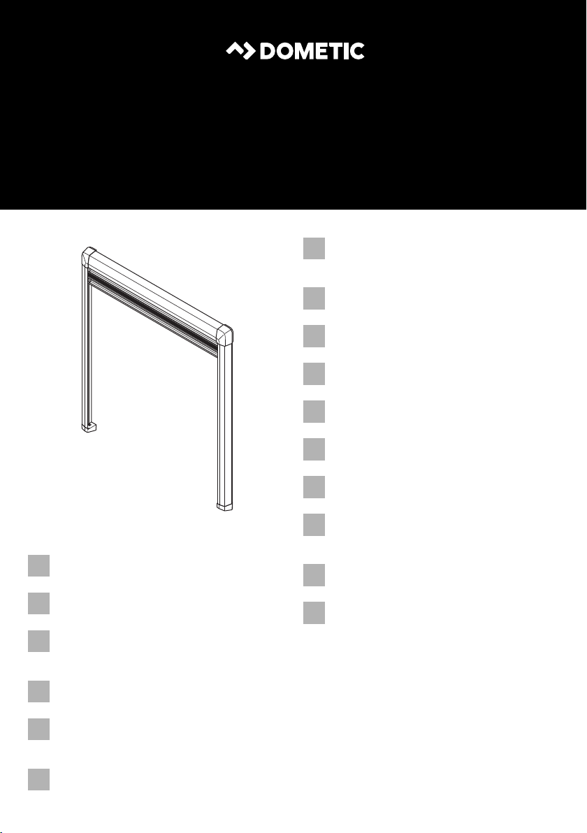
1Scope of delivery
Item in
fig. 1, page 2
1 1 Pleated roller blind
2 2 Cover for the corners
3 2 Cover for the ends
4 1 Bracket for the cassettes
5 1 Countersunk screw 3.5 mm x 16 mm
6 6 Oval-head screw 3.5 mm x 20 mm
7 2 End piece of guide rails for inward mounting
Quantity Description
(only for widths over 1 m)
(only for widths over 1 m)
(front window)
9
Page 10

EN
Intended use DB3H, DB3Y
2 Intended use
The pleated roller blind is suitable for windows in mobile homes or camper vans.
It has an insect screen and a blackout pleated blind.
3 Fitting the roller blind
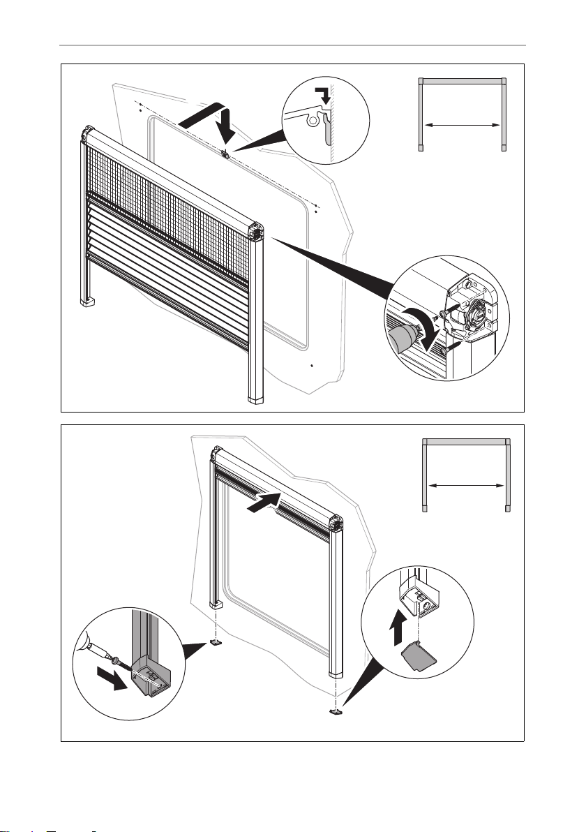
3.1 Fixing the roller blind
The fastening of the roller blind is different for roller blinds that are under 1 m in width
and those that are 1 m in width or wider. Wide roller blinds must have an additional
bracket for the cassette fixed at the top.
NOTICE!
•
A
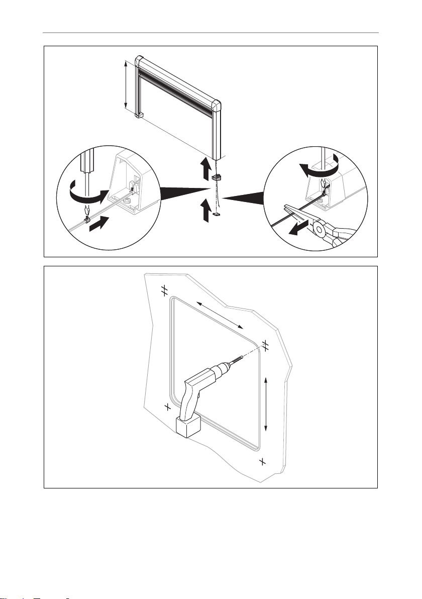
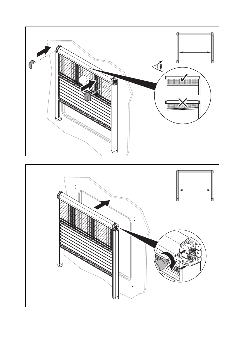
➤ Proceed as illustrated (fig. 2, page 2 to fig. a, page 7).
➤ Align the blind with the window cut-out.
If the screws supplied do not hold in the wall, you must use plugs
suitable for the wall construction.
•
Make sure you do not drill through the wall.
➤ Pre-drill if the wall construction requires this.
➤ Fasten the blind to the wall with the screws.
➤ Fasten the guide rails to the wall with the screws, at right-angles to the cassette.
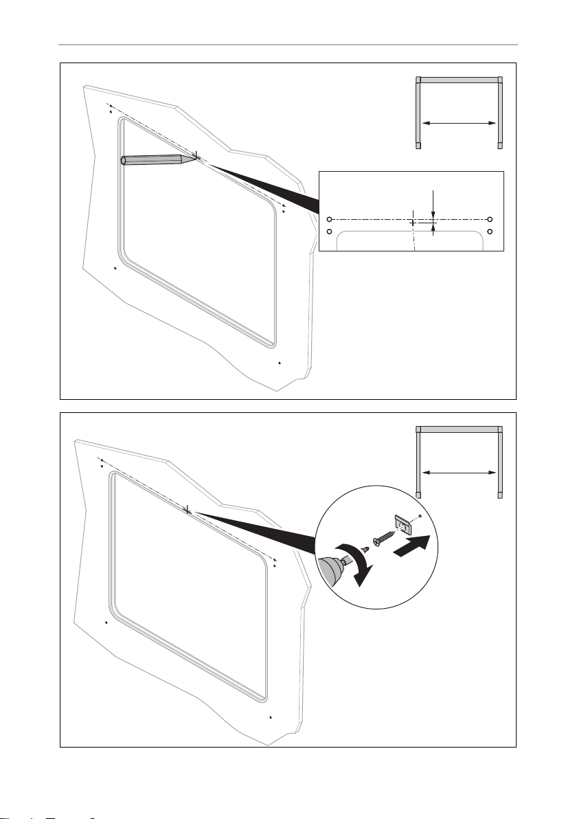
All steps with width specifications must only be performed for roller blinds with the
corresponding width of over 1 m or under 1 m. For roller blinds with a width over 1 m,
the top cassette must be fixed with an additional bracket. Determine the position for
fastening the bracket as illustrated (fig. 5, page 4).
3.2 Adjusting the tension of the roller blinds
NOTICE!
A
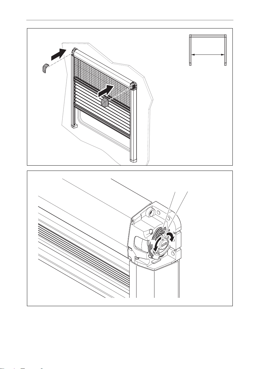
Tensioning the insect screen
➤ Rotate the central part of the tensioning fitting to increase or decrease the tension
of the insect screen (fig. c, page 8).
Always adjust the tension on the right and left in parallel. Otherwise,
damage may be caused to the roller blind in the long term.
10
Page 11

EN
DB3H, DB3Y Using the roller blind
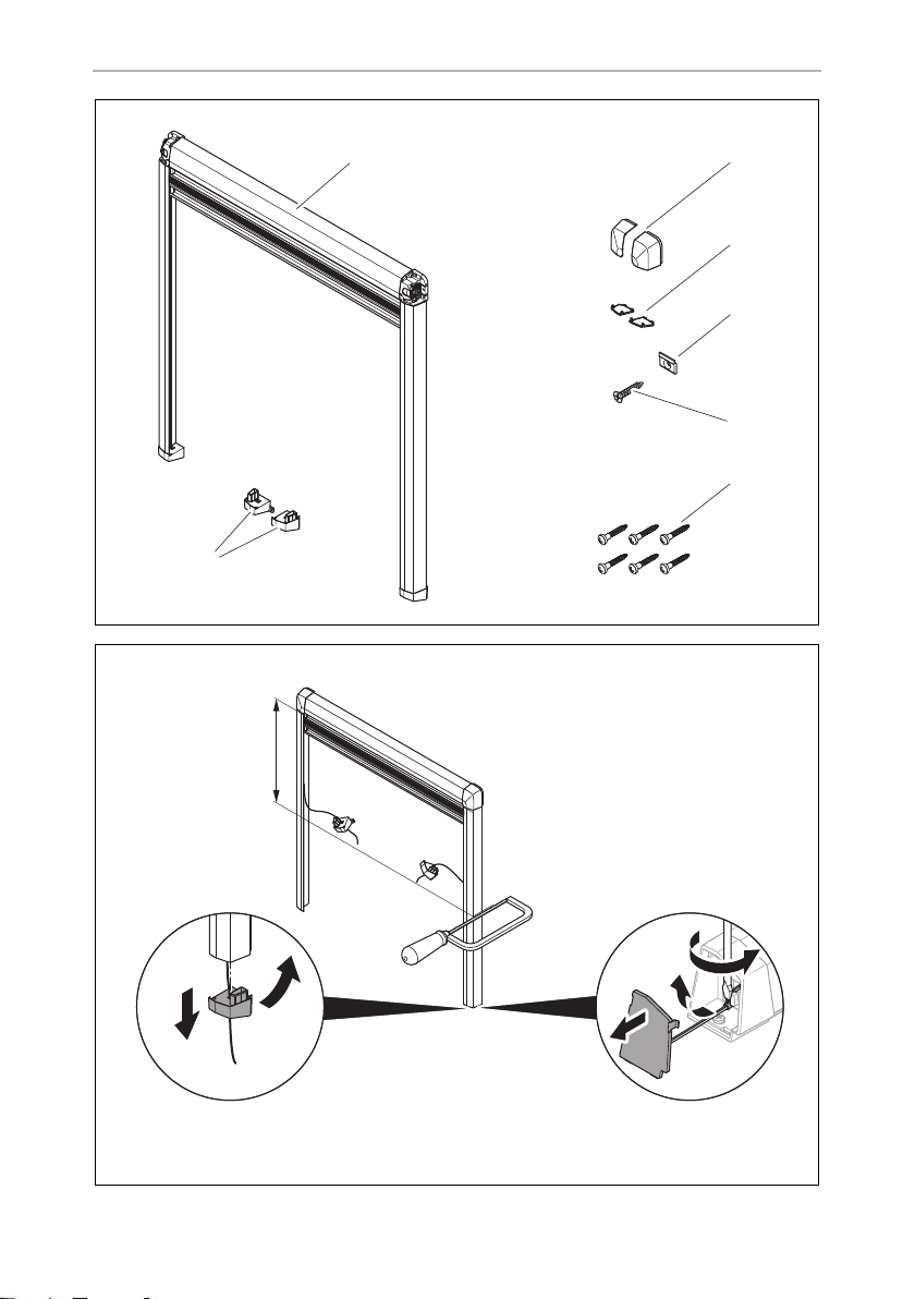
Tensioning the blackout pleated blind
➤ Tension the blackout pleated blind as follows:
– to a certain extent by tensioning the cords (fig. b 1, page 7) with springs
(fig. b 2, page 7), that are located on the right and left of the cassette
or
– at the endpiece of the guide rail (fig. 2, page 2 and fig. 3, page 3)
4 Using the roller blind
4.1 Closing the roller blind
NOTICE! Risk of damage due to a build-up of heat between the
A
➤ Pull the blackout roller blind and the insect screen by the handle strip to the
desired position.
✓ When the tension has been set correctly the roller blinds stay in the closed
position.
roller blind and the window!
In strong sunlight, only close the blackout roller blind two thirds of the
way.
4.2 Opening the roller blind
NOTICE! Risk of damage
A
➤ Pull the blackout roller blind and the insect screen by the handle strip to the
desired, open position.
✓ The handle strips of the roller blinds hold firm in every position.
Never let the blackout roller blind spring back.
5 Troubleshooting
The insect screen or blackout roller blind cannot be moved.
➤ Check the guide rails for dirt.
➤ Clean the guide rails if necessary.
11
Page 12

EN
Cleaning and care DB3H, DB3Y
The tension of the roller blind is insufficient.
➤ Tension the cords at the end of the guide rails or at the springs located on the
right and left of the cassette.
6 Cleaning and care
NOTICE!
A
➤ Occasionally clean the product with a damp cloth.
➤ To prevent material fatigue, do not keep the blind closed for long periods of
time.
➤ If the veh icl e is sta tio nar y fo r lon g pe rio ds o f ti me, pul l up the b lac kou t ro lle r bl ind
until the individual honeycombs are pulled apart slightly. So the honeycomb system is ventilated on both sides to prevent the formation of mildew.
Do not use sharp or hard objects or cleaning agents for cleaning as these
may damage the product.
7Warranty
The statutory warranty period applies. If the product is defective, please contact your
retailer or the manufacturer's branch in your country (see the back of the instruction
manual for the addresses).
For repair and warranty processing, please include the following documents when
you send in the device:
•
A copy of the receipt with purchasing date
•
A reason for the claim or description of the fault
12
Page 13
EN
DB3H, DB3Y Technical data
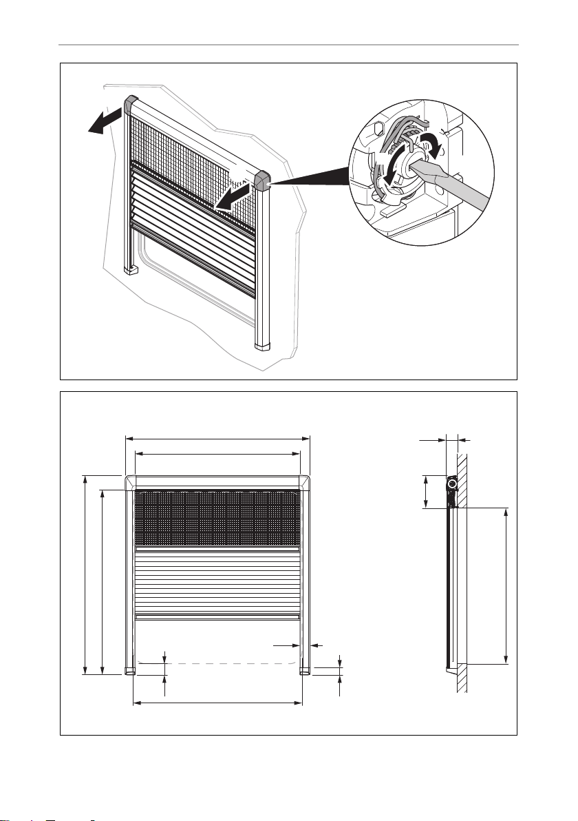
8 Technical data
Item in
fig. d, page 8
Description
A Order dimension, width (length of cassette): E – 15 mm
B Order dimension, height (length of guide rail): F + G – 30 mm
C Width above everything: A + 74 mm
D Height above everything: B + 75 mm
E Width of window cut-out (clearance dimensions)
F Height of window cut-out (clearance dimensions)
G Distance between top of the roller blind and window cut-out:
approx. 115 mm
8.1 Order dimensions
The product is available in the following order dimensions:
Ref. no.
9104121246 485 x 700 mm 559 mm 775 mm 500 mm 615 mm 1.10 kg
9104121247 535 x 700 mm 609 mm 775 mm 550 mm 615 mm 1.15 kg
9104121248 585 x 700 mm 659 mm 775 mm 600 mm 615 mm 1.20 kg
9104121249 635 x 700 mm 709 mm 775 mm 650 mm 615 mm 1.25 kg
9104121250 685 x 700 mm 759 mm 775 mm 700 mm 615 mm 1.30 kg
9104121251 735 x 700 mm 809 mm 775 mm 750 mm 615 mm 1.35 kg
9104121252 785 x 700 mm 859 mm 775 mm 800 mm 615 mm 1.45 kg
9104121253 885 x 700 mm 959 mm 775 mm 900 mm 615 mm 1.55 kg
9104121254 985 x 700 mm 1059 mm 775 mm 1000 mm 615 mm 1.65 kg
9104121255 1085 x 700 mm 1159 mm 775 mm 1100 mm 615 mm 1.75 kg
9104121256 1185 x 700 mm 1259 mm 775 mm 1200 mm 615 mm 1.85 kg
9104121257 1285 x 800 mm 1359 mm 875 mm 1300 mm 715 mm 2.01 kg
9104121258 1385 x 800 mm 1459 mm 875 mm 1400 mm 715 mm 2.09 kg
9104121260 1485 x 800 mm 1559 mm 875 mm 1500 mm 715 mm 2.25 kg
9104121262 1585 x 800 mm 1659 mm 875 mm 1600 mm 715 mm 2.41 kg
Order size
Width A x height B
C D E F Wei ght
13
Page 14

DE
Lieferumfang DB3H, DB3Y
Bitte lesen Sie diese Anleitung vor Einbau und Inbetriebnahme sorgfältig
durch und bewahren Sie sie auf. Geben Sie sie im Falle einer Weitergabe
des Produktes an den Nutzer weiter.
Inhalt
1 Lieferumfang . . . . . . . . . . . . . . . . . . . . . . . . . . . . . . . . . . . . . . . . . . . . . . . . . . 14
2 Bestimmungsgemäßer Gebrauch . . . . . . . . . . . . . . . . . . . . . . . . . . . . . . . . . 15
3 Rollo montieren. . . . . . . . . . . . . . . . . . . . . . . . . . . . . . . . . . . . . . . . . . . . . . . .15
4 Rollo benutzen . . . . . . . . . . . . . . . . . . . . . . . . . . . . . . . . . . . . . . . . . . . . . . . . 16
5 Störungsbeseitigung . . . . . . . . . . . . . . . . . . . . . . . . . . . . . . . . . . . . . . . . . . .17
6 Reinigung und Pflege . . . . . . . . . . . . . . . . . . . . . . . . . . . . . . . . . . . . . . . . . . .17
7 Gewährleistung. . . . . . . . . . . . . . . . . . . . . . . . . . . . . . . . . . . . . . . . . . . . . . . . 18
8 Technische Daten . . . . . . . . . . . . . . . . . . . . . . . . . . . . . . . . . . . . . . . . . . . . . .18
1 Lieferumfang
Pos. in
Abb. 1, Seite 2
1 1 Plissérollo
2 2 Abdeckung für die Ecken
3 2 Abdeckung für die Endstücke
4 1 Halterung für die Kassetten
5 1 Senkkopfschraube 3,5 mm x 16 mm
6 6 Linsenkopfschraube 3,5 mm x 20 mm
7 2 Endstück Führungsschiene für Innenbefestigung
14
Anzahl Beschreibung
(nur bei Breiten ab 1 m)
(nur bei Breiten ab 1 m)
(Bugfenster)
Page 15

DE
DB3H, DB3Y Bestimmungsgemäßer Gebrauch
2 Bestimmungsgemäßer Gebrauch
Das Plisseerollo ist geeignet für Fenster in Wohnmobilen oder Wohnwagen. Es
besitzt ein Insektenschutzrollo und ein Verdunkelungsplissee.
3 Rollo montieren
3.1 Rollo befestigen
Die Befestigung des Rollos unterscheidet sich für Rollos unter 1 m Breite und ab 1 m
Breite. Bei breiten Rollos muss oben eine zusätzliche Halterung für die Kassette montiert werden.
ACHTUNG!
•
A
➤ Gehen Sie vor wie dargestellt (Abb. 2, Seite 2 bis Abb. a, Seite 7).
➤ Richten Sie das Rollo am Fensterausschnitt aus.
Falls die mitgelieferten Schrauben nicht in der Wand halten,
benutzen Sie für die Wandkonstruktion passende Dübel.
•
Stellen Sie sicher, dass Sie die Wand nicht durchbohren.
➤ Bohren Sie vor, falls die Wandkonstruktion das erfordert.
➤ Befestigen Sie das Rollo mit den Schrauben an der Wand.
➤ Befestigen Sie die Führungsschienen rechtwinkelig zur Kassette mit den
Schrauben an der Wand.
Alle mit Breitenangaben versehenen Schritte müssen nur für Rollos mit der entsprechenden Breite von über 1 m oder unter 1 m ausgeführt werden. Bei Rollos mit einer
Breite von über 1 m muss die obere Kassette mit einer zusätzlichen Halterung befestigt werden. Ermitteln Sie den Punkt für die Befestigung des Halters wie dargestellt
(Abb. 5, Seite 4).
15
Page 16

DE
Rollo benutzen DB3H, DB3Y
3.2 Spannung der Rollos einstellen
ACHTUNG!
A
Insektenschutzrollo spannen
➤ Drehen Sie den mittleren Teil der Spannvorrichtung, um die Spannung des Insek-
tenschutzes zu erhöhen oder zu verringern (Abb. c, Seite 8).
Verdunkelungsrollo spannen
➤ Spannen Sie das Verdunkelungsrollo wie folgt:
– in begrenztem Umfang durch die Spannung der Schnüre (Abb. b 1, Seite 7)
oder
– am Endstück (Abb. 2, Seite 2 und Abb. 3, Seite 3)
Stellen Sie die Spannung immer rechts und links parallel ein. Es kann
sonst auf Dauer zu Schäden an dem Rollo kommen.
über Spannfedern (Abb. b 2, Seite 7), die rechts und links an der Kassette
zu finden sind
4 Rollo benutzen
4.1 Rollo schließen
ACHTUNG! Beschädigungsgefahr durch Hitzestau zwischen
A
➤ Ziehen Sie das Verdunkelungsrollo und das Insektenschutzrollo an der Griffleiste
in die gewünschte Position.
✓ Bei der richtigen Einstellung der Spannung halten die Rollos in der geschlosse-
nen Position.
16
Rollo und Glasscheibe!
Bei starker Sonneneinstrahlung dürfen Sie das Verdunkelungsrollo nur
zu zwei Dritteln schließen.
Page 17

DE
DB3H, DB3Y Störungsbeseitigung
4.2 Rollo öffnen
ACHTUNG! Beschädigungsgefahr
A
➤ Ziehen Sie das Verdunkelungsrollo und das Insektenschutzrollo an der Griffleiste
in die gewünschte, offene Position.
✓ Die Griffleisten der Rollos halten in jeder Position.
Lassen Sie das Verdunklungsrollo niemals zurückschnellen.
5 Störungsbeseitigung
Das Insektenschutz- oder Verdunkelungsrollo lassen sich nicht
verschieben
➤ Prüfen Sie die Führungsschienen auf Verschmutzungen.
➤ Reinigen Sie gegebenenfalls die Führungsschienen.
Die Spannung der Rollos ist zu gering
➤ Spannen Sie die Schnüre am Endstück der Führungsschiene oder an den Spann-
federn, die rechts und links an der Kassette zu finden sind.
6 Reinigung und Pflege
ACHTUNG!
A
➤ Reinigen Sie das Produkt gelegentlich mit einem feuchten Tuch.
➤ Halten Sie das Rollo nicht über einen längeren Zeitraum geschlossen, um
Materialermüdung zu vermeiden.
➤ Bei längerem Stillstand des Fahrzeuges fahren Sie das Verdunkelungsrollo so
weit aus, bis sich die einzelnen Waben leicht auseinanderziehen. So ist die
Wabenstruktur beidseitig belüftet und Sie beugen Schimmelbildung vor.
Keine scharfen oder harten Gegenstände oder Reinigungsmittel zur
Reinigung verwenden, da dies zu einer Beschädigung des Produktes
führen kann.
17
Page 18

DE
Gewährleistung DB3H, DB3Y
7Gewährleistung
Es gilt die gesetzliche Gewährleistungsfrist. Sollte das Produkt defekt sein, wenden
Sie sich bitte an Ihren Fachhändler oder an die Niederlassung des Herstellers in
Ihrem Land (Adressen siehe Rückseite der Anleitung).
Zur Reparatur- bzw. Gewährleistungsbearbeitung müssen Sie folgende Unterlagen
mitschicken:
•
eine Kopie der Rechnung mit Kaufdatum,
•
einen Reklamationsgrund oder eine Fehlerbeschreibung.
8 Technische Daten
Pos. in
Abb. d, Seite 8
A
B
C
D
E
F
G Abstand von Oberkante Rollo zu Fensterausschnitt: ca. 115 mm
Bezeichnung
Bestellmaß Breite (Länge Kassette): E – 15 mm
Bestellmaß Höhe (Länge Führungsschiene): F + G – 30 mm
Breite über alles: A + 74 mm
Höhe über alles: B + 75 mm
Breite Fensterausschnitt (lichtes Maß)
Höhe Fensterausschnitt (lichtes Maß)
18
Page 19

DE
DB3H, DB3Y Technische Daten
8.1 Bestellmaße
Das Produkt ist in folgenden Bestellmaßen erhältlich:
Art.-Nr.
9104121246 485 x 700 mm 559 mm 775 mm 500 mm 615 mm 1,10 kg
9104121247 535 x 700 mm 609 mm 775 mm 550 mm 615 mm 1,15 kg
9104121248 585 x 700 mm 659 mm 775 mm 600 mm 615 mm 1,20 kg
9104121249 635 x 700 mm 709 mm 775 mm 650 mm 615 mm 1,25 kg
9104121250 685 x 700 mm 759 mm 775 mm 700 mm 615 mm 1,30 kg
9104121251 735 x 700 mm 809 mm 775 mm 750 mm 615 mm 1,35 kg
9104121252 785 x 700 mm 859 mm 775 mm 800 mm 615 mm 1,45 kg
9104121253 885 x 700 mm 959 mm 775 mm 900 mm 615 mm 1,55 kg
9104121254 985 x 700 mm 1059 mm 775 mm 1000 mm 615 mm 1,65 kg
9104121255 1085 x 700 mm 1159 mm 775 mm 1100 mm 615 mm 1,75 kg
9104121256 1185 x 700 mm 1259 mm 775 mm 1200 mm 615 mm 1,85 kg
9104121257 1285 x 800 mm 1359 mm 875 mm 1300 mm 715 mm 2,01 kg
9104121258 1385 x 800 mm 1459 mm 875 mm 1400 mm 715 mm 2,09 kg
9104121260 1485 x 800 mm 1559 mm 875 mm 1500 mm 715 mm 2,25 kg
9104121262 1585 x 800 mm 1659 mm 875 mm 1600 mm 715 mm 2,41 kg
Bestellmaß
Breite A x Höhe B
C D E F Gewicht
19
Page 20

FR
Contenu de la livraison DB3H, DB3Y
Veuillez lire attentivement cette notice avant le montage et la mise en
service. Veuillez ensuite la conserver. En cas de passer le produit, veuillez
le transmettre au nouvel acquéreur.
Sommaire
1 Contenu de la livraison . . . . . . . . . . . . . . . . . . . . . . . . . . . . . . . . . . . . . . . . . 20
2 Usage conforme . . . . . . . . . . . . . . . . . . . . . . . . . . . . . . . . . . . . . . . . . . . . . . .21
3 Montage du store à enrouleur . . . . . . . . . . . . . . . . . . . . . . . . . . . . . . . . . . . .21
4 Utilisation du store à enrouleur. . . . . . . . . . . . . . . . . . . . . . . . . . . . . . . . . . . 22
5 Guide de dépannage . . . . . . . . . . . . . . . . . . . . . . . . . . . . . . . . . . . . . . . . . . 23
6 Nettoyage et entretien . . . . . . . . . . . . . . . . . . . . . . . . . . . . . . . . . . . . . . . . . 23
7 Garantie. . . . . . . . . . . . . . . . . . . . . . . . . . . . . . . . . . . . . . . . . . . . . . . . . . . . . 23
8 Caractéristiques techniques . . . . . . . . . . . . . . . . . . . . . . . . . . . . . . . . . . . . . 24
1 Contenu de la livraison
Position dans
fig. 1, page 2
20
Quantité Description
1 1 Store souple à enrouleur
2 2 Cache pour les coins
3 2 Cache pour les extrémités
4 1 Support pour les cassettes
(uniquement pour largeur supérieure à 1 m)
5 1 Vis à tête fraisée 3,5 mm x 16 mm
(uniquement pour largeur supérieure à 1 m)
6 6 Vis à tête cylindrique 3,5 mm x 20 mm
7 2 Extrémité de rails de guidage pour montage vers
l’intérieur (pare-brise avant)
Page 21

FR
DB3H, DB3Y Usage conforme
2Usage conforme
Le store souple est conçu pour les caravanes et les camping-cars. Il comprend une
moustiquaire et un store souple occultant.
3 Montage du store à enrouleur
3.1 Fixation du store à enrouleur
La fixation des stores varie en fonction de leur largeur, à savoir s’ils font moins d’1 m
de large ou s’ils font 1 m ou plus. Pour les stores larges, un support supplémentaire
de fixation des cassettes doit être installé en haut.
AVIS !
•
A
➤ Suivre la procédure illustrée (fig. 2, page 2 à fig. a, page 7).
➤ Tenez le store dans l’axe de la découpe de fenêtre.
Si les vis fournies ne peuvent pas être fixées au mur, vous devez
utiliser des chevilles adaptées à la nature du mur.
•
Veillez à ne pas perforer le mur.
➤ Effectuez un préperçage si la nature du mur l’exige.
➤ Fixez le store au mur à l’aide de vis.
➤ Fixez les rails de guidage au mur à l’aide des vis, et ce, perpendiculairement à la
cassette.
Toutes les étapes assorties d’indications de largeur ne doivent être effectuées que
pour les stores correspondants de largeur supérieure ou inférieure à 1 m. Pour les
stores de plus de 1 mètre de large, le haut de la cassette doit être fixé à l’aide d’un
support supplémentaire. Définissez la position de fixation du support comme indiqué (fig. 5, page 4).
3.2 Réglage de la tension des stores
AVIS !
A
Réglez toujours la tension simultanément à droite et à gauche. Le store
risquerait sinon d’être endommagé durablement.
21
Page 22

FR
Utilisation du store à enrouleur DB3H, DB3Y
Tension de la moustiquaire
➤ Pour augmenter ou diminuer la tension de la moustiquaire, faites tourner la partie
centrale du dispositif tendeur (fig. c, page 8).
Tension du store souple occultant
➤ Tendez le store souple occultant de la manière suivantes :
– jusqu’à un certain niveau à l’aide de tendeurs (fig.b 1, page 7) à ressorts
(fig. b 2, page 7) situés de part et d’autre de la cassette
ou
– à l'extrémité du rail de guidage (fig. 2, page 2 et fig. 3, page 3)
4 Utilisation du store à enrouleur
4.1 Fermeture du store à enrouleur
AVIS ! Risque d’endommagement en raison de l’accumulation
A
de chaleur entre le store et la vitre.
En cas de fort rayonnement solaire, vous ne devez fermer le store occultant qu’aux deux tiers.
➤ Tirez sur les poignées du store occultant et de la moustiquaire pour les amener
dans la position souhaitée.
✓ Si la tension a été correctement réglée, les stores restent en position fermée.
4.2 Ouverture des stores
AVIS ! Risque d’endommagement
A
➤ Tirez sur les poignées du store occultant et de la moustiquaire pour les amener
dans la position souhaitée ouverte.
✓ Les poignées des stores restent bien en place dans toutes les positions.
22
Ne laissez jamais le store occultant se rabattre seul.
Page 23

FR
DB3H, DB3Y Guide de dépannage
5 Guide de dépannage
La moustiquaire ou le store occultant ne coulissent plus.
➤ Contrôlez l’état de propreté des glissières latérales.
➤ Nettoyez les glissières latérales, le cas échéant.
La tension du store est trop faible.
➤ Serrez les tendeurs à l'extrémité des rails de guidage ou au niveau des ressorts
situés de part et d’autre de la cassette.
6 Nettoyage et entretien
AVIS !
A
➤ Nettoyez le produit avec un tissu humide.
➤ Ne laissez pas le store fermé pendant une période prolongée pour éviter que le
matériau ne s’use.
N’utilisez aucun objet coupant ou dur, ni de détergents pour le
nettoyage. Cela pourrait endommager le produit.
➤ En cas d’immobilisation prolongée du véhicule, remontez le store occultant de
manière à ce que les lamelles soit légèrement étirées. Les lamelles sont ainsi ventilées des deux côtés pour éviter la formation de moisissures.
7 Garantie
Le délai légal de garantie s'applique. Si le produit s'avérait défectueux, veuillez vous
adresser à la filiale du fabricant située dans votre pays (voir adresses au verso du
présent manuel) ou à votre revendeur spécialisé.
Veuillez y joindre les documents suivants pour la gestion des réparations et de la
garantie :
•
une copie de la facture avec la date d'achat,
•
le motif de la réclamation ou une description du dysfonctionnement.
23
Page 24

FR
Caractéristiques techniques DB3H, DB3Y
8 Caractéristiques techniques
Position dans
fig. d, page 8
Description
A Dimensions de commande, largeur (longueur de la cassette) :
E – 15 mm
B Dimensions de commande, hauteur (longueur du rail de guidage) :
F + G – 30 mm
C Largeur hors tout : A + 74 mm
D Hauteur hors tout : B + 75 mm
E Largeur de la découpe de fenêtre (découpe utile)
F Hauteur de la découpe de fenêtre (découpe utile)
G Distance entre le haut du store et la découpe de fenêtre : environ
115 mm
8.1 Dimensions de commande
Le produit est disponible dans les dimensions suivantes :
Taille commandée
N° d’article
9104121246 485 x 700 mm 559 mm 775 mm 500 mm 615 mm 1,10 kg
9104121247 535 x 700 mm 609 mm 775 mm 550 mm 615 mm 1,15 kg
9104121248 585 x 700 mm 659 mm 775 mm 600 mm 615 mm 1,20 kg
9104121249 635 x 700 mm 709 mm 775 mm 650 mm 615 mm 1,25 kg
9104121250 685 x 700 mm 759 mm 775 mm 700 mm 615 mm 1,30 kg
9104121251 735 x 700 mm 809 mm 775 mm 750 mm 615 mm 1,35 kg
9104121252 785 x 700 mm 859 mm 775 mm 800 mm 615 mm 1,45 kg
9104121253 885 x 700 mm 959 mm 775 mm 900 mm 615 mm 1,55 kg
9104121254 985 x 700 mm 1 059 mm 775 mm 1000 mm 615 mm 1,65 kg
9104121255 1 085 x 700 mm 1 159 mm 775 mm 1 100 mm 615 mm 1,75 kg
9104121256 1 185 x 700 mm 1 259 mm 775 mm 1 200 mm 615 mm 1,85 kg
9104121257 1 285 x 800 mm 1 359 mm 875 mm 1 300 mm 715 mm 2,01 kg
9104121258 1 385 x 800 mm 1 459 mm 875 mm 1 400 mm 715 mm 2,09 kg
9104121260 1 485 x 800 mm 1 559 mm 875 mm 1 500 mm 715 mm 2,25 kg
9104121262 1 585 x 800 mm 1 659 mm 875 mm 1 600 mm 715 mm 2,41 kg
largeur A x
hauteur B
C D E F Poids
24
Page 25

ES
DB3H, DB3Y Volumen de entrega
Lea detenidamente estas instrucciones antes de llevar a cabo la instalación
y puesta en funcionamiento, y consérvelas en un lugar seguro. En caso de
vender o entregar el producto a otra persona, entregue también estas
instrucciones.
Índice
1 Volumen de entrega . . . . . . . . . . . . . . . . . . . . . . . . . . . . . . . . . . . . . . . . . . . 25
2 Uso previsto . . . . . . . . . . . . . . . . . . . . . . . . . . . . . . . . . . . . . . . . . . . . . . . . . 26
3 Instalación del estor . . . . . . . . . . . . . . . . . . . . . . . . . . . . . . . . . . . . . . . . . . . 26
4 Uso del estor . . . . . . . . . . . . . . . . . . . . . . . . . . . . . . . . . . . . . . . . . . . . . . . . . 27
5 Solución de averías . . . . . . . . . . . . . . . . . . . . . . . . . . . . . . . . . . . . . . . . . . . . 28
6 Limpieza y cuidados . . . . . . . . . . . . . . . . . . . . . . . . . . . . . . . . . . . . . . . . . . . 28
7 Garantía . . . . . . . . . . . . . . . . . . . . . . . . . . . . . . . . . . . . . . . . . . . . . . . . . . . . . 28
8 Datos técnicos. . . . . . . . . . . . . . . . . . . . . . . . . . . . . . . . . . . . . . . . . . . . . . . . 29
1 Volumen de entrega
Elemento en la
fig. 1, página 2
1 1 Estor con plisado
2 2 Embellecedor para las esquinas
3 2 Embellecedor para los extremos
4 1 Soporte para los cajones
5 1 Tornillo avellanado 3,5 mm x 16 mm
6 6 Tornillo de cabeza ovalada 3,5 mm x 20 mm
7 2 Pieza del extremo de los carriles guía para el
Cantidad Descripción
(solo para anchuras superiores a 1 m)
(solo para anchuras superiores a 1 m)
montaje interno (ventana frontal)
25
Page 26

ES
Uso previsto DB3H, DB3Y
2 Uso previsto
El estor con plisado es apto para ventanas de caravanas y autocaravanas. Dispone de
mosquitera y estor oscurecedor con plisado.
3 Instalación del estor
3.1 Fijación del estor
El sistema de sujeción de los estores de menos de 1 m de ancho es distinto de los de
un 1 m o más. Los estores anchos necesitan un soporte adicional para el cajón fijado
en la parte superior.
¡AVISO!
•
A
➤ Proceda tal y como se indica en la ilustración (fig. 2, página 2 to fig. a,
página 7).
Si los tornillos suministrados no pueden fijarse a la pared, deberá
utilizar tacos adecuados en función de cómo esté construida dicha
pared.
•
Preste atención a no taladrar completamente la pared.
➤ Alinee el estor con el hueco de la ventana.
➤ Taladre previamente cuando la construcción de la pared lo permita.
➤ Fije el estor a la pared con los tornillos.
➤ Fije los carriles guía en ángulo recto con respecto al cajón con los tornillos a la
pared.
Todos los pasos con especificaciones de anchura solo deben realizarse para estores
con la anchura correspondiente de más de 1 m o menos de 1 m. Para estores con una
anchura superior a 1 m, el cajón superior debe estar fijado con un soporte adicional.
Marque los puntos de colocación de los soportes tal como se indica (fig. 5,
página 4).
3.2 Ajuste de la tensión de los estores
¡AVISO!
A
Ajuste siempre la tensión simultáneamente en la derecha y en la
izquierda. De lo contrario, el estor podría estropearse a largo plazo.
26
Page 27

ES
DB3H, DB3Y Uso del estor
Ten sa r la mo squ it er a
➤ Rote la parte central del mecanismo tensor para aumentar o reducir la tensión de
la mosquitera (fig. c, página 8).
Tensar el estor oscurecedor con plisado
➤ Tensar el estor oscurecedor con plisado como se indica a continuación:
– tensando las cuerdas hasta cierto punto (fig. b 1, página 7) con muelles
(fig. b 2, página 7), que están situados en el lado derecho e izquierdo del
cajón
O bien
– en la pieza terminal del carril guía (fig. 2, página 2 y fig. 3, página 3)
4Uso del estor
4.1 Cierre del estor
¡AVISO! El calor acumulado entre el estor y la ventana puede
A
producir daños.
Si la luz solar es muy intensa, cierre el estor oscurecedor solamente hasta
dos tercios de su altura.
➤ Tire del estor oscurecedor y de la mosquitera por la varilla tiradora hasta la posi-
ción deseada.
✓ Si la tensión está correctamente fijada, los estores se quedarán en la posición
deseada.
4.2 Apertura del estor
¡AVISO! Peligro de daños materiales
A
➤ Tire del estor oscurecedor y de la mosquitera por la varilla tiradora hasta la posi-
ción abierta deseada.
✓ Las varillas tiradoras de los estores se mantienen fijas en cualquier posición.
No deje que el estor oscurecedor vuelva solo a su posición original.
27
Page 28

ES
Solución de averías DB3H, DB3Y
5 Solución de averías
La mosquitera o el estor oscurecedor no se pueden mover.
➤ Compruebe si hay suciedades en los carriles guía.
➤ En caso necesario limpie los carriles guía.
La tensión del estor es insuficiente.
➤ Tense las cuerdas en el extremos de los carriles guía o en los muelles situados en
el lado derecho e izquierdo del cajón.
6 Limpieza y cuidados
¡AVISO!
A
➤ Limpie de vez en cuando el producto con un paño húmedo.
➤ No deje el estor cerrado durante demasiado tiempo para evitar que los materia-
les se deterioren.
No utilice ningún objeto o producto de limpieza corrosivo o duro en la
limpieza, ya que podría dañar el producto.
➤ En caso de una parada prolongada del vehículo, levante el estor de oscureci-
miento lo máximo posible hasta que los plisados queden ligeramente separados
entre sí. De esa forma el sistema de plisado se ventila en ambos lados para evitar
la formación de moho.
7 Garantía
Rige el plazo de garantía legal. Si el producto presenta algún defecto, diríjase a su
establecimiento especializado o a la sucursal del fabricante de su país (ver
direcciones en el dorso de estas instrucciones).
Para la tramitación de la reparación y de la garantía debe enviar también los
siguientes documentos:
•
una copia de la factura con fecha de compra,
•
el motivo de la reclamación o una descripción de la avería.
28
Page 29

ES
DB3H, DB3Y Datos técnicos
8 Datos técnicos
Elemento en la
fig. d, página 8
Descripción
A Dimensión de pedido, anchura (longitud del cajón): E – 15 mm
B Dimensión de pedido, altura (longitud del carril guía): F + G – 30 mm
C Anchura sobre todo: A + 74 mm
D Altura sobre todo: B + 75 mm
E Anchura del hueco de ventana (dimensiones del espacio libre)
F Altura del hueco de ventana (dimensiones del espacio libre)
G Distancia entre la parte superior del estor y la hueco de la ventana:
aprox. 115 mm
8.1 Dimensiones de pedido
El producto está disponible en las siguientes dimensiones de pedido:
N.° de art.
9104121246 485 x 700 mm 559 mm 775 mm 500 mm 615 mm 1,10 kg
9104121247 535 x 700 mm 609 mm 775 mm 550 mm 615 mm 1,15 kg
9104121248 585 x 700 mm 659 mm 775 mm 600 mm 615 mm 1,20 kg
9104121249 635 x 700 mm 709 mm 775 mm 650 mm 615 mm 1,25 kg
9104121250 685 x 700 mm 759 mm 775 mm 700 mm 615 mm 1,30 kg
9104121251 735 x 700 mm 809 mm 775 mm 750 mm 615 mm 1,35 kg
9104121252 785 x 700 mm 859 mm 775 mm 800 mm 615 mm 1,45 kg
9104121253 885 x 700 mm 959 mm 775 mm 900 mm 615 mm 1,55 kg
9104121254 985 x 700 mm 1059 mm 775 mm 1000 mm 615 mm 1,65 kg
9104121255 1085 x 700 mm 1159 mm 775 mm 1100 mm 615 mm 1,75 kg
9104121256 1185 x 700 mm 1259 mm 775 mm 1200 mm 615 mm 1,85 kg
9104121257 1285 x 800 mm 1359 mm 875 mm 1300 mm 715 mm 2,01 kg
9104121258 1385 x 800 mm 1459 mm 875 mm 1400 mm 715 mm 2,09 kg
9104121260 1485 x 800 mm 1559 mm 875 mm 1500 mm 715 mm 2,25 kg
9104121262 1585 x 800 mm 1659 mm 875 mm 1600 mm 715 mm 2,41 kg
Tamaño de pedido
ancho A x altura B
C D E F Peso
29
Page 30

PT
Material fornecido DB3H, DB3Y
Por favor, leia atentamente este manual antes da montagem e colocação
em funcionamento do aparelho e guarde-o em local seguro. Em caso de
transmissão do produto, entregue o manual ao novo utilizador.
Índice
1 Material fornecido. . . . . . . . . . . . . . . . . . . . . . . . . . . . . . . . . . . . . . . . . . . . . 30
2 Utilização adequada . . . . . . . . . . . . . . . . . . . . . . . . . . . . . . . . . . . . . . . . . . . .31
3 Montar a persiana . . . . . . . . . . . . . . . . . . . . . . . . . . . . . . . . . . . . . . . . . . . . . . 31
4 Utilizar a persiana . . . . . . . . . . . . . . . . . . . . . . . . . . . . . . . . . . . . . . . . . . . . . 32
5 Resolução de falhas. . . . . . . . . . . . . . . . . . . . . . . . . . . . . . . . . . . . . . . . . . . . 33
6 Limpeza e manutenção . . . . . . . . . . . . . . . . . . . . . . . . . . . . . . . . . . . . . . . . . 33
7 Garantia . . . . . . . . . . . . . . . . . . . . . . . . . . . . . . . . . . . . . . . . . . . . . . . . . . . . . 33
8 Dados técnicos . . . . . . . . . . . . . . . . . . . . . . . . . . . . . . . . . . . . . . . . . . . . . . . 34
1 Material fornecido
Posição na
fig. 1, página 2
1 1 Persiana plissada
2 2 Tampa para os cantos
3 2 Tampa para as extremidades
4 1 Suporte para as caixas
5 1 Parafusos de cabeça escareada 3,5 mm x 16 mm
6 6 Parafuso de cabeça oval 3,5 mm x 20 mm
7 2 Extremidade das calhas de guia para montagem
30
Quantidade Designação
(apenas para larguras superiores a 1 m)
(apenas para larguras superiores a 1 m)
interior (para-brisas)
Page 31

PT
DB3H, DB3Y Utilização adequada
2Utilização adequada
A persiana plissada é adequada para janelas de caravanas ou autocaravanas.
Tem uma estrutura de proteção contra insetos e uma persiana plissada de escurecimento.
3Montar a persiana
3.1 Fixar a persiana
A fixação da persiana é diferente para persianas com menos de 1 m de largura e para
as que tenham uma largura de 1 m ou superior. As persianas largas devem ter um
suporte adicional para a caixa, fixado em cima.
NOTA!
•
A
➤ Proceda como ilustrado (fig. 2, página 2 a fig. a, página 7).
➤ Alinhe a persiana com a secção da janela.
Se os parafusos fornecidos não ficarem fixados à parede, terá de
utilizar buchas apropriadas para a estrutura da parede.
•
Preste atenção para não furar a parede.
➤ Se a construção da parede o exigir, faça furos previamente.
➤ Fixe a persiana à parede com os parafusos.
➤ Fixe as calhas de guia com os parafusos à parede, em ângulos retos em relação
à caixa.
Os passos com especificações de largura devem ser realizados apenas para as persianas com a largura correspondente, superior a 1 m ou inferior a 1 m. Para as persianas com uma largura superior a 1 m, a caixa superior deve ser fixada com um suporte
adicional. Determine a posição para fixar o suporte conforme ilustrado (fig. 5,
página 4).
3.2 Ajustar a tensão das persianas
NOTA!
A
Ajuste sempre a tensão à esquerda e à direita paralelamente. Caso
contrário, poderá causar danos a longo prazo na persiana.
31
Page 32

PT
Utilizar a persiana DB3H, DB3Y
Ajustar a tensão da estrutura de proteção contra insetos
➤ Rode a parte central do encaixe tensor para aumentar ou reduzir a tensão da
estrutura de proteção contra insetos (fig. c, página 8).
Ajustar a tensão da persiana plissada de escurecimento
➤ Para ajustar a tensão da persiana plissada de escurecimento, proceda da
seguinte forma:
– de forma limitada, ajuste a tensão dos fios (fig. b 1, página 7) com as molas
(fig. b 2, página 7) que se encontram à direita e à esquerda da caixa
ou
– na extremidade da calha de guia (fig. 2, página 2 e fig. 3, página 3)
4 Utilizar a persiana
4.1 Fechar a persiana
NOTA! Perigo de danos devido à acumulação de calor entre a
A
persiana e o vidro!
Em caso de radiação solar forte, a persiana de escurecimento só deve
ser fechada até dois terços.
➤ Puxe a persiana de escurecimento e a estrutura de proteção contra insetos pela
barra de abertura/fecho até à posição pretendida.
✓ Quando a tensão for ajustada corretamente, as persianas mantêm-se na posição
fechada.
4.2 Abrir as persianas
NOTA! Perigo de danos
A
➤ Puxe a persiana de escurecimento e a estrutura de proteção contra insetos pela
barra de abertura/fecho até à posição aberta pretendida.
✓ As barras de abertura/fecho das persianas mantêm-se firmes em todas as posi-
ções.
Nunca permita que a persiana de escurecimento se feche subitamente.
32
Page 33

PT
DB3H, DB3Y Resolução de falhas
5 Resolução de falhas
Não é possível deslocar a estrutura de proteção contra insetos ou a persiana de escurecimento.
➤ Verifique se as calhas de guia estão sujas.
➤ Limpe as calhas de guia, se necessário.
A tensão da persiana não é suficiente.
➤ Aumente a tensão dos fios na extremidade das calhas de guia ou nas molas que
se encontram à direita e à esquerda da caixa.
6 Limpeza e manutenção
NOTA!
A
➤ De vez em quando, limpe o aparelho com um pano húmido.
➤ Não mantenha a persiana fechada durante um período de tempo prolongado
para evitar desgaste do material.
Não utilizar objectos afiados ou duros ou agentes de limpeza para
a limpeza, uma vez que podem ser causados danos no produto.
➤ Em caso de paragem prolongada do veículo, puxe a persiana de escurecimento
para cima até os diversos favos ficarem ligeiramente afastados uns dos outros.
Deste modo, o sistema de favos é ventilado de ambos os lados, prevenindo a formação de bolor.
7 Garantia
É válido o prazo de garantia legal. Se o produto estiver com defeito, por favor,
dirija-se ao seu revendedor ou à representaçãodo fabricante no seu país (endereços,
ver verso do manual).
Para fins de reparação ou de garantia, terá de enviar os seguintes documentos em
conjunto:
•
uma cópia da factura com a data de aquisição,
•
um motivo de reclamação ou uma descrição da falha.
33
Page 34

PT
Dados técnicos DB3H, DB3Y
8Dados técnicos
Posição na
fig. d, página 8
Designação
A Dimensão de encomenda, largura (comprimento da caixa):
E – 15 mm
B Dimensão de encomenda, altura (comprimento da calha de guia):
F + G – 30 mm
C Largura sobre tudo: A + 74 mm
D Altura sobre tudo: B + 75mm
E Largura da secção da janela (dimensões da distância livre)
F Altura da secção da janela (dimensões da distância livre)
G Distância entre a parte superior da persiana e a secção da janela:
aprox. 115 mm
8.1 Dimensões de encomenda
O produto está disponível com as seguintes dimensões de encomenda:
Ta m a n h o
N.º art.
9104121246 485 x 700 mm 559 mm 775 mm 500 mm 615 mm 1,10 kg
9104121247 535 x 700 mm 609 mm 775 mm 550 mm 615 mm 1,15 kg
9104121248 585 x 700 mm 659 mm 775 mm 600 mm 615 mm 1,20 kg
9104121249 635 x 700 mm 709 mm 775 mm 650 mm 615 mm 1,25 kg
9104121250 685 x 700 mm 759 mm 775 mm 700 mm 615 mm 1,30 kg
9104121251 735 x 700 mm 809 mm 775 mm 750 mm 615 mm 1,35 kg
9104121252 785 x 700 mm 859 mm 775 mm 800 mm 615 mm 1,45 kg
9104121253 885 x 700 mm 959 mm 775 mm 900 mm 615 mm 1,55 kg
9104121254 985 x 700 mm 1059 mm 775 mm 1000 mm 615 mm 1,65 kg
9104121255 1085 x 700 mm 1159 mm 775 mm 1100 mm 615 mm 1,75 kg
9104121256 1185 x 700 mm 1259 mm 775 mm 1200 mm 615 mm 1,85 kg
9104121257 1285 x 800 mm 1359 mm 875 mm 1300 mm 715 mm 2,01 kg
9104121258 1385 x 800 mm 1459 mm 875 mm 1400 mm 715 mm 2,09 kg
9104121260 1485 x 800 mm 1559 mm 875 mm 1500 mm 715 mm 2,25 kg
9104121262 1585 x 800 mm 1659 mm 875 mm 1600 mm 715 mm 2,41 kg
encomendado
largura A x altura B
C D E F Peso
34
Page 35

IT
DB3H, DB3Y Dotazione
Prima di effettuare il montaggio e la messa in funzione leggere accuratamente questo manuale di istruzioni, conservarlo e in caso di trasmissione
del prodotto, consegnarlo all'utente successivo.
Indice
1 Dotazione . . . . . . . . . . . . . . . . . . . . . . . . . . . . . . . . . . . . . . . . . . . . . . . . . . . 35
2 Conformità d’uso . . . . . . . . . . . . . . . . . . . . . . . . . . . . . . . . . . . . . . . . . . . . . 36
3 Montaggio della tendina avvolgibile . . . . . . . . . . . . . . . . . . . . . . . . . . . . . . 36
4 Utilizzo della tendina avvolgibile . . . . . . . . . . . . . . . . . . . . . . . . . . . . . . . . . 37
5 Eliminazione dei guasti . . . . . . . . . . . . . . . . . . . . . . . . . . . . . . . . . . . . . . . . . 38
6 Pulizia e cura . . . . . . . . . . . . . . . . . . . . . . . . . . . . . . . . . . . . . . . . . . . . . . . . . 38
7 Garanzia . . . . . . . . . . . . . . . . . . . . . . . . . . . . . . . . . . . . . . . . . . . . . . . . . . . . 38
8 Specifiche tecniche. . . . . . . . . . . . . . . . . . . . . . . . . . . . . . . . . . . . . . . . . . . . 39
1Dotazione
Posizione nella
fig. 1, pagina 2
1 1 Tendina avvolgibile plissettata
2 2 Paraspigoli
3 2 Placca terminale
4 1 Staffa per le cassette
5 1 Viti a testa svasata 3,5 mm x 16 mm
6 6 Vite a testa ovale 3,5 mm x 20 mm
7 2 Cuffia di fissaggio per guide per il montaggio
Quantità Descrizione
(solo per larghezze > 1 m)
(solo per larghezze > 1 m)
interno (parabrezza)
35
Page 36

IT
Conformità d’uso DB3H, DB3Y
2Conformità d’uso
La tendina avvolgibile plissettata è adatta alle finestre di caravan o camper. È dotata
di zanzariera e tendina oscurante plissettata.
3 Montaggio della tendina avvolgibile
3.1 Fissaggio della tendina avvolgibile
Il fissaggio della tendina avvolgibile è diverso per le tendine avvolgibili inferiori a 1 m
di larghezza e per quelle con una larghezza pari o superiore a 1 m. Le tendine avvolgibili larghe devono essere fissate in alto con una staffa aggiuntiva per le cassette.
AVVISO!
•
A
➤ Procedere come illustrato (fig. 2, pagina 2 fino a fig. a, pagina 7).
➤ Allineare l’avvolgibile all’apertura della finestra.
Se la parete non offre un sostegno stabile alle viti in dotazione, è
necessario utilizzare i tasselli appropriati a seconda della configurazione della parete.
•
Fare attenzione a non perforare la parete.
➤ Eseguire dei fori, se la configurazione della parete lo richiede.
➤ Fissare l’avvolgibile alla parete con le viti.
➤ Fissare con le viti le guide alla parete perpendicolarmente rispetto alla cassetta.
Tutti i passi con indicazioni sulla larghezza devono essere eseguiti solo per tendine
avvolgibili con larghezza corrispondente superiore o inferiore a 1 m. Per tendine
avvolgibili con larghezza superiore a 1 m, la cassetta superiore deve essere fissata
con una staffa aggiuntiva. Determinare la posizione per il fissaggio della staffa come
illustrato (fig. 5, pagina 4).
3.2 Regolazione della tensione delle tendine avvolgibili
AVVISO!
A
Regolare sempre la tensione a destra e a sinistra in parallelo. Altrimenti,
a lungo andare, si rischia di provocare danni alla tendina avvolgibile.
36
Page 37

IT
DB3H, DB3Y Utilizzo della tendina avvolgibile
Tensionamento della zanzariera
➤ Ruotare la parte centrale del dispositivo di tensionamento per aumentare o dimi-
nuire la tensione della zanzariera (fig. c, pagina 8).
Tensionamento della tendina oscurante plissettata
➤ Mettere in tensione la tendina oscurante plissettata nel seguente modo:
– Parzialmente, tendendo le corde (fig. b 1, pagina 7) per mezzo delle molle
(fig. b 2, pagina 7) situate a destra e a sinistra della cassetta
oppure
– In corrispondenza della cuffia di fissaggio della guida (fig. 2, pagina 2 e
fig. 3, pagina 3)
4 Utilizzo della tendina avvolgibile
4.1 Chiusura della tendina avvolgibile
AVVISO! Pericolo di danni dovuto all’accumulo di calore fra la
A
tendina avvolgibile e la finestra!
In caso di intensa esposizione ai raggi solari, chiudere la tendina oscurante avvolgibile solo per due terzi.
➤ Tirare la tendina oscurante avvolgibile e la zanzariera nella posizione desiderata
mediante la barra.
✓ Una volta regolata correttamente la tensione, le tendine avvolgibili rimangono in
posizione chiusa.
4.2 Apertura della tendina avvolgibile
AVVISO! Pericolo di danni
A
➤ Tirare la tendina oscurante avvolgibile e la zanzariera nella posizione aperta desi-
derata mediante la barra.
✓ Le barre delle tendine avvolgibili si fermano in qualsiasi posizione.
Non far scattare mai all’indietro la tendina oscurante avvolgibile.
37
Page 38

IT
Eliminazione dei guasti DB3H, DB3Y
5Eliminazione dei guasti
La zanzariera o la tendina oscurante avvolgibile non si muovono.
➤ Controllare che non ci sia sporco lungo le guide.
➤ Pulire eventualmente le guide.
La tensione della tendina avvolgibile è troppo bassa.
➤ Tendere le corde all’estremità delle guide o in corrispondenza delle molle situate
a destra e a sinistra della cassetta.
6 Pulizia e cura
AVVISO!
A
➤ Pulire il prodotto di tanto in tanto con un panno umido.
➤ Per evitare un affaticamento del materiale, non tenere l’avvolgibile chiuso per
lunghi periodi.
Per la pulizia non impiegare oggetti ruvidi o appuntiti, oppure
detergenti perché potrebbero danneggiare il prodotto.
➤ Se il veicolo è fermo per lunghi periodi di tempo, tirare verso l’alto la tendina
oscurante avvolgibile fino a quando le singole stecche vengono leggermente
divise. In questo modo tutte le stecche sono ventilate su entrambi i lati per evitare
la formazione di muffe.
7 Garanzia
Vale il termine di garanzia previsto dalla legge. Qualora il prodotto risultasse
difettoso, La preghiamo di rivolgersi al proprio rivenditore specializzato o alla filiale
del produttore del suo Paese (l'indirizzo si trova sul retro del manuale di istruzioni).
Per la riparazione e per il disbrigo delle condizioni di garanzia è necessario inviare la
seguente documentazione:
•
una copia della fattura con la data di acquisto del prodotto,
•
un motivo su cui fondare il reclamo, oppure una descrizione del guasto.
38
Page 39

IT
DB3H, DB3Y Specifiche tecniche
8 Specifiche tecniche
Posizione nella
fig. d, pagina 8
Descrizione
A Dimensione d’ordine, larghezza (lunghezza della cassetta):
E – 15 mm
B Dimensione d’ordine, altezza (lunghezza della guida):
F + G – 30 mm
C Larghezza fuori tutto: A + 74 mm
D Altezza fuori tutto: B + 75 mm
E Larghezza dell’apertura della finestra (misura interna)
F Altezza dell’apertura della finestra (misura interna)
G Distanza tra la parte superiore della tendina avvolgibile e l’apertura
della finestra: ca. 115 mm
8.1 Dimensioni d’ordine
Il prodotto è disponibile nelle seguenti dimensioni d’ordine:
Misure disponibili
N. art.
9104121246 485 x 700 mm 559 mm 775 mm 500 mm 615 mm 1,10 kg
9104121247 535 x 700 mm 609 mm 775 mm 550 mm 615 mm 1,15 kg
9104121248 585 x 700 mm 659 mm 775 mm 600 mm 615 mm 1,20 kg
9104121249 635 x 700 mm 709 mm 775 mm 650 mm 615 mm 1,25 kg
9104121250 685 x 700 mm 759 mm 775 mm 700 mm 615 mm 1,30 kg
9104121251 735 x 700 mm 809 mm 775 mm 750 mm 615 mm 1,35 kg
9104121252 785 x 700 mm 859 mm 775 mm 800 mm 615 mm 1,45 kg
9104121253 885 x 700 mm 959 mm 775 mm 900 mm 615 mm 1,55 kg
9104121254 985 x 700 mm 1059 mm 775 mm 1000 mm 615 mm 1,65 kg
9104121255 1085 x 700 mm 1159 mm 775 mm 1100 mm 615 mm 1,75 kg
9104121256 1185 x 700 mm 1259 mm 775 mm 1200 mm 615 mm 1,85 kg
9104121257 1285 x 800 mm 1359 mm 875 mm 1300 mm 715 mm 2,01 kg
9104121258 1385 x 800 mm 1459 mm 875 mm 1400 mm 715 mm 2,09 kg
9104121260 1485 x 800 mm 1559 mm 875 mm 1500 mm 715 mm 2,25 kg
9104121262 1585 x 800 mm 1659 mm 875 mm 1600 mm 715 mm 2,41 kg
larghezza A x
altezza B
C D E F Peso
39
Page 40

NL
Omvang van de levering DB3H, DB3Y
Lees deze handleiding voor de montage en de ingebruikname zorgvuldig
door en bewaar hem. Geef de handleiding bij het doorgeven van het
product aan de gebruiker.
Inhoudsopgave
1 Omvang van de levering . . . . . . . . . . . . . . . . . . . . . . . . . . . . . . . . . . . . . . . 40
2 Beoogd gebruik . . . . . . . . . . . . . . . . . . . . . . . . . . . . . . . . . . . . . . . . . . . . . . .41
3 Rolgordijn monteren. . . . . . . . . . . . . . . . . . . . . . . . . . . . . . . . . . . . . . . . . . . .41
4 Rolgordijn gebruiken . . . . . . . . . . . . . . . . . . . . . . . . . . . . . . . . . . . . . . . . . . 42
5 Verhelpen van storingen. . . . . . . . . . . . . . . . . . . . . . . . . . . . . . . . . . . . . . . . 43
6 Reiniging en onderhoud. . . . . . . . . . . . . . . . . . . . . . . . . . . . . . . . . . . . . . . . 43
7 Garantie. . . . . . . . . . . . . . . . . . . . . . . . . . . . . . . . . . . . . . . . . . . . . . . . . . . . . 43
8 Technische gegevens. . . . . . . . . . . . . . . . . . . . . . . . . . . . . . . . . . . . . . . . . . 44
1 Omvang van de levering
Item in
afb. 1, pagina 2
1 1 Vouwrolgordijn
2 2 Afdekking voor de hoeken
3 2 Afdekking voor de einden
4 1 Beugel voor de cassettes
5 1 Schroeven met verzonken kop 3,5 mm x 16 mm
6 6 Schroeven met ovalen kop 3,5 mm x 20 mm
7 2 Eindstuk van geleiderail voor binnenwaartse mon-
40
Aantal Beschrijving
(alleen voor breedtes van meer dan 1 m)
(alleen voor breedtes van meer dan 1 m)
tage (voor ruit)
Page 41

NL
DB3H, DB3Y Beoogd gebruik
2 Beoogd gebruik
Het vouwrolgordijn is geschikt voor vensters in campers of caravans. Het beschikt
over een hor en een verduisteringsvouwrolgordijn.
3 Rolgordijn monteren
3.1 Rolgordijnen bevestigen
Het bevestigen van het rolgordijn is verschillend voor rolgordijnen die smaller zijn
dan 1°m en voor rolgordijnen die 1°m of breder zijn. Brede rolgordijnen moeten een
extra beugel hebben voor de cassette aan de bovenzijde.
LET OP!
•
A
➤ Ga te werk zoals afgebeeld (afb. 2, pagina 2 tot afb. a, pagina 7).
➤ Lijn het gordijn uit ten opzichte van de vensteruitsnede.
Als de meegeleverde schroeven niet direct in de wand kunnen worden geschroefd, moeten afhankelijk van de wandconstructie
geschikte pluggen worden gebruikt.
•
Let op dat u niet door de wand heen boort.
➤ Voorboren indien nodig voor de wandconstructie.
➤ Bevestig het gordijn met de schroeven aan de wand.
➤ Bevestig de geleidingsrails loodrecht op de cassette met de schroeven aan de
wand.
Alle stappen met breedtespecificatie moeten alleen worden uitgevoerd voor rolgordijnen met de bijbehorende breedte van meer dan 1 m of minder dan 1 m. Voor rolgordijnen met een breedte van meer dan 1 m moet de bovencassette met een extra
beugel worden bevestigd. Bepaal de positie voor het bevestigen van de beugel
zoals afgebeeld (afb. 5, pagina 4).
3.2 Afstellen van de spanning van de rolgordijnen
LET OP!
A
Pas de spanning van de rechter- en linkerzijde parallel aan. Anders kan
het rolgordijn langdurig worden beschadigd.
41
Page 42

NL
Rolgordijn gebruiken DB3H, DB3Y
Hor spannen
➤ Roteer het centrale deel van de spanfitting om de spanning van de hor te
verhogen of te verlagen (afb. c, pagina 8).
Het verduisteringsvouwrolgordijn spannen
➤ Span het verduisteringsvouwrolgordijn als volgt:
– Voor een deel door spannen van de koorden (afb. b 1, pagina 7) met veren
(afb. b 2, pagina 7) die zich links en rechts van de cassette bevinden
of
– aan het eindstuk van de geleiderail (afb. 2, pagina 2 en afb. 3, pagina 3)
4 Rolgordijn gebruiken
4.1 Rolgordijn sluiten
LET OP! Gevaar voor beschadiging door hittestuwing tussen
A
rolgordijn en ruit!
Bij sterke zonnestralen mag u het verduisteringsrolgordijn slechts voor
tweederde sluiten.
➤ Trek het verduisteringsrolgordijn aan de greeplijst in de gewenste positie.
✓ Als de spanning correct is ingesteld, blijft het rolgordijn in gesloten positie.
4.2 Rolgordijnen openen
LET OP! Gevaar voor beschadiging
A
➤ Trek het verduisteringsrolgordijn aan de greeplijst in de gewenste, open positie.
✓ De greeplijst van de rolgordijnen blijven gepositioneerd.
42
Laat het verduisteringsrolgordijn nooit terugschieten.
Page 43

NL
DB3H, DB3Y Verhelpen van storingen
5 Verhelpen van storingen
De hor of het verduisteringsrolgordijn kunnen niet worden bewogen.
➤ Controleer de geleiderails op vervuiling.
➤ Reinig eventueel de geleiderails.
De spanning van het rolgordijn is onvoldoende.
➤ Span de koorden aan het einde van de geleiderails of met de veren rechts en
links van de cassette.
6 Reiniging en onderhoud
LET OP!
A
➤ Reinig het product af en toe met een vochtige doek.
➤ Houd het rolgordijn niet langdurig gesloten om een materiaalvermoeidheid te
vermijden.
Geen scherpe of harde voorwerpen of reinigingsmiddelen bij het
reinigen gebruiken. Dit kan het product beschadigen.
➤ Als het voertuig langdurig stilstaat, het verduisteringsrolgordijn omhoog rollen
tot de afzonderlijke honinggraten iets uit elkaar zijn getrokken. Zo wordt het
honinggraatsysteem aan beide zijden geventileerd en wordt schimmelvorming
voorkomen.
7 Garantie
De wettelijke garantieperiode is van toepassing. Als het product defect is, wendt u
zich tot uw speciaalzaak of tot het filiaal van de fabrikant in uw land (adressen zie
achterkant van de handleiding).
Voor de afhandeling van de reparatie of garantie dient u de volgende documenten
mee te sturen:
•
een kopie van de factuur met datum van aankoop,
•
reden van de klacht of een beschrijving van de storing.
43
Page 44

NL
Technische gegevens DB3H, DB3Y
8 Technische gegevens
Item in
afb. d, pagina 8
Beschrijving
A Bestelafmeting, breedte (lengte van cassette): E – 15 mm
B Bestelafmeting, hoogte (lengte van geleiderail): F + G – 30 mm
C Breedte boven alles: A + 74 mm
D Hoogte boven alles: B + 75 mm
E Breedte van vensteruitsnede (spelingsafmetingen)
F Hoogte van vensteruitsnede (spelingsafmetingen)
G Afstand tussen de bovenzijde van het verduisteringsrolgordijn en de
vensteruitsnede: ong. 115 mm
8.1 Bestelafmetingen
Het product is beschikbaar in de volgende bestelgroottes:
Bestelgrootte
Artikelnr.
9104121246 485 x 700 mm 559 mm 775 mm 500 mm 615 mm 1,10 kg
9104121247 535 x 700 mm 609 mm 775 mm 550 mm 615 mm 1,15 kg
9104121248 585 x 700 mm 659 mm 775 mm 600 mm 615 mm 1,20 kg
9104121249 635 x 700 mm 709 mm 775 mm 650 mm 615 mm 1,25 kg
9104121250 685 x 700 mm 759 mm 775 mm 700 mm 615 mm 1,30 kg
9104121251 735 x 700 mm 809 mm 775 mm 750 mm 615 mm 1,35 kg
9104121252 785 x 700 mm 859 mm 775 mm 800 mm 615 mm 1,45 kg
9104121253 885 x 700 mm 959 mm 775 mm 900 mm 615 mm 1,55 kg
9104121254 985 x 700 mm 1059 mm 775 mm 1000 mm 615 mm 1,65 kg
9104121255 1085 x 700 mm 1159 mm 775 mm 1100 mm 615 mm 1,75 kg
9104121256 1185 x 700 mm 1259 mm 775 mm 1200 mm 615 mm 1,85 kg
9104121257 1285 x 800 mm 1359 mm 875 mm 1300 mm 715 mm 2,01 kg
9104121258 1385 x 800 mm 1459 mm 875 mm 1400 mm 715 mm 2,09 kg
9104121260 1485 x 800 mm 1559 mm 875 mm 1500 mm 715 mm 2,25 kg
9104121262 1585 x 800 mm 1659 mm 875 mm 1600 mm 715 mm 2,41 kg
breedte A x
hoogte B
C D E F Gewicht
44
Page 45

DA
DB3H, DB3Y Leveringsomfang
Læs denne vejledning omhyggeligt igennem før installation og ibrugtagning, og opbevar den. Giv den til brugeren, hvis du giver produktet
videre.
Indhold
1 Leveringsomfang. . . . . . . . . . . . . . . . . . . . . . . . . . . . . . . . . . . . . . . . . . . . . . 45
2 Korrekt brug . . . . . . . . . . . . . . . . . . . . . . . . . . . . . . . . . . . . . . . . . . . . . . . . . 46
3 Tilpasning af rullegardinet . . . . . . . . . . . . . . . . . . . . . . . . . . . . . . . . . . . . . . 46
4 Brug af rullegardinet . . . . . . . . . . . . . . . . . . . . . . . . . . . . . . . . . . . . . . . . . . . 47
5 Udbedring af fejl . . . . . . . . . . . . . . . . . . . . . . . . . . . . . . . . . . . . . . . . . . . . . . 48
6 Rengøring og vedligeholdelse. . . . . . . . . . . . . . . . . . . . . . . . . . . . . . . . . . . 48
7 Garanti . . . . . . . . . . . . . . . . . . . . . . . . . . . . . . . . . . . . . . . . . . . . . . . . . . . . . . 48
8 Tekniske data. . . . . . . . . . . . . . . . . . . . . . . . . . . . . . . . . . . . . . . . . . . . . . . . . 49
1Leveringsomfang
Position på
fig. 1, side 2
1 1 Plisseret rullegardin
2 2 Afdækning til hjørnerne
3 2 Afdækning til enderne
4 1 Beslag til kassetterne
5 1 Undersænkskrue 3,5 mm x 16 mm
6 6 Skrue med ovalt hoved 3,5 mm x 20 mm
7 2 Endestykke til føringsskinner for indvendig
Antal Betegnelse
(kun til bredder over 1 m)
(kun til bredder over 1 m)
montering (forrude)
45
Page 46

DA
Korrekt brug DB3H, DB3Y
2 Korrekt brug
Det plisserede rullegardin er beregnet til vinduer i autocampere og campingvogne.
Det har et net og et plisseret mørklægningsgardin.
3 Tilpasning af rullegardinet
3.1 Fastgørelse af rullegardinet
Fastgørelsen af rullegardinet er forskellig for rullegardiner, som har en bredde under
1 m, og dem, som har en bredde på 1 m eller mere. Brede rullegardiner skal have
fastgjort et ekstra beslag til kassetten øverst.
VIGTIGT!
•
A
➤ Fortsæt som vist på billedet (fig. 2, side 2 til fig. a, side 7).
➤ Tilpas gardinet efter vinduesudskæringen.
Hvis de medleverede skruer ikke kan skrues fast i væggen, skal du
afhængigt af vægkonstruktionen anvende egnede dyvler.
•
Sørg for, at du ikke borer igennem væggen.
➤ Bor for, hvis vægkonstruktionen kræver det.
➤ Fastgør gardinet på væggen med skruerne.
➤ Fastgør føringsskinnerne på væggen med skruerne i en ret vinkel i forhold til
kassetten.
Alle trin med breddespecifikationer må kun udføres for rullegardiner med den tilsvarende bredde på over 1 m eller under 1 m. For rullegardiner med en bredde over 1 m
skal den øverste kassette fastgøres med et ekstra beslag. Bestem positionen for fastgørelsen af beslaget som vist (fig. 5, side 4).
3.2 Justering af rullegardinernes spænding
VIGTIGT!
A
Justér altid spænding parallelt til højre og venstre. I modsat fald kan der
på længere frist forårsages skade på rullegardinet.
46
Page 47

DA
DB3H, DB3Y Brug af rullegardinet
Spænding af insektnettet
➤ Drej den midterste del af spændeanordningen for at spænde eller slække insekt-
nettets stramning (fig. c, side 8).
Spænding af det plisserede mørklægningsgardin
➤ Spændingen af det plisserede mørklægningsgardin foretages på følgende
måde:
– til en vis grad ved at spænde snorene (fig. b 1, side 7) med fjedre (fig. b 2,
side 7), som er anbragt på højre og venstre side af kassetten
eller
– på føringsskinnens endestykket (fig. 2, side 2 og fig. 3, side 3)
4 Brug af rullegardinet
4.1 Lukning af rullegardinet
VIGTIGT! Fare for beskadigelse på grund af ophobet varme
A
mellem rullegardinet og vinduet!
Ved kraftigt sollys må rullegardinet kun lukkes to tredjedel.
➤ Træk rullegardinet og nettet indtil den ønskede position med grebslisten.
✓ Når spændingen er blevet indstillet korrekt, bliver rullegardinerne i den lukkede
position.
4.2 Åbning af rullegardinet
VIGTIGT! Fare for beskadigelse
A
➤ Træk rullegardinet og nettet til den ønskede, åbne position med grebslisten.
✓ Rullegardinernes grebslister holdes fast i alle positioner.
Lad aldrig rullegardinet slå tilbage.
47
Page 48

DA
Udbedring af fejl DB3H, DB 3Y
5 Udbedring af fejl
Nettet og rullegardinet kan ikke forskydes.
➤ Kontrollér, om føringsskinnerne er tilsmudsede.
➤ Rengør evt. føringsskinnerne.
Rullegardinets spænding er utilstrækkelig.
➤ Spændingen på snorene på enden af føringsskinnerne eller på fjedrene er
anbragt på højre og venstre side af kassetten.
6 Rengøring og vedligeholdelse
VIGTIGT!
A
➤ Rengør af og til produktet med en fugtig klud.
➤ Hold ikke rullegardinet lukket i et længere tidsrum for undgå materialetræthed.
Anvend ikke skarpe eller hårde genstande eller rengøringsmidler til
rengøring, da det kan beskadige produktet.
➤ Hvis køretøjet holder parkeret i lang tid, skal mørklægningsrullegardinet trækkes
op, indtil de enkelte celler er trukket lidt fra hinanden. På den måde er cellesystemet ventileret fra begge sider, så man undgår, at der dannes mug.
7 Garanti
Den lovbestemte garantiperiode gælder. Hvis produktet er defekt, skal du kontakte
din forhandler eller producentens afdeling i dit land (adresser, se vejledningens bagside).
Ved reparation eller krav om garanti skal du medsende følgende bilag:
•
En kopi af regningen med købsdato
•
En reklamationsgrund eller en fejlbeskrivelse
48
Page 49

DA
DB3H, DB3Y Tekniske data
8 Tekniske data
Position på
fig. d, side 8
Betegnelse
A Bestillingsmål, bredde (kassettens længde): E – 15 mm
B Bestillingsmål, højde (føringsskinnens længde): F + G – 30 mm
C Overordnet bredde: A + 74 mm
D Overordnet højde: B + 75 mm
E Vinduesudskæringens bredde (afstandsmål)
F Vinduesudskæringens højde (afstandsmål)
G Afstand mellem rullegardinets øverste del og vinduesudskæringen:
ca. 115 mm
8.1 Bestillingsmål
Produktet kan fås i følgende bestillingsmål:
Artikel-nr.
9104121246 485 x 700 mm 559 mm 775 mm 500 mm 615 mm 1,10 kg
9104121247 535 x 700 mm 609 mm 775 mm 550 mm 615 mm 1,15 kg
9104121248 585 x 700 mm 659 mm 775 mm 600 mm 615 mm 1,20 kg
9104121249 635 x 700 mm 709 mm 775 mm 650 mm 615 mm 1,25 kg
9104121250 685 x 700 mm 759 mm 775 mm 700 mm 615 mm 1,30 kg
9104121251 735 x 700 mm 809 mm 775 mm 750 mm 615 mm 1,35 kg
9104121252 785 x 700 mm 859 mm 775 mm 800 mm 615 mm 1,45 kg
9104121253 885 x 700 mm 959 mm 775 mm 900 mm 615 mm 1,55 kg
9104121254 985 x 700 mm 1059 mm 775 mm 1000 mm 615 mm 1,65 kg
9104121255 1085 x 700 mm 1159 mm 775 mm 1100 mm 615 mm 1,75 kg
9104121256 1185 x 700 mm 1259 mm 775 mm 1200 mm 615 mm 1,85 kg
9104121257 1285 x 800 mm 1359 mm 875 mm 1300 mm 715 mm 2,01 kg
9104121258 1385 x 800 mm 1459 mm 875 mm 1400 mm 715 mm 2,09 kg
9104121260 1485 x 800 mm 1559 mm 875 mm 1500 mm 715 mm 2,25 kg
9104121262 1585 x 800 mm 1659 mm 875 mm 1600 mm 715 mm 2,41 kg
Bestillingsstørrelse
bredde A x højde B
C D E F Vægt
49
Page 50

SV
Leveransomfattning DB3H, DB3Y
Läs igenom anvisningarna noga innan produkten monteras och används.
Spara monterings- och bruksanvisningen för senare bruk. Överlämna
bruksanvisningen till den nya ägaren vid ev. vidareförsäljning.
Innehållsförteckning
1 Leveransomfattning. . . . . . . . . . . . . . . . . . . . . . . . . . . . . . . . . . . . . . . . . . . . 50
2 Ändamålsenlig användning . . . . . . . . . . . . . . . . . . . . . . . . . . . . . . . . . . . . . .51
3 Montera rullgardinen . . . . . . . . . . . . . . . . . . . . . . . . . . . . . . . . . . . . . . . . . . . 51
4 Använda rullgardinen . . . . . . . . . . . . . . . . . . . . . . . . . . . . . . . . . . . . . . . . . . 52
5 Felsökning . . . . . . . . . . . . . . . . . . . . . . . . . . . . . . . . . . . . . . . . . . . . . . . . . . . 53
6 Rengöring och skötsel . . . . . . . . . . . . . . . . . . . . . . . . . . . . . . . . . . . . . . . . . 53
7 Garanti . . . . . . . . . . . . . . . . . . . . . . . . . . . . . . . . . . . . . . . . . . . . . . . . . . . . . . 53
8 Tekniska data. . . . . . . . . . . . . . . . . . . . . . . . . . . . . . . . . . . . . . . . . . . . . . . . . 54
1 Leveransomfattning
Artikel i
bild 1, sida 2
50
Mängd Beskrivning
1 1 Dubbelveckad rullgardin
2 2 Skydd för hörnorna
3 2 Skydd för ändarna
4 1 Hållare för kassetterna
(endast för bredder på över 1 m)
5 1 Skruvar med försänkt huvud 3,5 mm x 16 mm
(endast för bredder på över 1 m)
6 6 Skruvar med ovalt huvud 3,5 mm x 20 mm
7 2 Ändstycke för styrskenor för montering inåt
(framruta)
Page 51

SV
DB3H, DB3Y Ändamålsenlig användning
2 Ändamålsenlig användning
Den dubbelveckade rullgardinen ska monteras i rutor på husbilar och campingbilar.
Den är utrustad med ett insektsskydd och en dubbelveckad mörkläggningsgardin.
3Montera rullgardinen
3.1 Sätta fast rullgardinen
Hur man går tillväga vid fastsättningen av rullgardinen beror på om man ska sätta fast
en rullgardin som är under 1 m på bredden eller vars bredd är 1 m eller mer. Till breda
rullgardiner måste man använda en extra konsol för de kassett som är fixerad högst
upp.
OBSERVERA!
•
A
➤ Följ anvisningarna på(bild 2, sida 2 till bild a, sida 7).
➤ Rikta in rullgardinen i förhållande till utskärningen.
Om medföljande skruvar inte räcker till för väggen måste du använda
pluggar som passar till väggkonstruktionen.
•
Var försiktig, så att du inte borrar genom väggen.
➤ Borra först hål vid behov.
➤ Fäst rullgardinen med hjälp av skruvarna i väggen.
➤ Skruva fast styrskenorna i väggen med skruvarna, styrskenorna ska sitta rätvinkligt
mot kassetten.
Steg med specificerade bredder får endast utföras för rullgardiner med lämplig
bredd på över 1 m eller under 1 m. När det gäller rullgardiner med en bredd på mer
än 1 m behöver man fixera den översta kassetten med hjälp av en extra hållare. Ta
hjälp av illustrationen för att fastställa var hållaren ska fixeras (bild 5, sida 4).
3.2 Justera rullgardinernas spänning
OBSERVERA!
A
Justera alltid parallellt spänningen till höger och vänster. Annars kan
rullgardinen i det långa loppet skadas.
51
Page 52

SV
Använda rullgardinen DB3H, DB3Y
Spänna insektsskyddet
➤ Rotera spännaggregatets mittdel för att öka eller minska insektsskyddets spän-
ning (bild c, sida 8).
Spänna den dubbelveckade mörkläggningsgardinen
➤ Spänn den dubbelveckade mörkläggningsgardinen på följande sätt:
– i viss mån genom att spänna snörena (bild b 1, sida 7) med fjädrar
(bild b 2, sida 7), som sitter på kassettens högra och vänstra sida
eller
– vid styrskenans ändstycke (bild 2, sida 2 och bild 3, sida 3)
4Använda rullgardinen
4.1 Stänga rullgardinen
OBSERVERA! Risk för skador på grund av värmeansamling
A
mellan rullgardinen och glasrutan!
Vid starkt solljus får mörkläggningsrullgardinen endast stängas till två
tredjedelar.
➤ Dra ut mörkläggningsgardinen och insektsskyddet med hjälp av grepplisten till
önskat läge.
✓ När man har ställt in spänningen korrekt stannar rullgardinerna kvar i det stängda
läget.
4.2 Öppna rullgardinen
OBSERVERA! Risk för skador
A
➤ Dra ut mörkläggningsgardinen och insektsskyddet med hjälp av grepplisten till
önskat, öppet läge.
✓ Med hjälp av rullgardinernas grepplister hålls alla lägen fast.
52
Låt under inga omständigheter mörkläggningsgardinen snäppa tillbaka.
Page 53

SV
DB3H, DB3Y Felsökning
5Felsökning
Det går inte att justera insektsskyddet eller mörkläggningsgardinen.
➤ Kontrollera att styrskenorna är rena.
➤ Rengör eventuellt styrskenorna.
Rullgardinen är inte tillräckligt spänd.
➤ Spänn snörena vid styrskenornas ände eller vid fjädrarna som sitter på kassettens
högra och vänstra sida.
6 Rengöring och skötsel
OBSERVERA!
A
➤ Rengör produkten då och då med en fuktig trasa.
➤ För att undvika materialtrötthet ska man inte låta rullgardinen vara neddragen
under en längre tidsperiod.
Använd inga vassa eller hårda föremål för rengöring, använd inga skarpa
rengöringsmedel; produkten kan skadas.
➤ Om fordonet inte används under långa perioder ska man dra upp mörklägg-
ningsgardinen tills de olika sektionerna dras isär lite grann. På så sätt ventileras
sektionssystemets båda sidor, vilket förhindrar förekomst av mjöldagg.
7 Garanti
Den lagstadgade garantitiden gäller. Om produkten är defekt: kontakta återförsäljaren eller tillverkarens kontor i ditt land (adresser, se bruksanvisningens baksida).
Vid reparations- resp. garantiärenden ska följande skickas med:
•
en kopia på fakturan med inköpsdatum,
•
en reklamationsbeskrivning/felbeskrivning.
53
Page 54

SV
Tekniska data DB3H, DB3Y
8Tekniska data
Artikel i
bild d, sida 8
Beskrivning
A Beställningsmått, bredd (längd på kassetten): E – 15 mm
B Beställningsmått, höjd (längd på styrskenan): F + G – 30 mm
C Totalbredd: A + 74 mm
D Totalhöjd: B + 75 mm
E Bredd på rututskärning (fritt utrymme)
F Höjd på rututskärning (fritt utrymme)
G Avståndet mellan rullgardinens översta del och rutans utskärning.
115 mm
8.1 Ordermått
Produkten kan beställas med de nedanstående beställningsmåtten:
Art.nr
9104121246 485 x 700 mm 559 mm 775 mm 500 mm 615 mm 1,10 kg
9104121247 535 x 700 mm 609 mm 775 mm 550 mm 615 mm 1,15 kg
9104121248 585 x 700 mm 659 mm 775 mm 600 mm 615 mm 1,20 kg
9104121249 635 x 700 mm 709 mm 775 mm 650 mm 615 mm 1,25 kg
9104121250 685 x 700 mm 759 mm 775 mm 700 mm 615 mm 1,30 kg
9104121251 735 x 700 mm 809 mm 775 mm 750 mm 615 mm 1,35 kg
9104121252 785 x 700 mm 859 mm 775 mm 800 mm 615 mm 1,45 kg
9104121253 885 x 700 mm 959 mm 775 mm 900 mm 615 mm 1,55 kg
9104121254 985 x 700 mm 1 059 mm 775 mm 1 000 mm 615 mm 1,65 kg
9104121255 1 085 x 700 mm 1159 mm 775 mm 1 100 mm 615 mm 1,75 kg
9104121256 1 185 x 700mm 1 259 mm 775 mm 1 200 mm 615 mm 1,85 kg
9104121257 1285 x 800 mm 1359 mm 875 mm 1 300 mm 715 mm 2,01 kg
9104121258 1 385 x 800 mm 1 459 mm 875 mm 1 400 mm 715 mm 2,09 kg
9104121260 1 485 x 800 mm 1 559 mm 875 mm 1 500 mm 715 mm 2,25 kg
9104121262 1 585 x 800 mm 1 659 mm 875 mm 1 600 mm 715 mm 2,41 kg
Beställningsmått
bredd A x höjd B
C D E F Vikt
54
Page 55

NO
DB3H, DB3Y Leveringsomfang
Les bruksanvisningen nøye før du monterer og tar apparatet i bruk, og
ta vare på den. Hvis produktet selges videre, må du sørge for å gi bruksanvisningen videre også.
Innhold
1 Leveringsomfang. . . . . . . . . . . . . . . . . . . . . . . . . . . . . . . . . . . . . . . . . . . . . . 55
2 Forskriftsmessig bruk . . . . . . . . . . . . . . . . . . . . . . . . . . . . . . . . . . . . . . . . . . 56
3 Montering av rullegardinen . . . . . . . . . . . . . . . . . . . . . . . . . . . . . . . . . . . . . 56
4 Bruk av rullegardinen . . . . . . . . . . . . . . . . . . . . . . . . . . . . . . . . . . . . . . . . . . 57
5 Feilretting . . . . . . . . . . . . . . . . . . . . . . . . . . . . . . . . . . . . . . . . . . . . . . . . . . . 57
6 Rengjøring og stell . . . . . . . . . . . . . . . . . . . . . . . . . . . . . . . . . . . . . . . . . . . . 58
7 Garanti . . . . . . . . . . . . . . . . . . . . . . . . . . . . . . . . . . . . . . . . . . . . . . . . . . . . . . 58
8 Tekniske spesifikasjoner . . . . . . . . . . . . . . . . . . . . . . . . . . . . . . . . . . . . . . . . 59
1Leveringsomfang
Posisjon i
fig. 1, side 2
1 1 Plissérullegardin
2 2 Deksel for hjørnene
3 2 Deksel for endene
4 1 Festebraketter for kassettene
5 1 Senkehodeskruer 3,5 mm x 16 mm
6 6 Ovalhodeskruer 3,5 mm x 20 mm
7 2 Endestykker på føringsskinnene for innvendig
Antall Beskrivelse
(kun for bredder over 1 m)
(kun for bredder over 1 m)
montering (frontvindu)
55
Page 56

NO
Forskriftsmessig bruk DB3H, DB3Y
2 Forskriftsmessig bruk
Plissérullegardinen er egnet for vinduer i bobiler og campingvogner. Den har en
myggnetting og en plissé-blendingsgardin.
3 Montering av rullegardinen
3.1 Festing av rullegardinen
Festing av rullegardinen foregår på ulik måte for rullegardiner som er under 1 m
brede, og dem som er 1 m eller bredere. Brede rullegardiner må ha en ekstra festebrakett for kassetten festet på toppen.
PASS PÅ!
•
A
➤ Gå frem som vist (fig. 2, side 2 til fig. a, side 7).
➤ Innrett rullegardinen til utsparingen i vinduet.
Hvis skruene som følger med ikke kan festes i veggen, må du bruke
egnede plugger, avhengig av veggkonstruksjonen.
•
Pass på at du ikke borer gjennom veggen.
➤ Bor hull hvis veggkonstruksjonen krever det.
➤ Fest rullegardinen til veggen med skruene.
➤ Fest føringsskinnene på veggen vinkelrett i forhold til kassetten med skruene.
Alle trinn med breddespesifikasjoner må bare utføres for rullegardiner med tilsvarende bredde på over 1 m eller under 1 m. For rullegardiner med en bredde på over
1 m må toppkassetten festes med en ekstra festebrakett. Bestem posisjonen for festing av braketten som vist (fig. 5, side 4).
3.2 Justere strammingen på rullegardinene
PASS PÅ!
A
Stramme myggnettingen
➤ Roter den sentrale delen av strammefestet for å øke eller redusere strammingen
på myggnettingen (fig. c, side 8).
Juster alltid strammingen parallelt på høyre og venstre side. Ellers kan
det forårsakes skader på rullegardinen på lang sikt.
56
Page 57

NO
DB3H, DB3Y Bruk av rullegardinen
Stramme plissé-blendingsgardinen
➤ Slik strammer du plissé-blendingsgardinen:
– Til en viss grad ved å stramme snorene (fig. b 1, side 7) med fjærene
(fig. b 2, side 7) som er plassert til høyre og venstre for kassetten
eller
– ved endestykket til føringsskinnen (fig. 2, side 2 og fig. 3, side 3)
4 Bruk av rullegardinen
4.1 Lukke rullegardinen
PASS PÅ! Fare for skader pga. oppbygging av varme mellom
A
➤ Trekk blendingsgardinen og myggnettet med håndtaket til ønsket posisjon.
✓ Når strammingen har blitt stilt inn korrekt blir rullegardinene værende i lukket
posisjon.
rullegardin og glassrute!
Ved kraftig solinnstråling må blendingsgardinen kun senkes to
tredjedeler.
4.2 Åpne rullegardiner
PASS PÅ! Fare for skader
A
➤ Dra blendingsrullegardinen og myggnettingen i håndtaket til ønsket, åpen
posisjon.
✓ Håndtakene på rullegardinen holder stand i hver posisjon.
La aldri blendingsgardinen slå tilbake.
5 Feilretting
Myggnettingen eller blendingsgardinen kan ikke beveges.
➤ Kontroller føringsskinnene for skitt.
➤ Rengjør ev. føringsskinnene.
57
Page 58

NO
Rengjøring og stell DB3H, DB3Y
Strammingen på rullegardinen er for dårlig.
➤ Stram snorene på enden av føringsskinnene eller ved fjærene som er plassert til
høyre og venstre for kassetten.
6 Rengjøring og stell
PASS PÅ!
A
➤ Rengjør produktet regelmessig med en fuktig klut.
➤ Ikke hold rullegardinen lukket over lengre tid, dette for å unngå materialtretthet.
➤ Hvis kjøretøyet står parkert i lengre perioder, trekkes rullegardinen opp til de
enkelte foldene trekkes litt fra hverandre. På den måten kommer det lut inn i foldesystemet, slik at det ikke oppstår muggdannelse.
Bruk ikke skarpe eller harde gjenstander eller rengjøringsmidler til
rengjøring, da det kan skade produktet.
7 Garanti
Lovmessig garantitid gjelder. Hvis produktet skulle være defekt, kontakter du din
faghandler eller produsentens filial i ditt land (du finner adressene på baksiden av
veiledningen).
Ved henvendelser vedrørende reparasjon eller garanti, må du sende med følgende
dokumentasjon:
•
kopi av kvitteringen med kjøpsdato,
•
årsak til reklamasjonen eller beskrivelse av feilen.
58
Page 59

NO
DB3H, DB3Y Tekniske spesifikasjoner
8 Tekniske spesifikasjoner
Posisjon i
fig. d, side 8
Beskrivelse
A Bestillingsmål, bredde (kassettens lengde): E – 15 mm
B Bestillingsmål, høyde (føringsskinnens lengde): F + G – 30 mm
C Bredde over alt: A + 74 mm
D Høyde over alt: B + 75 mm
E Bredden på vindusutsparingen (klaringsmål)
F Høyden på vindusutsparingen (klaringsmål)
G Avstand mellom toppen på rullegardinen og vindusutsparingen:
ca. 115 mm
8.1 Bestillingsmål
Produktet er tilgjengelig i følgende bestillingsmål:
Art.nr.
9104121246 485 x 700 mm 559 mm 775 mm 500 mm 615 mm 1,10 kg
9104121247 535 x 700 mm 609 mm 775 mm 550 mm 615 mm 1,15 kg
9104121248 585 x 700 mm 659 mm 775 mm 600 mm 615 mm 1,20 kg
9104121249 635 x 700 mm 709 mm 775 mm 650 mm 615 mm 1,25 kg
9104121250 685 x 700 mm 759 mm 775 mm 700 mm 615 mm 1,30 kg
9104121251 735 x 700 mm 809 mm 775 mm 750 mm 615 mm 1,35 kg
9104121252 785 x 700 mm 859 mm 775 mm 800 mm 615 mm 1,45 kg
9104121253 885 x 700 mm 959 mm 775 mm 900 mm 615 mm 1,55 kg
9104121254 985 x 700 mm 1059 mm 775 mm 1000 mm 615 mm 1,65 kg
9104121255 1085 x 700 mm 1159 mm 775 mm 1100 mm 615 mm 1,75 kg
9104121256 1185 x 700 mm 1259 mm 775 mm 1200 mm 615 mm 1,85 kg
9104121257 1285 x 800 mm 1359 mm 875 mm 1300 mm 715 mm 2,01 kg
9104121258 1385 x 800 mm 1459 mm 875 mm 1400 mm 715 mm 2,09 kg
9104121260 1485 x 800 mm 1559 mm 875 mm 1500 mm 715 mm 2,25 kg
9104121262 1585 x 800 mm 1659 mm 875 mm 1600 mm 715 mm 2,41 kg
Bestillingsstørrelse
bredde A x høyde B
C D E F Ve kt
59
Page 60

FI
Toimituskokonaisuus DB3H, DB3Y
Lue tämä ohje huolellisesti läpi ennen asennusta ja käyttöönottoa ja säilytä
ohje hyvin. Jos myyt tuotteen eteenpäin, anna ohje tällöin edelleen
uudelle käyttäjälle.
Sisältö
1 Toimituskokonaisuus. . . . . . . . . . . . . . . . . . . . . . . . . . . . . . . . . . . . . . . . . . . 60
2 Käyttötarkoitus. . . . . . . . . . . . . . . . . . . . . . . . . . . . . . . . . . . . . . . . . . . . . . . . .61
3 Rullakaihtimen asentaminen . . . . . . . . . . . . . . . . . . . . . . . . . . . . . . . . . . . . . . 61
4 Rullakaihtimen käyttö . . . . . . . . . . . . . . . . . . . . . . . . . . . . . . . . . . . . . . . . . . 62
5 Vianetsintä . . . . . . . . . . . . . . . . . . . . . . . . . . . . . . . . . . . . . . . . . . . . . . . . . . . 63
6 Puhdistus ja hoito . . . . . . . . . . . . . . . . . . . . . . . . . . . . . . . . . . . . . . . . . . . . . 63
7 Takuu . . . . . . . . . . . . . . . . . . . . . . . . . . . . . . . . . . . . . . . . . . . . . . . . . . . . . . . 63
8 Tekniset tiedot. . . . . . . . . . . . . . . . . . . . . . . . . . . . . . . . . . . . . . . . . . . . . . . . 64
1 Toimituskokonaisuus
Kohta,
kuva 1, sivulla 2
1 1 Vekkikaihdin
2 2 Kulmasuojus
3 2 Päätysuojus
4 1 Kasettien pidike
5 1 Uppokantaruuvi 3,5 mm x 16 mm
6 6 Linssikantaruuvi 3,5 mm x 20 mm
7 2 Johteiden päätykappale sisäpuoliseen kiinnitykseen
60
Määrä Kuvaus
(vain yli 1 metrin levyiset kaihtimet)
(vain yli 1 metrin levyiset kaihtimet)
(takaikkuna)
Page 61

FI
DB3H, DB3Y Käyttötarkoitus
2 Käyttötarkoitus
Vekkikaihdin sopii matkailuautojen ja asuntovaunujen ikkunoihin. Rullakaihtimessa
on hyönteissuoja ja pimentävä vekkikaihdin.
3 Rullakaihtimen asentaminen
3.1 Rullakaihtimen kiinnittäminen
Rullakaihtimen kiinnittämistapa riippuu siitä, onko rullakaihtimen leveys alle 1 m vai
tasan 1 m tai enemmän. Leveiden rullakaihdinten yläosaan on asennettava lisäpidike
kasettia varten.
HUOMAUTUS!
•
A
➤ Toimi kuvien (kuva 2, sivulla 2 – kuva a, sivulla 7) mukaisesti.
➤ Kohdista kaihdin ikkuna-aukkoon nähden.
Käytä seinärakenteessa sopivia tulppia, jos mukana toimitetut ruuvit
eivät pysy kiinni seinässä.
•
Huolehdi siitä, että et poraa seinään läpireikää.
➤ Poraa alkureiät, jos seinärakenne sitä vaatii.
➤ Kiinnitä kaihdin ruuveilla seinään.
➤ Kiinnitä ohjainkiskot ruuveilla seinään siten, että ne ovat koteloon nähden suo-
rassa kulmassa.
Jos leveys on merkitty työvaiheiden kuvauksen yhteyteen, työvaiheet on suoritettava
sen mukaan, onko rullakaihtimen leveys yli 1 m vai alle 1 m. Yli 1 metrin levyisten rullaverhojen ylemmän kasetin kiinnittämiseen tarvitaan lisäpidike. Määritä pidikkeen
asennuspaikka kuvan mukaisesti (kuva 5, sivulla 4).
3.2 Rullakaihtimen kireyden säätäminen
HUOMAUTUS!
A
Säädä kireys aina samalla tavalla oikealta ja vasemmalta. Muussa tapauksessa rullakaihdin voi ajan mittaan vaurioitua.
61
Page 62

FI
Rullakaihtimen käyttö DB3H, DB 3Y
Hyönteissuojan kiristäminen
➤ Hyönteissuojan kireyttä voi kasvattaa tai pienentää kiertämällä kiristysmekanismin
keskiosaa (kuva c, sivulla 8).
Pimentävän vekkikaihtimen kiristäminen
➤ Kiristä pimentävä vekkikaihdin seuraavasti:
– tietyssä määrin kiristämällä naruja (kuva b 1, sivulla 7) kasetin kummallakin
sivulla olevien jousien (kuva b 2, sivulla 7) avulla
tai
– ohjainkiskon päätykappaleesta (kuva 2, sivulla 2 ja kuva 3, sivulla 3)
4 Rullakaihtimen käyttö
4.1 Rullakaihtimen sulkeminen
HUOMAUTUS! Vaurioitumisvaara lämmön kasautuessa rulla-
A
kaihtimen ja ikkunalasin väliin!
Voimakkaalla auringonpaisteella pimennysrullaverhoa saa sulkea ainoastaan kahden kolmanneksen verran.
➤ Vedä pimennysrullaverho ja hyönteissuoja kahvalistasta haluamaasi asentoon.
✓ Kun kireys on säädetty oikein, rullakaihtimet pysyvät suljettuina.
4.2 Rullakaihtimen avaaminen
HUOMAUTUS! Vaurioitumisvaara
A
➤ Vedä pimennysrullaverho ja hyönteissuoja kahvalistasta auki haluamaasi asen-
toon.
✓ Rullakaihdinten kahvalistat pysyvät paikallaan missä tahansa asennossa.
62
Älä missään tapauksessa päästä pimennysrullakaihdinta ampaisemaan
takaisin.
Page 63

FI
DB3H, DB3Y Vianetsintä
5 Vianetsintä
Hyönteissuojaa tai pimentävää rullakaihdinta ei voi liikuttaa.
➤ Tarkista, onko ohjainkiskoissa likaa.
➤ Puhdista ohjainkiskot tarvittaessa.
Rullakaihdin ei ole riittävän kireällä.
➤ Kiristä naruja ohjainkiskojen päästä tai kasetin sivuilla olevien jousien avulla.
6Puhdistus ja hoito
HUOMAUTUS!
A
➤ Puhdista tuote toisinaan ulkopuolelta kostealla liinalla.
➤ Älä pidä kaihdinta pidempiä aikoja suljettuna, jotta materiaalin väsyminen välte-
tään.
Puhdistukseen ei saa käyttää teräviä tai kovia välineitä eikä puhdistusaineita, koska tämä voi johtaa tuotteen vahingoittumiseen.
➤ Jos ajoneuvo on pitkään yhtäjaksoisesti paikallaan, vedä pimentävää rullakaih-
dinta ylöspäin, kunnes yksittäiset kennot ovat hieman erillään toisistaan. Näin ilma
pääsee vaihtumaan kennoston kummallakin puolella, eikä kennostoon siten muodostu hometta.
7Takuu
Laitetta koskee lakisääteinen takuuaika. Jos tuote sattuu olemaan viallinen, käänny
oman ammattikauppiaasi tai maasi valmistajan toimipisteen puoleen (osoitteet käyttöohjeen takasivulla).
Korjaus- ja takuukäsittelyä varten lähetä mukana seuraavat asiakirjat:
•
kopio ostolaskusta, jossa näkyy ostopäivä,
•
valitusperuste tai vikakuvaus.
63
Page 64

FI
Tekniset tiedot DB3H, DB 3Y
8 Tekniset tiedot
Kohta,
kuva d, sivulla 8
Kuvaus
A Tilausmitta, leveys (kasetin pituus): E – 15 mm
B Tilausmitta, korkeus (ohjainkiskon pituus): F + G – 30 mm
C Kokonaisleveys: A + 74 mm
D Kokonaiskorkeus: B + 75 mm
E Ikkuna-aukon leveys (sisämitta)
F Ikkuna-aukon korkeus (sisämitta)
G Etäisyys rullakaihtimen yläreunan ja ikkuna-aukon välillä: noin 115 mm
8.1 Tilausmitat
Tuotetta on saatavilla seuraavissa tilausmitoissa:
Tuo t e nr o
9104121246 485 x 700 mm 559 mm 775 mm 500 mm 615 mm 1,10 kg
9104121247 535 x 700 mm 609 mm 775 mm 550 mm 615 mm 1,15 kg
9104121248 585 x 700 mm 659 mm 775 mm 600 mm 615 mm 1,20 kg
9104121249 635 x 700 mm 709 mm 775 mm 650 mm 615 mm 1,25 kg
9104121250 685 x 700 mm 759 mm 775 mm 700 mm 615 mm 1,30 kg
9104121251 735 x 700 mm 809 mm 775 mm 750 mm 615 mm 1,35 kg
9104121252 785 x 700 mm 859 mm 775 mm 800 mm 615 mm 1,45 kg
9104121253 885 x 700 mm 959 mm 775 mm 900 mm 615 mm 1,55 kg
9104121254 985 x 700 mm 1059 mm 775 mm 1000 mm 615 mm 1,65 kg
9104121255 1085 x 700 mm 1159 mm 775 mm 1100 mm 615 mm 1,75 kg
9104121256 1185 x 700 mm 1259 mm 775 mm 1200 mm 615 mm 1,85 kg
9104121257 1285 x 800 mm 1359 mm 875 mm 1300 mm 715 mm 2,01 kg
9104121258 1385 x 800 mm 1459 mm 875 mm 1400 mm 715 mm 2,09 kg
9104121260 1485 x 800 mm 1559 mm 875 mm 1500 mm 715 mm 2,25 kg
9104121262 1585 x 800 mm 1659 mm 875 mm 1600 mm 715 mm 2,41 kg
Tilau skoko
leveys A x korkeus B
C D E F Paino
64
Page 65

RU
DB3H, DB3Y Комплект поставки
Прочтите данную инструкцию перед монтажом и вводом в эксплуатацию и сохраните ее. В случае передачи продукта передайте инструкцию следующему пользователю.
Содержание
1 Комплект поставки . . . . . . . . . . . . . . . . . . . . . . . . . . . . . . . . . . . . . . . . . . . . 65
2 Использование по назначению . . . . . . . . . . . . . . . . . . . . . . . . . . . . . . . . . 66
3 Монтаж шторки . . . . . . . . . . . . . . . . . . . . . . . . . . . . . . . . . . . . . . . . . . . . . . 66
4 Использование шторки. . . . . . . . . . . . . . . . . . . . . . . . . . . . . . . . . . . . . . . . 67
5 Устранение неисправностей . . . . . . . . . . . . . . . . . . . . . . . . . . . . . . . . . . . 68
6 Очистка и уход . . . . . . . . . . . . . . . . . . . . . . . . . . . . . . . . . . . . . . . . . . . . . . . 68
7 Гарантия . . . . . . . . . . . . . . . . . . . . . . . . . . . . . . . . . . . . . . . . . . . . . . . . . . . . 69
8 Технические характеристики . . . . . . . . . . . . . . . . . . . . . . . . . . . . . . . . . . . 69
1Комплект поставки
Позиция на
рис. 1, стр. 2
1 1 Шторка-жалюзи
22Уголки
3 2 Заглушки
4 1 Кронштейн для кассет
5 1 Винт с потайной головкой 3,5 мм x 16 мм
6 6 Винт с полупотайной головкой 3,5 мм x 20 мм
7 2 Наконечники направляющих для внутренней уста-
Количество Описание
(только для изделий шириной более 1 м)
(только для изделий шириной более 1 м)
новки на ветровое стекло
65
Page 66

RU
Использование по назначению DB3H, DB3Y
2 Использование по назначению
Шторка-жалюзи предназначена для установки на окна в кемперах или жилых
автофургонах. Она состоит из противомоскитной сетки и затемняющей шторки.
3 Монтаж шторки
3.1 Крепление шторки
Крепление шторки шириной менее 1 м отличается от крепления шторки шириной 1 м или более. Для широких шторок необходимо использовать дополнительный кронштейн для кассет, зафиксированных в верхней части.
ВНИМАНИЕ!
•
A
➤ Выполните операции, показанные на иллюстрациях
(рис. 2, стр. 2 — рис. a, стр. 7).
Если входящие в комплект поставки винты нельзя закрепить
в стене, то в зависимости от конструкции стены нужно использовать подходящие дюбели.
•
Следите за тем, чтобы не просверлить стену насквозь.
➤ Выровняйте шторку относительно оконного проема.
➤ Просверлите отверстия, если этого требует конструкция стены.
➤ Прикрепите шторку к стене с помощью винтов.
➤ Прикрепите направляющие к стене с помощью винтов, расположив направ-
ляющие перпендикулярно к кассете.
Все операции, для которых указана ширина, должны выполняться только
для шторок с соответствующей шириной: свыше 1 м или менее 1 м. Для шторок
шириной более 1 м верхнюю кассету необходимо закрепить дополнительным
держателем. Определите положение, где будет установлен держатель, как показано на рисунке
(рис. 5, стр. 4).
66
Page 67

RU
DB3H, DB3Y Использование шторки
3.2 Регулировка натяжение шторок
ВНИМАНИЕ!
A
Натяжение противомоскитной сетки
➤ Вращая центральную часть можно увеличить или уменьшить натяжение проти-
вомоскитной сетки (рис. c, стр. 8).
Натяжение затемняющей шторки
➤ Изменить натяжение затемняющей шторки можно следующим образом:
– несколько натянув шнуры (рис. b 1, стр. 7) с пружинами (рис. b 2,
или
–наконце направляющей (рис. 2, стр. 2 и рис. 3 , стр. 3)
Всегда регулируйте напряжение справа и слева параллельно.
В противном случае при длительной эксплуатации возможно
повреждение шторок.
стр. 7), расположенными в правой и левой части кассеты
4 Использование шторки
4.1 Закрывание шторки
ВНИМАНИЕ! Опасность повреждения при застое теплого
A
➤ Вытяните затемняющую и противомоскитную шторки за ручку в нужное поло-
жение.
✓ Если натяжение было отрегулировано правильно, шторки остаются
в закрытом положении.
воздуха между шторкой и стеклом!
При сильном солнечном излучении затемняющую шторку разрешается закрывать только на две трети.
67
Page 68

RU
Устранение неисправностей DB3H, DB3Y
4.2 Открывание шторок
ВНИМАНИЕ! Опасность повреждения
A
➤ Откройте затемняющую и противомоскитную шторки до нужного положения,
потянув за ручку.
✓ Ручки шторок фиксируются в любом положении.
Не допускайте отскакивания затемняющей шторки.
5 Устранение неисправностей
Противомоскитная или затемняющая шторка не перемещается.
➤ Проверьте загрязнение направляющих.
➤ При необходимости, очистите направляющие.
Слишком слабое натяжение шторки.
➤ Натяните шнуры в концах направляющих или за пружины, расположенные
в правой и левой части кассеты.
6 Очистка и уход
ВНИМАНИЕ!
A
➤ Периодически очищайте продукт влажной тряпкой.
➤ Не держите шторку закрытой в течение длительного времени, чтобы
не допустить усталости материала.
➤ Если транспортное средство будет находиться на стоянке длительное время,
вытащите затемняющую шторку так, чтобы слегка разъединить ячейки. В этом
положении ячейки вентилируются с двух сторон, что препятствует образованию плесени.
68
Не использовать для очистки острые или твердые предметы или
чистящие средства, т. к. это может привести к повреждениям
продукта.
Page 69

RU
DB3H, DB3Y Гарантия
7 Гарантия
Действителен установленный законом срок гарантии. Если продукт неисправен,
обратитесь в торговую организацию или в представительство изготовителя в
Вашей стране (адреса см. на оборотной стороне инструкции).
В целях проведения ремонта или гарантийного обслуживания Вы должны также
послать следующие документы:
•
копию счета с датой покупки,
•
причину рекламации или описание неисправности.
8 Технические характеристики
Позиция на
рис. d, стр. 8
A Заказной размер, ширина (длина кассеты): E – 15 мм
B Заказной размер, высота (длина направляющей): F + G – 30 мм
C Габаритная ширина: A + 74 мм
D Габаритная высота: B + 75 мм
E Ширина оконного проема (габаритные размеры)
F Высота оконного проема (габаритные размеры)
G Расстояние между верхом шторки и оконным проемом: ок. 115 мм
Описание
69
Page 70

RU
Технические характеристики DB3H, DB3Y
8.1 Другие размеры
Продукт доступен в следующих заказных размерах:
Размер для заказа
Арт. №
9104121246 485 x 700 мм 559 мм 775 мм 500 мм 615 мм 1,10 кг
9104121247 535 x 700 мм 609 мм 775 мм 550 мм 615 мм 1,15 кг
9104121248 585 x 700 мм 659 мм 775 мм 600 мм 615 мм 1,20 кг
9104121249 635 x 700 мм 709 мм 775 мм 650 мм 615 мм 1,25 кг
9104121250 685 x 700 мм 759 мм 775 мм 700 мм 615 мм 1,30 кг
9104121251 735 x 700 мм 809 мм 775 мм 750 мм 615 мм 1,35 кг
9104121252 785 x 700 мм 859 мм 775 мм 800 мм 615 мм 1,45 кг
9104121253 885 x 700 мм 959 мм 775 мм 900 мм 615 мм 1,55 кг
9104121254 985 x 700 мм 1059 мм 775 мм 1000 мм 615 мм 1,65 кг
9104121255 1085 x 700 мм 1159 мм 775 мм 1100 мм 615 мм 1,75 кг
9104121256 1185 x 700 мм 1259 мм 775 мм 1200 мм 615 мм 1,85 кг
9104121257 1285 x 800 мм 1359 мм 875 мм 1300 мм 715 мм 2,01 кг
9104121258 1385 x 800 мм 1459 мм 875 мм 1400 мм 715 мм 2,09 кг
9104121260 1485 x 800 мм 1559 мм 875 мм 1500 мм 715 мм 2,25кг
9104121262 1585 x 800 мм 1659 мм 875 мм 1600 мм 715 мм 2,41 кг
щирина A x
высота B
C D E F Вес
70
Page 71

PL
DB3H, DB3Y W zestawie
Przed instalacją i uruchomieniem urządzenia należy uważnie przeczytać
niniejszą instrukcję. Instrukcję należy zachować. W razie przekazywania
urządzenia należy ją udostępnić kolejnemu nabywcy.
Spis treści
1 W zestawie . . . . . . . . . . . . . . . . . . . . . . . . . . . . . . . . . . . . . . . . . . . . . . . . . . . 71
2 Użytkowanie zgodne z przeznaczeniem . . . . . . . . . . . . . . . . . . . . . . . . . . . 72
3 Montaż rolety . . . . . . . . . . . . . . . . . . . . . . . . . . . . . . . . . . . . . . . . . . . . . . . . 72
4 Użytkowanie rolety . . . . . . . . . . . . . . . . . . . . . . . . . . . . . . . . . . . . . . . . . . . . 73
5 Usuwanie usterek . . . . . . . . . . . . . . . . . . . . . . . . . . . . . . . . . . . . . . . . . . . . . 74
6 Czyszczenie i pielęgnacja. . . . . . . . . . . . . . . . . . . . . . . . . . . . . . . . . . . . . . . 74
7 Gwarancja . . . . . . . . . . . . . . . . . . . . . . . . . . . . . . . . . . . . . . . . . . . . . . . . . . . 74
8 Dane techniczne . . . . . . . . . . . . . . . . . . . . . . . . . . . . . . . . . . . . . . . . . . . . . . 75
1Wzestawie
Poz. na
rys. 1, strona 2
1 1 Plisowana roleta
22Osłona narożników
32Osłona zakończeń
4 1 Wspornik do kaset
5 1 Śruba z łbem stożkowym 3,5 mm x 16 mm
6 6 Śruba z łbem soczewkowym 3,5 mm x 20 mm
7 2 Zakończenie prowadnicy do montażu wewnętrz-
Ilość Opis
(tylko dla szerokości powyżej 1 m)
(tylko dla szerokości powyżej 1 m)
nego (okno przednie)
71
Page 72

PL
Użytkowanie zgodne z przeznaczeniem DB3H, DB3Y
2 Użytkowanie zgodne z przeznaczeniem
Plisowana roleta jest przeznaczona do okien w przyczepach i pojazdach kempingowych. Jest ona wyposażona w moskitierę i plisowaną roletę zaciemniającą.
3 Montaż rolety
3.1 Mocowanie rolety
Sposób mocowania jest różny dla rolet węższych niż 1 m oraz o szerokości 1 m
i powyżej. Szerokie rolety wymagają zamocowania kasety za pomocą umieszczonego u góry dodatkowego wspornika.
UWAGA!
•
A
➤ Postępować zgodnie z ilustracjami (rys. 2, strona 2 do rys. a , strona 7).
➤ Wyrównać roletę względem otworu okiennego.
Jeśli dostarczone śruby nie trzymają się w ścianie, należy zastosować
odpowiednie do konstrukcji ściany kołki.
•
Należy uważać, aby nie przewiercić ściany.
➤ Jeśli wymaga tego konstrukcja ściany, nawiercić otwory.
➤ Zamocować roletę do ściany za pomocą śrub.
➤ Zamocować prowadnice do ściany prostopadle do kasety za pomocą śrub.
Czynności, przy których wskazano szerokość rolety, należy wykonywać wyłącznie
dla rolet o odpowiedniej szerokości – ponad 1 m lub poniżej 1 m. W przypadku rolet
o szerokości ponad 1 m górną kasetę należy zamocować za pomocą dodatkowego
wspornika. Pozycję mocowania wsporników należy określić w sposób pokazany
na rysunku (rys. 5, strona 4).
3.2 Regulacja naprężenia rolet
UWAGA!
A
Naprężenie należy zawsze regulować równocześnie po prawej i lewej
stronie. W innym wypadku w długiej perspektywie może dojść
do uszkodzenia rolety.
72
Page 73

PL
DB3H, DB3Y Użytkowanie rolety
Naprężanie moskitiery
➤ Obrócić środkową część mechanizmu naprężającego, aby zwiększyć lub zmniej-
szyć napięcie moskitiery (rys. c, strona 8).
Naprężanie plisowanej rolety zaciemniającej
➤ Naprężyć plisowaną roletę zaciemniającą w następujący sposób:
– do pewnego stopnia poprzez naprężanie linek (rys. b 1, strona 7)
za pomocą sprężyn (rys. b 2, strona 7), które znajdują się po prawej i lewej
stronie kasety
lub
– na zakończeniu prowadnicy (rys. 2, strona 2 i rys. 3, strona 3)
4 Użytkowanie rolety
4.1 Zamykanie rolety
UWAGA! Niebezpieczeństwo uszkodzenia z powodu groma-
A
dzenia się ciepła pomiędzy roletą a szybą!
W przypadku silnego nasłonecznienia roletę zaciemniającą należy zaciągać tylko do dwóch trzecich wysokości.
➤ Pociągnąć roletę zaciemniającą i moskitierę za listwę uchwytu do żądanego
położenia.
✓ Jeśli naprężenie zostało ustawione prawidłowo, roleta pozostanie w zamkniętym
położeniu.
4.2 Otwieranie rolety
UWAGA! Niebezpieczeństwo uszkodzenia
A
➤ Pociągnąć roletę zaciemniającą i moskitierę za listwę uchwytu do żądanego,
otwartego położenia.
✓ Listwy uchwytów rolet utrzymują je w dowolnym położeniu.
Nigdy nie puszczać rolety zaciemniającej i nie dopuszczać do jej samoczynnego zwinięcia się.
73
Page 74

PL
Usuwanie usterek DB3H, DB3Y
5Usuwanie usterek
Nie można przesunąć moskitiery albo rolety zaciemniającej.
➤ Należy sprawdzić, czy prowadnice nie są zabrudzone.
➤ W razie potrzeby należy wyczyścić prowadnice.
Naprężenie rolety jest niewystarczające.
➤ Naprężyć linki na zakończeniach prowadnic lub za pomocą sprężyn znajdują-
cych się po prawej i lewej stronie kasety.
6 Czyszczenie i pielęgnacja
UWAGA!
A
➤ Od czasu do czasu należy czyścić produkt wilgotną ściereczką.
➤ Aby uniknąć zmęczenia materiału, nie należy trzymać rolety zamkniętej przez
dłuższy okres.
Do czyszczenia nie należy używać ostrych i twardych środków
czyszczącyc; mogą one uszkodzić produkt.
➤ Jeżeli pojazd nie będzie używany przez dłuższy czas, należy wyciągnąć roletę
zaciemniającą na tyle, aby lekko rozsunąć poszczególne fałdy rolety. Zapewni to
dopływ powietrza z obu stron do rolety o strukturze plastra miodu i pozwoli
zapobiec powstawaniu pleśni.
7Gwarancja
Warunki gwarancji zostały opisane w Karcie Gwarancyjnej dołączonej do produktu.
W celu naprawy lub rozpatrzenia gwarancji konieczne jest przesłanie:
•
kopii rachunku z datą zakupu,
•
informacji o przyczynie reklamacji lub opisu wady.
74
Page 75

PL
DB3H, DB3Y Dane techniczne
8 Dane techniczne
Poz. na
rys. d, strona 8
A Wymiar zgodnie z zamówieniem, szerokość (długość kasety):
B Wymiar zgodnie z zamówieniem, wysokość (długość prowadnicy):
C Szerokość całkowita: A + 74 mm
D Wysokość całkowita: B + 75 mm
E Szerokość w świetle ościeżnicy (wymiary otworu)
F Wysokość w świetle ościeżnicy (wymiary otworu)
G Odległość między górną krawędzią rolety a otworem okiennym:
Opis
E – 15 mm
F + G – 30 mm
ok. 115 mm
75
Page 76

PL
Dane techniczne DB3H, DB3Y
8.1 Możliwe do zamówienia wymiary
Produkt można zamawiać w następujących wymiarach:
Wymiar wg
Nr art.
9104121246 485 x 700 mm 559 mm 775 mm 500 mm 615 mm 1,10 kg
9104121247 535 x 700 mm 609 mm 775 mm 550 mm 615 mm 1,15 kg
9104121248 585 x 700 mm 659 mm 775 mm 600 mm 615 mm 1,20 kg
9104121249 635 x 700 mm 709 mm 775 mm 650 mm 615 mm 1,25 kg
9104121250 685 x 700 mm 759 mm 775 mm 700 mm 615 mm 1,30 kg
9104121251 735 x 700 mm 809 mm 775 mm 750 mm 615 mm 1,35 kg
9104121252 785 x 700 mm 859 mm 775 mm 800 mm 615 mm 1,45 kg
9104121253 885 x 700 mm 959 mm 775 mm 900 mm 615 mm 1,55 kg
9104121254 985 x 700 mm 1059 mm 775 mm 1000 mm 615 mm 1,65 kg
9104121255 1085 x 700 mm 1159 mm 775 mm 1100 mm 615 mm 1,75 kg
9104121256 1185 x 700 mm 1259 mm 775 mm 1200 mm 615 mm 1,85 kg
9104121257 1285 x 800 mm 1359 mm 875 mm 1300 mm 715 mm 2,01 kg
9104121258 1385 x 800 mm 1459 mm 875 mm 1400 mm 715 mm 2,09 kg
9104121260 1485 x 800 mm 1559 mm 875 mm 1500 mm 715 mm 2,25 kg
9104121262 1585 x 800 mm 1659 mm 875 mm 1600 mm 715 mm 2,41 kg
zamówienia
Szerokość A x
wysokość B
C D E F Masa
76
Page 77

SK
DB3H, DB3Y Rozsah dodávky
Pred montážou a uvedením do prevádzky si prosim pozorne prečítajte
tento návod a odložte si ho. V prípade odovzdania výrobku ďalšiemu
používateľovi mu odovzdajte aj tento návod.
Obsah
1 Rozsah dodávky . . . . . . . . . . . . . . . . . . . . . . . . . . . . . . . . . . . . . . . . . . . . . . 77
2 Používanie v súlade s určením . . . . . . . . . . . . . . . . . . . . . . . . . . . . . . . . . . . 78
3 Montáž rolety . . . . . . . . . . . . . . . . . . . . . . . . . . . . . . . . . . . . . . . . . . . . . . . . 78
4 Používanie rolety . . . . . . . . . . . . . . . . . . . . . . . . . . . . . . . . . . . . . . . . . . . . . . 79
5 Odstraňovanie porúch . . . . . . . . . . . . . . . . . . . . . . . . . . . . . . . . . . . . . . . . . 79
6 Čistenie a údržba . . . . . . . . . . . . . . . . . . . . . . . . . . . . . . . . . . . . . . . . . . . . . 80
7 Záruka . . . . . . . . . . . . . . . . . . . . . . . . . . . . . . . . . . . . . . . . . . . . . . . . . . . . . . 80
8 Technické údaje . . . . . . . . . . . . . . . . . . . . . . . . . . . . . . . . . . . . . . . . . . . . . . .81
1 Rozsah dodávky
Položka na
obr. 1, strane 2
1 1 Sťahovacia roleta
2 2 Kryt na rohy
3 2 Kryt na konce
4 1 Konzola pre kazety
5 1 Zápustná skrutka 3,5 mm × 16 mm
6 6 Skrutka s oválnou hlavou 3,5 mm × 20 mm
7 2 Koncový prvok vodiacich koľajníc pre vnútornú
Počet Označenie
(len pre šírky viac ako 1 m)
(len pre šírky viac ako 1 m)
montáž (čelné sklo)
77
Page 78

SK
Používanie v súlade s určením DB3H, DB3Y
2Používanie vsúladesurčením
Sťahovacia roleta je vhodná na okná v obytných automobiloch alebo obytných prívesoch. Disponuje sieťkou proti hmyzu a tieniacou sťahovacou roletou.
3 Montáž rolety
3.1 Upevnenie rolety
Upevnenie rolety je rozdielne pre rolety so šírkou menej ako 1 m a rolety so šírkou
1 m alebo viac. Široké rolety musia mať prídavnú konzolu pre kazety upevnenú
na vrchu.
POZOR!
•
A
➤ Postupujte podľa obrázkov (obr. 2, strane 2 až obr. a, strane 7).
➤ Vyrovnajte roletu s okenný výrezom.
Keď dodané skrutky v stene nedržia, musia sa nezávisle
od konštrukcie steny použiť vhodné kotvy.
•
Dajte pozor, aby ste stenu neprevŕtali na druhú stranu.
➤ V prípade potreby si predvŕtajte otvory do konštrukcie steny.
➤ Upevnite roletu k stene s pomocou skrutiek.
➤ Vodiace koľajničky upevnite skrutkami na stenu kolmo ku kazete.
Všetky kroky so špecifikovanou šírkou sa musia vykonať len pre rolety s príslušnou šírkou viac ako 1 m alebo menej ako 1 m. Pre rolety so šírkou viac ako 1 m sa vrchná
kazeta musí upevniť s prídavnou konzolou. Určte polohu pre upevnenie konzoly
podľa obrázku (obr. 5, strane 4).
3.2 Nastavenie napnutia roliet
POZOR!
A
Napnutie sieťky proti hmyzu
➤ Otáčajte stredovou časť napínacieho montážneho prvku pre zvýšenie alebo zní-
ženie napnutia sieťky proti hmyzu (obr. c, strane 8).
Napnutie vždy nastavujte súbežne napravo a naľavo. V opačnom prípade môžete natrvalo poškodiť roletu.
78
Page 79

SK
DB3H, DB3Y Používanie rolety
Napnutie tieniacej sťahovacej rolety
➤ Tieniacu sťahovaciu roletu napnite nasledovne:
– do určitého rozsahu napínaním šnúrok (obr. b 1, strane 7) s pružinami
(obr. b 2, strane 7), ktoré sú umiestnené na pravej a ľavej strane kazety
alebo
– na koncovom prvku vodiacej koľajničky (obr. 2, strane 2 a obr. 3,
strane 3)
4 Používanie rolety
4.1 Stiahnutie rolety
POZOR! Nebezpečenstvo poškodenia následkom kumulovania
A
➤ Vytiahnite tieniacu roletu a sieťku proti hmyzu za ovládaciu rukoväť do želanej
polohy.
tepla medzi roletou a sklom!
Pri silnom slnečnom žiarení sa smie tieniaca roleta spustiť len do dvoch
tretín.
✓ Ak napnutie bolo nastavené správne, rolety zostanú v zatvorenej polohe.
4.2 Vytiahnutie rolety
POZOR! Nebezpečenstvo poškodenia
A
➤ Vytiahnite tieniacu roletu a sieťku proti hmyzu za ovládaciu rukoväť do želanej,
vytiahnutej polohy.
✓ Rukoväte roliet držia pevne v každej polohe.
Nikdy nedovoľte, aby sa tieniaca roleta rýchlo zvinula.
5 Odstraňovanie porúch
Sieťka proti hmyzu alebo tieniaca roleta sa nedajú posúvať.
➤ Skontrolujte, či vodiace koľajničky nie sú znečistené.
➤ V prípade potreby vodiace koľajničky vyčistite.
79
Page 80

SK
Čistenie a údržba DB3H, DB3Y
Napnutie rolety je nedostatočné.
➤ Napínajte šnúrky na konci vodiacich koľajničiek alebo na pružinách umiestne-
ných na pravej a ľavej strane kazety.
6 Čistenie a údržba
POZOR!
A
➤ Výrobok príležitostne vyčistite mierne navlhčenou handričkou.
➤ Roletu nenechávajte dlhší čas zatiahnutú, aby sa predišlo únave materiálu.
➤ Ak sa vozidlo dlhšie nepoužíva, tieniacu roletu vytiahnite dohora tak, aby sa jed-
notlivé voštiny mierne od seba odtiahli. Voštinový systém sa takto vetrá
z obidvoch strán, aby sa zabránilo tvorbe plesní.
Na čistenie nepoužívajte ostré alebo tvrdé predmety, pretože by mohli
poškodiť výrobok.
7Záruka
Platí zákonom stanovená záručná lehota. Ak by bol výrobok chybný, obráťte sa na
vášho špecializovaného predajcu alebo na pobočku výrobcu vo vašej krajine (adresy
pozri na zadnej strane návodu).
Ak žiadate o vybavenie opravy alebo nárokov vyplývajúcich zo záruky, musíte priložiť
nasledovné podklady:
•
kópiu faktúry s dátumom kúpy,
•
dôvod reklamácie alebo opis chyby.
80
Page 81

SK
DB3H, DB3Y Technické údaje
8Technické údaje
Položka na
obr. d, strane 8
Označenie
A Objednávaný rozmer, šírka (dĺžka kazety): E – 15 mm
B Objednávaný rozmer, výška (dĺžka vodiacej koľajničky):
F + G – 30 mm
C Nadrozmerná šírka: A + 74 mm
D Nadrozmerná výška: B + 75 mm
E Šírka okenného výrezu (rozmery otvoru)
F Výška okenného výrezu (rozmery otvoru)
G Vzdialenosť medzi vrchom rolety a okenným výrezom: približne
115 mm
8.1 Objednávané rozmery
Produkt je dostupný v nasledujúcich objednávaných rozmeroch:
Objednávaný
Č. výr.
9104121246 485 × 700 mm 559 mm 775 mm 500 mm 615 mm 1,10 kg
9104121247 535 × 700 mm 609 mm 775 mm 550 mm 615 mm 1,15 kg
9104121248 585 × 700 mm 659 mm 775 mm 600 mm 615 mm 1,20 kg
9104121249 635 × 700 mm 709 mm 775 mm 650 mm 615 mm 1,25 kg
9104121250 685 × 700 mm 759 mm 775 mm 700 mm 615 mm 1,30 kg
9104121251 735 × 700 mm 809 mm 775 mm 750 mm 615 mm 1,35 kg
9104121252 785 × 700 mm 859 mm 775 mm 800 mm 615 mm 1,45 kg
9104121253 885 × 700 mm 959 mm 775 mm 900 mm 615 mm 1,55 kg
9104121254 985 × 700 mm 1059 mm 775 mm 1000 mm 615 mm 1,65 kg
9104121255 1085 × 700 mm 1159 mm 775 mm 1100 mm 615 mm 1,75 kg
9104121256 1185 × 700 mm 1259 mm 775 mm 1200 mm 615 mm 1,85 kg
9104121257 1285 × 800 mm 1359 mm 875 mm 1300 mm 715 mm 2,01 kg
9104121258 1385 × 800 mm 1459 mm 875 mm 1400 mm 715 mm 2,09 kg
9104121260 1485 × 800 mm 1559 mm 875 mm 1500 mm 715 mm 2,25 kg
9104121262 1585 × 800 mm 1659 mm 875 mm 1600 mm 715 mm 2,41 kg
rozmer
šírka A × výška B
C D E F
Hmot-
nosť
81
Page 82

CS
Obsah dodávky DB3H, DB3Y
Před zahájením instalace a uvedením do provozu si pečlivě přečtěte tento
návod a uschovejte jej. V případě dalšího prodeje výrobku předejte návod
novému uživateli.
Obsah
1 Obsah dodávky. . . . . . . . . . . . . . . . . . . . . . . . . . . . . . . . . . . . . . . . . . . . . . . 82
2 Použití v souladu s účelem . . . . . . . . . . . . . . . . . . . . . . . . . . . . . . . . . . . . . . 83
3 Montáž rolety . . . . . . . . . . . . . . . . . . . . . . . . . . . . . . . . . . . . . . . . . . . . . . . . 83
4 Použití rolety . . . . . . . . . . . . . . . . . . . . . . . . . . . . . . . . . . . . . . . . . . . . . . . . . 84
5 Odstraňování poruch a závad . . . . . . . . . . . . . . . . . . . . . . . . . . . . . . . . . . . 84
6 Čištění a péče . . . . . . . . . . . . . . . . . . . . . . . . . . . . . . . . . . . . . . . . . . . . . . . . 85
7 Odpovědnost za vady . . . . . . . . . . . . . . . . . . . . . . . . . . . . . . . . . . . . . . . . . 85
8 Technické údaje . . . . . . . . . . . . . . . . . . . . . . . . . . . . . . . . . . . . . . . . . . . . . . 86
1 Obsah dodávky
Položka na
obr. 1, strana 2
1 1 Skládaná roleta
2 2 Krytka na rohy
3 2 Krytka na konce
4 1 Konzola na kazety
5 1 Šroub se zapuštěnou hlavou 3,5 mm x 16 mm
6 6 Šroub s oválnou hlavou 3,5 mm x 20 mm
7 2 Koncový kus vodicích lišt pro vnitřní montáž (čelní
82
Počet Popis
(pouze pro šířky nad 1 m)
(pouze pro šířky nad 1 m)
okno)
Page 83

CS
DB3H, DB3Y Použití v souladu s účelem
2 Použití v souladu s účelem
Skládaná roleta je vhodná do oken obytných automobilů nebo obytných přívěsů.
Je vybavena roletou proti hmyzu a stínicí skládanou roletou.
3 Montáž rolety
3.1 Montáž rolety
Upevnění rolety se liší u rolet o šířce do 1 m a rolet o šířce větší než 1 m. Široké rolety
musí mít nahoře upevněnou přídavnou konzolu na kazetu.
POZOR!
•
A
➤ Postupujte podle obrázku (obr. 2, strana 2 až obr. a, strana 7).
➤ Roletu zarovnejte s okenním výřezem.
➤ Pokud to konstrukce stěny vyžaduje, předvrtejte otvory.
Pokud dodané šrouby ve stěně nedrží, musíte v závislosti
na konstrukci stěny použít vhodnou hmoždinku.
•
Pamatujte, že stěnu nesmíte provrtat.
➤ Upevněte roletu ke stěně pomocí šroubů.
➤ Upevněte vodicí lišty ke stěně v pravém úhlu vzhledem ke kazetě pomocí
šroubů.
Všechny kroky se specifikacemi šířky musí být provedeny pouze pro rolety
s odpovídající šířkou nad 1 m nebo do 1 m. Pro rolety s šířkou nad 1 m musí být horní
kazeta upevněna přídavnou konzolou. Určete polohu pro upevnění konzoly podle
vyobrazení (obr. 5, strana 4).
3.2 Nastavení napnutí rolet
POZOR!
A
Napínání rolety proti hmyzu
➤ Ke zvýšení nebo snížení napnutí rolety proti hmyzu otáčejte středovou částí napí-
nacího dílce (obr. c, strana 8).
Vždy nastavujte napnutí souběžně vpravo a vlevo. V opačném případě
může dojít k poškození rolety v dlouhodobém horizontu.
83
Page 84

CS
Použití rolety DB3H, DB3Y
Napínání stínicí skládané rolety
➤ Stínicí skládanou roletu napněte takto:
– do určité míry napnutím šňůr (obr. b 1, strana 7) s pružinami (obr. b 2,
strana 7), které jsou umístěny vpravo a vlevo od kazety
nebo
– na koncovém kusu vodicí lišty (obr. 2, strana 2 a obr. 3, strana 3)
4Použití rolety
4.1 Zavírání rolety
POZOR! Nebezpečí poškození následkem vysoké teploty mezi
A
➤ Zatáhněte stínicí roletu a roletu proti hmyzu za proužek rukojeti do požadované
polohy.
✓ Při správném nastavení napnutí zůstanou rolety v uzavřené poloze.
roletou a sklem!
Při silném slunečním záření smíte zatáhnout stínicí roletu pouze ze dvou
třetin.
4.2 Otevírání rolety
POZOR! Nebezpečí poškození
A
➤ Zatáhněte stínicí roletu a roletu proti hmyzu za proužek rukojeti do požadované
otevřené polohy.
✓ Proužky rukojeti rolet jsou pevně drženy v každé poloze.
Stínicí roletu nikdy nepouštějte a nenechávejte ji rychle nekontrolovaně
navinout.
5 Odstraňování poruch a závad
Nelze zatáhnout roletu proti hmyzu nebo stínicí roletu.
➤ Zkontrolujte znečištění vodicích lišt.
➤ Vyčistěte případně vodicí lišty.
84
Page 85

CS
DB3H, DB3Y Čištění a péče
Napnutí rolety je nedostatečné.
➤ Napněte šňůry na konci vodicích lišt a na pružinách umístěných vpravo a vlevo
od kazety.
6Čištění apéče
POZOR!
A
➤ Příležitostně vyčistěte výrobek zvlhčenou utěrkou.
➤ Nenechávejte roletu po dlouhou dobu zataženou, zabráníte tak opotřebovávání
materiálu.
➤ Je-li vozidlo zastavené po dlouhou dobu, vytáhněte stínicí roletu, aby se jednot-
livé voštiny mírně odtáhly od sebe. Voštinový systém je na obou stranách ventilován, aby se zabránilo tvorbě plísně.
Nepoužívejte k čištění žádné tvrdé nebo ostré předměty, může dojít
kpoškození výrobku.
7Odpovědnost zavady
Na výrobek je poskytována záruka v souladu s platnými zákony. Pokud je výrobek
vadný, kontaktujte svého specializovaného prodejce nebo pobočku výrobce ve vaší
zemi (adresy jsou uvedeny na zadní straně návodu).
K provedení opravy nebo záručního servisu musíte zaslat následující dokumentaci:
•
kopii účtu s datem zakoupení,
•
uvedení důvodu reklamace nebo popis vady.
85
Page 86

CS
Technické údaje DB3H, DB3Y
8Technické údaje
Položka na
obr. d, strana 8
Popis
A Objednaný rozměr, šířka (délka kazety): E – 15 mm
B Objednaný rozměr, výška (délka vodicí lišty): F + G – 30 mm
CŠířka nad vším: A+ 74mm
D Výška nad vším: B + 75 mm
E Šířka okenního výřezu (rozměry otvoru)
F Výška okenního výřezu (rozměry otvoru)
G Vzdálenost mezi horní částí rolety a okenním výřezem: cca 115 mm
8.1 Objednané rozměry
Výrobek je k dispozici v následujících rozměrech:
Č. výr.
9104121246 485 x 700 mm 559 mm 775 mm 500 mm 615 mm 1,10 kg
9104121247 535 x 700 mm 609 mm 775 mm 550 mm 615 mm 1,15 kg
9104121248 585 x 700 mm 659 mm 775 mm 600 mm 615 mm 1,20 kg
9104121249 635 x 700 mm 709 mm 775 mm 650 mm 615 mm 1,25 kg
9104121250 685 x 700 mm 759 mm 775 mm 700 mm 615 mm 1,30 kg
9104121251 735 x 700 mm 809 mm 775 mm 750 mm 615 mm 1,35 kg
9104121252 785 x 700 mm 859 mm 775 mm 800 mm 615 mm 1,45 kg
9104121253 885 x 700 mm 959 mm 775 mm 900 mm 615 mm 1,55 kg
9104121254 985 x 700 mm 1059 mm 775 mm 1000 mm 615 mm 1,65 kg
9104121255 1085 x 700 mm 1159 mm 775 mm 1100 mm 615 mm 1,75 kg
9104121256 1185 x 700 mm 1259 mm 775 mm 1200 mm 615 mm 1,85 kg
9104121257 1285 x 800 mm 1359 mm 875 mm 1300 mm 715 mm 2,01 kg
9104121258 1385 x 800 mm 1459 mm 875 mm 1400 mm 715 mm 2,09 kg
9104121260 1485 x 800 mm 1559 mm 875 mm 1500 mm 715 mm 2,25 kg
9104121262 1585 x 800 mm 1659 mm 875 mm 1600 mm 715 mm 2,41 kg
Objednaná velikost
Šířka A x výška B
C D E F
Hmot-
nost
86
Page 87

HU
DB3H, DB3Y A csomag tartalma
Beépítés és üzembe vétel előtt gondosan olvassa el és őrizze meg ezt a
használati útmutatót. Ha a terméket továbbadja, mellékelje hozzá a használati útmutatót is.
Ta r t a l o m
1 A csomag tartalma . . . . . . . . . . . . . . . . . . . . . . . . . . . . . . . . . . . . . . . . . . . . 87
2 Rendeltetésszerű használat. . . . . . . . . . . . . . . . . . . . . . . . . . . . . . . . . . . . . . 88
3 A redőny felszerelése . . . . . . . . . . . . . . . . . . . . . . . . . . . . . . . . . . . . . . . . . . 88
4 A redőny használata . . . . . . . . . . . . . . . . . . . . . . . . . . . . . . . . . . . . . . . . . . . 89
5 Hibaelhárítás . . . . . . . . . . . . . . . . . . . . . . . . . . . . . . . . . . . . . . . . . . . . . . . . . 89
6 Tisztítás és ápolás . . . . . . . . . . . . . . . . . . . . . . . . . . . . . . . . . . . . . . . . . . . . . 90
7 Garancia . . . . . . . . . . . . . . . . . . . . . . . . . . . . . . . . . . . . . . . . . . . . . . . . . . . . 90
8 Műszaki adatok . . . . . . . . . . . . . . . . . . . . . . . . . . . . . . . . . . . . . . . . . . . . . . . . 91
1A csomag tartalma
Pozíció itt:
1. ábra, 2. oldal
1 1 Autós árnyékoló
2 2 Borítás a sarkokhoz
3 2 Borítás végekhez
4 1 Konzol a kazettákhoz
5 1 Süllyesztett csavar, 3,5 mm x 16 mm
6 6 Ovális fejű csavar, 3,5 mm x 20 mm
7 2 Vezetősín véglezáró elem belső felszereléshez (első
Mennyiség Megnevezés
(csak 1 m szélesség felett)
(csak 1 m szélesség felett)
ablak)
87
Page 88

HU
Rendeltetésszerű használat DB3H, DB3Y
2 Rendeltetésszerű használat
Az autós árnyékoló lakóautók és lakókocsik ablakaihoz alkalmazható. Rovarvédő
hálóval és sötétítővel rendelkezik.
3 A redőny felszerelése
3.1 A redőny rögzítése
Az 1 m alatti szélességgel rendelkező redőnyök rögzítése másként történik, mint az
1 m-es vagy annál szélesebb redőnyöké. A szélesebb redőnyöknél egy plusz konzolt
kell rögzíteni a felső kazettára.
FIGYELEM!
•
A
➤ Az ábrán látható módon járjon el (2. ábra, 2. oldal - a. ábra, 7. oldal).
➤ Állítsa be a redőnyt az ablakkivágáshoz.
Ha a mellékelt csavarok nem tudnak megkapaszkodni a falban, akkor
a falszerkezettől függően megfelelő tiplit kell használnia.
•
Ügyeljen arra, hogy ne fúrja át a falat.
➤ Ha a falszerkezet miatt szükséges, fúrja elő a furatokat.
➤ Csavarokkal rögzítse a redőnyt a falhoz.
➤ A vezetősíneket a kazettához képest merőlegesen rögzítse a falra a csavarokkal.
A szélességadattal ellátott lépéseket csak a megfel elő , 1 m fel ett i va gy 1 m ala tti red őnyöknél hajtsa végre. Az 1 m feletti szélességgel rendelkező redőnyöknél a felső
kazettát plusz konzollal kell rögzíteni. Az ábrán látható módon határozza meg a konzol rögzítési helyzetét (5. ábra, 4. oldal).
3.2 A redőnyök feszítésének beállítása
FIGYELEM!
A
A rovarvédő háló meghúzása
➤ A rovarvédő háló feszességének növelése, vagy csökkentése érdekében for-
gassa el a feszítő szerelvény középső részét (c. ábra, 8. oldal).
A jobb és a bal oldalon párhuzamosan végezze a feszítés beállítását.
Ellenkező esetben hosszú távon a redőny sérülésére kerülhet sor.
88
Page 89

HU
DB3H, DB3Y A redőny használata
A sötétítő meghúzása
➤ A következő módon húzza meg a sötétítőt:
– egy bizonyos mértékig a feszítőkötelekkel (b. ábra 1, 7. oldal) amelyek
rugókkal (b. ábra 2, 7. oldal) rendelkeznek, és amelyek a kazetta jobb és bal
oldalán találhatók
vagy
– a vezetősén végzáró eleménél (2. ábra, 2. oldal és 3. ábra, 3. oldal)
4A redőny használata
4.1 A redőny lehúzása
FIGYELEM! A redőny és az üvegtábla között megrekedő forró
A
➤ A fogantyúval húzza a kívánt helyzetbe a sötétítőredőnyt és a rovarvédő hálót.
✓ Ha helyesen állította be a feszítést, a redőnyök lehúzott állásban maradnak.
levegő sérülést okozhat!
Erős napsugárzás esetén a sötétítőredőnyt csak kétharmadáig húzza le.
4.2 A redőny felhúzása
FIGYELEM! Sérülésveszély
A
➤ A fogantyúval húzza a kívánt, felhúzott helyzetbe a sötétítőredőnyt és a rovar-
védő hálót.
✓ A redőnyök fogantyúi minden helyzetben szorosan tartanak.
Soha ne hagyja, hogy a sötétítőredőny visszacsapódjon.
5 Hibaelhárítás
A rovarvédő háló vagy a sötétítőredőny nem mozgatható.
➤ Ellenőrizze, nem szennyezettek-e a vezetősínek.
➤ Szükség esetén tisztítsa meg a vezetősíneket.
89
Page 90

HU
Tisztítás és ápolás DB3H, DB3Y
Nem elegendő a redőny feszítése.
➤ Húzza meg a vezetősínek végén, vagy a kazetta jobb és bal részén lévő feszítő-
köteleket.
6 Tisztítás és ápolás
FIGYELEM!
A
➤ Alkalmanként tisztítsa meg a terméket nedves ruhával.
➤ Az anyagfáradás elkerülése érdekében ne tartsa a redőnyt hosszabb ideig
lehúzva.
➤ Ha hosszabb időre leállítja a járművet, akkor addig húzza fel a sötétítőt, amíg az
egyes sejtelemek kissé ki nem húzódnak egymásból. Így a sejtes szerkezetű rendszer mindkét oldalról szellőzni tud és megelőzhető a penészedés.
Ne használjon éles vagy kemény eszközöket vagy tisztítószereket a
tisztításhoz, mivel azok a termék sérülését okozhatják.
7 Garancia
A termékre a törvény szerinti szavatossági időszak érvényes. A termék
meghibásodása esetén forduljon az illetékes szakkereskedőhöz vagy gyártói
lerakathoz (a címeket lásd jelen útmutató hátoldalán).
A javításhoz, illetve a szavatossági adminisztrációhoz a következő dokumentumokat
kell mellékelnie:
•
a számla vásárlási dátummal rendelkező másolatát,
•
a reklamáció okát vagy a hibát tartalmazó leírást.
90
Page 91

HU
DB3H, DB3Y Műszaki adatok
8 Műszaki adatok
Pozíció itt:
d. ábra, 8. oldal
Megnevezés
A Rendelési méret, szélesség (a kazetta hossza): E – 15 mm
B Rendelési méret, magasság (a vezetősín hossza): F + G – 30 mm
C Teljes szélesség: A + 74 mm
D Teljes magasság: B + 75mm
E Ablakkivágás szélessége (szabad távolság méretei)
F Ablakkivágás magassága (szabad távolság méretei)
G Távolság a redőny teteje és az ablakkivágás között: 115 mm
8.1 Rendelési méretek
Ez a termék a következő rendelési méretekben kapható:
Megrendelési
Cikksz.:
9104121246 485 x 700 mm 559 mm 775 mm 500 mm 615 mm 1,10 kg
9104121247 535 x 700 mm 609 mm 775 mm 550 mm 615 mm 1,15 kg
9104121248 585 x 700 mm 659 mm 775 mm 600 mm 615 mm 1,20 kg
9104121249 635 x 700 mm 709 mm 775 mm 650 mm 615 mm 1,25 kg
9104121250 685 x 700 mm 759 mm 775 mm 700 mm 615 mm 1,30 kg
9104121251 735 x 700 mm 809 mm 775 mm 750 mm 615 mm 1,35 kg
9104121252 785 x 700 mm 859 mm 775 mm 800 mm 615 mm 1,45 kg
9104121253 885 x 700 mm 959 mm 775 mm 900 mm 615 mm 1,55 kg
9104121254 985 x 700 mm 1059 mm 775 mm 1000 mm 615 mm 1,65 kg
9104121255 1085 x 700 mm 1159 mm 775 mm 1100 mm 615 mm 1,75 kg
9104121256 1185 x 700 mm 1259 mm 775 mm 1200 mm 615 mm 1,85 kg
9104121257 1285 x 800 mm 1359 mm 875 mm 1300 mm 715 mm 2,01 kg
9104121258 1385 x 800 mm 1459 mm 875 mm 1400 mm 715 mm 2,09 kg
9104121260 1485 x 800 mm 1559 mm 875 mm 1500 mm 715 mm 2,25 kg
9104121262 1585 x 800 mm 1659 mm 875 mm 1600 mm 715 mm 2,41 kg
méret
szélesség A x
magasság B
C D E F Súly
91
Page 92

GERMANY
Dometic WAECO International GmbH
Hollefeldstraße 63 · D-48282 Emsdetten
+49 (0) 2572 879-0 · +49 (0) 2572 879-300
Mail: info@dometic-waeco.de
dometic.com
AUSTRALIA
Dometic Australia Pty. Ltd.
1 John Duncan Court
Varsity Lakes QLD 4227
+61 7 5507600 0
+61 7 55076001
Mail: sales@dometic-waeco.com.au
AUSTRIA
Dometic Austria GmbH
Neudorferstraße 108
A-2353 Guntramsdorf
+43 2236 9080 70
+43 2236 90807060
Mail: info@dometic.at
BENELUX
Dometic Branch Office Belgium
Lourdesstraat 84 B
B-8940 Geluwe
+32 2 3598040
+32 2 3598050
Mail: info@dometic.be
DENMARK
Dometic Denmark A/S
Nordensvej 15, Taulov
DK-7000 Fredericia
+45 7558596 6
+45 75586307
Mail: info@dometic.dk
FINLAND
Dometic Finland OY
Mestarintie 4
FIN-01730 Vantaa
+358 20 7413220
Mail: info@dometic.fi
FRANCE
Dometic SAS
ZA du Pré de la Dame Jeanne
B.P. 5
F-60128 Plailly
+33 3 44633501
+33 3 44633518
Mail : marine@dometic.fr
HONG KONG
Dometic Group Asia Pacific
Suites 2207-11 · 22/F, Tower 1
The Gateway · 25 Canton Road,
Tsim Sha Tsui · Kowloon
+852 2 4611386
+852 2 4665553
Mail: info@waeco.com.hk
HUNGARY
Dometic Zrt. Sales Office
Kerékgyártó u. 5.
H-1147 Budapest
+36 1 468 4400
+36 1 468 4401
Mail: budapest@dometic.hu
ITALY
Dometic Italy S.r.l.
Via Virgilio, 3
I-47122 Forlì (FC)
+39 0543 7549 01
+39 0543 754983
Mail: vendite@domet ic.it
JAPAN
Dometic KK
Maekawa-Shibaura, Bldg. 2
2-13-9 Shibaura Minato-ku
Tokyo 108-0023
+81 3 5445 3333
+81 3 5445 3339
Mail: info@dometic.jp
MEXICO
Dometic Mx, S. de R. L. de C. V.
Circuito Médicos No. 6 Local 1
Colonia Ciudad Satélite
CP 53100 Naucalpan de Juárez
Estado de México
+52 55 5374 4108
+52 55 5393 4683
Mail: info@dometic.com.mx
NETHERLANDS
Dometic Benelux B.V.
Ecustraat 3
NL-4879 NP Etten-Leur
+31 76 5029000
+31 76 5029019
Mail: info@dometic.nl
NEW ZEALAND
Dometic New Zealand Ltd.
PO Box 12011
Penrose
Auckland 1642
+64 9 622 1490
+64 9 622 1573
Mail: customerservices@dometic.co.nz
NORWAY
Dometic Norway AS
Østerøyveien 46
N-3232 Sandefjord
+47 33428450
+47 33428459
Mail: firmapost@dometic.no
POLAND
Dometic Poland Sp. z o.o.
Ul. Puławska 435A
PL-02-801 Warszawa
+48 22 414 3200
+48 22 414 3201
Mail: info@dometic.pl
PORTUGAL
Dometic Spain, S.L.
Branch Office em Portugal
Rot. de São Gonçalo nº 1 – Esc. 12
2775-399 Carcavelos
+351 219 244 173
+351 219 243 206
Mail: info@dometic.pt
RUSSIA
Dometic RUS LLC
Komsomolskaya square 6-1
RU-107140 Moscow
+7 495 780 79 39
+7 495 916 56 53
Mail: info@dometic.ru
SINGAPORE
Dometic Pte Ltd
oon Lay Way
B
18
06–141 Trade Hub 21
Singapore 609966
+65 6795 3177
+65 6862 6620
Mail: dometic.sg@dom etic.com
SLOVAKIA
Dometic Slovakia s.r.o.
Sales Office Bratislava
Nádražná 34/A
900 28 Ivánka pri Dunaji
/ +421 2 45 529 680
Mail: bratislava@dome tic.com
SOUTH AFRICA
Dometic (Pty) Ltd.
Regional Office
South Africa & Sub-Saharan Africa
2 Avalon Road
West Lake View Ext 11
Modderfontein 1645
Johannesburg
+27 87 353038 0
Mail: info@dometic.co.za
SPAIN
Dometic Spain S.L.
Avda. Sierra del Guadarrama, 16
E-28691 Villanueva de la Cañada
Madrid
+34 918 336 089
+34 900 100 245
Mail: info@dometic.es
SWEDEN
Dometic Scandinavia AB
Gustaf Melins gata 7
SE-42131 Västra Frölunda
+46 31 7341100
+46 31 7341101
Mail: info@dometicgroup.se
SWITZERLAND
Dometic Switzerland AG
Riedackerstrasse 7a
CH-8153 Rümlang
+41 44 818717 1
+41 44 8187191
Mail: info@dometic.ch
UNITED ARAB EMIRATES
Dometic Middle East FZCO
P. O. Box 17860
S-D 6, Jebel Ali Freezone
Dubai
+971 4 883 3858
+971 4 883 3868
Mail: info@dometic.ae
UNITED KINGDOM
Dometic UK Ltd.
Dometic House, The Brewery
Blandford St. Mary
Dorset DT11 9LS
+44 344 626 01 33
+44 344 626 0143
Mail: customerservices@dometi c.co.uk
USA
Dometic RV Division
1120 North Main Street
Elkhart, IN 46515
+1 574-264-2131
4445102508 01/2019 MO1156
 Loading...