

Dometic CoolFreeze CF-35, CoolFreeze CF-18, CoolFreeze CF-25, CoolFreeze CF-40, CoolFreeze CF-50 Instruction Manual
...Page 1
CF-18, CF-25, CF-35,
CF-40, CF-50, CF-60
CF-18
CF-25
CF-35
CF-40
CF-50
CF-60
Instruction Manual
Manuel d’utilisation
Instrucciones de uso
_CF-18_60.book Seite 1 Donnerstag, 26. Juli 2007 3:18 15
THE SIGN OF COMFORT
EN 7 Compressor Cooler
FR 26 Glacière à compression
ES 48 Nevera por compresor
LaGrange IN 46761
Form No.54-AA-MAD65A 4/08
Dometic Corporation
Page 2
_CF-18_60.book Seite 2 Donnerstag, 26. Juli 2007 3:18 15
GB
We will be happy to provide you with further information about DOMETIC products.
Please order our free catalogue with no obligation to buy on our homepage:
www.dometic.com
F
Demandez d’autres informations relatives à la large gamme de produits de la maison
DOMETIC. Commandez tout simplement notre catalogue gratuitement et sans
engagement à l’adresse internet suivante : www.dometic.com
E
Solicite más información sobre la amplia gama de productos de la empresa DOMETIC.
Solicite simplemente nuestros catálogos de forma gratuita y sin compromiso en la
dirección de Internet: www.dometic.com
Page 3
3
1
4
2
3
1
1
2
CF-25, CF-35, CF-40
12/24V DC
COLD FREEZE
ERROR
POWER
HIGH
0
LOW
TEMPERATURE BATTERY MONITOR
1 2 3 4
5
3
CF-18
_CF-18_60.book Seite 3 Donnerstag, 26. Juli 2007 3:18 15
Page 4
4
ON
OFF
SET
POWER
UP
+
DOWN
–
ERROR
°
1 3 4 5 6 72
4
CF-25, CF-35, CF-40, CF-50, CF-60
12/24V DC
1
5
CF-25
120V~AC
FUSE
12/24V DC
1
2 3
6
CF-35, CF-40, CF-50, CF-60
1
2
1
7
CF-35, CF-40, CF-50, CF-60
_CF-18_60.book Seite 4 Donnerstag, 26. Juli 2007 3:18 15
Page 5
5
8
CF-50, CF-60
AB
1 2 3
4
5
6
9
1 2
0
_CF-18_60.book Seite 5 Donnerstag, 26. Juli 2007 3:18 15
Page 6

Please read this operating manual carefully before starting the device.
Keep it in a safe place for future reference. If the device is handed over
to another person, this operating manual must be handed over along
with the device.
Contents
1 Notes on using the manual . . . . . . . . . . . . . . . . . . . . . . . . . . . . 28
2 Safety instructions . . . . . . . . . . . . . . . . . . . . . . . . . . . . . . . . . . . 28
2.1 General safety . . . . . . . . . . . . . . . . . . . . . . . . . . . . . . . . . . 29
2.2 Operating the device safely . . . . . . . . . . . . . . . . . . . . . . . . 30
3 Scope of delivery . . . . . . . . . . . . . . . . . . . . . . . . . . . . . . . . . . . . 31
4 Intended use . . . . . . . . . . . . . . . . . . . . . . . . . . . . . . . . . . . . . . . . 31
5 Function description . . . . . . . . . . . . . . . . . . . . . . . . . . . . . . . . . 32
5.1 Operating and display elements . . . . . . . . . . . . . . . . . . . . . 33
5.2 Accessories . . . . . . . . . . . . . . . . . . . . . . . . . . . . . . . . . . . . 35
6 Operation . . . . . . . . . . . . . . . . . . . . . . . . . . . . . . . . . . . . . . . . . . . 35
6.1 Before initial use . . . . . . . . . . . . . . . . . . . . . . . . . . . . . . . . . 35
6.2 Energy saving tips . . . . . . . . . . . . . . . . . . . . . . . . . . . . . . . 36
6.3 Connecting the cooler . . . . . . . . . . . . . . . . . . . . . . . . . . . . . 37
6.4 Using the battery monitor . . . . . . . . . . . . . . . . . . . . . . . . . . 38
6.5 Using the cooler . . . . . . . . . . . . . . . . . . . . . . . . . . . . . . . . . 39
6.6 Setting the temperature . . . . . . . . . . . . . . . . . . . . . . . . . . . 40
6.7 Switching off the cooler . . . . . . . . . . . . . . . . . . . . . . . . . . . . 41
6.8 Defrosting the cooler . . . . . . . . . . . . . . . . . . . . . . . . . . . . . . 41
6.9 Replacing the device fuse . . . . . . . . . . . . . . . . . . . . . . . . . . 42
6.10 Replacing the plug fuse (12/24 V) . . . . . . . . . . . . . . . . . . . 42
6.11 Replacing the light bulb . . . . . . . . . . . . . . . . . . . . . . . . . . . 43
7 Cleaning and maintenance . . . . . . . . . . . . . . . . . . . . . . . . . . . . 43
8 Guarantee . . . . . . . . . . . . . . . . . . . . . . . . . . . . . . . . . . . . . . . . . . 44
9 Troubleshooting . . . . . . . . . . . . . . . . . . . . . . . . . . . . . . . . . . . . . 44
10 Disposal . . . . . . . . . . . . . . . . . . . . . . . . . . . . . . . . . . . . . . . . . . . . 45
11 Technical data . . . . . . . . . . . . . . . . . . . . . . . . . . . . . . . . . . . . . . . 45
_CF-18_60.book Seite 27 Donnerstag, 26. Juli 2007 3:18 15
6
Page 7
Notes on using the manual
1 Notes on using the manual
The following symbols are used in this operating manual:
a
Caution!
Safety instruction: Failure to observe this instruction can cause
personal injury or damage the device.
e
Caution!
Safety instruction relating to a danger from an electrical current
or voltage. Failure to observe this instruction can cause injury or
damage the device and impair its function.
I
Note
Supplementary information for operating the device.
➤ Action: This symbol indicates that action is required on your
part. The required action is described step-by-step.
✓ This symbol indicates the result of an action.
Fig. 2 1, page 3: This refers to an element in an illustration.
In this case, item 1 in figure 2 on page 3.
Please observe the following safety instructions.
2 Safety instructions
a
z Caution!
DOMETIC International will not be held liable for claims for damage resulting from the following:
– Damage to the device resulting from mechanical influences
and overvoltage
– Alterations to the device made without the explicit permis-
sion of DOMETIC International
– Use for purposes other than those described in the operating
manual
_CF-18_60.book Seite 28 Donnerstag, 26. Juli 2007 3:18 15
7
Page 8
Safety instructions
2.1 General safety
e
z Caution – Danger of electrocution!
When using the device on boats: If the device is powered by the
mains, ensure that the power supply is protected with a ground
fault interrupter circuit.
z Check that the voltage specification on the type plate corres-
ponds to that of the energy supply.
z Only connect the device as follows:
– With the cable supplied (Fig. 1 2, page 3) to the cigarette
lighter in the vehicle or to a 12/24 V plug socket in the vehicle
– or with the enclosed connection cable (Fig.
1
3, page 3) to
the 120 V AC mains (only
CF-35, CF-40, CF-50, CF-60
).
z If the connection cable is damaged, it must be replaced by a
special cord or assembly available from the manufacturer or
service agent.
z Do not pull the plug out of the cigarette lighter or the socket by
the cable.
z Pull out the connection cable:
– Before cleaning and maintenance
– After use
– Before changing a fuse
z Disconnect the cooling device and other power consuming de-
vices from the battery before you connect the battery to a quick
charging device. Overvoltage can damage the electronics of the
device.
a
z Electronic devices are not toys!
Always keep and use the device out of the reach of children.
z Do not operate the device if it is visibly damaged.
z This device may only be repaired by qualified personnel. Inade-
quate repairs can lead to considerable hazards.
Should your device need to be repaired, please contact DOMETIC customer service.
z Do not open the refrigerant circuit under any circumstances!
z The cooler is not suitable for transporting caustic materials or
materials containing solvents.
z Food may only be stored in its original packaging or in suitable
containers.
_CF-18_60.book Seite 29 Donnerstag, 26. Juli 2007 3:18 15
8
Page 9
Safety instructions
2.2 Operating the device safely
e
z Caution – Danger of electrocution!
Do not touch exposed cables with your bare hands. This especially
applies when operating the device from an AC mains.
z Before starting the device, ensure that the power supply line
and the plug are dry.
a
z Do not place any electrical devices inside the cooler.
z Set up the device in a dry location where it is protected against
splashing water.
z Protect the device and the cable against rain and moisture.
z Do not place the device near naked flames or other heat sour-
ces (heaters, direct sunlight, gas ovens etc.)
z Caution! Danger of overheating!
Ensure at all times that there is sufficient ventilation so that the
heat generated during normal operation is able to dissipate.
Ensure that the ventilation slots are not covered. Make sure that
the device is sufficiently far away from walls and other objects
so that the air can circulate.
z Never immerse the device in water.
z Do not fill the inner container with ice or fluid.
_CF-18_60.book Seite 30 Donnerstag, 26. Juli 2007 3:18 15
9
Page 10
Scope of delivery
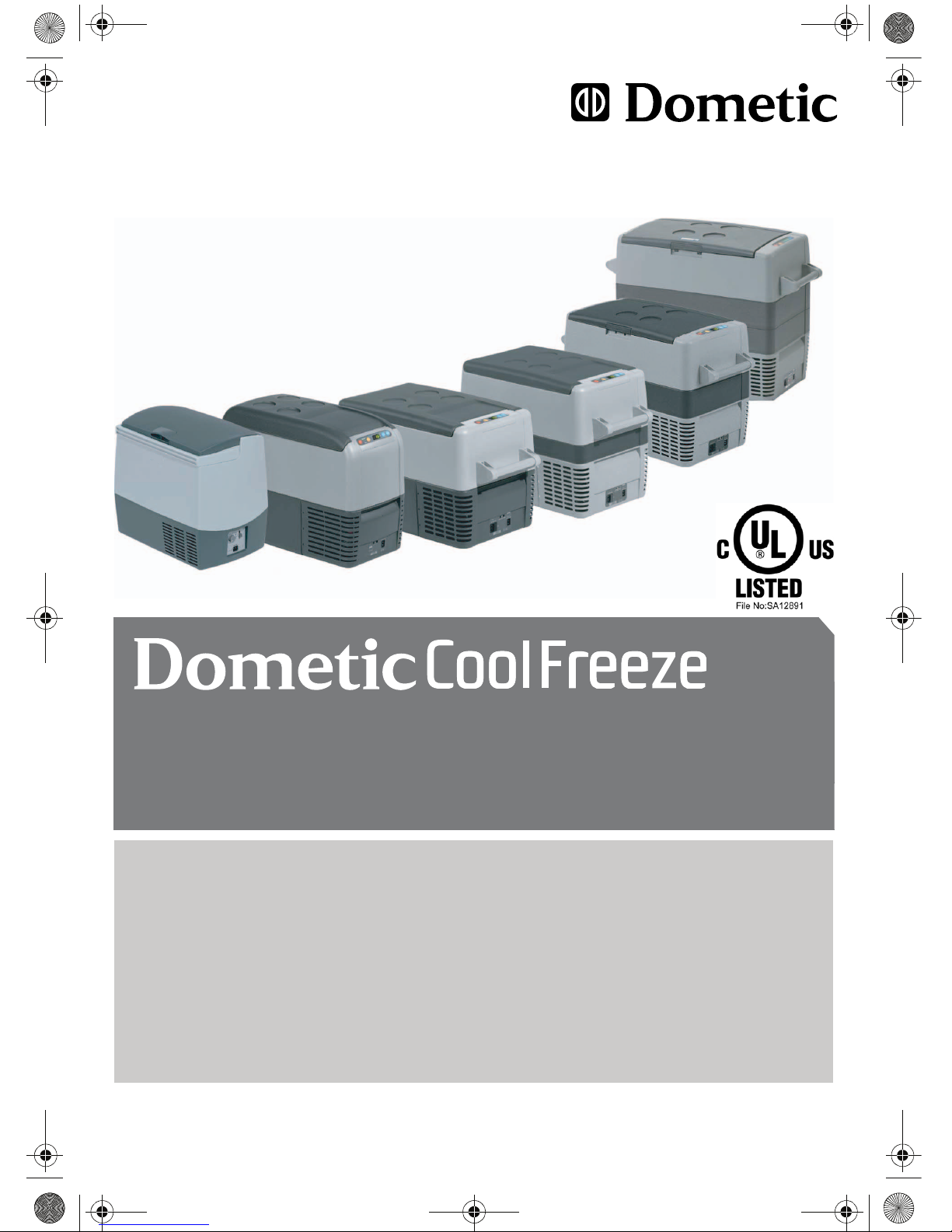
3 Scope of delivery
Fig. 1, page 3, shows the scope of delivery.
4 Intended use
The cooler is suitable for cooling and freezing foods. The device is
also suitable for use on boats.
The device is designed to be operated from a 12 V
DC
or 24 VDC
on-board supply socket of a vehicle (e. g. cigarette lighter), boat or
caravan as well as from a 120 VAC mains (for CF-18 and CF-25
only with the accessory to 220–240 VAC).
a
Caution – When cooling perishable medicines!
If you wish to cool medicines, please check if the cooling capacity
of the device is adequate for this purpose.
Item Quantity Description
11Cooler
2 1 Connection cable for 12/24 VDC connection
31
Only CF-35, CF-40, CF-50, CF-60
Connection cable for 120 V
AC
connection
4 2
Only CF-35, CF-40, CF-50, CF-60
Carrying handle, consisting of:
– 2 holders
– 1 handle
– 4 fastening screws
– 1 Operating manual
_CF-18_60.book Seite 31 Donnerstag, 26. Juli 2007 3:18 15
10
Page 11
Function description
5 Function description
The cooler can chill products, keep them cool as well as freeze
them. A maintenance-free, CFC-free refrigerant circuit with
compressor provides the cooling. The extra strong CFC-free
insulation and powerful compressor ensure especially fast cooling.
The cooler is designed for mobile use and can be carried by using
a folding carrying bracket (CF-18), two recessed grips (CF-25) or
two removable carrying handles (CF-35, CF-40, CF-50, CF-60).
When used on boats, the cooler can be withstand a constant heel
(inclination) of 30°.
Scope of functions:
CF-18 CF-25
CF-35, CF-40,
CF-50, CF-60
Power supply with
priority circuit for
connecting to the
AC mains
–– z
Battery monitor for
protecting the vehicle
battery
2-level 3-level
Turbo mode for rapid
cooling
– zz
Display with temperature
gauge
– zz
Temperature setting With
rotarycontrol
With two buttons in steps of 1 °C (2 °F)
Removable carrying
handles
–– z
_CF-18_60.book Seite 32 Donnerstag, 26. Juli 2007 3:18 15
11
Page 12
Function description
5.1 Operating and display elements
CF-25, CF-35, CF-40
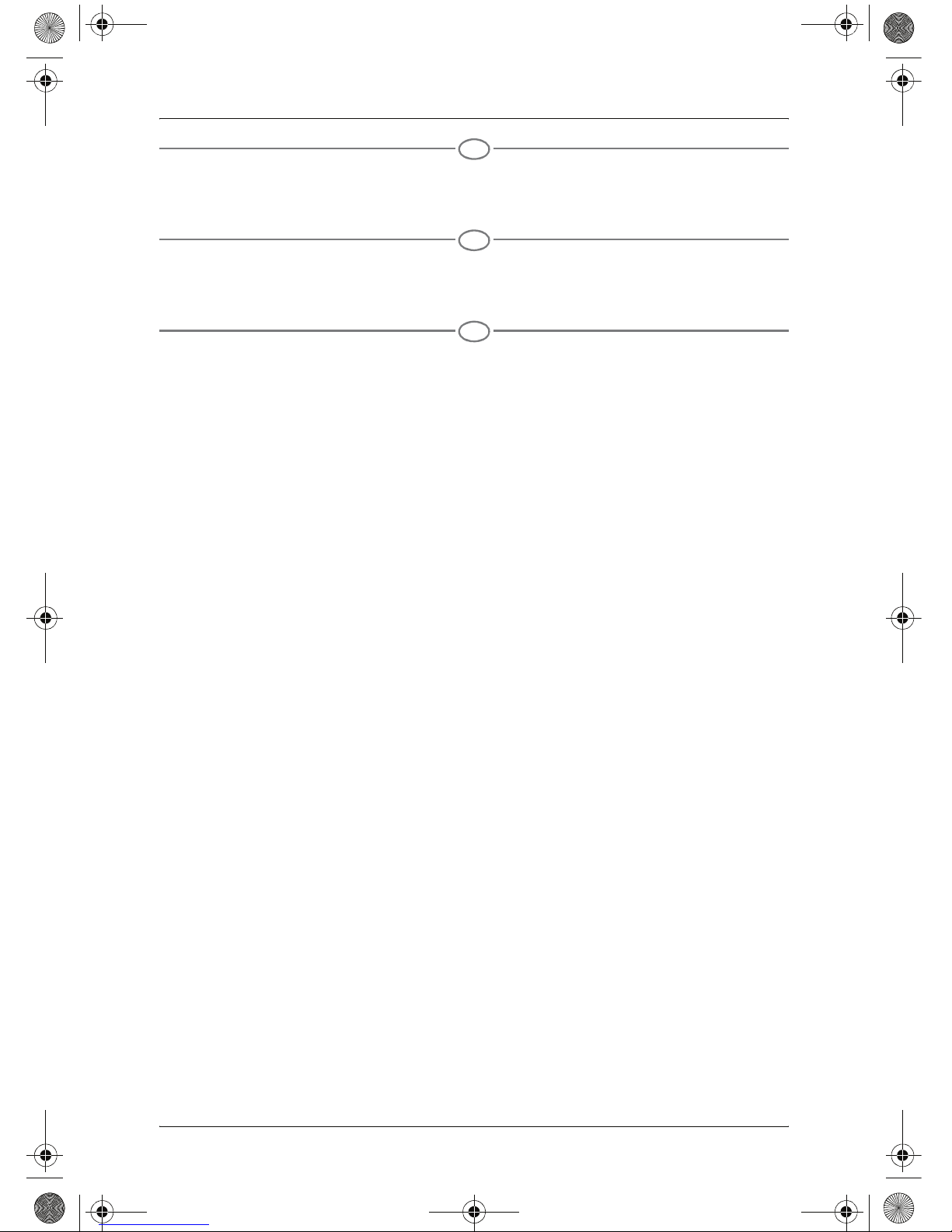
Lock for lid: Fig. 2 1, page 3
CF-18
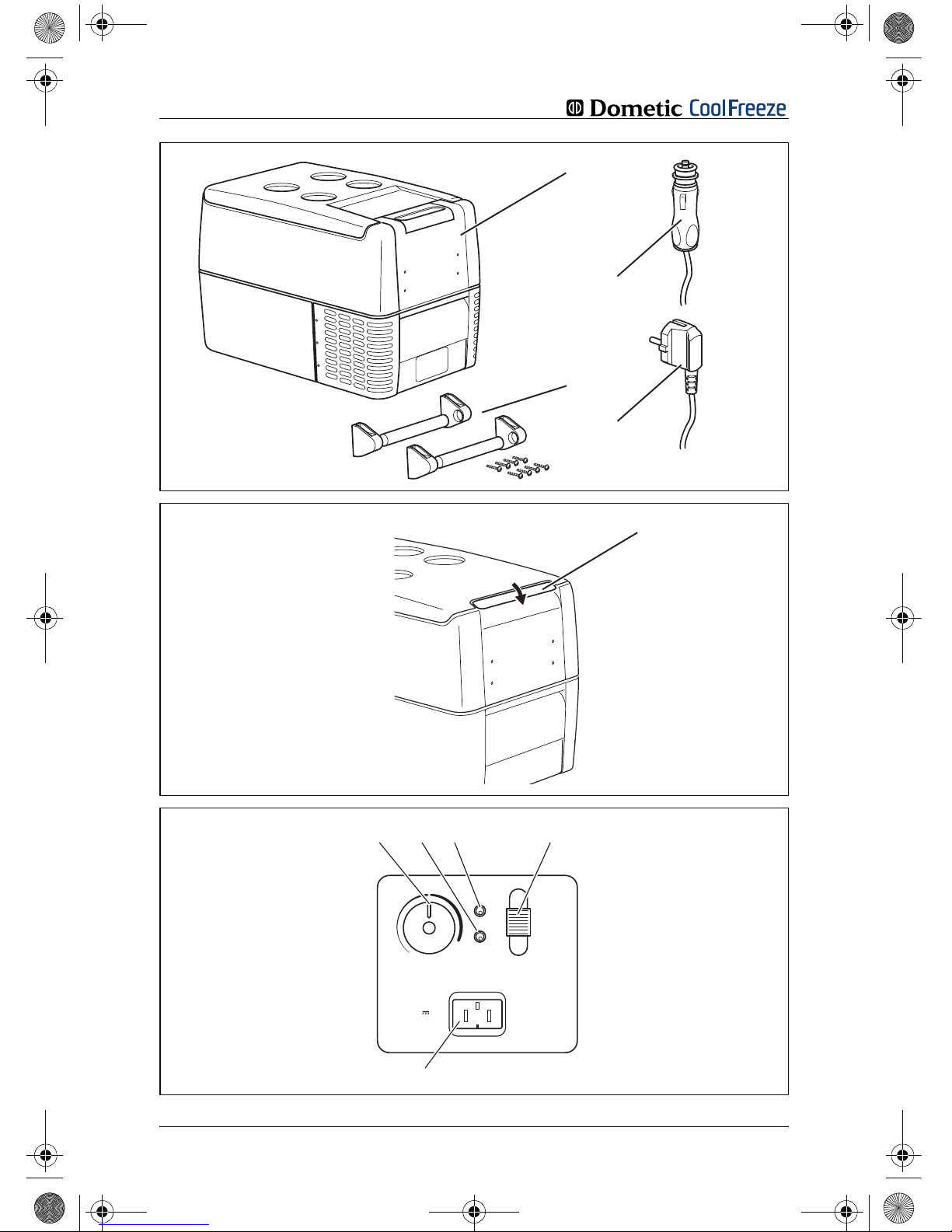
Operating panel and connection socket (Fig. 3, page 3):
Item Description Explanation
1 TEMPERATURE Temperature controller,
cooling temperature at the end positions:
COLD: +10 °C (+50 °F)
FREEZE: –18 °C (0 °F)
2 POWER Operating display
LED is lit green: Device is switched
on and ready for
operation
LED is lit yellow: Set temperature has
been reached
3 ERROR LED flashes red: Switched on device
is not ready for
operation
4 BATTERY
MONITOR
Switch-on device/battery monitor:
0: Device is switched
off
HIGH: Device is switched
on, battery monitor
is in HIGH mode
LOW: Device is switched
on, battery monitor
is in LOW mode
5 12/24V DC Connection socket DC voltage supply
_CF-18_60.book Seite 33 Donnerstag, 26. Juli 2007 3:18 15
12
Page 13
Function description
CF-25, CF-35, CF-40, CF-50, CF-60
Operating panel (Fig. 4, page 4)
CF-25
Connection sockets (Fig. 5, page 4):
CF-35, CF-40, CF-50, CF-60
Connection sockets (Fig. 6, page 4):
Item Description Explanation
1ON
OFF
Switches the cooler on or off when the
button is pressed for between one and
two seconds
2 POWER Status indication
LED lights up
green:
Compressor is on
LED lights up
orange:
Compressor is off
3 ERROR LED flashes red: Device is switched
on but not ready for
operation
4 SET Selects the input mode
- Temperature setting
- Celsius or Fahrenheit display
- Set battery monitor
5 – Display, shows the information
6 UP + Press once to increase the value
7 DOWN – Press once to decrease the value
Item Description
1 Connection socket DC voltage supply
Item Description
1 Connection socket AC voltage supply
2 Fuse holder
3 Connection socket DC voltage supply
_CF-18_60.book Seite 34 Donnerstag, 26. Juli 2007 3:18 15
13
Page 14
Operation
5.2 Accessories
If you want to operate the coolers CF-18 and CF-25 from the
220–240 V AC mains, be sure to use the rectifier DOMETIC
CoolPower EPS100.
6Operation
6.1 Before initial use
I
Note
Before starting your new cooler for the first time, you should clean
it inside and outside with a damp cloth for hygienic reasons (please
also refer to the chapter “Cleaning and maintenance” on page 43).
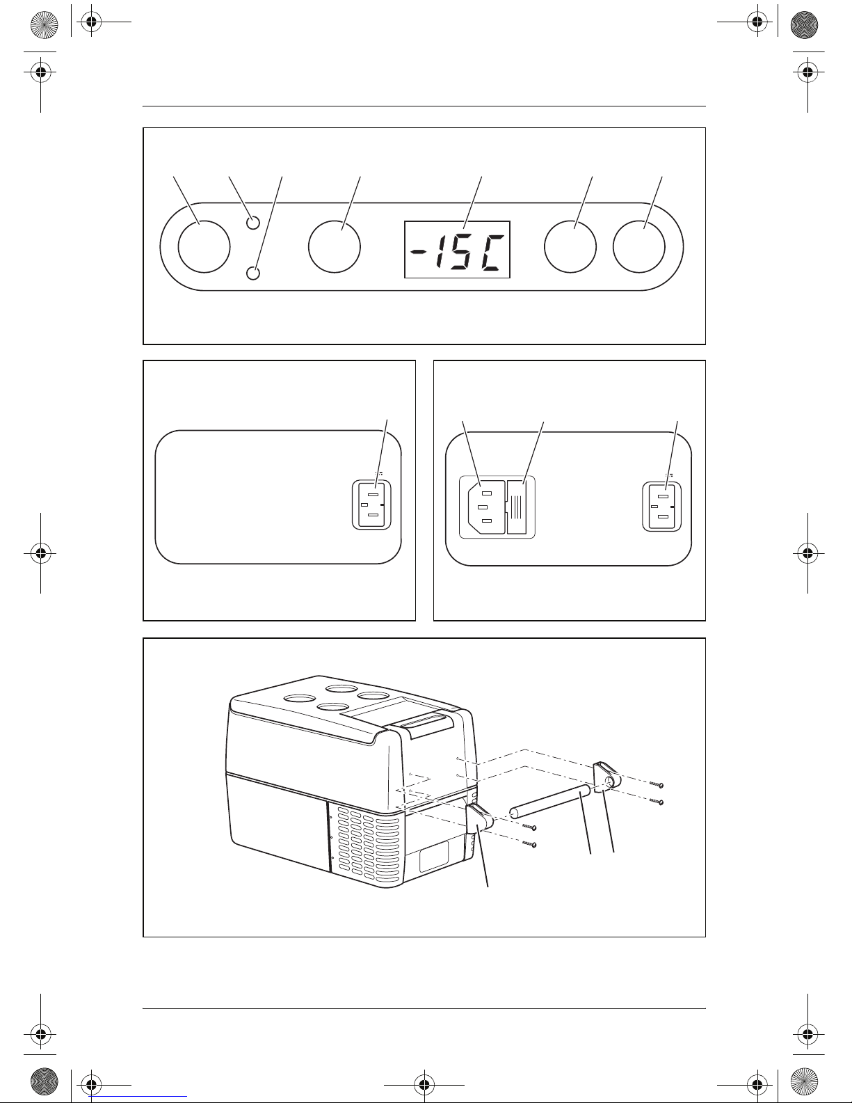
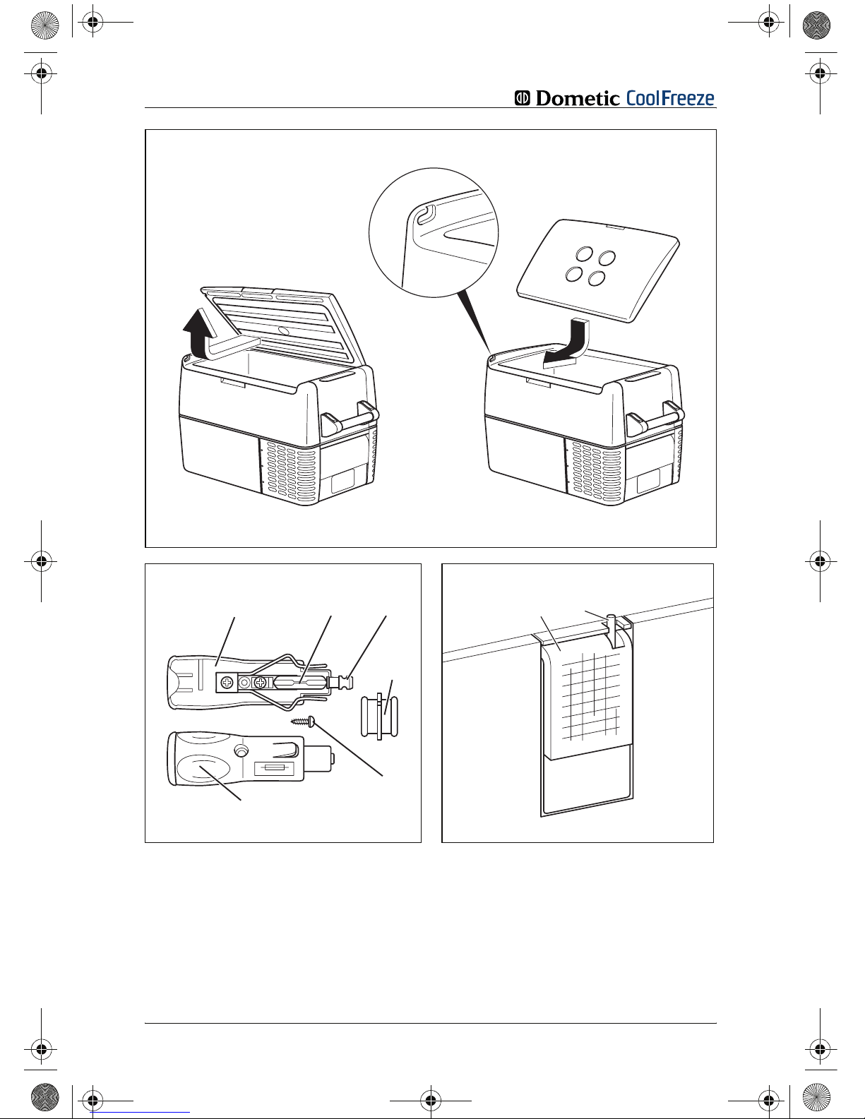
Mounting the handles
CF-35, CF-40, CF-50, CF-60
The handles are enclosed unassembled. If you wish to attach the
handles, proceed as follows:
➤ Make a handle by putting two holders (Fig. 7 1, page 4) and a
handle (Fig. 7 2, page 4) together.
➤ Fasten the grip with the enclosed screws in the holes provided.
Turning the lid stop around
CF-50, CF-60
You can turn the lid stop around if you want to open the lid from the
other side.
To do this, proceed as follows:
➤ Open the lid and pull it out (Fig. 8 A, page 5).
➤ Turn the lid.
➤ Insert the lid in the lid holders on the side opposite the cooler
(Fig. 8 B, page 5).
_CF-18_60.book Seite 35 Donnerstag, 26. Juli 2007 3:18 15
14
Page 15

Operation
Selecting the temperature units
CF-25, CF-35, CF-40, CF-50, CF-60
You can switch the temperature display between Celsius and Fahrenheit. This is how to do it:
➤ Switch on the cooler.
➤ Press the “SET” button (Fig. 4 4, page 4) twice.
➤ Use the “UP +” (Fig. 4 6, page 4) and “DOWN -” (Fig. 4 7,
page 4) buttons to select Celsius or Fahrenheit.
✓ The selected temperature units then appear in the display for a
few seconds. The display flashes several times before it returns
to the current temperature.
6.2 Energy saving tips
z Choose a well ventilated installation location which is protected
from direct sunlight.
z Allow hot food to cool down first before you place it into the
device.
z Do not open the cooler more often than necessary.
z Do not leave the lid open for longer than necessary.
z Defrost the cooler once a layer of ice forms.
z Avoid unnecessary low temperatures.
_CF-18_60.book Seite 36 Donnerstag, 26. Juli 2007 3:18 15
15
Page 16
Operation
6.3 Connecting the cooler
Connecting to a battery (Vehicle or boat)
The cooler can be operated with 12 V or 24 V DC.
e
Caution – Danger of damaging the device!
Disconnect the cooler and other consumer units from the battery
before you connect the battery to a quick charging device.
Overvoltage can damage the electronics of the device.
For safety reasons the cooler is equipped with an electronic system
to prevent the polarity reversal. This protects the cooler against
short-circuiting when connecting to a battery.
➤ Plug the 12/24-V connection cable (Fig. 1 2, page 3) into the
DC voltage socket and also into the cigarette lighter or a 12 V
or 24 V socket.
Connecting to a 120 V AC mains (E.g. in the home or office)
e
Caution – Danger of electrocution!
Never handle plugs and switches with wet hands or if you are
standing on a wet surface.
e
Caution – Danger of electrocution!
If you are operating your cooler on board a boat from a mains connection of 120 V AC, you must install a residual current circuit
breaker between the 120 V AC mains and the cooler.
Seek advice from a trained technician.
CF-35, CF-40, CF-50, CF-60
The coolers CF-35, CF-40, CF-50, CF-60 have an integrated multi-
voltage power supply with priority circuit for connecting to an AC
voltage source of 120 V. The priority circuit automatically
switches the cooler to mains operation, if the device is connected
to a 120 V AC mains, even if the 12/24 V connection cable is
still attached.
When switching between the AC mains and the battery supply,
the red LED may light up briefly.
_CF-18_60.book Seite 37 Donnerstag, 26. Juli 2007 3:18 15
16
Page 17
Operation
➤ Plug the 120 V connection cable (Fig.1 3, page 3) into
the AC voltage socket and connect it to the 120 V AC
voltage mains (only CF-35, CF-40, CF-50, CF-60).
CF-18, CF-25
To operate the coolers CF-18 and CF-25 from the 220–240 V AC
mains, use the rectifier DOMETIC CoolPower EPS100 (accessory).
6.4 Using the battery monitor
The device is equipped with a multi-level battery monitor that
protects your vehicle battery against excessive discharging when
the device is connected to the on-board 12/24 V supply.
If the cooler is operated when the vehicle ignition is switched off,
the cooler switches off automatically as soon as the supply voltage
falls below a set level. The cooler will switch back on once the
battery has been recharged to the restart voltage level.
a
Caution – Danger of damage!
When switched off by the battery monitor, the battery will no longer
be fully charged. Avoid starting repeatedly or operating current
consumers without longer charging phases. Ensure that the battery
is recharged.
In “HIGH” mode, the battery monitor responds faster than at the
levels “LOW” and “MED” (see the following table).
CF-18
CF-25, CF-35, CF-40,
CF-50, CF-60
Battery monitor mode LOW HIGH LOW MED HIGH
Switch-off voltage at 12 V
10.4 V 11.5 V 10.1 V 11.4 V 11.8 V
Restartvoltage at 12 V
11.5 V 12.5 V 11.1 V 12.2 V 12.6 V
Switch-off voltage at 24 V
22.1 V 24.0 V 21.5 V 24.1 V 24.6 V
Restart voltage at 24 V
23.6 V 25.4 V 23.0 V 25.3 V 26.2 V
_CF-18_60.book Seite 38 Donnerstag, 26. Juli 2007 3:18 15
17
Page 18
Operation
This is how to select the battery monitor mode:
CF-25, CF-35, CF-40, CF-50, CF-60
➤ Switch on the cooler.
➤ Press the “SET” button (Fig. 4 4, page 4) three times.
➤ Use the “UP +” (Fig. 4 6, page 4) and “DOWN -” (Fig. 4 7,
page 4) buttons to select the battery monitor mode.
✓ The selected mode then appears in the display for a few sec-
onds. The display flashes several times before it returns to the
current temperature.
I
Note
When the cooler is supplied by the starter battery, select the battery
monitor mode “HIGH”. If the cooler is connected to a supply battery,
the battery monitor mode “LOW” will suffice.
If you wish to operate the cooler from the AC mains, set the battery
monitor to the “LOW” position.
6.5 Using the cooler
a
Caution – Danger of overheating!
Ensure at all times that there is sufficient ventilation so that the
heat that generated during operation can dissipate. Ensure that
the ventilation slots are not covered. Make sure that the device
is sufficiently far away from walls and other objects so that the
air can circulate.
➤ Place the cooler on a firm foundation.
Make sure that the ventilation slots are not covered and that the
heated air can dissipate.
I
Note
Place the cooler as shown (Fig. 1, page 3).If you operate the box
in a different position it can be damaged.
➤ Close the cooler, see “Connecting the cooler” on page 37.
I
Note
If you wish to operate the cooler from the AC mains, set the battery
monitor to the “LOW” position.
_CF-18_60.book Seite 39 Donnerstag, 26. Juli 2007 3:18 15
18
There should be a clearance.of~150mm from the
fridge handle.
Page 19
Operation
a
Caution – Danger from excessively low temperature!
Ensure that the only those objects are placed in the cooler that are
intended to be cooled at the selected temperature.
CF-18
➤ CF-18: Slide the sliding switch (Fig. 3 4, page 3) to HIGH if
you wish to operate from a starter battery or to “LOW” if you
want to operate from a supply battery.
✓ The “POWER” LED is lit green.
✓ The cooler starts cooling the interior.
✓ When the cooling temperature has been reached, the “POWER”
LED is yellow lit.
CF-25, CF-35, CF-40, CF-50, CF-60
➤ Press the “ON/OFF” button (Fig. 4 1, page 4) for between one
and two seconds.
✓ The “POWER” LED lights up.
✓ The display (Fig. 4 5, page 4) switches on and shows the
current cooling temperature.
I
Note
The temperature displayed is that of the middle of the interior.
The temperatures elsewhere can deviate from this temperature.
✓ The cooler starts cooling the interior.
Locking the cooler
➤ Close the lid.
➤ Press the lock (Fig. 2 1, page 3) down, until it latches in
place audibly.
6.6 Setting the temperature
CF-18
➤ Set the cooling temperature with the temperature controller
(Fig. 3 1, page 3).
_CF-18_60.book Seite 40 Donnerstag, 26. Juli 2007 3:18 15
19
Page 20
Operation
CF-25, CF-35, CF-40, CF-50, CF-60
➤ Press the “SET” button (Fig. 4 4, page 4) once.
➤ Use the “UP +” (Fig. 4 6, page 4) and “DOWN -” (Fig. 4 7,
page 4) buttons to select the cooling temperature.
✓ The cooling temperature appears in the display for a few
seconds. The display flashes several times and then the current
tempera-ture is displayed again.
6.7 Switching off the cooler
➤ Empty the cooler.
➤ Switch the cooler off.
➤ Pull out the connection cable.
If you do not want to use the cooler for a longer period of time:
➤ Leave the cover slightly open. This prevents odour build-up.
6.8 Defrosting the cooler
Humidity can form frost in the interior of the cooling device or on the
vaporiser. This reduces the cooling capacity. Defrost the device in
good time to avoid this.
a
Caution – Danger of damaging the device!
Never use hard or pointed tools to remove ice or to loosen objects
which have frozen in place.
To defrost the cooler, proceed as follows:
➤ Take out the contents of the cooling device.
➤ If necessary, place them in another cooling device to keep them
cool.
➤ Switch off the device.
➤ Leave the cover open.
➤ Wipe off the defrosted water.
_CF-18_60.book Seite 41 Donnerstag, 26. Juli 2007 3:18 15
20
Page 21
Operation
6.9 Replacing the device fuse
Only CF-35, CF-40, CF-50, CF-60
e
Caution – Danger of electrocution!
Disconnect the connection cable before you replace the device
fuse.
➤ Pull off the connection cable.
➤ Pry out the fuse insert (Fig. 6 2, page 4) with a screwdriver.
➤ Replace the defective fuse with a new one that has the same
rating (T2,5AL 250V).
➤ Press the fuse insert back into the housing.
6.10 Replacing the plug fuse (12/24 V)
➤ Pull the adapter sleeve (Fig. 9 4, page 5) off of the plug.
➤ Unscrew the screw (Fig. 9 5, page 5) out of the upper half of
the housing (Fig. 9 1, page 5).
➤ Carefully raise the upper half of the housing from the lower
(Fig. 9 6, page 5) half.
➤ Take out the contact pin (Fig. 9 3, page 5).
➤ Replace the defective fuse (Fig. 9 2, page 5) with a new one
that has the same rating (8A 32V).
➤ Re-assemble the plug in the reverse order.
_CF-18_60.book Seite 42 Donnerstag, 26. Juli 2007 3:18 15
21
Page 22
Cleaning and maintenance
6.11 Replacing the light bulb
Only CF-25, CF-35, CF-40, CF-50, CF-60
➤ Press the switch pin (Fig. 0 2, page 5) downwards so that the
transparent part (Fig. 0 1, page 5) of the lamp can be removed
at the front.
➤ Replace the light bulb.
I
Note
Make sure that the polarity is correct. The side of the light bulb
marked with a plus must be placed at the contact which is connected to the red cable.
I
Note
The LEDs in the light bulb must be aligned with the transparent part
of the lamp.
➤ Press the transparent part of the lamp back into the housing.
7 Cleaning and maintenance
e
Caution – Danger of electrocution!
Always pull out the mains plug before you clean and service the device.
a
Caution – Danger of damaging the device!
Never clean the device under running water or in dish water.
Do not use abrasive cleaning agents or hard objects during cleaning as these can damage the device.
Never use brushes, scouring pads or hard or pointed tools to remove ice or to loosen objects which have frozen in place.
➤ Occasionally clean the inside of the device with a damp cloth.
_CF-18_60.book Seite 43 Donnerstag, 26. Juli 2007 3:18 15
22
Page 23

Guarantee
8Guarantee
Our general guarantee conditions apply. If the product is defective,
please send it back to the DOMETIC branch in your country
(addresses on the back of the operating manual) or to your dealer.
For repair and guarantee processing, please include the following
documents when you send in the device:
z A copy of the receipt with purchasing date
z Reason for the claim or a description of the fault
9 Troubleshooting
Fault Possible cause Suggested remedy
Device does not
function, LED does
not glow.
There is no voltage
present in the 12/24 V
socket (cigarette lighter)
in your vehicle.
The ignition must be switched on in most
vehicles to apply current to the cigarette
lighter.
No voltage present in the
AC voltage socket.
Try using another plug socket.
The device fuse is
defective.
Replace the device fuse, see “Replacing
the device fuse” on page 42.
The integrated mains
adapter is defective.
This can only be repaired by an
authorised repair centre.
The device does not
cool (plug is inserted,
“POWER” LED is lit).
Defective compressor. This can only be repaired by an
authorised customer services unit.
The device does not
cool (plug is inserted,
“ERROR” LED flashes).
Battery voltage is too
low.
Test the battery and charge it as needed.
When operating from
the 12/24-V socket
(cigarette lighter):
The ignition is on
and the device is not
working and the LED
is not lit.
Pull the plug out of the
socket and make the
following checks.
The cigarette lighter
socket is dirty. This results
in a poor electrical
contact.
If the plug of your cooler becomes very
warm in the cigarette lighter socket, either
the lighter socket must be cleaned or the
plug has not been assembled correctly.
The fuse of the 12/24 V
plug has blown.
Replace the fuse (5 A) in the cigarette
lighter plug, see “Replacing the plug fuse
(12/24 V)” on page 42.
The vehicle fuse has
blown.
Replace the vehicle’s 12/24 V socket fuse
(usually 15 A). Please refer to your
vehicle’s operating manual.
The display shows an
error message (e.g.
“Err1”) and the appliance does not cool.
The appliance has
switched off due to an
internal fault.
This can only be repaired by an
authorised repair centre.
_CF-18_60.book Seite 44 Donnerstag, 26. Juli 2007 3:18 15
23
Page 24

Disposal
10 Disposal
➤ Place the packaging material in the appropriate recycling waste
bins wherever possible.
If you wish to finally dispose of the device, ask your local recycling
centre or specialist dealer for details about how to do this in
accordance with the applicable disposal regulations.
11 Technical data
I
Note
If the ambient temperature is above +32°C (+90 °F), the minimum
temperature cannot be attained.
CF-18 CF-25 CF-35
Overall capacity: 18 litres 23 litres 31 litres
Connection voltage: 12/24 VDC 12/24 VDC and
120V
AC
Rated current:
– 12 VDC: 3.1 A 6.8 A 6.0 A
– 24 VDC: 1.9 A 3.0 A 3.0 A
– 120 V
AC
Cooling capacity: +10 °C to –18 °C (+50 °F to 0 °F)
Dimensions (WxHxD)
in mm:
465x414x300 550x425x260 580x385x360
Weight: 11.5 kg 12 kg 15 kg
CF-40 CF-50 CF-60
Overall capacity: 37 litres 49 litres 59 litres
Connection voltage: 12/24 VDC and 120 V
AC
Rated current:
– 12 VDC: 6.0 A 7.0 A 7.0 A
– 24 VDC: 3.0 A 3.0 A 3.0 A
– 120 V
AC
Cooling capacity: +10 °C to –18 °C (+50 °F to 0 °F)
Dimensions (WxHxD)
in mm:
580x445x360 630x480x360 630x582x360
Weight: 16 kg 18 kg 21.6 kg
_CF-18_60.book Seite 45 Donnerstag, 26. Juli 2007 3:18 15
24
: – – 1.3 to 0.7 A
: 1.3 to 0.7 A 1.3 to 0.7 A 1.3 to 0.7 A
Page 25

Technical data
Test/certificates:
Versions, technical modifications and delivery options reserved.
This device is CFC-free. The coolant circuit contains R134a.
– 73/23/EEC – Low Voltage Electrical Equipment
Directive
– 89/336/EEC – EMC Directive
– 95/54/EEC
_CF-18_60.book Seite 46 Donnerstag, 26. Juli 2007 3:18 15
25
Page 26

Veuillez lire ce manuel avec attention avant la mise en service puis
conservez-le. En cas de revente de l’appareil, veuillez le transmettre
au nouvel acquéreur.
Table des matières
1 Remarques concernant l’utilisation de ce manuel . . . . . . . . . 48
2 Consignes de sécurité . . . . . . . . . . . . . . . . . . . . . . . . . . . . . . . . 48
2.1 Sécurité générale . . . . . . . . . . . . . . . . . . . . . . . . . . . . . . . . 49
2.2 Consignes de sécurité concernant l’utilisation de l’appareil 50
3 Contenu de la livraison . . . . . . . . . . . . . . . . . . . . . . . . . . . . . . . 51
4 Usage conforme . . . . . . . . . . . . . . . . . . . . . . . . . . . . . . . . . . . . . 51
5 Description du fonctionnement . . . . . . . . . . . . . . . . . . . . . . . . . 52
5.1 Commandes et affichage . . . . . . . . . . . . . . . . . . . . . . . . . . 53
5.2 Accessoires . . . . . . . . . . . . . . . . . . . . . . . . . . . . . . . . . . . . 55
6 Utilisation . . . . . . . . . . . . . . . . . . . . . . . . . . . . . . . . . . . . . . . . . . . 55
6.1 Avant la première utilisation . . . . . . . . . . . . . . . . . . . . . . . . 55
6.2 Conseils pour économiser de l’énergie . . . . . . . . . . . . . . . . 56
6.3 Raccordement de la glacière . . . . . . . . . . . . . . . . . . . . . . . 57
6.4 Utilisation du protecteur de batterie . . . . . . . . . . . . . . . . . . 58
6.5 Utilisation de la glacière . . . . . . . . . . . . . . . . . . . . . . . . . . . 60
6.6 Réglage de la température . . . . . . . . . . . . . . . . . . . . . . . . . 61
6.7 Mise hors-service de la glacière . . . . . . . . . . . . . . . . . . . . . 62
6.8 Dégivrage de la glacière . . . . . . . . . . . . . . . . . . . . . . . . . . . 62
6.9 Remplacement du fusible de l’appareil . . . . . . . . . . . . . . . . 63
6.10 Remplacement du fusible du connecteur (12/24 V) . . . . . . 63
6.11 Changer les éléments lumineux . . . . . . . . . . . . . . . . . . . . . 64
7 Nettoyage et entretien . . . . . . . . . . . . . . . . . . . . . . . . . . . . . . . . 64
8 Garantie . . . . . . . . . . . . . . . . . . . . . . . . . . . . . . . . . . . . . . . . . . . . 65
9 Dépannage . . . . . . . . . . . . . . . . . . . . . . . . . . . . . . . . . . . . . . . . . . 65
10 Retraitement . . . . . . . . . . . . . . . . . . . . . . . . . . . . . . . . . . . . . . . . 66
11 Caractéristiques techniques . . . . . . . . . . . . . . . . . . . . . . . . . . . 67
_CF-18_60.book Seite 47 Donnerstag, 26. Juli 2007 3:18 15
26
Page 27

Remarques concernant l’utilisation de ce manuel
1 Remarques concernant l’utilisation de
ce manuel
Les symboles suivants sont utilisés dans ce manuel :
a
Attention !
Consigne de sécurité : le non-respect de ces consignes peut cau-
ser des dommages matériels ou compromettre la sécurité des personnes.
e
Attention !
Consigne de sécurité indiquant un danger lié à un courant électri-
que ou à une tension électrique : le non-respect de ces consignes
peut causer des dommages matériels ou compromettre la sécurité
des personnes, et nuire au fonctionnement de l’appareil.
I
Remarque
Informations complémentaires sur l’utilisation de l’appareil.
➤ Manipulation : ce symbole vous indique une action à effectuer.
Les manipulations à effectuer sont décrites étape par étape.
✓ Ce symbole décrit le résultat d’une manipulation.
Fig. 2 1, page 3 : cette donnée vous indique un élément dans une
illustration, dans cet exemple la « position 1 de la figure 2 àla
page 3 ».
Respectez également les consignes de sécurité suivantes.
2 Consignes de sécurité
a
z Attention !
DOMETIC International décline toute responsabilité en cas de
dommages causés par :
– des influences mécaniques et des surtensions ayant endom-
magé le matériel,
– des modifications apportées à l’appareil sans autorisation
explicite de la part de DOMETIC International,
– une utilisation différente de celle décrite dans le manuel.
_CF-18_60.book Seite 48 Donnerstag, 26. Juli 2007 3:18 15
27
Page 28

Consignes de sécurité
2.1 Sécurité générale
e
z Attention – Danger de mort par électrocution !
En cas d’utilisation sur des bateaux : veillez à ce que votre alimentation électrique soit sécurisée par un disjoncteur différentiel si l’appareil est branché sur secteur !
z Comparez la tension indiquée sur la plaque signalétique avec
l’alimentation électrique dont vous disposez.
z Branchez l’appareil uniquement comme indiqué ci-dessous :
– avec le câble de raccordement fourni (fig. 1 2, page 3) sur
l’allume-cigares ou la prise 12/24 V du véhicule
– ou avec le câble de raccordement fourni (fig. 1 3, page 3)
sur secteur à courant alternatif 120 V (uniquement
pour CF-35, CF-40, CF-50, CF-60).
z Si le câble de raccordement est endommagé, il doit être rempla-
cé par un câble spécial que vous pouvez commander chez le fabricant ou un représentant du service après-vente.
z Ne débranchez jamais l’appareil de l’allume-cigares ou de la pri-
se en tirant directement sur le câble de raccordement.
z Débranchez le câble de raccordement
– avant tout nettoyage et entretien
– après chaque utilisation
– avant un changement de fusible
z Débranchez l’appareil et les autres consommateurs d’énergie
de la batterie avant de recharger la batterie avec un chargeur
rapide. Les surtensions peuvent endommager l’électronique
des appareils.
a
z Les appareils électriques ne sont pas des jouets pour en-
fants !
Placez et utilisez l’appareil hors de la portée des enfants.
z Si l’appareil présente des dégâts visibles, il est interdit de le
mettre en service.
z Seul un personnel qualifié est habilité à effectuer des répara-
tions sur l’appareil. Toute réparation mal effectuée risque d’entraîner de sérieux dangers.
Pour toute réparation, adressez-vous au service après-vente
DOMETIC.
z Ne jamais ouvrir le circuit de refroidissement !
_CF-18_60.book Seite 49 Donnerstag, 26. Juli 2007 3:18 15
28
Page 29

Consignes de sécurité
z Ne pas utiliser la glacière pour le transport de produits corrosifs
ou de solvants !
z Les produits alimentaires doivent être conservés dans leurs em-
ballages originaux ou dans des récipients appropriés.
2.2 Consignes de sécurité concernant l’utilisation
de l’appareil
e
z Attention – Danger de mort par électrocution !
Ne touchez jamais de lignes électriques dénudées à mains
nues. Cela est surtout valable en cas de fonctionnement sur
secteur.
z Avant de mettre l’appareil en service, assurez-vous que la ligne
d’alimentation électrique et la fiche sont sèches.
a
z Il est interdit d’utiliser un appareil électrique à l’intérieur de la
glacière.
z Installez l’appareil dans un endroit sec et à l’abri des éclabous-
sures d’eau.
z Tenez l’appareil et les câbles à l’abri de la pluie et de l’humidité.
z Ne placez pas l’appareil près de flammes ou d’autres sources
de chaleur (chauffage, rayons solaires, fours à gaz, etc.).
z Attention, danger de surchauffe !
Veillez toujours à ce que la chaleur produite lors du fonctionnement
soit suffisamment dissipée. Assurez-vous que les fentes d’aération
ne sont pas recouvertes. Veillez à ce que l’appareil se trouve à distance suffisante des murs ou des objets, de sorte que l’air puisse
circuler.
z Ne plongez jamais l’appareil dans l’eau.
z Ne remplissez pas le bac intérieur de substances liquides ou
de glace.
_CF-18_60.book Seite 50 Donnerstag, 26. Juli 2007 3:18 15
29
Page 30

Contenu de la livraison
3 Contenu de la livraison
La fig. 1, page 3, indique les pièces comprises dans la livraison.
4 Usage conforme
La glacière est conçue pour la réfrigération et la congélation de
produits alimentaires. L’appareil peut également être utilisé sur
des bateaux.
L’appareil peut être branché sur la prise d’alimentation 12 VCC
ou 24 VCC d’un véhicule (par ex. un allume-cigare), d’un bateau
ou d’un camping-car, ou être raccordé à un réseau à tension
alternative de 120 VCA (pour CF-18 et CF-25, l’accessoire
pour 220–240 VCA est nécessaire).
a
Attention – Prenez garde aux médicaments périssables !
Si vous souhaitez conserver au frais des médicaments, nous vous
prions de vérifier si la puissance frigorifique de l’appareil correspond à la température de conservation recommandée pour les médicaments concernés.
N° Quantité Désignation
11Glacière
2 1 Câble de raccordement pour prise 12/24 V
CC
31
Uniquement pour CF-35, CF-40, CF-50,
CF-60
Câble de raccordement pour prise
120 V
CA
4 2
Uniquement pour CF-35, CF-40, CF-50,
CF-60
Poignée de transport, composée de :
– 2 fixations
– 1 corps de poignée
– 4 vis de fixation
– 1 Manuel d’utilisation
_CF-18_60.book Seite 51 Donnerstag, 26. Juli 2007 3:18 15
30
Page 31

Description du fonctionnement
5 Description du fonctionnement
La glacière permet de réfrigérer, de tenir au frais ou de congeler
des produits. La réfrigération est assurée par un circuit de
refroidissement à compresseur qui fonctionne sans CFC et
ne nécessite aucune maintenance. Sa puissante isolation
sans CFC et son compresseur performant garantissent un
refroidissement particulièrement rapide.
La glacière est particulièrement adaptée à une utilisation mobile,
et peut être transportée à l’aide d’une poignée repliable (CF-18),
deux poignées encastrées (CF-25) ou deux poignées (dé)montables
(CF-35, CF-40, CF-50, CF-60).
En cas d’utilisation sur bateaux, la glacière peut supporter un angle
de gîte permanent de 30°.
Fonctions de l’appareil :
CF-18 CF-25
CF-35, CF-40,
CF-50, CF-60
Bloc d’alimentation
avec raccordement
prioritaire pour
branchement sur une
tension alternative
–– z
Protecteur de batterie
pour protéger la batterie
du véhicule
2
niveaux
3 niveaux
Mode turbo pour un
refroidissement plus
rapide
– zz
Ecran avec affichage de
la température
– zz
Réglage de la
température
par
bouton
rotatif
avec deux touches, par pas de 1 °C (2 °F)
Poignées de transport
montables
–– z
_CF-18_60.book Seite 52 Donnerstag, 26. Juli 2007 3:18 15
31
Page 32

Description du fonctionnement
5.1 Commandes et affichage
CF-25, CF-35, CF-40
Verrouillage du couvercle : fig. 2 1, page 3
CF-18
Panneau de commande et prise de raccordement
(fig. 3, page 3) :
N° Désignation Signification
1 TEMPERATURE Régulateur de température,
température de refroidissement
minimale et maximale :
COLD : +10 °C (+50 °F)
FREEZE : –18 °C (0 °F)
2 POWER Témoin lumineux de fonctionnement
La DEL s’allume
en vert :
l’appareil est allumé
et prêt à fonctionner
La DEL s’allume
en jaune :
la température
réglée est atteinte
3 ERROR La DEL clignote
en rouge :
l’appareil est allumé
mais n’est pas prêt
à fonctionner
4 BATTERY
MONITOR
Commutateur / protecteur de batterie :
0: l’appareil est éteint
HIGH : l’appareil est allumé,
le protecteur de
batterie est en
mode HIGH
LOW : l’appareil est allumé,
le protecteur de
batterie est en
mode LOW
5 12/24V DC Prise de raccordement de l’alimentation
en tension continue
_CF-18_60.book Seite 53 Donnerstag, 26. Juli 2007 3:18 15
32
Page 33

Description du fonctionnement
CF-25, CF-35, CF-40, CF-50, CF-60
Panneau de commande (fig. 4, page 4)
CF-25
Prises de raccordement (fig. 5, page 4) :
Pos. Désignation Signification
1ON
OFF
Permet d’allumer ou d’éteindre la glacière sur une pression d’une à deux
seconde sur la touche
2 POWER Témoin lumineux de fonctionnement
La DEL s’allume
en vert :
le compresseur est
en marche
La DEL s’allume
en orange :
le compresseur est
arrêté
3 ERROR La DEL clignote
en rouge :
l’appareil est allumé
mais n’est pas prêt
à fonctionner
4 SET Permet de sélectionner le mode de saisie
- Réglage de la température
- Indication de degrés Celsius
ou Fahrenheit
- Réglage du protecteur de batterie
5 – Ecran, affiche les valeurs
6 UP + Une pression sur cette touche augmente
la valeur de saisie sélectionnée
7 DOWN – Une pression sur cette touche diminue la
valeur de saisie sélectionnée
N° Désignation
1 Prise de raccordement de l’alimentation en tension continue
_CF-18_60.book Seite 54 Donnerstag, 26. Juli 2007 3:18 15
33
Page 34

Utilisation
CF-35, CF-40, CF-50, CF-60
Prises de raccordement (fig. 6, page 4) :
5.2 Accessoires
Si vous désirez alimenter les glacières CF-18 et CF-25 sur un
réseau à tension alternative de 220–240 V, utilisez le redresseur
DOMETIC CoolPower EPS100.
6 Utilisation
6.1 Avant la première utilisation
I
Remarque
Avant de mettre en service votre nouvelle glacière, vous devez,
pour des raisons d’hygiène, la nettoyer à l’intérieur et à l’extérieur
à l’aide d’un tissu humide (voir aussi chapitre « Nettoyage et
entretien », page 64).
Monter les poignées
CF-35, CF-40, CF-50, CF-60
Les poignées sont fournies démontées. Pour monter les poignées,
procédez de la manière suivante :
➤ Assemblez deux fixations (fig. 7 1, page 4) avec un corps de
poignée (fig. 7 2, page 4) pour former une poignée.
➤ Vissez la poignée ainsi constituée dans les orifices prévus à
l’aide des vis fournies.
N° Désignation
1 Prise de raccordement de l’alimentation en tension alternative
2 Porte-fusible
3 Prise de raccordement de l’alimentation en tension continue
_CF-18_60.book Seite 55 Donnerstag, 26. Juli 2007 3:18 15
34
Page 35

Utilisation
Retournement de la butée du couvercle
CF-50, CF-60
Vous pouvez retourner la butée du couvercle si vous voulez ouvrir
celui-ci par l'autre côté. Procédez comme suit :
➤ Ouvrez le couvercle et retirez-le (fig. 8 A, page 5).
➤ Tournez le couvercle.
➤ Placez le couvercle dans l'emplacement du couvercle situé du
côté opposé de la glacière (fig. 8 B, page 5).
Sélection de l’unité de température
CF-25, CF-35, CF-40, CF-50, CF-60
Vous pouvez sélectionner l’affichage de la température en degrés
Celsius ou Fahrenheit. Procédez comme suit :
➤ Allumez la glacière.
➤ Appuyez deux fois sur la touche « SET » (fig. 4 4, page 4).
➤ Sélectionnez l’unité de température (Celsius ou Fahrenheit) à
l’aide des touches « UP + » (fig. 4 6, page 4) ou « DOWN - »
(fig. 4 7, page 4).
✓ L’écran affiche l’unité de température sélectionnée pendant
quelques secondes. L’écran clignote plusieurs fois avant de revenir à l'affichage de la température actuelle.
6.2 Conseils pour économiser de l’énergie
z Choisissez un emplacement bien aéré et à l’abri du soleil.
z Laissez refroidir les aliments chauds avant de les mettre dans
la glacière.
z N’ouvrez pas la glacière plus souvent que nécessaire.
z Ne laissez pas le couvercle ouvert plus longtemps que
nécessaire.
z Dégivrez la glacière dès qu’une couche de glace s’est formée.
z Evitez une température intérieure inutilement basse.
_CF-18_60.book Seite 56 Donnerstag, 26. Juli 2007 3:18 15
35
Page 36

Utilisation
6.3 Raccordement de la glacière
Raccordement à une batterie (automobile ou bateau)
La glacière peut être branchée sur une tension continue de 12 V ou
de 24 V.
e
Attention – L’appareil peut être endommagé !
Débranchez la glacière et les autres consommateurs d’énergie de
la batterie avant de recharger la batterie avec un chargeur rapide.
Les surtensions peuvent endommager l’électronique des appareils.
Pour des raisons de sécurité, la glacière est équipée d’une
protection électronique contre les inversions de polarité en
cas de raccordement à une batterie et contre les court-circuits.
➤ Branchez le câble de raccordement 12/24 V (fig. 1 2, page 3)
dans la prise pour tension continue et raccordez-le à l’allumecigares ou à une prise 12 ou 24 V.
Raccordement à un réseau à tension alternative de 120 V (p. ex. à
la maison ou au bureau)
e
Attention – Danger de mort par électrocution !
Ne vous approchez pas de prises ou de commutateurs lorsque
vous avez les mains mouillées ou les pieds dans l’eau.
e
Attention – Danger de mort par électrocution !
Si vous raccordez votre glacière à bord d’un bateau à un réseau
àtension alternative 120 V l’intermédiaire d’une prise de quai,
vous devez absolument brancher un disjoncteur différentiel entre le
réseau 120 V et la glacière.
Veuillez vous renseigner auprès d’un spécialiste.
_CF-18_60.book Seite 57 Donnerstag, 26. Juli 2007 3:18 15
36
Page 37

Utilisation
CF-35, CF-40, CF-50, CF-60
Les glacières CF-35, CF-40, CF-50, CF-60 sont équipées d’un
bloc d’alimentation intégré avec raccordement prioritaire pour
branchement sur une tension alternative de 120V. Il permet
de passer directement en fonctionnement sur secteur quand
l’appareil est raccordé à un réseau de courant alternatif 120 V,
même si le câble de raccordement 12 V ou 24 V est encore
branché.
Lors du basculement entre alimentation sur réseau à courant
alternatif et sur batterie, la DEL rouge peut s’allumer pendant
quelques minutes.
➤ Branchez le cable de raccordement 120 V (fig.1 3,
page 3) sur la prise pour tension alternative et raccordez-le
ausecteur à courant alternatif 120 V (uniquement pour
CF-35, CF-40, CF-50, CF-60).
CF-18, CF-25
Si vous désirez alimenter les glacières CF-18 et CF-25 sur un
réseau à tension alternative de 220–240 V, utilisez le redresseur
DOMETIC CoolPower EPS100 (accessoire).
6.4 Utilisation du protecteur de batterie
L’appareil est équipé d’un protecteur de batterie qui protège
la batterie de votre véhicule, afin qu’elle ne se décharge pas
excessivement lorsque la glacière est raccordée au réseau
12/24 V du véhicule.
Si la glacière est mise en service alors que l’allumage du véhicule
est éteint, elle s’éteint automatiquement dès que la tension
d’alimentation descend en dessous d’une valeur réglable. La
glacière se rallume dès que la batterie est rechargée et que la
tension de rallumage est atteinte.
a
Attention – Risque d’endommagement !
Au moment de l’arrêt par le protecteur de batterie, la batterie ne
possède plus toute sa capacité de charge ; évitez les démarrages
répétés ou la mise en marche de consommateurs d’énergie,
tant que la batterie n’a pas été rechargée. Veillez à recharger
la batterie.
_CF-18_60.book Seite 58 Donnerstag, 26. Juli 2007 3:18 15
37
Page 38

Utilisation
En mode « HIGH », le protecteur de batterie se met en marche plus
rapidement qu’en mode « LOW » ou « MED » (voir tableau
suivant).
Pour modifier le mode du protecteur de batterie, procédez comme
suit :
CF-25, CF-35, CF-40, CF-50, CF-60
➤ Allumez la glacière.
➤ Appuyez trois fois sur la touche « SET » (fig. 4 4, page 4).
➤ Sélectionnez le mode du protecteur de batterie à l’aide des tou-
ches « UP + » (fig. 4 6, page 4) ou « DOWN - » (fig. 4 7,
page 4).
✓ L’écran affiche le mode sélectionné pendant quelques secon-
des. L’écran clignote plusieurs fois avant de revenir à l’affichage
de la température actuelle.
I
Remarque
Lorsque la glacière est alimentée par la batterie de démarrage, réglez le protecteur de batterie sur le mode « HIGH ». Lorsque la glacière est raccordée à une batterie d’alimentation, le mode « LOW »
suffit.
Lorsque vous voulez faire fonctionner la glacière sur le réseau à
tension alternative, réglez le protecteur de batterie sur le mode
«LOW».
CF-18
CF-25, CF-35, CF-40,
CF-50, CF-60
Mode protecteur de
batterie
LOW HIGH LOW MED HIGH
Tension d’arrêt pour 12 V
10,4 V 11,5 V 10,1 V 11,4 V 11,8 V
Tension de rallumage
pour 12 V
11,5 V 12,5 V 11,1 V 12,2 V 12,6 V
Tension d’arrêt pour 24 V
22,1 V 24,0 V 21,5 V 24,1 V 24,6 V
Tension de rallumage
pour 24 V
23,6 V 25,4 V 23,0 V 25,3 V 26,2 V
_CF-18_60.book Seite 59 Donnerstag, 26. Juli 2007 3:18 15
38
Page 39

Utilisation
6.5 Utilisation de la glacière
a
Attention – danger de surchauffe !
Veillez toujours à ce que la chaleur produite lors du fonctionnement
puisse se dissiper suffisamment. Assurez-vous que les fentes
d’aération ne sont pas recouvertes. Veillez à ce que l’appareil se
trouve à distance suffisante des murs ou des objets, de sorte que
l’air puisse circuler.
➤ Placez la glacière sur une surface stable.
Veillez à ce que les fentes d’aération ne soient pas recouvertes,
afin que l’air chaud puisse bien s’évacuer.
I
Remarque
Montez la glacière comme indiqué sur l'illustration (voir fig.). Si la
glacière est utilisée dans une autre position, elle risque d'être endommagée.
➤ Raccordez la glacière (voir « Raccordement de la glacière »,
page 57).
I
Remarque
Lorsque vous voulez faire fonctionner la glacière sur le réseau à
tension alternative, réglez le protecteur de batterie sur le mode
«LOW».
a
Attention – Risque de températures trop basses !
Veillez à ne déposer dans la glacière que des objets ou des aliments qui peuvent être réfrigérés à la température sélectionnée.
CF-18
➤ CF-18: Placez l’interrupteur à coulisse (fig. 3 4, page 3) en
position « HIGH » pour fonctionner sur une batterie de démarrage,
ou sur « LOW » pour fonctionner sur une batterie d’alimentation.
✓ La DEL « POWER » s’allume en vert.
✓ La glacière commence par la réfrigération du compartiment
intérieur.
✓ Lorsque la température de refroidissement réglée est atteinte,
la DEL « POWER » s’allume en jaune.
_CF-18_60.book Seite 60 Donnerstag, 26. Juli 2007 3:18 15
39
espace~150mm.de glacière.
Page 40

Utilisation
CF-25, CF-35, CF-40, CF-50, CF-60
➤ Appuyez pendant une à deux secondes sur la touche « ON/OFF »
(fig. 4 1, page 4).
✓ La DEL « POWER » s’allume.
✓ L’écran (fig. 4 5, page 4) s’allume et indique la température
actuelle.
I
Remarque
La température affichée est celle du centre du compartiment intérieur. Il est possible que la température varie selon la position.
✓ La glacière commence par la réfrigération du compartiment
intérieur.
Verrouiller la glacière
➤ Fermez le couvercle.
➤ Abaissez le verrouillage (fig. 2 1, page 3) jusqu'à ce qu'il
s'enclenche audiblement.
6.6 Réglage de la température
CF-18
➤ Réglez la température de refroidissement à l’aide du régulateur
de température (fig. 3 1, page 3).
CF-25, CF-35, CF-40, CF-50, CF-60
➤ Appuyez une fois sur la touche « SET » (fig. 4 4, page 4).
➤ Sélectionnez la température de refroidissement à l’aide des tou-
ches « UP + » (fig. 4 6, page 4) ou « DOWN - » (fig. 4 7,
page 4).
✓ L’affichage indique pendant quelques secondes la température
de refroidissement réglée. L'écran clignote plusieurs fois avant
de revenir à l'affichage de la température actuelle.
_CF-18_60.book Seite 61 Donnerstag, 26. Juli 2007 3:18 15
40
Page 41

Utilisation
6.7 Mise hors-service de la glacière
➤ Videz la glacière.
➤ Eteignez la glacière.
➤ Débranchez le câble de raccordement.
Lorsque vous ne voulez pas utiliser la glacière pendant une période
prolongée :
➤ Laissez le couvercle légèrement ouvert. Vous évitez ainsi la
formation d’odeurs.
6.8 Dégivrage de la glacière
L’humidité de l’air peut se condenser sous forme de givre au niveau
de l’évaporateur ou à l’intérieur de la glacière et diminuer ainsi sa
puissance frigorifique. Veillez donc à dégivrer l’appareil à temps.
a
Attention – L’appareil peut être endommagé !
N’utilisez jamais d’outils durs ou pointus pour enlever les couches
de glace ou pour détacher des objets pris dans le givre.
Procédez de la manière suivante pour dégivrer la glacière :
➤ Retirez les aliments.
➤ Placez-les éventuellement dans un autre réfrigérateur,
pour qu’ils restent froids.
➤ Eteignez l’appareil.
➤ Laissez le couvercle ouvert.
➤ Essuyez l’eau provenant du dégivrage.
_CF-18_60.book Seite 62 Donnerstag, 26. Juli 2007 3:18 15
41
Page 42

Utilisation
6.9 Remplacement du fusible de l’appareil
Uniquement pour CF-25, CF-35, CF-40, CF-50, CF-60
e
Attention – Danger de mort par électrocution !
Avant de remplacer le fusible, retirez les câbles de raccordement.
➤ Débranchez les câbles de raccordement.
➤ Retirez le porte-fusible (fig. 6 2, page 4) en faisant par ex.
levier avec un tournevis.
➤ Remplacez le fusible défectueux par un nouveau fusible de
même valeur (T2,5AL 250V).
➤ Replacez le porte-fusible dans le boîtier, en appuyant dessus.
6.10 Remplacement du fusible du connecteur (12/24 V)
➤ Dévissez le compensateur (fig. 9 4, page 5) du connecteur.
➤ Retirez la vis (fig. 9 5, page 5) de la partie supérieure du
boîtier (fig. 9 1, page 5).
➤ Soulevez avec précaution la partie supérieure du boîtier pour la
séparer de la partie inférieure (fig. 9 6, page 5).
➤ Retirez la fiche de contact (fig. 9 3, page 5).
➤ Remplacez le fusible défectueux (fig. 9 2, page 5) par un
nouveau fusible de même valeur (8A 32V).
➤ Remontez le connecteur en effectuant les opérations dans
l’ordre inverse.
_CF-18_60.book Seite 63 Donnerstag, 26. Juli 2007 3:18 15
42
Page 43

Nettoyage et entretien
6.11 Changer les éléments lumineux
Uniquement pour CF-25, CF-35, CF-40, CF-50, CF-60
➤ Appuyez sur la tige de contact (fig. 0 2, page 5) pour que la
partie transparente (fig. 0 1, page 5) de la lampe puisse être
retirée par devant.
➤ Remplacez l'élément lumineux.
I
Remarque
Tenez compte de la polarité ! Le côté de l'élément lumineux désigné par le plus doit être placé au niveau du contact relié à la ligne
rouge.
I
Remarque
Les DEL de l'élément lumineux doivent être orientées vers la partie
transparente de la lampe.
➤ Replacez la partie transparente de la lampe dans le boîtier.
7 Nettoyage et entretien
e
Attention – Danger de mort par électrocution !
Avant tout nettoyage et entretien, débranchez la prise secteur.
a
Attention – L’appareil peut être endommagé !
Ne nettoyez jamais l’appareil à l’eau courante et ne le plongez pas
non plus dans l’eau.
N’utilisez pas de produits de lavage abrasifs ou d’objets durs pour
le nettoyage, car ceux-ci pourraient endommager l’appareil.
N’utilisez jamais de brosses, d’éponges abrasives ou d’outils durs
ou pointus pour enlever les couches de glace ou pour détacher des
objets pris dans le givre.
➤ Nettoyez l’appareil avec un tissu humide.
_CF-18_60.book Seite 64 Donnerstag, 26. Juli 2007 3:18 15
43
Page 44

Garantie
8 Garantie
Nos conditions générales de garantie s’appliquent à ce produit.
Veuillez envoyer le produit à la succursale DOMETIC de votre pays
(voir verso de ce manuel d’utilisation pour les adresses) ou à votre
revendeur spécialisé. Veuillez y joindre les documents suivants
pour la gestion des réparations et de la garantie :
z Une copie de la facture datée
z Le motif de la réclamation ou une description du
dysfonctionnement.
9 Dépannage
Dysfonctionnement Cause éventuelle Solution proposée
L’appareil ne fonctionne
pas, la DEL n’est pas
allumée.
La prise 12/24 volts
(allume-cigares) de
votre véhicule n’est
pas sous tension.
Dans la plupart des véhicules, le contact
doit être mis pour que l’allume-cigares soit
sous tension.
La prise de tension
alternative n’est pas
sous tension.
Essayez sur une autre prise.
Le fusible de l’appareil
est défectueux.
Remplacez le fusible de l’appareil
(voir « Remplacement du fusible de
l’appareil », page 63).
Le bloc d’alimentation
intégré est défectueux.
La réparation peut être effectuée
uniquement par un service après-vente
agréé.
L’appareil ne réfrigère
pas (le connecteur
est branché, la DEL
« POWER » est
allumée).
Compresseur
défectueux.
La réparation peut être effectuée
uniquement par un service après-vente
agréé.
L’appareil ne réfrigère
pas (le connecteur
est branché, la DEL
« ERROR » clignote).
La tension de la batterie
est insuffisante.
Contrôlez la batterie et chargez-la si
nécessaire.
_CF-18_60.book Seite 65 Donnerstag, 26. Juli 2007 3:18 15
44
Page 45

Retraitement
10 Retraitement
➤ Jetez les emballages dans les conteneurs de déchets
recyclables prévus à cet effet.
Lorsque vous mettrez votre appareil définitivement hors service,
informez-vous auprès du centre de recyclage le plus proche ou
auprès de votre revendeur spécialisé sur les prescriptions
relatives au retraitement des déchets.
Lors du fonctionnement
sur prise 12/24-V
(allume-cigares) :
L’allumage est en
marche, l’appareil ne
fonctionne pas et la
DEL n’est pas allumée.
Retirez la fiche de la
prise, puis procédez
aux contrôles suivants.
La prise de l’allumecigares est sale.
Ceci entraîne un
mauvais contact
électrique.
Si la fiche devient très chaude lorsqu’elle
est branchée dans la prise de l’allumecigares, c’est que la prise de l’allumecigares doit être nettoyée ou que la
fiche n’est pas bien montée.
Le fusible de la prise
12/24 V est grillé.
Remplacez le fusible (5 A) du connecteur
12 V (voir « Remplacement du fusible du
connecteur (12/24 V) », page 63).
Le fusible du véhicule
correspondant à l’allumecigares est grillé.
Remplacez le fusible du véhicule
correspondant à la prise 12/24 V
(normalement 15 A) (veuillez respecter
les instructions du manuel d’entretien
de votre véhicule).
Un message d'erreur
s'affiche (p. ex.
« Err1 ») et l'appareil ne
réfrigère pas.
Un dysfonctionnement
interne a arrêté
l'appareil.
La réparation peut être effectuée
uniquement par un service après-vente
agréé.
Dysfonctionnement Cause éventuelle Solution proposée
_CF-18_60.book Seite 66 Donnerstag, 26. Juli 2007 3:18 15
45
Page 46

Caractéristiques techniques
11 Caractéristiques techniques
I
Remarque
La température minimale ne peut plus être atteinte à des températures ambiantes supérieures à +32 °C (+90 °F).
CF-18 CF-25 CF-35
Capacité : 18 litres 23 litres 31 litres
Tension de raccordement : 12/24 V
CC
12/24 VCC et
120 V
CA
Courant nominal :
– 12 V
DC
: 3,1 A 6,8 A 6,0 A
– 24 VDC: 1,9 A 3,0 A 3,0 A
– 120 V
AC
Puissance frigorifique : de +10 °C à –18 °C (+50 °F à 0 °F)
Dimensions (L x h x p, mm) : 465x414x300 550x425x260 580x385x360
Poids : 11,5 kg 12 kg 15 kg
CF-40 CF-50 CF-60
Capacité : 37 litres 49 litres 59 litres
Tension de raccordement : 12/24 V
CC
et 120 V
CA
Courant nominal :
– 12 VDC: 6,0 A 7,0 A 7,0 A
– 24 V
DC
: 3,0 A 3,0 A 3,0 A
– 120 V
AC
Puissance frigorifique : de +10 °C à –18 °C (+50 °F à 0 °F)
Dimensions (L x h x p, mm) : 580x445x360 630x480x360 630x582x360
Poids : 16 kg 18 kg 21,6 kg
_CF-18_60.book Seite 67 Donnerstag, 26. Juli 2007 3:18 15
46
: – – 1,3 à 0,7 A
: 1,3 à 0,7 A 1,3 à 0,7 A 1,3 à 0,7 A
Page 47

Caractéristiques techniques
Contrôle/certificats :
Spécifications sous réserve de modifications liées aux évolutions
techniques et de disponibilités de livraison.
Cet appareil ne contient pas de CFC. Le circuit de refroidissement
contient du R134a.
– 73/23/CEE – Directive basse tension
– 89/336/CEE – Directive CEM
– 95/54/CEE
_CF-18_60.book Seite 68 Donnerstag, 26. Juli 2007 3:18 15
47
Page 48

Antes de poner en funcionamiento el aparato, lea atentamente estas
instrucciones de uso y consérvelas en un lugar seguro para futuras
consultas. En caso de vender o entregar el aparato a otra persona,
entregue también estas instrucciones.
Índice
1 Indicaciones relativas a las instrucciones de uso . . . . . . . . . . 70
2 Indicaciones de seguridad . . . . . . . . . . . . . . . . . . . . . . . . . . . . . 70
2.1 Seguridad general básica . . . . . . . . . . . . . . . . . . . . . . . . . . 71
2.2 Seguridad durante el funcionamiento del aparato . . . . . . . 72
3 Volumen de entrega . . . . . . . . . . . . . . . . . . . . . . . . . . . . . . . . . . 73
4 Uso adecuado . . . . . . . . . . . . . . . . . . . . . . . . . . . . . . . . . . . . . . . 73
5 Descripción del funcionamiento . . . . . . . . . . . . . . . . . . . . . . . . 74
5.1 Elementos de mando y de indicación . . . . . . . . . . . . . . . . . 75
5.2 Accesorios . . . . . . . . . . . . . . . . . . . . . . . . . . . . . . . . . . . . . 77
6 Manejo . . . . . . . . . . . . . . . . . . . . . . . . . . . . . . . . . . . . . . . . . . . . . 77
6.1 Antes del primer uso . . . . . . . . . . . . . . . . . . . . . . . . . . . . . . 77
6.2 Consejos para el ahorro de energía . . . . . . . . . . . . . . . . . . 78
6.3 Conexión de la nevera . . . . . . . . . . . . . . . . . . . . . . . . . . . . 79
6.4 Uso del controlador de la batería . . . . . . . . . . . . . . . . . . . . 80
6.5 Uso de la nevera . . . . . . . . . . . . . . . . . . . . . . . . . . . . . . . . . 82
6.6 Ajustar la temperatura . . . . . . . . . . . . . . . . . . . . . . . . . . . . 83
6.7 Desconectar la nevera . . . . . . . . . . . . . . . . . . . . . . . . . . . . 84
6.8 Descongelar la nevera . . . . . . . . . . . . . . . . . . . . . . . . . . . . 84
6.9 Sustituir el fusible del aparato . . . . . . . . . . . . . . . . . . . . . . . 85
6.10 Cambiar el fusible de la clavija (12/24 V) . . . . . . . . . . . . . . 85
6.11 Cambiar el elemento luminoso . . . . . . . . . . . . . . . . . . . . . . 86
7 Limpieza y mantenimiento . . . . . . . . . . . . . . . . . . . . . . . . . . . . . 86
8 Garantía legal . . . . . . . . . . . . . . . . . . . . . . . . . . . . . . . . . . . . . . . 87
9 Solución de averías . . . . . . . . . . . . . . . . . . . . . . . . . . . . . . . . . . 87
10 Eliminación de desechos . . . . . . . . . . . . . . . . . . . . . . . . . . . . . . 88
11 Datos técnicos . . . . . . . . . . . . . . . . . . . . . . . . . . . . . . . . . . . . . . 89
_CF-18_60.book Seite 69 Donnerstag, 26. Juli 2007 3:18 15
48
Page 49

Indicaciones relativas a las instrucciones de uso
1 Indicaciones relativas a las
instrucciones de uso
En estas instrucciones se utilizan los siguientes símbolos:
a
¡Atención!
Indicación de seguridad: su incumplimiento puede producir
daños personales o materiales.
e
¡Atención!
Indicación de seguridad relativa a peligros ocasionados por la
corriente o tensión eléctricas: su incumplimiento puede ocasionar
daños personales o materiales, así como perjudicar el funcionamiento del aparato.
I
Advertencia
Información adicional para el manejo de este aparato.
➤ Paso a seguir: este símbolo le indica que debe realizar un
paso. Todos los procedimientos se describen paso a paso.
✓ Este símbolo describe el resultado de un paso realizado.
Fig. 2 1, página 3: esta indicación le remite a un elemento
de una figura, en este ejemplo, “Posición 1 en la figura 2 de
la página 3”.
Tenga en cuenta también las siguientes indicaciones de
seguridad.
2 Indicaciones de seguridad
a
z ¡Atención!
DOMETIC International no se hace responsable de los daños
causados como consecuencia de:
– daños en el aparato debidos a influencias mecánicas o a so-
bretensión,
– modificaciones realizadas en el aparato sin el consentimien-
to expreso de DOMETIC International,
– utilización del aparato para otros fines distintos a los descri-
tos en las instrucciones.
_CF-18_60.book Seite 70 Donnerstag, 26. Juli 2007 3:18 15
49
Page 50

Indicaciones de seguridad
2.1 Seguridad general básica
e
z ¡Atención! ¡Peligro de muerte por descarga eléctrica!
Uso en embarcaciones: si la nevera funciona conectada a la red
eléctrica, asegúrese de que el suministro de corriente esté protegido con un interruptor diferencial.
z Compare el valor de tensión indicado en la placa de caracterís-
ticas con el suministro de energía existente.
z Conecte el aparato sólo del siguiente modo:
– conecte el cable de alimentación adjunto (fig. 1 2,
página 3) al mechero del vehículo o a una caja de enchufe
de 12 V/24 V en el vehículo
– o bien el cable de conexión adjunto (fig. 1 3, página 3) a la
red de corriente alterna de 120 V (sólo CF-35, CF-40,
CF-50, CF-60).
z Si el cable de conexión está dañado, deberá sustituirlo por un
cable especial que podrá solicitar al fabricante o al servicio de
atención al cliente.
z Nunca tire del cable de alimentación para desenchufarlo del
mechero del vehículo o de la caja de enchufe.
z Desenchufe el cable de alimentación
– antes de realizar cualquier tarea de limpieza y mantenimien-
to
– después de cada uso
– antes de cambiar un fusible
z Antes de cargar la batería con un cargador rápido, desconécte-
la del aparato y de otros consumidores. La sobretensión puede
dañar el sistema electrónico del aparato.
a
z ¡Los aparatos eléctricos no son juguetes!
Guarde y utilice el aparato fuera del alcance de los niños.
z No ponga el aparato en funcionamiento si presenta deterioros
visibles.
z Sólo está permitido a especialistas realizar reparaciones en el
aparato. Las reparaciones realizadas indebidamente pueden
dar lugar a situaciones de peligro considerable.
Diríjase al servicio de atención al cliente de DOMETIC en caso
de que sea necesario reparar el aparato.
z ¡No abra nunca el circuito de refrigeración!
_CF-18_60.book Seite 71 Donnerstag, 26. Juli 2007 3:18 15
50
Page 51

Indicaciones de seguridad
z ¡Esta nevera no es apta para transportar sustancias corrosivas
o disolventes!
z Los alimentos sólo se pueden guardar en los envases origina-
les o en recipientes adecuados.
2.2 Seguridad durante el funcionamiento del aparato
e
z ¡Atención! ¡Peligro de muerte por descarga eléctrica!
No toque directamente con las manos un cable sin aislamiento.
Esto rige especialmente en caso de funcionamiento con corriente alterna.
z Antes de la puesta en funcionamiento, asegúrese de que el ca-
ble de alimentación y la clavija de enchufe estén secos.
a
z No está permitido introducir aparatos eléctricos en el interior de
la nevera.
z Coloque el aparato en un lugar seco y protegido contra posibles
salpicaduras de agua.
z Proteja el aparato y los cables de la lluvia y de la humedad.
z No coloque el aparato cerca de llamas vivas ni de otras fuentes
de calor (calefacción, radiación directa del sol, estufas de gas,
etc.).
z ¡Atención! ¡Peligro de sobrecalentamiento!
Asegúrese todo el tiempo de que el calor producido durante el
funcionamiento se pueda desalojar adecuadamente. Evite que
se obstruyan las ranuras de ventilación. Asegúrese de que el
aparato guarde la suficiente distancia con las paredes u objetos, de forma que el aire pueda circular.
z No sumerja nunca el aparato en agua.
z No introduzca líquidos ni hielo en el depósito interior.
_CF-18_60.book Seite 72 Donnerstag, 26. Juli 2007 3:18 15
51
Page 52

Volumen de entrega
3 Volumen de entrega
La fig. 1, página 3, muestra el volumen de entrega.
4 Uso adecuado
La nevera es apta tanto para enfriar como para congelar los
alimentos. El aparato también es apto para su funcionamiento
en embarcaciones.
El aparato está diseñado para el uso de una caja de enchufe de a
bordo de 12 V
CC
ó 24 VCC de un vehículo (por ejemplo, el mechero
del vehículo), de una embarcación o una caravana, así como para
una corriente alterna de 120 VCA (para CF-18 y CF-25 sólo
con el accesorio a la corriente de 220–240 VCA).
a
¡Atención! – ¡Tenga cuidado con medicamentos perecederos!
En caso de que necesite enfriar medicamentos, compruebe si
la capacidad de enfriamiento corresponde a los requisitos del medicamento en cuestión.
Pos. Cantidad Denominación
11Nevera
2 1 Cable de alimentación para conexión de
12/24 V
CC
31
Sólo CF-35, CF-40, CF-50, CF-60
Cable de conexión para 120 V
CA
4 2
Sólo CF-35, CF-40, CF-50, CF-60
Asa de transporte, compuesta de:
– 2 soportes
–1 asa
– 4 tornillos de fijación
– 1 Instrucciones de uso
_CF-18_60.book Seite 73 Donnerstag, 26. Juli 2007 3:18 15
52
Page 53

Descripción del funcionamiento
5 Descripción del funcionamiento
En la nevera se pueden enfriar y mantener fríos los productos, así
como congelar. La refrigeración se realiza a través de un circuito
de refrigeración con compresor que no requiere mantenimiento y
no contiene CFC. El aislamiento exterior extrafuerte libre de CFC
y el compresor de alto rendimiento garantizan una refrigeración
especialmente rápida.
La nevera es adecuada para su uso portátil y se puede transportar
con el estribo de transporte plegable (CF-18), dos cavidades de
agarre (CF-25) o dos asas de trasporte desmontables (CF-35,
CF-40, CF-50, CF-60).
Para su uso en embarcaciones, la nevera puede funcionar con un
ángulo de escora constante de 30°.
Indicaciones relativas al funcionamiento:
CF-18 CF-25
CF-35, CF-40,
CF-50, CF-60
Fuente de alimentación
con conexión de
prioridad para la
conexión a la
corriente alterna
–– z
Controlador de batería
para la protección de la
batería del vehículo
de dos
niveles
de tres niveles
Modo Turbo para un
enfriamiento rápido
– zz
Pantalla con indicador
de temperatura
– zz
Ajuste de temperatura con
mando
giratorio
Con dos pulsadores
en pasos de 1 °C (2 °F)
Asa de transporte
desmontable
–– z
_CF-18_60.book Seite 74 Donnerstag, 26. Juli 2007 3:18 15
53
Page 54

Descripción del funcionamiento
5.1 Elementos de mando y de indicación
CF-25, CF-35, CF-40
Bloqueo de la tapa: fig. 2 1, página 3
CF-18
Panel de control y conectores (fig. 3, página 3):
Pos. Denominación Explicación
1 TEMPERATURE Regulador de temperatura,
temperatura de enfriamiento en las
posiciones finales:
COLD: +10 °C (+50 °F)
FREEZE: –18 °C (0 °F)
2 POWER Indicación del modo de funcionamiento
LED iluminado en
verde:
el aparato está
conectado y listo
para funcionar
LED iluminado en
amarillo:
se ha alcanzado
la temperatura
ajustada
3 ERROR El LED parpadea
en rojo:
el aparato conectado
no está listo para
funcionar
4 BATTERY
MONITOR
Contactor/controlador de la batería:
0: el aparato está
desconectado
HIGH: el aparato está
conectado, el
controlador de la
batería está en modo
HIGH
LOW: el aparato está
conectado, el
controlador de la
batería está en modo
LOW
5 12/24V CC Conector para la alimentación de
corriente continua
_CF-18_60.book Seite 75 Donnerstag, 26. Juli 2007 3:18 15
54
Page 55

Descripción del funcionamiento
CF-25, CF-35, CF-40, CF-50, CF-60
Panel de mando (fig. 4, página 4)
CF-25
Conectores (fig. 5, página 4):
Pos. Denominación Explicación
1ON
OFF
Enciende o apaga la nevera cuando se
pulsa la tecla durante uno o dos segundos
2 POWER Indicación del modo de funcionamiento
LED iluminado
en verde:
el compresor está
en marcha
LED iluminado
en naranja:
el compresor está
apagado
3 ERROR LED parpadea
en rojo:
el aparato conectado no está listo
para funcionar
4 SET Selecciona el modo de entrada de datos
- ajuste de temperatura
- indicación en °Celsius o °Fahrenheit
- ajuste del controlador de la batería
5 – Display, indica la temperatura
6 UP + Pulsando una vez, aumenta el valor
de entrada
7 DOWN – Pulsando una vez, disminuye el valor
de entrada
Pos. Denominación
1 Conectores para la alimentación de corriente continua
_CF-18_60.book Seite 76 Donnerstag, 26. Juli 2007 3:18 15
55
Page 56

Manejo
CF-35, CF-40, CF-50, CF-60
Conectores (fig. 6, página 4):
5.2 Accesorios
En caso de que quiera usar las neveras CF-18 y CF-25 conectadas
a la red de corriente alterna de 220–240 V, use el rectificador de
corriente DOMETIC CoolPower EPS100.
6Manejo
6.1 Antes del primer uso
I
Advertencia
Por razones de higiene, debería limpiar la nueva nevera por dentro y
por fuera con un paño húmedo antes de ponerla en funcionamiento
(véase también capítulo “Limpieza y mantenimiento” en la página 86).
Montaje de las asas
CF-35, CF-40, CF-50, CF-60
Las asas se adjuntan sueltas. Si las quiere montar, proceda como
se indica a continuación:
➤ Monte dos soportes (fig. 7 1, página 4) y un asa
(fig. 7 2, página 4) formando una unidad.
➤ Fije el asa con los tornillos adjuntos en los orificios
previstos para ello.
Dar la vuelta al tope de la tapa
CF-50, CF-60
Puede dar la vuelta al tope de la tapa, en caso de que desee abrir
la tapa hacia el otro lado. Para ello proceda de la siguiente manera:
Pos. Denominación
1 Conectores para la alimentación de corriente alterna
2 Portafusible
3 Conectores para la alimentación de corriente continua
_CF-18_60.book Seite 77 Donnerstag, 26. Juli 2007 3:18 15
56
Page 57

Manejo
➤ Abra la tapa y extráigala (fig. 8 A, página 5).
➤ Gire la tapa.
➤ Coloque la tapa en sus alojamientos del lado contrario de la
nevera (fig. 8 B, página 5).
Seleccionar la unidad de temperatura
CF-25, CF-35, CF-40, CF-50, CF-60
Para la indicación de temperatura puede elegir entre °Celsius o
°Fahrenheit. Para ello proceda de la siguiente manera:
➤ Encienda la nevera.
➤ Pulse el botón “SET” (fig. 4 4, página 4) dos veces.
➤ Ajuste con las teclas “UP +” (fig. 4 6, página 4) o “DOWN -”
(fig. 4 7, página 4) la unidad de temperatura °Celsius o
°Fahrenheit.
✓ El display indica durante unos segundos la unidad de tempera-
tura ajustada. El display parpadea algunas veces antes de volver
a mostrar la temperatura actual.
6.2 Consejos para el ahorro de energía
z Elija un lugar de emplazamiento correctamente ventilado y
protegido de la radiación solar.
z Si los alimentos están calientes, deje que se enfríen antes de
introducirlos en la nevera.
z Evite abrir la nevera más de lo necesario.
z No deje la tapa abierta más tiempo del necesario.
z Descongele la nevera cuando se forme una capa de escarcha.
z Evite utilizar temperaturas innecesariamente bajas.
_CF-18_60.book Seite 78 Donnerstag, 26. Juli 2007 3:18 15
57
Page 58

Manejo
6.3 Conexión de la nevera
Conexión a una batería (Vehículo o embarcación)
La nevera puede funcionar con una tensión continua de 12 V ó
24 V.
e
¡Atención! – ¡Peligro de daños en el aparato!
Antes de cargar la batería con un cargador rápido, desconéctela de
la nevera y de otros consumidores.
La sobretensión puede dañar el sistema electrónico del aparato.
Por motivos de seguridad, la nevera está equipada con una
protección electrónica contra inversión de polaridad que la protege
si no se respetala polaridad al conectarla a la batería y contra
cortocircuitos.
➤ Enchufe el cable de alimentación de 12/24 V (fig. 1 2,
página 3) en el conector de tensión continua y conéctelo al
mechero del vehículo o a una caja de enchufe de 12 V ó 24 V.
Conexión a la red de corriente alterna de 120 V (p. ej., en casa o
en la oficina)
e
¡Atención! – ¡Peligro de muerte por descarga eléctrica!
No manipule los enchufes ni interruptores con las manos mojadas
o con los pies sobre una superficie mojada.
e
¡Atención! – ¡Peligro de muerte por descarga eléctrica!
Si usa la nevera en una embarcación a través de una conexión
detierra de corriente alterna de 120 V, deberá conectar un interruptor diferencial entre la red de 120 V y el refrigerador.
Consulte con un especialista.
_CF-18_60.book Seite 79 Donnerstag, 26. Juli 2007 3:18 15
58
Page 59

Manejo
CF-35, CF-40, CF-50, CF-60
Las neveras CF-35, CF-40, CF-50 y CF-60 tienen una fuente
de alimentación integrada de tensión múltiple con conexión de
prioridad para la conexión de tensión alterna de 120 V.
Mediante la conexión de prioridad se cambia de forma automática
al funcionamiento con corriente de red, cuando se conecte el
aparato a la red de corriente alterna de 120 V, aunque esté
conectado de cable de conexión de 12/24 V.
Al cambiar entre la red de corriente alterna y la alimentación por
batería, es posible que el LED rojo se ilumine durante unos minutos.
➤ Introduzca el cable de conexión de 120 V (fig. 1 3,
página 3) en el conector de tensión alterna y conéctelo a la
redde corriente alterna de 120 V (sólo CF-35, CF-40,
CF-50, CF-60).
CF-18, CF-25
Para utilizar las neveras CF-18 y CF-25 conectadas a la red de
corriente alterna de 220–240 V, utilice el rectificador de corriente
DOMETIC CoolPower EPS100 (accesorio).
6.4 Uso del controlador de la batería
El aparato está equipado con un controlador de la batería de
varios niveles que evita que la batería del vehículo se descargue
excesivamente al utilizar la red de a bordo de 12/24 V.
En caso de poner en funcionamiento la nevera en el vehículo con
el contacto apagado, ésta se desconectará automáticamente en
cuanto descienda la tensión de alimentación por debajo del valor
programable. La nevera vuelve a conectarse tan pronto como se
cargue la batería y se alcance la tensión de alimentación de
reconexión.
e
¡Atención! – ¡Peligro de daños materiales!
Al apagarse mediante el controlador de la batería la batería ya
no dispone de su capacidad de carga completa, evite continuos
arranques o poner en funcionamiento otros consumidores de corriente sin haber recargado la batería. Asegúrese de recargar
la batería.
_CF-18_60.book Seite 80 Donnerstag, 26. Juli 2007 3:18 15
59
Page 60

Manejo
En el modo “HIGH” el controlador de batería se activa antes que en
el nivel “LOW” y “MED” (véase la siguiente tabla).
Para cambiar el modo del controlador de la batería, proceda
como sigue:
CF-25, CF-35, CF-40, CF-50, CF-60
➤ Encienda la nevera.
➤ Pulse el botón “SET” (fig. 4 4, página 4) tres veces.
➤ Ajuste con las teclas “UP +” (fig. 4 6, página 4) o “DOWN -”
(fig. 4 7, página 4) el modo del controlador de la batería.
✓ El display indica durante unos segundos el modo del controla-
dor de la batería. El display parpadea algunas veces antes de
volver a mostrar la temperatura actual.
I
Advertencia
Cuando la nevera está alimentada por la batería de arranque, seleccione el modo de controlador de la batería “HIGH”.
Cuando la nevera está alimentada por la batería de abastecimiento,
es suficiente el modo de controlador de la batería “LOW”.
Cuando utilice la nevera conectada a la red de corriente alterna,
ponga el controlador de la batería en la posición “LOW”.
CF-18
CF-25, CF-35, CF-40,
CF-50, CF-60
Modo de controlador de la
batería
LOW HIGH LOW MED HIGH
Tensión de desconexión a 12 V
10,4 V 11,5 V 10,1 V 11,4 V 11,8 V
Tensión de reconexión a 12 V
11,5 V 12,5 V 11,1 V 12,2 V 12,6 V
Tensión de desconexión a 24 V
22,1 V 24,0 V 21,5 V 24,1 V 24,6 V
Tensión de reconexión a 24 V
23,6 V 25,4 V 23,0 V 25,3 V 26,2 V
_CF-18_60.book Seite 81 Donnerstag, 26. Juli 2007 3:18 15
60
Page 61

Manejo
6.5 Uso de la nevera
a
¡Atención! – ¡Peligro de sobrecalentamiento!
Asegúrese todo el tiempo de que el calor producido durante el funcionamiento se pueda desalojar adecuadamente. Evite que se
obstruyan las ranuras de ventilación. Asegúrese de que el aparato
guarde la suficiente distancia con las paredes u objetos, de forma
que el aire pueda circular.
➤ Coloque la nevera sobre una base firme.
Procure que no se obstruyan las ranuras de ventilación y que
el aire recalentado se evacue correctamente.
I
Advertencia
Coloque la nevera como aparece representado (véase fig.). Si la
nevera se pone en marcha situada en otra posición, podría dañar
el aparato.
➤ Conecte la nevera, véase “Conexión de la nevera” en la página 79.
I
Advertencia
Cuando utilice la nevera conectada a la red de corriente alterna,
ponga el controlador de la batería en la posición “LOW”.
a
¡Atención! – ¡Peligro debido a temperatura demasiado baja!
Asegúrese de que en la nevera solo hay objetos o productos que
puedan enfriarse a la temperatura seleccionada.
CF-18
➤ CF-18: deslice el interruptor deslizante (fig. 3 4, página 3) a
“HIGH” para el uso con la batería de arranque o a “LOW” para
el uso con una batería de abastecimiento.
✓ El LED “POWER” se ilumina de color verde.
✓ La nevera empieza a refrigerar el interior.
✓ Cuando se alcanza la temperatura de enfriamiento, el LED
“POWER” se ilumina de color verde.
_CF-18_60.book Seite 82 Donnerstag, 26. Juli 2007 3:18 15
61
Despeje~150mm de.Coloque.
Page 62

Manejo
CF-25, CF-35, CF-40, CF-50, CF-60
➤ Pulse el botón “ON/OFF” (fig. 4 1, página 4) durante uno o
dos segundos.
✓ El LED “POWER” se ilumina.
✓ La pantalla (fig. 4 5, página 4) se enciende e indica la
temperatura de enfriado actual.
I
Advertencia
La temperatura indicada se refiere al centro del compartimiento interior. La temperatura de otras partes puede ser diferente.
✓ La nevera empezará a refrigerar el interior.
Bloqueo de la nevera
➤ Cierre la tapa.
➤ Presione el bloqueo hacia abajo (fig. 2 1, página 3) hasta que
se la oiga encajar.
6.6 Ajustar la temperatura
CF-18
➤ Ajuste la temperatura de enfriamiento con el regulador de
temperatura (fig. 3 1, página 3).
CF-25, CF-35, CF-40, CF-50, CF-60
➤ Pulse el botón “SET” (fig. 4 4, página 4) una vez.
➤ Ajuste la temperatura de enfriamiento con las teclas “UP +”
(fig. 4 6, página 4) o “DOWN -” (fig. 4 7, página 4).
✓ La pantalla indica, durante unos segundos, la temperatura de
enfriado ajustada. El display parpadea algunas veces antes de
volver a mostrar la temperatura actual.
_CF-18_60.book Seite 83 Donnerstag, 26. Juli 2007 3:18 15
62
Page 63

Manejo
6.7 Desconectar la nevera
➤ Vacíe la nevera.
➤ Desconecte la nevera.
➤ Desenchufe el cable de alimentación.
Si no va a usar la nevera durante un largo período de tiempo:
➤ Deje la tapa de la nevera ligeramente abierta. De esta forma,
evitará la aparición de olores.
6.8 Descongelar la nevera
Es posible que la humedad del aire se deposite en forma de escarcha
en el evaporador o en el interior de la nevera, disminuyendo de este
modo la potencia frigorífica. Descongele la nevera para evitarlo.
a
¡Atención! – ¡Peligro de daños en el aparato!
Nunca utilice herramientas duras o puntiagudas para retirar capas
de hielo o soltar productos que se hayan adherido al congelarse.
Para descongelar la nevera, proceda como se indica a
continuación:
➤ Saque los productos del interior de la nevera.
➤ En caso necesario, coloque los productos en otro refrigerador
para mantenerlos fríos.
➤ Desconecte el aparato.
➤ Deje abierta la tapa de la nevera.
➤ Seque con un paño el agua descongelada.
_CF-18_60.book Seite 84 Donnerstag, 26. Juli 2007 3:18 15
63
Page 64

Manejo
6.9 Sustituir el fusible del aparato
Sólo CF-25, CF-35, CF-40, CF-50, CF-60
e
¡Atención! – ¡Peligro de muerte por descarga eléctrica!
Desenchufe el cable de conexión antes de cambiar el fusible del
aparato.
➤ Desenchufe el cable de alimentación.
➤ Saque el juego de fusibles (fig. 6 2, página 4) con un
desatornillador, por ejemplo.
➤ Cambie el fusible averiado por otro nuevo del mismo valor
(T2,5AL 250V).
➤ Presione el juego de fusibles en la carcasa.
6.10 Cambiar el fusible de la clavija (12/24 V)
➤ Saque el casquillo de compensación (fig. 9 4, página 5) de la
clavija.
➤ Desatornille el tornillo (fig. 9 5, página 5) de la parte superior
de la carcasa (fig. 9 1, página 5).
➤ Separe con cuidado la mitad de la carcasa superior de la
inferior (fig. 9 6, página 5).
➤ Extraiga la clavija de contacto (fig. 9 3, página 5).
➤ Cambie el fusible averiado (fig. 9 2, página 5) por otro nuevo
del mismo valor (8A 32V).
➤ Vuelva a montar la clavija procediendo al revés.
_CF-18_60.book Seite 85 Donnerstag, 26. Juli 2007 3:18 15
64
Page 65

Limpieza y mantenimiento
6.11 Cambiar el elemento luminoso
Sólo CF-25, CF-35, CF-40, CF-50, CF-60
➤ Presione hacia abajo el pasador (fig. 0 2, página 5), de forma
que la pieza transparente (fig. 0 1, página 5) de la lámpara se
pueda extraer hacia delante.
➤ Cambie el elemento luminoso.
I
Nota
Preste atención a que la polaridad sea la correcta. El lado del elemento luminoso marcado con la señal positiva se tiene que colocar
junto al contacto que está unido al cable rojo.
I
Nota
Los LEDs del elemento luminoso tienen que estar orientados hacia
la pieza transparente de la lámpara.
➤ Vuelva a introducir la pieza transparente de la lámpara en la
carcasa.
7 Limpieza y mantenimiento
e
¡Atención! – ¡Peligro de muerte por descarga eléctrica!
Antes de realizar cualquier tarea de limpieza y mantenimiento retire la clavija de enchufe.
a
¡Atención! – ¡Peligro de daños en el aparato!
Nunca limpie la máquina con agua corriente o inmersa en agua
jabonosa.
No emplee productos de limpieza corrosivos u objetos duros,
ya que pueden deteriorar el aparato.
Nunca utilice cepillos, rascadores, herramientas duras o puntiagudas
para retirar capas de hielo o soltar productos que se hayan adherido
tras congelarse.
➤ Limpie el interior del aparato con un paño húmedo de vez en
cuando.
_CF-18_60.book Seite 86 Donnerstag, 26. Juli 2007 3:18 15
65
Page 66

Garantía legal
8 Garantía legal
Rigen nuestras condiciones generales de garantía. Si el producto
presenta algún defecto, envíelo a la sucursal de DOMETIC en su
país (ver direcciones en el dorso de estas instrucciones) o a su
comercio especializado. Para la reparación y tramitación de la
garantía debe enviar también los siguientes documentos:
z una copia de la factura con fecha de compra
z la razón de la reclamación o una descripción de la avería
9 Solución de averías
Avería Causa posible Propuesta de solución
El aparato no funciona,
el LED no se ilumina.
No hay tensión en la caja
de enchufe de 12/24 V
(mechero) del vehículo.
En la mayoría de los vehículos debe estar
conectado el interruptor de encendido
para que el mechero tenga corriente.
La caja de enchufe
de tensión alterna no
conduce corriente.
Inténtelo en otra caja de enchufe.
El fusible del aparato
está averiado.
Cambie el fusible del aparato, véase
“Sustituir el fusible del aparato” en la
página 85.
La fuente de
alimentación integrada
está averiada.
Sólo un servicio de asistencia técnica
autorizado puede realizar las
reparaciones.
El aparato no enfría
(la clavija está
conectada, el LED
“POWER” se ilumina).
Compresor averiado. Sólo un servicio de asistencia técnica
autorizado puede realizar las
reparaciones.
El aparato no enfría
(la clavija está
conectada, el LED
“ERROR” parpadea).
La tensión de batería no
es suficiente.
Compruebe la batería y cárguela de ser
necesario.
_CF-18_60.book Seite 87 Donnerstag, 26. Juli 2007 3:18 15
66
Page 67

Eliminación de desechos
10 Eliminación de desechos
➤ Deseche el material de embalaje en el contenedor de reciclaje
correspondiente.
Cuando vaya a desechar definitivamente el aparato, infórmese en
el centro de reciclaje más cercano o en un comercio especializado
sobre las normas pertinentes de eliminación de materiales.
Al funcionar conectada
al enchufe de 12/24 V
(mechero del vehículo):
el encendido está
conectado, pero el
aparato no funciona y el
LED no está iluminado.
Desenchufe la clavija
de la caja de enchufe y
realice las siguientes
comprobaciones.
El alojamiento del
mechero está sucio, de
modo que el contacto
eléctrico es defectuoso.
Cuando la clavija se calienta demasiado
en el alojamiento del mechero, puede ser
que dicho alojamiento esté sucio, en cuyo
caso se deberá limpiar, o también es
posible que no se haya montado la clavija
correctamente.
Se ha fundido el fusible
de la clavija de 12/24 V.
Cambie el fusible (5 A) de la clavija de
12 V, véase “Cambiar el fusible de la
clavija (12/24 V)” en la página 85.
Se ha fundido el fusible
del vehículo.
Cambie el fusible de la caja de enchufe
de 12 V del vehículo (normalmente 15 A)
(consulte para ello las instrucciones de su
automóvil).
En la pantalla se indica
un mensaje de error
(por ejemplo, “Err1”) y
el aparato no enfría.
El aparato se ha apagado por un fallo interno.
Sólo un servicio de asistencia técnica
autorizado puede realizar las reparaciones.
Avería Causa posible Propuesta de solución
_CF-18_60.book Seite 88 Donnerstag, 26. Juli 2007 3:18 15
67
Page 68

Datos técnicos
11 Datos técnicos
I
Advertencia
En el caso de temperaturas ambiente superiores a +32 °C (+90 °F)
ya no será posible alcanzar la temperatura mínima.
CF-18 CF-25 CF-35
Capacidad: 18 litros 23 litros 31 litros
Tensión de conexión: 12/24 V
CC
12/24 VCC y
120 V
CA
Corriente nominal:
– 12 V
DC
: 3,1 A 6,8 A 6,0 A
– 24 VDC: 1,9 A 3,0 A 3,0 A
– 120 V
AC
Capacidad de
enfriamiento:
+10 °C hasta –18 °C (+50 °F hasta 0 °F)
Medidas (lxhxa) en mm: 465x414x300 550x425x260 580x385x360
Peso: 11,5 kg 12 kg 15 kg
CF-40 CF-50 CF-60
Capacidad: 37 litros 49 litros 59 litros
Tensión de conexión: 12/24 VCC y 120 V
CA
Corriente nominal:
– 12 VDC: 6,0 A 7,0 A 7,0 A
– 24 VDC: 3,0 A 3,0 A 3,0 A
– 120 V
AC
Capacidad de
enfriamiento:
+10 °C hasta –18 °C (+50 °F hasta 0 °F)
Medidas (lxhxa) en mm: 580x445x360 630x480x360 630x582x360
Peso: 16 kg 18 kg 21,6 kg
_CF-18_60.book Seite 89 Donnerstag, 26. Juli 2007 3:18 15
68
: – – 1,3 hasta 0,7 A
: 1,3 hasta 0,7 A 1,3 hasta 0,7 A 1,3 hasta 0,7 A
Page 69

Datos técnicos
Inspección/Certificados:
Reservado el derecho a realizar modificaciones en los modelos y
suministros en función de los avances técnicos.
Este aparato no contiene CFC. El circuito de refrigeración contiene
R134a.
– 73/23/CEE – Directiva sobre baja tensión
– 89/336/CEE – Directiva CEM
– 95/54/CEE
_CF-18_60.book Seite 90 Donnerstag, 26. Juli 2007 3:18 15
69
Page 70

_CF-18_60.book Seite 2 Donnerstag, 26. Juli 2007 3:18 15
Page 71

_CF-18_60.book Seite 2 Donnerstag, 26. Juli 2007 3:18 15
Page 72

_CF-80_110.book Seite 4 Montag, 9. Oktober 2006 9:14 09
Europe
Dometic Austria GmbH
Neudorferstrasse 108
2353 Guntramsdorf
℡ +43 2236 908070
+43 2236 90807060
Mail: info@waeco.at
Dometic Switzerland AG
Riedackerstrasse 7a
CH-8153 Rümlang (Zürich)
℡ +41 44 8187171
+41 44 8187191
Mail: info@waeco.ch
Dometic Denmark A/S
Tværvej 2
DK-6640 Lunderskov
℡ +45 75585966
+45 75586307
Mail: info@waeco.dk
WAECO Ibérica S.A.
Camí del Mig, 106
Poligono Industrial Les Corts
E-08349 Cabrera de Mar
(Barcelona)
℡ +34 93 7502277
+34 93 7500552
Mail: info@waeco.es
WAECO Distribution SARL
ZA du Pré de la Dame Jeanne
F-60128 Plailly
℡ +33 3 44633500
+33 3 44633518
Mail: info@waeco.fr
Dometic Finland OY
Mestarintie 4
FIN-01730 Vantaa
℡ +358 20 7413220
+358 9 7593700
Mail: waeco@waeco.fi
WAECO Italcold SRL
Via dell’Industria, 4/0
I-40012 Calderara di Reno (BO)
℡ +39 051 4148411
+39 051 4148412
Mail: sales@waeco.it
Dometic Norway AS
Leif Weldingsvei 16
N-3208 Sandefjord
℡ +47 33428450
+47 33428459
Mail: firmapost@waeco.no
Dometic Benelux B.V.
Ecustraat 3
NL-4879 NP Etten-Leur
℡ +31 76 5029000
+31 76 5029090
Mail: info@dometic.nl
Dometic Scandinavia AB
Gustaf Melins gata 7
S-42131 Västra Frölunda
(Göteborg)
℡ +46 31 7341100
+46 31 7341101
Mail: info@waeco.se
WAECO UK Ltd.
Dorset DT2 8LY · Unit G1
Roman Hill Business Park
UK-Broadmayne
℡ +44 1305 854000
+44 1305 854288
Mail: sales@waeco.co.uk
A
CH
DK
E
F
FIN
I
N
NL
S
UK
Overseas + Middle East
WAECO Pacific Pty. Ltd.
1 John Duncan Court
Varsity Lakes QLD 4227
℡ +61 7 55076000
+61 7 55076001
Mail: sales@waeco.com.au
WAECO Impex Ltd.
Suites 3210-12 · 32/F · Tower 2
The Gateway · 25 Canton Road
Tsim Sha Tsui · Kowloon
Hong Kong
℡ +852 24632750
+852 24639067
Mail: info@waeco.com.hk
WAECO Impex Ltd.
Taipei Office
2 FL-3 · No. 56 Tunhua South Rd, Sec 2
Taipei 106, Taiwan
℡ +886 2 27014090
+886 2 27060119
Mail: marketing@waeco.com.tw
WAECO Middle East FZCO
R/A 8, SD 6
Jebel Ali, Dubai
℡ +971 4 8833858
+971 4 8833868
Mail: waeco@emirates.net.ae
AUS
HK
ROC
UAE
Dometic WAECO International GmbH
Hollefeldstraße 63 · D-48282 Emsdetten
℡ +49 (0) 2572 879-195 · +49 (0) 2572 879-322
Mail: info@waeco.de · Internet: www.waeco.de
D
www.waeco.com
USA
North America
2320 Industrial Parkway
Elkhart IN 46515
+574 2942511
℡
Dometic Corporation
4445100151 01/2008
 Loading...