

Page 1
EN
FRESPT
COOLING BOXES
COOLFREEZE
CF18, CF25, CF35, CF40, CF50
Compressor Cooler
Operating manual . . . . . . . . . . . . . . . . . . . . . 6
Glacière à compression
Notice d’utilisation . . . . . . . . . . . . . . . . . . .28
Nevera por compresor
Instrucciones de uso . . . . . . . . . . . . . . . . . .50
Geleira com compressor
Manual de instruções . . . . . . . . . . . . . . . . .73
Page 2
Page 3
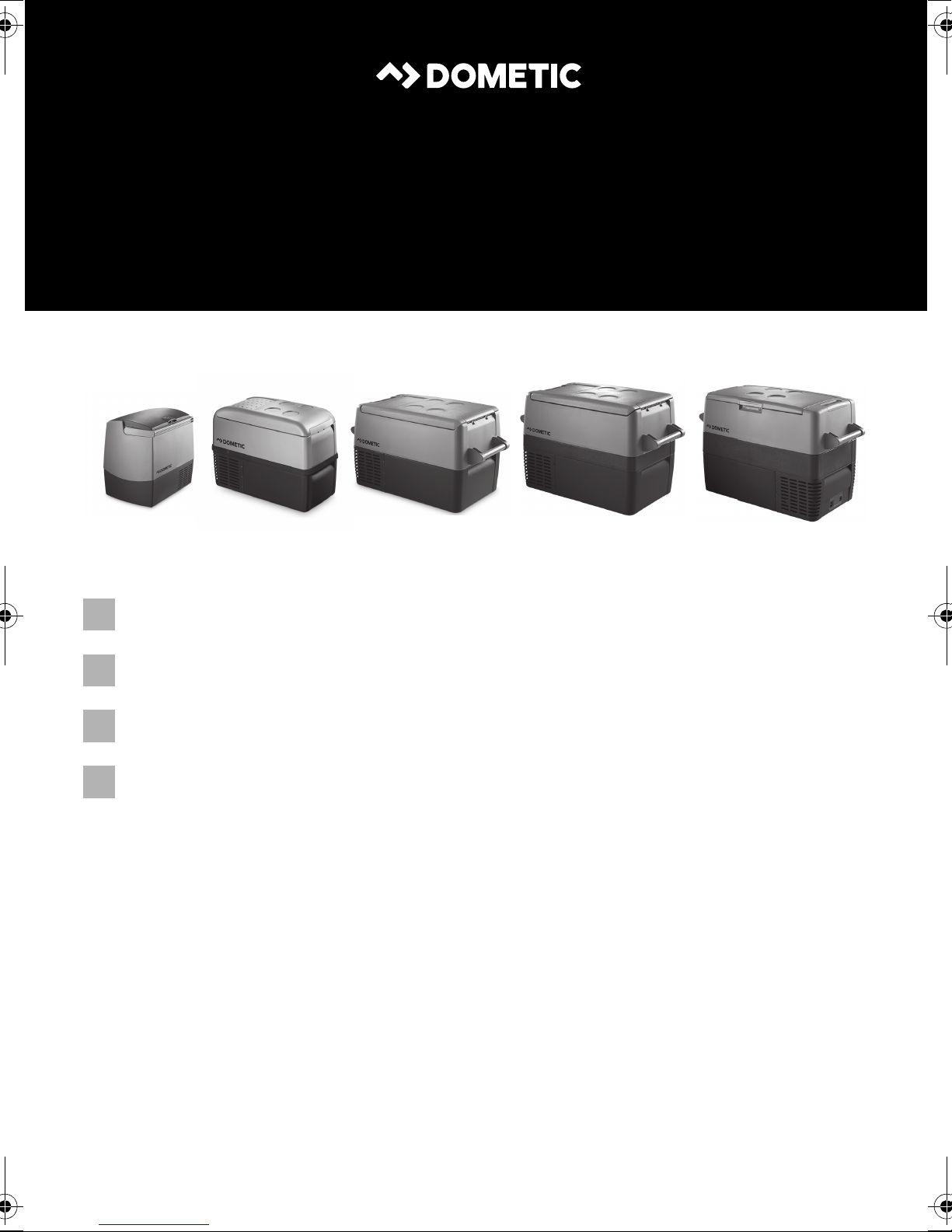
CF18, CF25, CF35, CF40, CF50
4
2
3
1
1
1
CF 25, CF 35, CF 40
2
CF 18
1 2 3 4
5
3
3
Page 4
CF 25, CF 35, CF 40, CF 50
4
5
100-240V~AC
FUSE
12/24V DC
1
2 3
CF 35, CF 40, CF 50
6
1
2
1
CF 35, CF 40, CF 50
7
1 3 4 5 6 72
POWER
ON
SET
OFF
ERROR
CF 25
CF18, CF25, CF35, CF40, CF50
°
UP
+
DOWN
–
1
4
Page 5
CF18, CF25, CF35, CF40, CF50
CF 50
AB
8
9
1 2
0
1 2 3
4
5
6
5
Page 6
EN
CF18, CF25, CF35, CF40, CF50
Please read this operating manual carefully before starting the device.
Keep it in a safe place for future reference. If the device is passed on to
another person, this operating manual must be handed over to the user
along with it.
The manufacturer cannot be held liable for damage resulting from improper usage
or incorrect operation.
Contents
1 Explanation of symbols . . . . . . . . . . . . . . . . . . . . . . . . . . . . . . . . . . . . . . . .7
2 Safety instructions . . . . . . . . . . . . . . . . . . . . . . . . . . . . . . . . . . . . . . . . . . . .7
2.1 General safety . . . . . . . . . . . . . . . . . . . . . . . . . . . . . . . . . . . . . . . . . . . .7
2.2 Operating the device safely . . . . . . . . . . . . . . . . . . . . . . . . . . . . . . . . .9
3 Scope of delivery. . . . . . . . . . . . . . . . . . . . . . . . . . . . . . . . . . . . . . . . . . . . .10
4 Intended use. . . . . . . . . . . . . . . . . . . . . . . . . . . . . . . . . . . . . . . . . . . . . . . . .10
5 Function description. . . . . . . . . . . . . . . . . . . . . . . . . . . . . . . . . . . . . . . . . . 11
5.1 Scope of functions. . . . . . . . . . . . . . . . . . . . . . . . . . . . . . . . . . . . . . . . 11
5.2 Operating and display elements . . . . . . . . . . . . . . . . . . . . . . . . . . . .12
6Operation . . . . . . . . . . . . . . . . . . . . . . . . . . . . . . . . . . . . . . . . . . . . . . . . . . .14
6.1 Before initial use . . . . . . . . . . . . . . . . . . . . . . . . . . . . . . . . . . . . . . . . .14
6.2 Energy saving tips . . . . . . . . . . . . . . . . . . . . . . . . . . . . . . . . . . . . . . . .15
6.3 Connecting the cooler . . . . . . . . . . . . . . . . . . . . . . . . . . . . . . . . . . . .15
6.4 Using the battery monitor . . . . . . . . . . . . . . . . . . . . . . . . . . . . . . . . . .17
6.5 Using the cooler . . . . . . . . . . . . . . . . . . . . . . . . . . . . . . . . . . . . . . . . .19
6.6 Setting the temperature . . . . . . . . . . . . . . . . . . . . . . . . . . . . . . . . . . 20
6.7 Switching off the cooler . . . . . . . . . . . . . . . . . . . . . . . . . . . . . . . . . . .21
6.8 Defrosting the cooler . . . . . . . . . . . . . . . . . . . . . . . . . . . . . . . . . . . . .21
6.9 Replacing the AC fuse (CF35, CF40, CF50). . . . . . . . . . . . . . . . . . .21
6.10 Replacing the DC plug fuse . . . . . . . . . . . . . . . . . . . . . . . . . . . . . . . 22
6.11 Replacing the light bulb (CF25, CF35, CF40, CF50) . . . . . . . . . . 22
7 Cleaning and maintenance. . . . . . . . . . . . . . . . . . . . . . . . . . . . . . . . . . . 23
8Guarantee. . . . . . . . . . . . . . . . . . . . . . . . . . . . . . . . . . . . . . . . . . . . . . . . . . 23
9Troubleshooting . . . . . . . . . . . . . . . . . . . . . . . . . . . . . . . . . . . . . . . . . . . . 24
10 Disposal . . . . . . . . . . . . . . . . . . . . . . . . . . . . . . . . . . . . . . . . . . . . . . . . . . . . 25
11 Technical data . . . . . . . . . . . . . . . . . . . . . . . . . . . . . . . . . . . . . . . . . . . . . . 25
6
Page 7
EN
CF18, CF25, CF35, CF40, CF50 Explanation of symbols
1 Explanation of symbols
DANGER!
D
!
Safety instruction: Failure to observe this instruction will cause fatal or
serious injury.
WARNING!
Safety instruction: Failure to observe this instruction can cause fatal or
serious injury.
CAUTION!
Safety instruction: Failure to observe this instruction can lead to injury.
!
NOTICE!
A
Failure to observe this instruction can cause material damage and impair
the function of the product.
NOTE
Supplementary information for operating the product.
I
2 Safety instructions
2.1 General safety
WARNING!
• Do not operate the device if it is visibly damaged.
!
• If this device's power cable is damaged, it must be replaced by the
manufacturer, customer service or a similarly qualified person in order
to prevent safety hazards.
• This device may only be repaired by qualified personnel. Improper
repairs can lead to considerable hazards.
• This device can be used by children aged 8 years or over, as well as by
persons with diminished physical, sensory or mental capacities or a
lack of experience and/or knowledge, providing they are supervised
or have been taught how to use the device safely and are aware of the
resulting risks.
7
Page 8

EN
Safety instructions CF18, CF25, CF35, CF40, CF50
• Cleaning and user maintenance must not be carried out by children
without supervision.
• Children must not play with the device.
• Children must be supervised to ensure that they do not play with the
device.
• Always keep and use the device out of the reach of children under the
age of 8 years.
• Do not store any explosive substances such as spray cans with a
flammable propellant in the device.
CAUTION!
!
A
• Disconnect the device from the power supply
– before each cleaning and maintenance
– after every use
• Food may only be stored in its original packaging or in suitable
containers.
NOTICE!
• Check that the voltage specification on the type plate corresponds to
that of the energy supply.
• Only connect the device as follows:
– With the DC connection cable to the DC power supply
– Or with the AC connection cable to the AC power supply
• Never pull the plug out of the socket by the cable.
• If the cooler is connected to the DC socket: Disconnect the cooler and
other power consuming devices from the battery before connecting
the quick charging device.
• If the cooler is connected to the DC socket: Disconnect the cooler or
switch it off when you turn off the engine. Otherwise you may discharge the battery.
• The cooling device is not suitable for transporting caustic materials or
materials containing solvents.
• The cooling device contains inflammable cyclopentane in the
insulation. The gases in the insulation material require special disposal
procedures. Deliver the device at the end of its life-cycle to an appropriate recycling.
8
Page 9
EN
CF18, CF25, CF35, CF40, CF50 Safety instructions
2.2 Operating the device safely
CAUTION!
!
A
• Before starting the device, ensure that the power supply line and the
plug are dry.
NOTICE!
• Do not use electrical devices inside the cooler unless they are
recommended by the manufacturer for the purpose.
• Do not place the device near naked flames or other heat sources
(heaters, direct sunlight, gas ovens etc.).
• Danger of overheating!
Ensure at all times that there is sufficient ventilation so that the heat that
arises during operation does not build up. Make sure that the device
is sufficiently far away from walls and other objects so that the air can
circulate.
• Ensure that the ventilation openings are not covered.
• Do not fill the inner container with ice or fluid.
• Never immerse the device in water.
• Protect the device and the cable against heat and moisture.
9
Page 10
EN
Scope of delivery CF18, CF25, CF35, CF40, CF50
3Scope of delivery
No. in
fig. 1, page 3
1 1 Cooler
2 1 Connection cable for 12/24 Vg connection
31
42
–1Operating manual
Quantity Description
Only CF35, CF40, CF50
Connection cable for 120 Vw connection
Only CF35, CF40, CF50
Carrying handle, consisting of:
–2 holders
–1 handle
– 4 fastening screws
4 Intended use
The cooler is suitable for cooling and freezing foods.
The device is designed to be operated from:
• a 12 V
• a 12 V
• an AC power supply (CF35, CF40, CF50)
For operating CF 18, CF25 at 120 V
(accessory).
!
g or 24 Vg on-board power supply of a vehicle, boat or caravan
g or 24 Vg auxiliary battery
w you need an AC/DC mains rectifier
CAUTION! Health hazard!
Please check if the cooling capacity of the device is suitable for storing
the food or medicine you wish to cool.
10
Page 11
EN
CF18, CF25, CF35, CF40, CF50 Function description
5 Function description
The cooler can chill products, keep them cool as well as freeze them. A maintenance-free refrigerant circuit with compressor provides the cooling. The extra strong
insulation and powerful compressor ensure especially fast cooling.
The cooler is designed for mobile use and can be carried by using a folding carrying
bracket (CF18), two recessed grips (CF25) or two removable carrying handles
(CF35, CF40, CF50).
When used on boats, the cooler can withstand a short-term inclination of 30°.
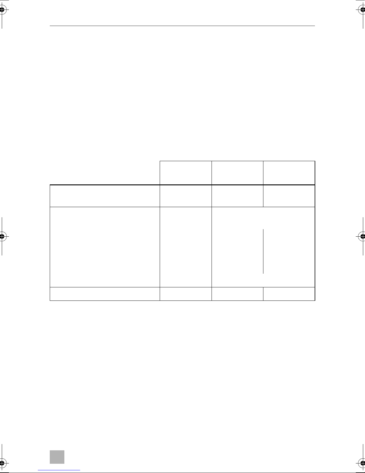
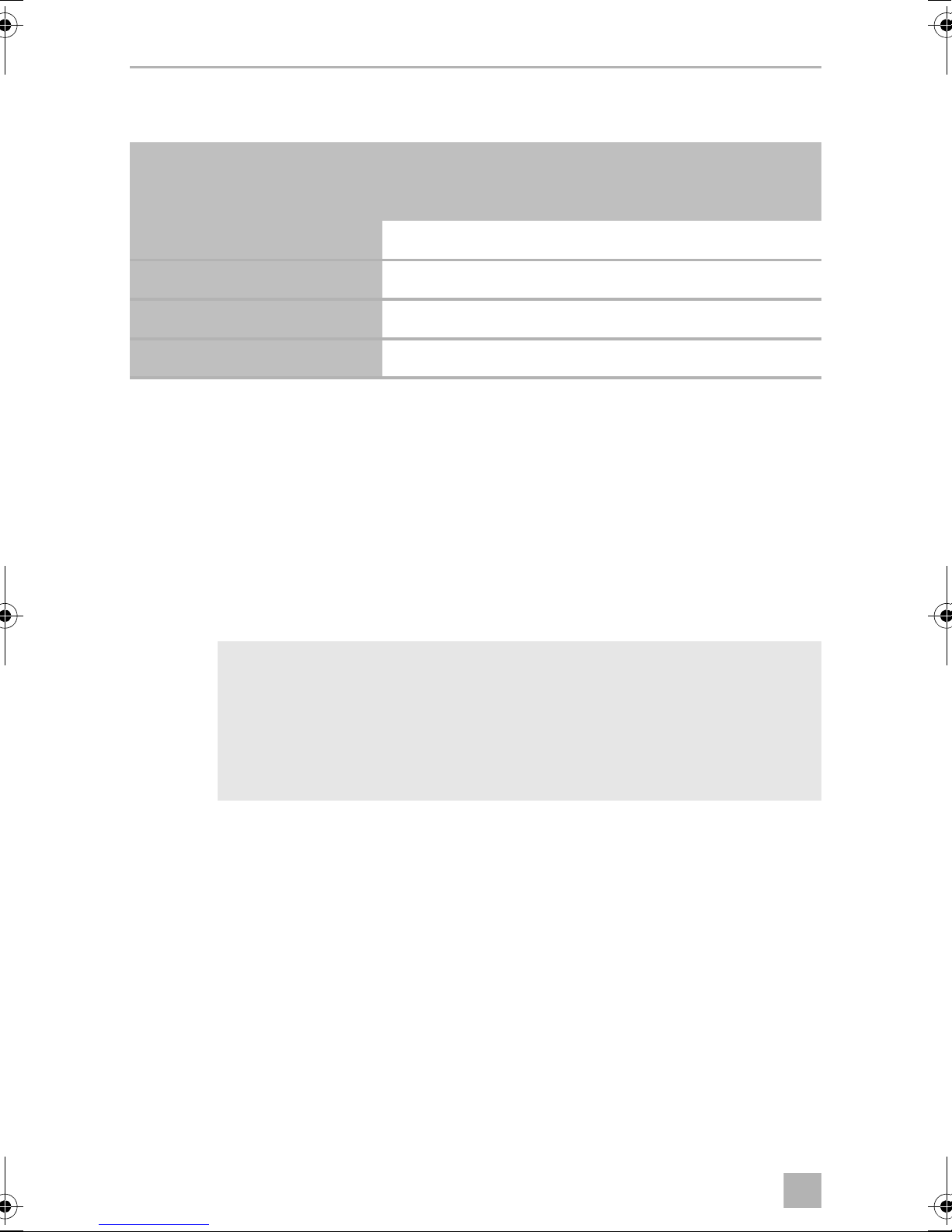
5.1 Scope of functions
CF18 CF25
Power supply with priority circuit for
connecting to the power supply –
Battery monitor to protect the
vehicle battery 2-level 3-level
Turbo mode for rapid cooling –
Display with temperature gauge
(switches off automatically at low
battery voltage)
Temperature setting rotary-knob two buttons in steps of 1 °C (2 °F)
Removable carrying handles –
–
–
–
CF35, CF40,
CF50
11
Page 12
EN
Function description CF18, CF25, CF35, CF40, CF50
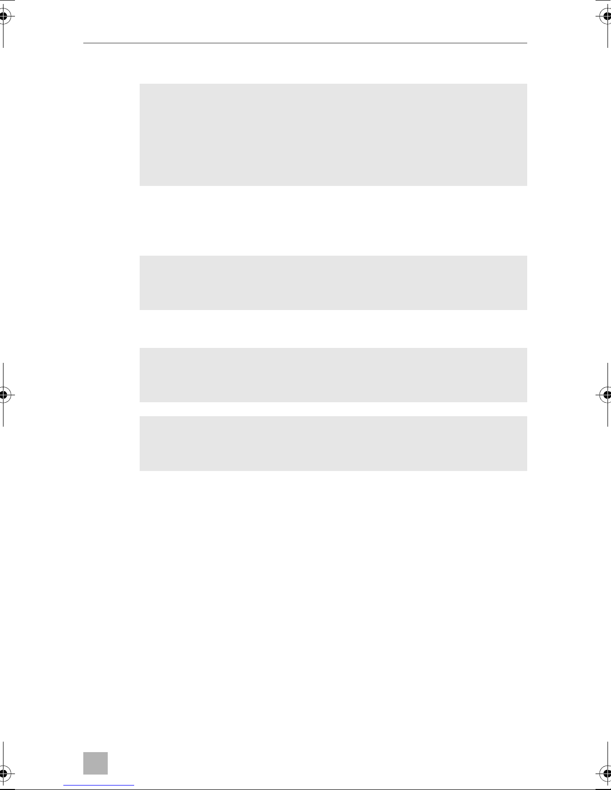
5.2 Operating and display elements
CF25, CF35, CF40
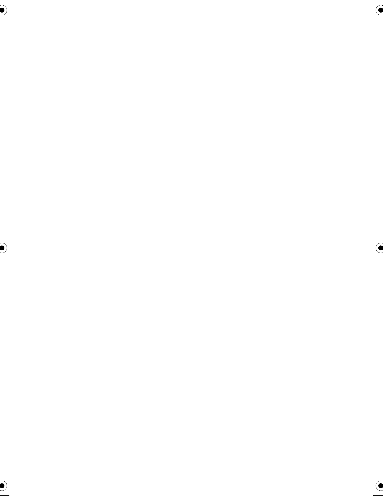
Lock for lid (fig. 2 1, page 3)
CF18
Operating panel and connection socket (fig. 3, page 3)
Item Description Explanation
1 TEMPERATURE Temperature controller,
cooling temperature at the end positions:
COLD: +10 °C (+50 °F)
FREEZE: –18 °C (0 °F)
2 POWER Status indication
LED lights up green: Device is switched on and
ready for operation
LED lights up yellow: Set temperature has been
reached
3 ERROR LED flashes red: Device is switched on but not
ready for operation
4 BATTERY MONITOR Switch-on device/battery monitor:
0: Device is switched off
HIGH: Device is switched on, battery
monitor is in HIGH mode
LOW: Device is switched on, battery
monitor is in LOW mode
5
12/24 Vg
Connection socket DC voltage supply
12
Page 13
EN
CF18, CF25, CF35, CF40, CF50 Function description
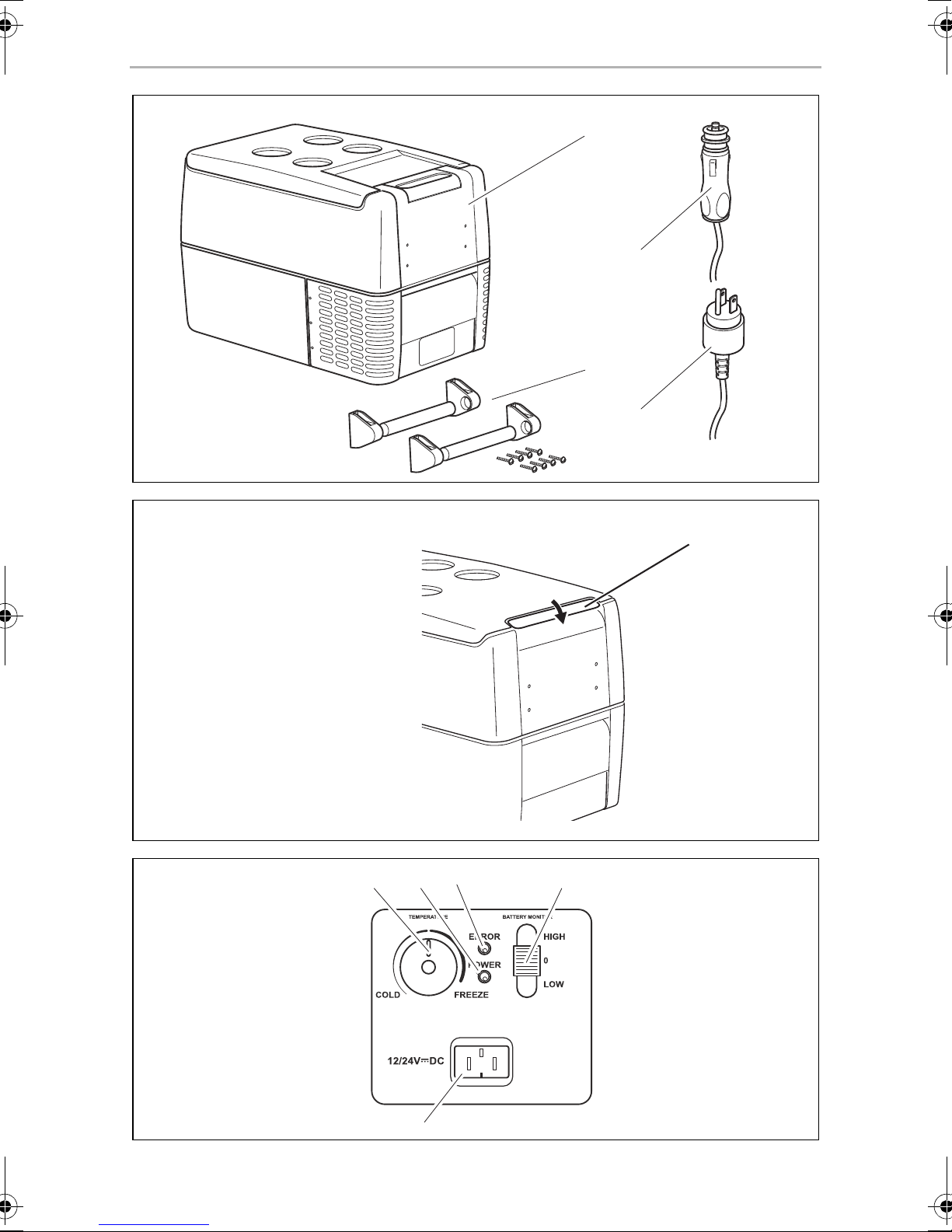
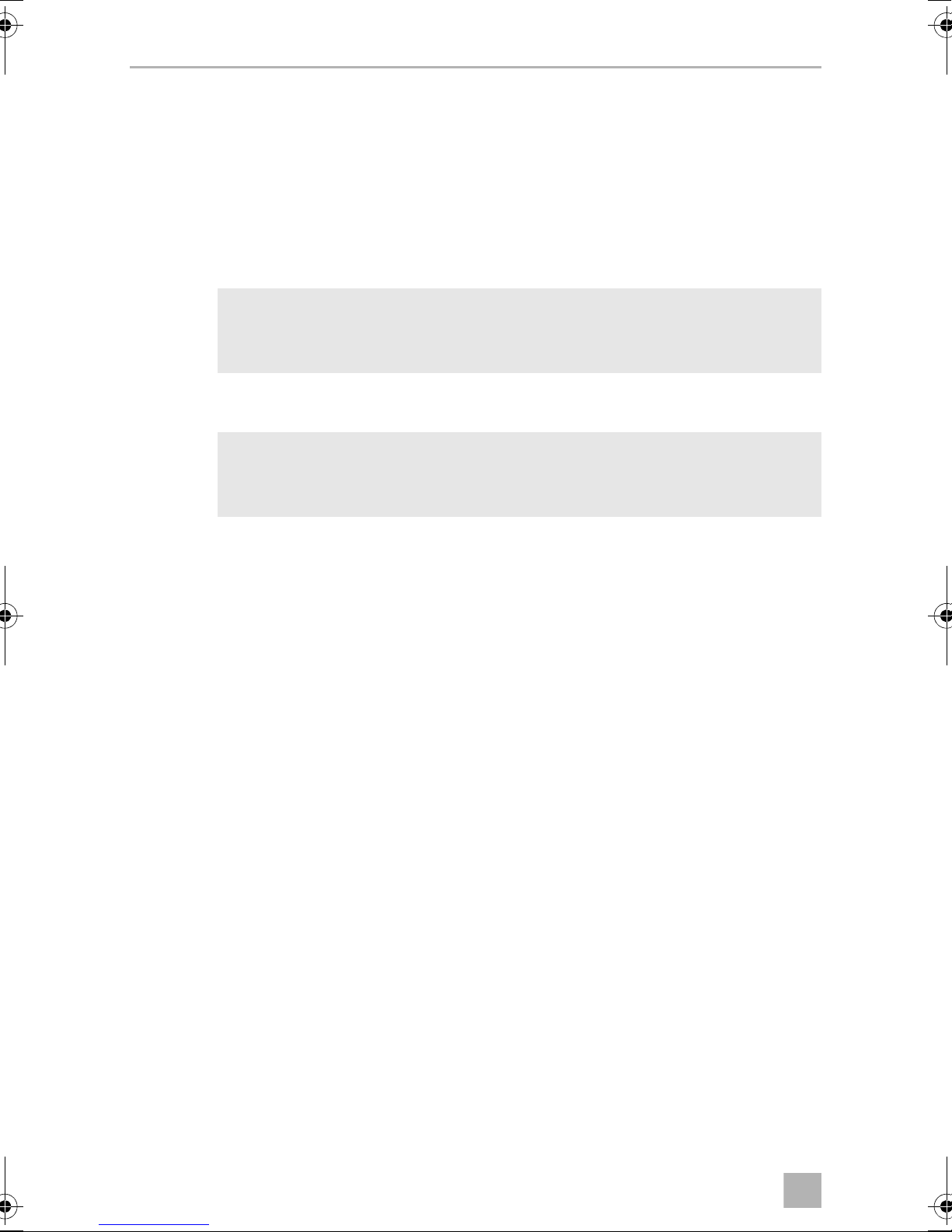
CF25, CF35, CF40, CF50
Operating panel (fig. 4, page 4)
Item Description Explanation
1ON
OFF
2 POWER Status indication
3 ERROR LED flashes red: Device is switched on but not
4 SET Selects the input mode
5 – Display, shows the information
6 UP + Press once to increase the value
Switches the cooler on or off when the button is pressed for
between one and two seconds
LED lights up green: Compressor is on
LED lights up orange: Compressor is off
LED flashes orange: Display switched off
automatically due to low
battery voltage
ready for operation
– Temperature setting
– Celsius or Fahrenheit display
– Set battery monitor
7 DOWN – Press once to decrease the value
CF25
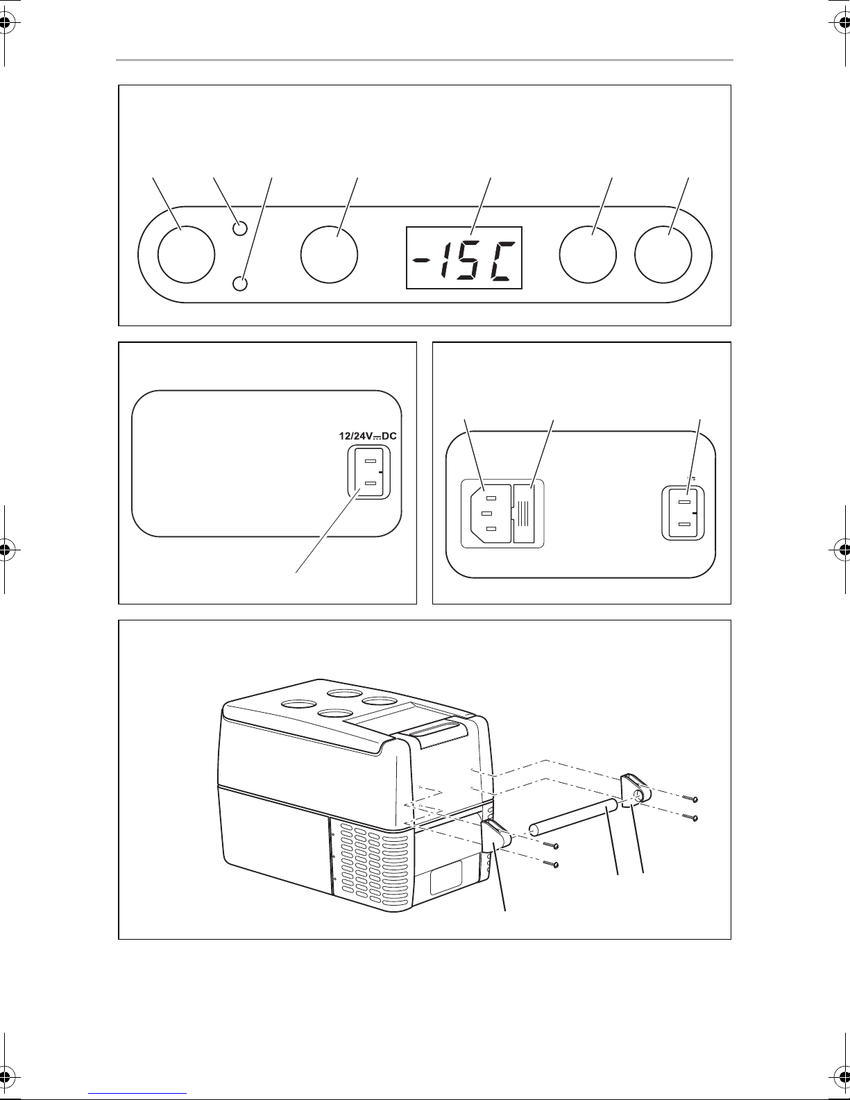
Connection sockets (fig. 5, page 4)
Item Description
1 Connection socket DC voltage supply
CF35, CF40, CF50
Connection sockets (fig. 6, page 4)
Item Description
1 Connection socket AC voltage supply
2Fuse holder
3 Connection socket DC voltage supply
13
Page 14
EN
Operation CF18, CF25, CF35, CF40, CF50
6Operation
6.1 Before initial use
NOTE
I
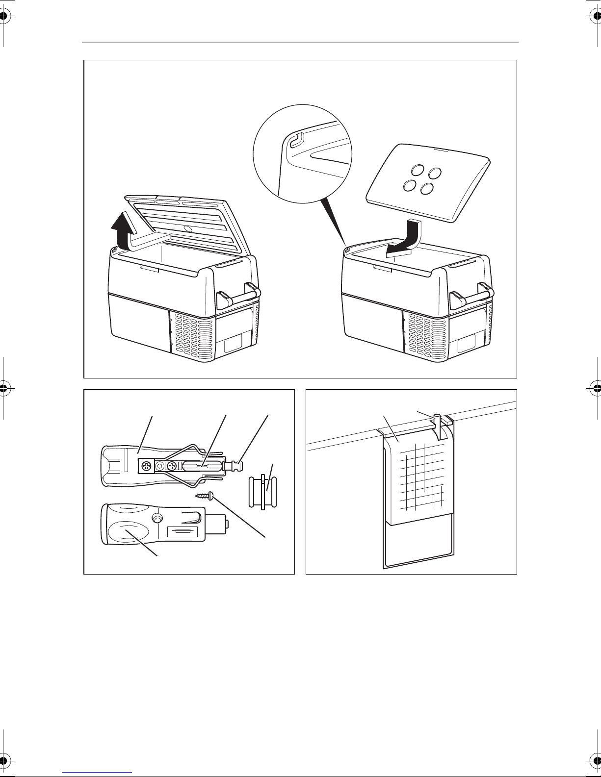
Mounting the handles (CF35, CF40, CF50)
The handles are enclosed unassembled. If you wish to attach the handles, proceed
as follows:
➤ Make a handle by putting two holders (fig. 7 1, page 4) and a handle (fig. 7 2,
page 4) together.
Before starting your new cooler for the first time, you should clean it
inside and outside with a damp cloth for hygienic reasons (please also
refer to the chapter “Cleaning and maintenance” on page 23).
➤ Fasten the grip with the enclosed screws in the holes provided.
Turning the lid stop around (CF50)
You can turn the lid stop around if you want to open the lid from the other side. To
do this, proceed as follows:
➤ Open the lid and pull it out (fig. 8 A, page 5).
➤ Turn the lid.
➤ Insert the lid in the lid holders on the side opposite the cooler (fig. 8 B, page 5).
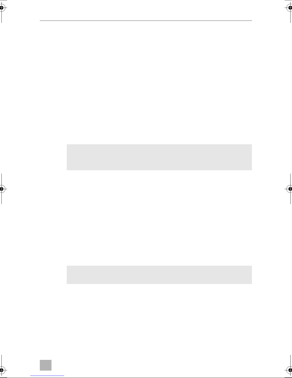
Selecting the temperature units (CF25, CF35, CF40, CF50)
You can switch the temperature display between Celsius and Fahrenheit. This is how
to do it:
➤ Switch on the cooler.
➤ Press the “SET” button (fig. 4 4, page 4) twice.
➤ Use the “UP +” (fig. 4 6, page 4) and “DOWN –” (fig. 4 7, page 4) buttons to
select Celsius or Fahrenheit.
✓ The selected temperature units then appear in the display for a few seconds. The
display flashes several times before it returns to the current temperature.
14
Page 15
EN
CF18, CF25, CF35, CF40, CF50 Operation
6.2 Energy saving tips
• Choose a well ventilated installation location which is protected against direct
sunlight.
• Allow warm food to cool down first before placing it in the cooling device to
keep cool.
• Do not open the cooling device more often than necessary.
• Do not leave the cooling device open for longer than necessary.
• Defrost the cooler once a layer of ice forms.
• Avoid unnecessary low temperatures.
6.3 Connecting the cooler
AC extension cord
WARNING!
!
!
➤ Select a UL/CSA listed 120 Vw/≥ 15 A outdoor use extension cord according to
the following table:
Because of potential safety hazards under certain conditions, the
manufacturer strongly recommends against the use of an extension
cord. However, if you must use an extension cord, it is absolutely
necessary that it be a UL-Listed (in the United States) or a CSA-Listed
(in Canada) appliance extension cord, with 15 A (minimum), 120 V
electrical ratings.
CAUTION!
• Under no circumstances should you attempt to splice extension
cord wires.
• Do not use power strips or 2-way splitters.
• Always unroll or uncoil an extension cord to avoid heat retention and
possible melting.
Maximum cord length
120 Vw
Wire conductors
AWG
10 ft. (3 m) 25 ft. (7.6 m) 50 ft. (15.2 m) 100 ft.
(30.5 m)
3333
14 (1.6 mm²) 12 (2 mm²) 12 (2 mm²) 12 (2 mm²)
15
Page 16
EN
Operation CF18, CF25, CF35, CF40, CF50
DC extension cord
CAUTION!
!
➤ Select a 12 V/24 Vg/≥ 10 A automotive use extension cord according to the
following table:
• The manufacturer does not recommend using any type of DC
extension cord.
• Under no circumstances should you attempt to splice extension
cord wires.
• Do not use power strips or 2-way splitters.
• Always unroll or uncoil an extension cord to avoid heat retention and
possible melting.
Maximum cord length
12 Vg
24 Vg
AWG
Connecting to a battery (vehicle or boat)
The cooler can be operated with 12 V
NOTICE! Danger of damage!
A
For safety reasons the cooler is equipped with an electronic system to prevent the
polarity reversal. This protects the cooler against short-circuiting when connecting to
a battery.
• Disconnect the cooler and other consumer units from the battery
before you connect the battery to a quick charging device.
Over-voltage can damage the electronics of the device.
• For protection of the device the DC cable supplied includes a fuse
inside the plug. Do not remove the fused DC plug.
Only use the DC cable supplied.
3 ft. (0.9 m) 6 ft. (1.8 m) 10 ft. (3 m) 12 ft. (3.7 m)
6 ft. (1.8 m) 10 ft. (3 m) 15 ft. (4.6 m) 25 ft. (7.6 m)
14 (1.6 mm²) 12 (2 mm²) 10 (2.6 mm²) 8 (3.3 mm²)
g or 24 Vg.
➤ Plug the DC power cord (fig. 1 2, page 3) into the DC voltage socket of the
cooler (fig. 5 1, page 4).
➤ Connect the power cord to the DC power outlet.
16
Page 17
EN
CF18, CF25, CF35, CF40, CF50 Operation
Connecting to a 120 V AC power supply (e.g. in the home or office)
(CF35, CF40, CF50)
DANGER! Danger of electrocution!
D
The coolers have an integrated multi-voltage power supply with priority circuit for
connecting to an AC voltage source of 120 V. The priority circuit automatically
switches the cooler to power supply operation, if the device is connected to a 120 V
AC power supply, even if the DC connection cable is still attached.
When switching between the AC power supply and the battery supply, the red LED
may light up briefly.
• Never handle plugs and switches with wet hands or if you are
standing on a wet surface.
• If you are operating your cooler on board a boat from a power supply
connection of 120 V
breaker between the 120 V AC power supply and the cooler.
Seek advice from a trained technician.
w, you must install a residual current circuit
➤ Plug the AC power cord (fig. 1 3, page 3) into the AC voltage socket of the
cooler (fig. 6 1,page 4).
➤ Connect the power cord to the AC power outlet.
6.4 Using the battery monitor
The device is equipped with a multi-level battery monitor that protects your vehicle
battery against excessive discharging when the device is connected to the on-board
12/24 V supply.
If the cooler is operated when the vehicle ignition is switched off, the cooler switches
off automatically as soon as the supply voltage falls below a set level. The cooler will
switch back on once the battery has been recharged to the restart voltage level.
NOTICE! Danger of damage!
A
When switched off by the battery monitor, the battery will no longer be
fully charged. Avoid continous starting and shutting off of the vehicles
engine when using the cooler in an automotive environment. Allow the
vehicle to recharge the battery before powering the cooler on.
17
Page 18
EN
Operation CF18, CF25, CF35, CF40, CF50
In “HIGH” mode, the battery monitor responds faster than at the levels “LOW” and
“MED” (see the following table).
CF18 CF25, CF35, CF40, CF50
Battery monitor mode LOW HIGH LOW MED HIGH
Switch-off voltage at 12 V
Restart voltage at 12 V
Switch-off voltage at 24 V
Restart voltage at 24 V
Selecting the battery monitor mode (CF25, CF35, CF40, CF50)
➤ Switch on the cooler.
➤ Press the “SET” button (fig. 4 4, page 4) three times.
➤ Use the “UP +” (fig. 4 6, page 4) and “DOWN –” (fig. 4 7, page 4) buttons to
select the battery monitor mode.
✓ The selected mode then appears in the display for a few seconds. The display
flashes several times before it returns to the current temperature.
NOTE
I
When the cooler is supplied by the starter battery, select the battery
monitor mode “HIGH”. If the cooler is connected to a supply battery,
the battery monitor mode “LOW” will suffice.
If you wish to operate the cooler from the AC power supply, set the
battery monitor to the “LOW” position.
10.4 V 11.5 V 10.1 V 11.4 V 11.8 V
11.5 V 12.5 V 11.1 V 12.2 V 12.6 V
22.1 V 24.0 V 21.5 V 24.1 V 24.6 V
23.6 V 25.4 V 23.0 V 25.3 V 26.2 V
18
Page 19
EN
CF18, CF25, CF35, CF40, CF50 Operation
6.5 Using the cooler
NOTICE! Danger of overheating!
A
➤ Place the cooler on a firm foundation.
Make sure that the ventilation slots are not covered and that the heated air can
dissipate.
I
Ensure at all times that there is sufficient ventilation so that the heat that
generated during operation can dissipate. Ensure that the ventilation
slots are not covered. The cooler MUST maintain a MINIMUM of
2 inches (51 mm) away from walls or similar surfaces which could restrict
important air flow requirements of the cooling system.
NOTE
Place the cooler as shown (fig. 1, page 3). If you operate the box in a
different position it can be damaged.
➤ Close the cooler, see chapter “Connecting the cooler” on page 15.
NOTE
I
A
CF18
➤ Set the slide switch (fig. 3 4, page 3) to "HIGH" when your providing power
from your vehicle's DC power source.
➤ Set the slide switch (fig. 3 4, page 3) to "LOW" when you providing power
from an external DC power supply source.
✓ The “POWER” LED is lit green.
✓ The cooler starts cooling the interior.
If you wish to operate the cooler from the AC power supply, set the
battery monitor to the “LOW” position.
NOTICE! Danger from excessively low temperature!
Ensure that the only those objects are placed in the cooler that are
intended to be cooled at the selected temperature.
✓ When the cooling temperature has been reached, the “POWER” LED is yellow lit.
19
Page 20
EN
Operation CF18, CF25, CF35, CF40, CF50
CF25, CF35, CF40, CF50
➤ Press the “ON/OFF” button (fig. 4 1, page 4) for between one and two
seconds.
✓ The “POWER” LED lights up.
✓ The display (fig. 4 5, page 4) switches on and shows the current cooling
temperature.
NOTE
I
✓ The cooler starts cooling the interior.
I
The temperature displayed is that of the middle of the interior.
The temperatures elsewhere can deviate from this temperature.
NOTE
When operating with the battery, the display switches off automatically
if the battery voltage is low. The LED “POWER” flashes orange.
Locking the cooler (CF35, CF40)
➤ Close the lid.
➤ Press the lock (fig. 2 1, page 3) down, until it latches in place audibly.
6.6 Setting the temperature
CF18
➤ Set the cooling temperature with the temperature controller (fig. 3 1, page 3).
CF25, CF35, CF40, CF50
➤ Press the “SET” button (fig. 4 4, page 4) once.
➤ Use the “UP +” (fig. 4 6, page 4) and “DOWN –” (fig. 4 7, page 4) buttons to
select the cooling temperature.
✓ The cooling temperature appears in the display for a few seconds. The display
flashes several times and then the current temperature is displayed again.
20
Page 21
EN
CF18, CF25, CF35, CF40, CF50 Operation
6.7 Switching off the cooler
➤ Empty the cooler.
➤ Switch the cooler off.
➤ Pull out the connection cable.
If you do not want to use the cooler for a longer period of time:
➤ Leave the cover slightly open. This prevents odor build-up.
6.8 Defrosting the cooler
Humidity can form frost in the interior of the cooling device or on the vaporizer. This
reduces the cooling capacity. Defrost the device in good time to avoid this.
NOTICE! Danger of damage!
A
Never use hard or pointed tools to remove ice or to loosen objects
which have frozen in place.
To defrost the cooler, proceed as follows:
➤ Take out the contents of the cooling device.
➤ If necessary, place them in another cooling device to keep them cool.
➤ Switch off the device.
➤ Leave the cover open.
➤ Wipe off the defrosted water.
6.9 Replacing the AC fuse (CF35, CF40, CF50)
DANGER! Danger of electrocution!
Disconnect the connection cable before you replace the device fuse.
D
➤ Pull off the connection cable.
➤ Pry out the fuse insert (fig. 6 2, page 4) with a screwdriver.
➤ Replace the defective fuse with a new one that has the same rating (T4AL 250 V).
➤ Press the fuse insert back into the housing.
21
Page 22
EN
Operation CF18, CF25, CF35, CF40, CF50
6.10 Replacing the DC plug fuse
➤ Pull the adapter sleeve (fig. 9 4, page 5) off of the plug.
➤ Unscrew the screw (fig. 9 5, page 5) out of the upper half of the housing
(fig. 9 1, page 5).
➤ Carefully raise the upper half of the housing from the lower (fig. 9 6, page 5)
half.
➤ Take out the contact pin (fig. 9 3, page 5).
➤ Replace the defective fuse (fig. 9 2, page 5) with a new fuse of the same type
and rating (3AG, Fast Acting, 10 A).
➤ Re-assemble the plug in the reverse order.
6.11 Replacing the light bulb (CF25, CF35, CF40, CF50)
➤ Press the switch pin (fig. 0 2, page 5) downwards so that the transparent part
(fig. 0 1, page 5) of the lamp can be removed at the front.
➤ Replace the light bulb.
NOTE
I
➤ Press the transparent part of the lamp back into the housing.
The LEDs in the light bulb must be aligned with the transparent part of
the lamp.
22
Page 23
EN
CF18, CF25, CF35, CF40, CF50 Cleaning and maintenance
7 Cleaning and maintenance
WARNING!
!
A
➤ Occasionally clean the device interior and exterior with a damp cloth.
➤ Make sure that the air inlet and outlet vents on the device are free of any dust and
dirt, so that heat can be released and the device is not damaged.
Always disconnect the device from the power supply before you clean
and service it.
NOTICE! Risk of damage
• Never clean the cooler under running water or in dish water.
• Do not use abrasive cleaning agents or hard objects during cleaning
as these can damage the cooler.
8Guarantee
The statutory warranty period applies. If the product is defective, please contact the
manufacturer's branch in your country (see the back of the instruction manual for the
addresses) or your retailer.
For repair and guarantee processing, please include the following documents when
you send in the device:
• A copy of the receipt with purchasing date
• A reason for the claim or description of the fault
23
Page 24
EN
Troubleshooting CF18, CF25, CF35, CF40, CF50
9 Troubleshooting
Fault Possible cause Suggested remedy
Device does not
function, LED does
not glow.
The device does not
cool (plug is inserted,
“POWER” LED is lit).
The device does not
cool (plug is inserted,
“POWER” LED flashes
orange, display is
switched off).
No voltage was
detected in the DC
power outlet.
No voltage present in
the AC voltage outlet.
The device fuse is
defective.
The integrated power
supply adapter is
defective.
Defective compressor. This can only be repaired by an
Battery voltage is too
low.
In most vehicles the ignition must be
turned on before power will be supplied
to the DC power outlet.
Try using another plug outlet.
Replace the device fuse, see chapter
“Replacing the AC fuse (CF35, CF40,
CF50)” on page 21.
This can only be repaired by an
authorized repair center.
authorized repair center.
Test the battery and charge it as needed.
When operating from
the DC outlet:
The ignition is on
and the device is not
working and the LED
is not lit.
The display shows an
error message (e.g.
“Err1”) and the appliance does not cool.
The DC outlet is dirty.
This results in a poor
electrical contact.
The fuse of the DC plug
has blown.
The vehicle fuse has
blown.
The appliance has
switched off due to an
internal fault.
If the plug of your cooler becomes very
warm in the DC outlet, either the DC
outlet must be cleaned or the plug has
not been assembled correctly.
Replace the fuse in the DC plug, see
chapter “Replacing the DC plug fuse” on
page 22.
Replace the vehicle’s DC outlet fuse.
Please refer to your vehicle’s operating
manual.
This can only be repaired by an
authorized repair center.
24
Page 25
EN
CF18, CF25, CF35, CF40, CF50 Disposal
10 Disposal
➤ Place the packaging material in the appropriate recycling waste bins wherever
possible.
If you wish to finally dispose of the product, ask your local recycling centre
or specialist dealer for details about how to do this in accordance with the
M
applicable disposal regulations.
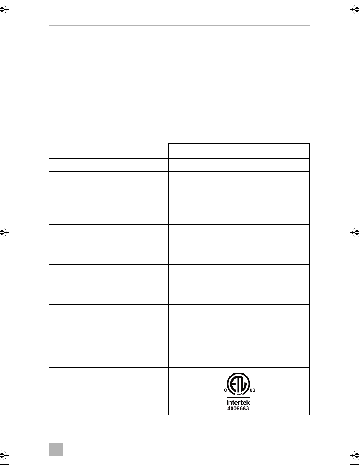
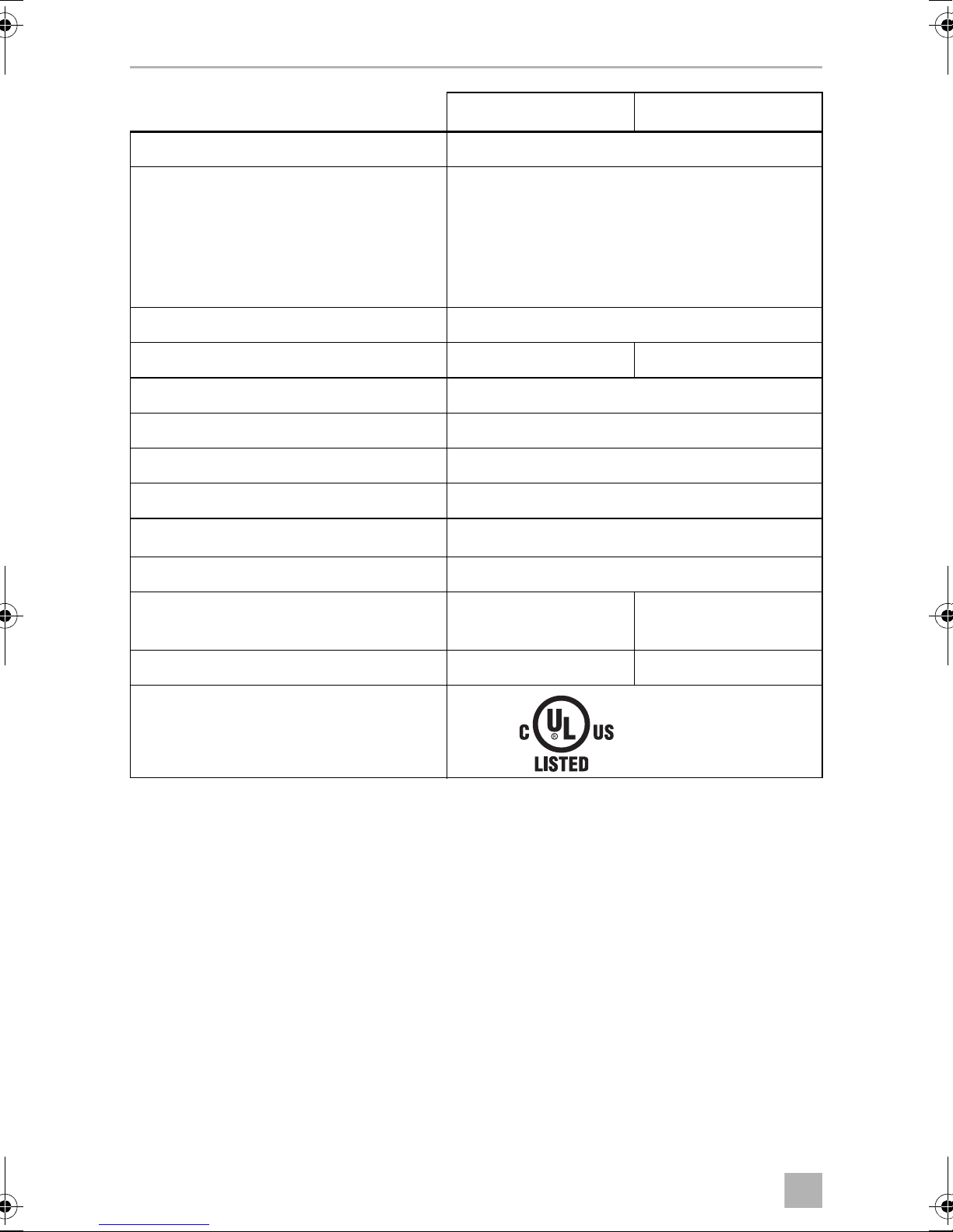
11 Technical data
CF18 CF25
Connection voltage: 12/24 Vg
Rated current
– 12 Vg: 7.0 A 7.0 A
– 24 Vg:3.0A 3.0A
– 120 Vw:––
Cooling capacity: +10 °C to –18 °C (+50 °F to +0.4 °F)
Usable capacity: 18 l (0.64 cu. ft.) 23 l (0.82 cu. ft.)
Climate class: N, ST, T
Ambient temperature: 18 °C to 43 °C (+50 °F to 109.4 °F)
Noise emission: –
Refrigerant quantity: 38 g (1.34 oz.) 40 g (1.41 oz.)
equivalent: 0.054 t (119.05 lb.) 0.057 t (125.66 lb.)
CO
2
Global warming potential (GWP): 1430
Dimensions (W x H x D) in mm (in.): 300 x 414 x 465
(11.81 x 16.30 x 18.31)
Weight: 12 kg (26.46 lb.) 12.7 kg (28 lb.)
260 x 425 x 550
(10.24 x 16.73 x 21.65)
Test/certificates:
25
Page 26
EN
Technical data CF18, CF25, CF35, CF40, CF50
CF35 CF40
Connection voltage: 12/24 Vg and 120 Vw
Rated current
– 12 Vg:7.0 A
– 24 Vg:3.0 A
– 120 Vw:1.4 A
Cooling capacity: +10 °C to –18 °C (+50 °F to +0.4 °F)
Usable capacity: 31 l (1.1 cu. ft.) 36 l (1.3 cu. ft.)
Climate class: N, ST, T
Ambient temperature: 18 °C to 43 °C (+50 °F to 109.4 °F)
Noise emission: 45 dB(A)
Refrigerant quantity: 42 g (1.48 oz.)
equivalent: 0.060 t (132.28 lb.)
CO
2
Global warming potential (GWP): 1430
Dimensions (W x H x D) in mm (in.): 360 x 385 x 580
(14.17 x 15.16 x 22.83)
Weight: 15.5 kg (34.61 lb.) 17.2 kg (37.92 lb.)
360 x 445 x 580
(14.17 x 17.52 x 22.83)
Test/certificates:
File No: SA12891
26
Page 27
EN
CF18, CF25, CF35, CF40, CF50 Technical data
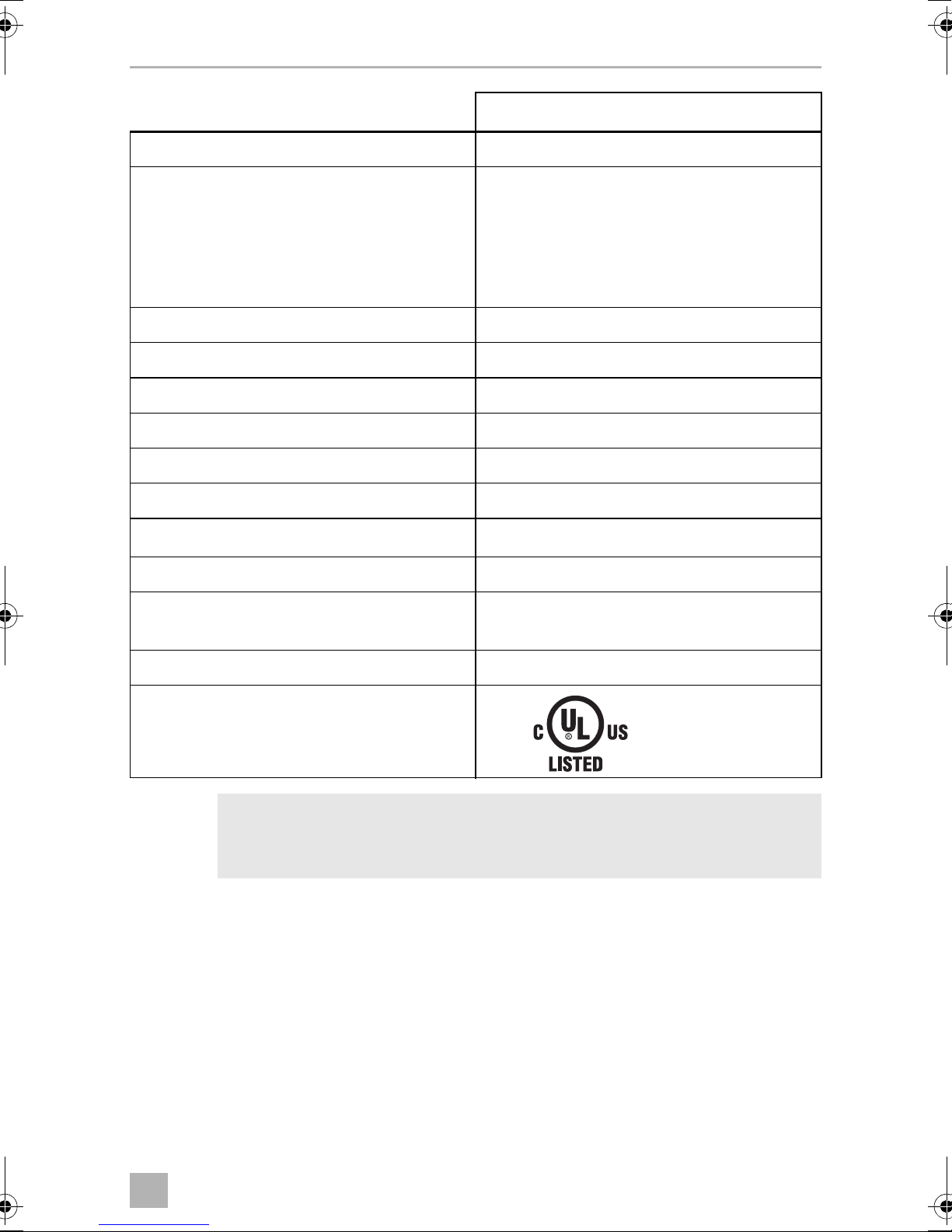
CF50
Connection voltage: 12/24 Vg and 120 Vw
Rated current
– 12 Vg:7.0 A
– 24 Vg:3.0 A
– 120 Vw:1.4 A
Cooling capacity: +10 °C to –18 °C (+50 °F to +0.4 °F)
Usable capacity: 47 l (1.7 cu. ft.)
Climate class: N, ST, T
Ambient temperature: 18 °C to 43 °C (+64.4 °F to 109.4 °F)
Noise emission: 45 dB(A)
Refrigerant quantity: 45 g (1.59 oz.)
equivalent: 0.064 t (141.1 lb.)
CO
2
Global warming potential (GWP): 1430
Dimensions (W x H x D) in mm (in.): 360 x 480 x 630
(14.17 x 18.9 x 24.8)
Weight: 18 kg (39.68 lb.)
Test/certificates:
File No: SA12891
NOTE
I
The refrigerant circuit contains R134a.
Contains fluorinated greenhouse gases
Hermetically sealed equipment
If the ambient temperature is above +32 °C (+90 °F), the minimum
temperature cannot be attained.
27
Page 28

FR
CF18, CF25, CF35, CF40, CF50
Veuillez lire ce manuel avec attention avant de mettre l’appareil en
service. Conservez ensuite ce manuel. En cas de passer de l’appareil,
veuillez le transmettre au nouvel acquéreur.
Le fabricant décline toute responsabilité en cas de dommages provoqués par une
utilisation non-conforme de l'appareil ou par des erreurs de manipulation.
Sommaire
1 Explication des symboles . . . . . . . . . . . . . . . . . . . . . . . . . . . . . . . . . . . . 29
2 Consignes de sécurité . . . . . . . . . . . . . . . . . . . . . . . . . . . . . . . . . . . . . . . 29
2.1 Consignes générales de sécurité . . . . . . . . . . . . . . . . . . . . . . . . . . . 29
2.2 Consignes de sécurité concernant le fonctionnement de l'appareil 31
3 Contenu de la livraison . . . . . . . . . . . . . . . . . . . . . . . . . . . . . . . . . . . . . . 32
4Usage conforme . . . . . . . . . . . . . . . . . . . . . . . . . . . . . . . . . . . . . . . . . . . . 32
5 Description du fonctionnement. . . . . . . . . . . . . . . . . . . . . . . . . . . . . . . 33
5.1 Étendue des fonctions . . . . . . . . . . . . . . . . . . . . . . . . . . . . . . . . . . . 33
5.2 Éléments de commande et d'affichage . . . . . . . . . . . . . . . . . . . . . . 34
6 Utilisation . . . . . . . . . . . . . . . . . . . . . . . . . . . . . . . . . . . . . . . . . . . . . . . . . . 36
6.1 Avant la première utilisation . . . . . . . . . . . . . . . . . . . . . . . . . . . . . . . 36
6.2 Comment économiser de l'énergie ? . . . . . . . . . . . . . . . . . . . . . . . 37
6.3 Raccordement de la glacière . . . . . . . . . . . . . . . . . . . . . . . . . . . . . . 37
6.4 Utilisation du protecteur de batterie . . . . . . . . . . . . . . . . . . . . . . . . 39
6.5 Utilisation de la glacière . . . . . . . . . . . . . . . . . . . . . . . . . . . . . . . . . . . 41
6.6 Réglage de la température . . . . . . . . . . . . . . . . . . . . . . . . . . . . . . . . 42
6.7 Extinction de la glacière . . . . . . . . . . . . . . . . . . . . . . . . . . . . . . . . . . 43
6.8 Dégivrage de la glacière. . . . . . . . . . . . . . . . . . . . . . . . . . . . . . . . . . 43
6.9 Remplacer le fusible CA (CF35, CF40, CF50) . . . . . . . . . . . . . . . . 43
6.10 Remplacement du fusible du connecteur (CC) . . . . . . . . . . . . . . . . 44
6.11 Remplacement de l'ampoule (CF25, CF35, CF40, CF50) . . . . . . 44
7 Nettoyage et entretien . . . . . . . . . . . . . . . . . . . . . . . . . . . . . . . . . . . . . . 44
8Garantie. . . . . . . . . . . . . . . . . . . . . . . . . . . . . . . . . . . . . . . . . . . . . . . . . . . . 45
9 Guide de dépannage . . . . . . . . . . . . . . . . . . . . . . . . . . . . . . . . . . . . . . . . 45
10 Élimination des déchets. . . . . . . . . . . . . . . . . . . . . . . . . . . . . . . . . . . . . . 46
11 Caractéristiques techniques. . . . . . . . . . . . . . . . . . . . . . . . . . . . . . . . . . 47
28
Page 29

FR
CF18, CF25, CF35, CF40, CF50 Explication des symboles
1 Explication des symboles
DANGER !
D
!
!
A
Consigne de sécurité : le non-respect de ces consignes entraîne la
mort ou de graves blessures.
AVERTISSEMENT !
Consigne de sécurité : le non-respect de ces consignes peut entraîner
la mort ou de graves blessures.
ATTENTION !
Consigne de sécurité : le non-respect de ces consignes peut entraîner
des blessures.
AVIS !
Le non-respect de ces consignes peut entraîner des dommages
matériels et des dysfonctionnements du produit.
REMARQUE
Informations complémentaires sur l'utilisation du produit.
I
2 Consignes de sécurité
2.1 Consignes générales de sécurité
AVERTISSEMENT !
• Si l'appareil présente des dégâts visibles, ne le mettez pas en service.
!
• Si le câble de raccordement de l'appareil est endommagé, il doit être
remplacé par le fabricant, son service après-vente ou une personne de
qualification similaire, afin d'éviter tout danger.
• Seul un personnel qualifié est habilité à effectuer des réparations sur
l'appareil. Des réparations inadéquates peuvent engendrer des
risques considérables.
29
Page 30

FR
Consignes de sécurité CF18, CF25, CF35, CF40, CF50
• Les enfants âgés de 8 ans et plus ainsi que les personnes ayant des
déficiences physiques, sensorielles ou mentales ou un manque
d'expérience et/ou de connaissances peuvent utiliser ce produit à
condition d'être sous surveillance ou d'avoir reçu des instructions
concernant l'utilisation de l'appareil en toute sécurité et d'avoir
compris les dangers qui en résultent.
• Le nettoyage et l’entretien ne doivent pas être effectués par des
enfants sans surveillance.
• Les enfants ne doivent pas jouer avec cet appareil.
• Les enfants doivent être surveillés pour s'assurer qu'ils ne jouent pas
avec l'appareil.
• Placez et utilisez l'appareil hors de portée des enfants de moins de
8ans.
• Ne stockez aucune substance explosive comme p.ex. des aérosols
contenant des agents propulseurs inflammables dans l'appareil.
!
A
ATTENTION !
• Coupez l'alimentation en courant de l'appareil
– avant tout nettoyage et entretien
– après chaque utilisation
• Les produits alimentaires doivent être conservés dans leurs emballages originaux ou dans des récipients appropriés.
AVIS !
• Vérifiez que la tension indiquée sur la plaque signalétique correspond
à l'alimentation électrique dont vous disposez.
• Raccordez l’appareil uniquement comme indiqué ci-dessous :
– Avec le câble de raccordement CC au réseau alternatif CC
– ou avec le câble de raccordement CA au réseau alternatif CA
• Ne tirez jamais sur le câble de raccordement pour sortir la fiche de la
prise.
• Si l’appareil de réfrigération est raccordé à la prise de courant
continu : débranchez de la batterie du véhicule l’appareil de réfrigération et les autres consommateurs d'énergie avant de raccorder un
chargeur rapide.
• Si l’appareil de réfrigération est raccordé à la prise de courant
continu : débranchez ou éteignez l’appareil de réfrigération lorsque
vous éteignez le moteur. Dans le cas contraire, il se pourrait que la
batterie se décharge.
30
Page 31

FR
CF18, CF25, CF35, CF40, CF50 Consignes de sécurité
• L'appareil de réfrigération n’est pas adapté pour le transport des
matières caustiques ou contenant des solvants.
• L'appareil de réfrigération contient du cyclopentane inflammable
dans son isolation. Les gaz contenus dans le matériau d'isolation
exigent une procédure de retraitement particulière. À la fin de son
cycle de vie, remettre l’appareil à un recyclage approprié.
2.2 Consignes de sécurité concernant le fonctionnement
de l'appareil
ATTENTION !
!
A
• Avant de mettre l'appareil en service, assurez-vous que la ligne
d'alimentation électrique et le connecteur sont secs.
AVIS !
• N'exploitez aucun appareil électrique à l'intérieur de l’appareil de
réfrigération, sauf si le fabricant le recommande.
• Ne montez pas l'appareil près de flammes nues ou d'autres sources
de chaleur (chauffage, fours à gaz, etc.).
• Risque de surchauffe !
Garantissez en permanence une ventilation suffisante pour que la
chaleur qui se dégage pendant le fonctionnement ne s'accumule pas.
Veillez à ce que l'appareil se trouve à une distance suffisante des murs
ou des objets, de sorte que l'air puisse circuler.
• Assurez-vous que les ouvertures d'aération ne sont pas recouvertes.
• Ne remplissez pas le bac intérieur de substances liquides ou de glace.
• Ne plongez jamais l'appareil dans l'eau.
• Tenez l'appareil et les câbles à l'abri de la chaleur et de l'humidité.
31
Page 32

FR
Contenu de la livraison CF18, CF25, CF35, CF40, CF50
3 Contenu de la livraison
Pos. dans
fig. 1, page 3
11Glacière
2 1 Câble de raccordement pour raccordement 12/24 Vg
31
42
– 1 Notice d'utilisation
Quantité Description
Uniquement CF35, CF40, CF50
Douille de raccordement pour prise 120 Vw
Uniquement CF35, CF40, CF50
Poignée de transport, composée de :
– 2 supports
– 1 poignée
– 4 vis de fixation
4Usage conforme
La glacière est conçue pour la réfrigération et la congélation d'aliments.
L'appareil est conçu pour être utilisé sur :
• une prise de bord 12 V
• une batterie auxiliaire de 12 V
• une alimentation électrique CA (CF35, CF40, CF50)
Pour le fonctionnement des appareils CF 18, CF25 à 120 V
redresseur de courant CA/CC (accessoire).
ATTENTION ! Risque pour la santé
!
Veuillez vérifier si la puissance frigorifique de l'appareil correspond à la
température de conservation recommandée pour les aliments ou les
médicaments que vous souhaitez conserver au frais.
g ou 24 Vg du véhicule, du bateau ou de la caravane
g ou 24 Vg
w, vous avez besoin d’un
32
Page 33

FR
CF18, CF25, CF35, CF40, CF50 Description du fonctionnement
5 Description du fonctionnement
L'appareil de réfrigération permet de réfrigérer, de tenir au frais ou de congeler des
produits. La réfrigération est assurée par un circuit de refroidissement à compresseur
qui ne nécessite aucune maintenance. L’isolation extra forte et le puissant compresseur assurent un refroidissement particulièrement rapide.
La glacière est conçue pour une u tilisation mobile et peut être transpor tée en utilisant
un support de transport pliant (CF18), deux poignées encastrées (CF25) ou deux
poignées de amovibles (CF35, CF40, CF50).
En cas d'utilisation sur bateaux, l'appareil de réfrigération peut supporter une inclinaison à court terme de 30°.
5.1 Étendue des fonctions
CF18 CF25
Bloc d'alimentation avec raccordement prioritaire pour raccordement
sur une alimentation électrique
Protecteur de batterie pour protéger
la batterie du véhicule 2 niveaux 3 niveaux
Mode Turbo pour un refroidissement
rapide
Affichage avec indicateur de température (s’éteint automatiquement si la
tension de la batterie est faible)
Réglage de la température bouton rotatif deux boutons par pas de 1 °C
Poignées amovibles –
–
–
–
–
(et de 2 °F)
–
CF35, CF40,
CF50
33
Page 34

FR
Description du fonctionnement CF18, CF25, CF35, CF40, CF50
5.2 Éléments de commande et d'affichage
CF25, CF35, CF40
Verrouillage du couvercle (fig. 2 1, page 3)
CF18
Panneau de commande et prise de raccordement (fig. 3, page 3)
Repère Description Explication
1 TEMPÉRATURE Régulateur de température,
température de refroidissement dans les positions finales :
COLD : +10 °C (+50 °F)
FREEZE : -18 °C (0 °F)
2 POWER Indication d'état
La LED s'allume en vert : L'appareil est allumé et prêt à
fonctionner
La LED s'allume en jaune : la température de consigne a
été atteinte
3 ERROR La LED clignote en rouge : L'appareil est allumé mais n'est
pas prêt à fonctionner
4 APPAREIL DE
SURVEILLANCE
DE BATTERIE
5
12/24 Vg
Allumage de l'appareil/protecteur de batterie :
0 : l'appareil est éteint
HIGH : l'appareil est allumé, le moni-
teur de batterie est en mode
HIGH
LOW : l'appareil est allumé, le moni-
teur de batterie est en mode
LOW
Prise de raccordement de l'alimentation en tension continue
34
Page 35

FR
CF18, CF25, CF35, CF40, CF50 Description du fonctionnement
CF25, CF35, CF40, CF50
Panneau de commande (fig. 4, page 4)
Repère Description Explication
1ON
OFF
2 POWER Indication d'état
3 ERROR La LED clignote en rouge : L'appareil est allumé mais n'est
4 SET [régler] Sélection du mode de saisie
5 – Écran, affiche les valeurs
6 UP + Une pression sur cette touche augmente la valeur de saisie
Permet de mettre en marche ou d'arrêter la glacière en
appuyant une à deux secondes sur la touche
La LED s'allume en vert : Le compresseur est en marche
La LED s'allume en orange : Le compresseur est arrêté
La LED clignote en orange : Affichage éteint automatique-
ment en raison de la faible tension de la batterie
pas prêt à fonctionner
– Réglage de la température
– Affichage en Celsius ou Fahrenheit
– Réglage de la surveillance de la batterie
7 DOWN – Une pression sur cette touche diminue la valeur de saisie
CF25
Douilles de raccordement (fig. 5, page 4)
Repère Description
1 Prise de raccordement de l'alimentation en tension continue
CF35, CF40, CF50
Douilles de raccordement (fig. 6, page 4)
Repère Description
1 Prise de raccordement de l'alimentation en tension alternative
2 Porte-fusible
3 Prise de raccordement de l'alimentation en tension continue
35
Page 36

FR
Utilisation CF18, CF25, CF35, CF40, CF50
6Utilisation
6.1 Avant la première utilisation
REMARQUE
I
Montage des poignées (CF35, CF40, CF50)
Les poignées sont fournies non assemblées. Si vous souhaitez fixer les poignées,
procédez comme suit :
➤ Fabriquez une poignée en assemblant deux supports (fig. 7 1, page 4) et une
poignée (fig. 7 2, page 4).
Avant de mettre en service votre nouvelle glacière, vous devez, pour
des raisons d’hygiène, la nettoyer à l’intérieur et à l’extérieur à l’aide
d’un tissu humide (voir aussi chapitre « Nettoyage et entretien »,
page 44).
➤ Fixez la poignée en vissant les vis fournies dans les trous prévus.
Inversion de la butée des couvercles (CF50)
Vous pouvez retourner la butée du couvercle si vous voulez ouvrir celui-ci par l'autre
côté. Procédez comme représenté :
➤ Ouvrez le couvercle et retirez-le (fig. 8 A, page 5).
➤ Tournez le couvercle.
➤ Insérez le couvercle dans les supports du couvercle sur le côté opposé de la
glacière (fig. 8 B, page 5).
Sélection des unités de température (CF25, CF35, CF40, CF50)
Pour l'affichage de la température, vous pouvez choisir entre les valeurs en °Celsius
ou en °Fahrenheit. Voici comment faire :
➤ Mettez l'appareil de réfrigération en marche.
➤ Appuyez deux fois sur la touche « SET » (fig. 4 4, page 4).
➤ Sélectionnez Celsius ou Fahrenheit à l'aide des touches « UP + » (fig. 4 6,
page 4) ou « DOWN – » (fig. 4 7, pa ge 4 ).
✓ L'écran affiche l'unité de température sélectionnée pendant quelques secondes.
L'écran clignote plusieurs fois avant de revenir à l'affichage de la température
actuelle.
36
Page 37

FR
CF18, CF25, CF35, CF40, CF50 Utilisation
6.2 Comment économiser de l'énergie ?
• Choisissez un emplacement bien aéré et à l'abri du soleil.
• Laissez refroidir les aliments chauds avant de les déposer dans la glacière.
• Ne pas ouvrir la glacière plus souvent que nécessaire.
• Ne laissez pas la glacière ouverte plus longtemps que nécessaire.
• Dégivrez la glacière dès qu'une couche de glace s'est formée.
• Évitez les basses températures inutiles.
6.3 Raccordement de la glacière
Câble de rallonge CA
AVERTISSEMENT !
!
En raison de risques potentiels pour la sécurité sous certaines conditions, le fabricant déconseille fortement l'utilisation d'une rallonge.
Toutefois, si vous devez utiliser une rallonge, il est absolument
nécessaire qu'il s'agisse d'un câble de rallonge d'appareil sur liste
UL (aux États-Unis) ou CSA (au Canada), avec des valeurs nominales
de 15 A (minimum), 120 V.
ATTENTION !
!
➤ Sélectionnez un câble de rallonge listé UL/CSA de 120 Vw/≥ 15 A pour
l'utilisation extérieure, selon le tableau suivant :
120 Vw
Fils conducteurs
AWG
• En aucun cas vous ne devez tenter de coller des fils du câble de
rallonge.
• N'utilisez pas de bandes électriques ou de diviseurs à 2 voies.
• Toujours dérouler un câble de rallonge afin d’éviter la rétention de la
chaleur et la possibilité qu'il fonde.
Longueur maximale du cordon
10 ft. (3 m) 25 ft. (7,6 m) 50 ft. (15,2 m) 100 ft.
(30,5 m)
3333
14 (1.6 mm²) 12 (2 mm²) 12 (2 mm²) 12 (2 mm²)
37
Page 38

FR
Utilisation CF18, CF25, CF35, CF40, CF50
Câble de rallonge CC
ATTENTION !
!
➤ Sélectionnez un câble de rallonge listé de 12 V/24 Vg/≥ 10 A pour l'utilisation
automobile, selon le tableau suivant :
• Le fabricant déconseille d'utiliser tout type de câble de rallonge
CC.
• En aucun cas vous ne devez tenter de coller des fils du câble de
rallonge.
• N'utilisez pas de bandes électriques ou de diviseurs à 2 voies.
• Toujours dérouler un câble de rallonge afin d’éviter la rétention de la
chaleur et la possibilité qu'il fonde.
Longueur maximale du cordon
12 Vg
24 Vg
AWG
Raccordement à une batterie (véhicule ou bateau)
La glacière peut être utilisée sur une alimentation 12 V
AVIS ! Risque de dommages !
A
Pour des raisons de sécurité, la glacière est équipée d’un système électronique pour
empêcher l’inversion de polarité. Cela protège la glacière contre un court-circuit lors
de la connexion à une batterie.
• Débranchez la glacière et les autres consommateurs d'énergie de la
batterie avant de recharger la batterie avec un chargeur rapide.
Les surtensions peuvent endommager l'électronique des appareils.
• Pour la protection de l'appareil, le câble CC fourni comprend un
fusible à l'intérieur de la fiche. Ne retirez pas la fiche DC à fusible.
Utilisez uniquement le câble de raccordement fourni à la livraison.
3 ft. (0,9 m) 6 ft. (1,8 m) 10 ft. (3 m) 12 ft. (3,7 m)
6 ft. (1,8 m) 10 ft. (3 m) 15 ft. (4,6 m) 25 ft. (7,6 m)
14 (1.6 mm²) 12 (2 mm²) 10 (2,6 mm²) 8 (3,3 mm²)
g ou 24 Vg.
➤ Branchez le cordon d’alimentation CC (fig. 1 2, page 3) dans la prise de
tension CC de la glacière (fig. 5 1,page 4).
➤ Connectez le cordon d'alimentation à la prise de sortie CC.
38
Page 39

FR
CF18, CF25, CF35, CF40, CF50 Utilisation
Raccordement à une alimentation 120 V CA (p. ex. dans la maison ou au
bureau) (CF35, CF40, CF50)
DANGER ! Danger d'électrocution
D
Les glacières sont équipées d'un bloc d'alimentation intégré à tensions multiples
avec raccordement prioritaire pour branchement sur une tension alternative de
120 V. Le raccordement prioritaire permet de passer directement en fonctionnement sur secteur quand l'appareil est raccordé à un réseau de courant alternatif de
120 V, même si le câble de raccordement 12/24 V est encore branché.
Lors de la commutation entre l'alimentation secteur et l'alimentation de la batterie, la
LED rouge peut s'allumer brièvement.
• Ne vous approchez pas de prises ou de commutateurs lorsque vous
avez les mains mouillées ou les pieds dans l'eau.
• Si vous raccordez la glacière à bord d'un bateau à la tension 120 V
vous devez dans tous les cas brancher un disjoncteur différentiel
entre le circuit de courant alternatif 120 V et la glacière.
Veuillez vous renseigner auprès d'un spécialiste.
w,
➤ Branchez le cordon d’alimentation CA (fig. 1 3, page 3) dans la prise de
tension CA de la glacière (fig. 6 1,page 4).
➤ Connectez le cordon d'alimentation à la prise de sortie CA.
6.4 Utilisation du protecteur de batterie
Le conteneur réfrigérant est équipé d'un protecteur de batterie à plusieurs niveaux
qui protège la batterie de votre véhicule, afin d'éviter une décharge profonde
lorsqu'il est raccordé au réseau en courant 12/24 V.
Si l'appareil de réfrigération est mis en marche alors que l'allumage du véhicule est
éteint, il s'arrête automatiquement dès que la tension d'alimentation descend en
dessous d'une valeur réglable. L'appareil de réfrigération se remet en marche dès
que la batterie est rechargée et que la tension de rallumage est atteinte.
AVIS ! Risque de dommages !
A
En cas d'extinction par le protecteur de batterie, la batterie n'est plus
complètement chargée. Évitez le démarrage et l'arrêt continus du
moteur du véhicule lors de l'utilisation de la glacière dans un environnement automobile. Laissez le véhicule recharger la batterie avant d’allumer/éteindre la glacière.
39
Page 40

FR
Utilisation CF18, CF25, CF35, CF40, CF50
En mode « HIGH », le protecteur de batterie se met en marche plus rapidement
qu'en mode « LOW » ou « MED » (voir tableau suivant).
CF18 CF25, CF35, CF40, CF50
Mode protecteur de batterie LOW HIGH LOW MED HIGH
Tension d'arrêt à 12 V
Tension de redémarrage à
12 V
Tension d'arrêt à 24 V
Tension de redémarrage à
24 V
Sélection du mode de surveillance de la batterie
(CF25, CF 35, CF40, CF50)
➤ Mettez l'appareil de réfrigération en marche.
➤ Appuyez trois fois sur la touche « SET » (fig. 4 4, page 4).
➤ Sélectionnez le mode du protecteur de batterie à l'aide des touches « UP + »
(fig. 4 6, page 4) ou « DOWN – » (fig. 4 7, pa ge 4).
✓ L'écran affiche le mode sélectionné pendant quelques secondes. L'écran cli-
gnote plusieurs fois avant de revenir à l'affichage de la température actuelle.
10,4 V 11,5 V 10,1 V 11,4 V 11,8 V
11,5 V 12,5 V 11,1 V 12,2 V 12,6 V
22,1 V 24,0 V 21,5 V 24,1 V 24,6 V
23,6 V 25,4 V 23,0 V 25,3 V 26,2 V
I
REMARQUE
Lorsque l'appareil de réfrigération est alimenté par la batterie de démarrage, réglez le protecteur de batterie sur le mode « HIGH ». Lorsque
l'appareil de réfrigération est raccordé à une batterie d'alimentation, le
mode « LOW » suffit.
Lorsque vous voulez faire fonctionner l'appareil de réfrigération sur le
secteur à courant alternatif par un adaptateur secteur, réglez le protecteur de batterie sur la position « LOW ».
40
Page 41

FR
CF18, CF25, CF35, CF40, CF50 Utilisation
6.5 Utilisation de la glacière
AVIS ! Risque de surchauffe !
A
➤ Placez le réfrigérateur sur une surface stable.
Veillez à ce que les fentes d'aération ne soient pas recouvertes, afin que l'air
chaud puisse bien s'évacuer.
I
Garantissez en permanence une ventilation suffisante pour que la
chaleur générée pendant le fonctionnement puisse se dissiper.
Assurez-vous que les fentes d'aération ne sont pas recouvertes. La
glacière DOIT se trouver à un MINIMUM de 2 pouces (51 mm) des murs
ou des surfaces similaires qui pourraient restreindre les conditions
importantes de flux d’air du système de refroidissement.
REMARQUE
Placez la glacière comme illustré (fig. 1, page 3). Si la glacière est
utilisée dans une autre position, l’appareil risque d'être endommagé.
➤ Fermez la glacière, voir chapitre « Raccordement de la glacière », page 37.
REMARQUE
I
A
CF18
➤ Réglez le commutateur à glissière (fig. 3 4, page 3) sur « HIGH » lorsque
vous fournissez l'alimentation à partir de la source d'alimentation CC de votre
véhicule.
➤ Réglez le commutateur à glissière (fig. 3 4, page 3) sur « LOW » lorsque vous
fournissez l'alimentation à partir d'une source d'alimentation CC externe.
Lorsque vous voulez faire fonctionner l'appareil de réfrigération sur le
secteur à courant alternatif par un adaptateur secteur, réglez le protecteur de batterie sur la position « LOW ».
AVIS ! Risque de températures trop basses !
Veillez à ne déposer dans la glacière que des objets ou des aliments qui
peuvent être réfrigérés à la température sélectionnée.
✓ La LED « POWER » s'allume en vert.
✓ La glacière commence par la réfrigération du compartiment intérieur.
✓ Lorsque la température de réfrigération est atteinte, le voyant « POWER » est
allumé en jaune.
41
Page 42

FR
Utilisation CF18, CF25, CF35, CF40, CF50
CF25, CF35, CF40, CF50
➤ Appuyez pendant une à deux secondes sur la touche « ON/OFF » (fig. 4 1,
page 4).
✓ La LED « POWER » s'allume.
✓ L'écran (fig. 4 5, page 4) s'allume et indique la température de refroidissement
actuelle.
REMARQUE
I
✓ La glacière commence par la réfrigération du compartiment intérieur.
I
La température affichée est celle du milieu de l’intérieur. Ailleurs, les
températures peuvent s’écarter de cette température.
REMARQUE
Lorsque vous utilisez la batterie, l’écran s’éteint automatiquement si la
tension de la batterie est faible. La LED « POWER » clignote en orange.
Verrouillage de la glacière (CF35, CF40)
➤ Fermez le couvercle.
➤ Abaissez le verrouillage (fig. 2 1, page 3) jusqu'à ce qu'il s'enclenche de
manière audible.
6.6 Réglage de la température
CF18
➤ Réglez la température de refroidissement avec le régulateur de température
(fig. 3 1, page 3).
CF25, CF35, CF40, CF50
➤ Appuyez une fois sur la touche « SET » (fig. 4 4, page 4).
➤ Sélectionnez la température de refroidissement à l'aide des touches « UP + »
(fig. 4 6, page 4) ou « DOWN - » (fig. 4 7, p age 4 ).
✓ L'écran affiche la température de réfrigération pendant quelques secondes.
L'affichage clignote plusieurs fois, puis la température actuelle est à nouveau
affichée.
42
Page 43

FR
CF18, CF25, CF35, CF40, CF50 Utilisation
6.7 Extinction de la glacière
➤ Videz l'appareil de réfrigération.
➤ Éteignez la glacière.
➤ Débranchez le câble de raccordement.
Lorsque vous ne voulez pas utiliser la glacière pendant une période prolongée :
➤ Laissez le couvercle légèrement ouvert. Vous évitez ainsi la formation d'odeurs.
6.8 Dégivrage de la glacière
L'humidité de l'air peut se condenser sous forme de givre au niveau de l'évaporateur
ou à l'intérieur de la glacière. Cela diminue la puissance frigorifique. Veillez donc à
dégivrer l'appareil à temps.
AVIS ! Risque de dommages !
A
Procédez de la manière suivante pour dégivrer la glacière :
➤ Sortez le contenu de l'appareil de réfrigération.
➤ Placez-les éventuellement dans un autre réfrigérateur pour qu'ils restent froids.
➤ Éteignez l'appareil.
➤ Laissez le couvercle ouvert.
➤ Essuyez l’eau de dégivrage.
N'utilisez jamais d'outils durs ou pointus pour enlever la glace ou pour
décoincer les objets pris dans la glace.
6.9 Remplacer le fusible CA (CF35, CF40, CF50)
DANGER ! Danger d'électrocution
D
Débranchez le câble de connexion avant de remplacer le fusible de
l'appareil.
➤ Débranchez les câbles de raccordement.
➤ Retirez le porte-fusible (fig. 6 2, page 4) en faisant p. ex. levier avec un
tournevis.
43
Page 44

FR
Nettoyage et entretien CF18, CF25, CF35, CF40, CF50
➤ Remplacez le fusible défectueux par un nouveau fusible de même valeur
(T4AL 250 V).
➤ Replacez le porte-fusible dans le boîtier, en appuyant dessus.
6.10 Remplacement du fusible du connecteur (CC)
➤ Retirez le compensateur (fig. 9 4, page 5) du connecteur.
➤ Retirez la vis (fig. 9 5, page 5) de la partie supérieure du boîtier (fig. 9 1,
page 5).
➤ Soulevez avec précaution la partie supérieure du boîtier de la partie inférieure
(fig. 9 6, page 5).
➤ Retirez la fiche de contact (fig. 9 3, page 5).
➤ Remplacez le fusible défectueux (fig. 9 2, page 5) par un fusible neuf de même
type et de même caractéristique (3AG, rapide, 10 A).
➤ Remontez la prise en effectuant les opérations dans l'ordre inverse.
6.11 Remplacement de l'ampoule
(CF25, CF35, CF40, CF50)
➤ Appuyez sur la tige de contact (fig. 0 2, page 5) pour que la partie transparente
(fig. 0 1, page 5) de la lampe puisse être retirée par devant.
➤ Remplacez l'ampoule.
REMARQUE
I
➤ Appuyez sur la partie transparente de la lampe pour la rentrer dans le boîtier.
Les LED de l'ampoule doivent être alignées avec la partie transparente
de la lampe.
7 Nettoyage et entretien
AVERTISSEMENT !
!
Avant toute opération de nettoyage ou d'entretien de l'appareil, veillez
à le mettre hors secteur.
44
Page 45

FR
CF18, CF25, CF35, CF40, CF50 Garantie
AVIS ! Risque d'endommagement !
A
➤ Nettoyez de temps à autre l’appareil à l’intérieur et à l’extérieur avec un chiffon
humide.
➤ Assurez-vous que les ouvertures d'aération et de ventilation de l'appareil ne sont
pas encombrées de saletés ou de poussières, pour que la chaleur générée par le
fonctionnement soit évacuée et que l'appareil ne soit pas endommagé.
• Ne nettoyez jamais la glacière à l’eau courante et ne la plongez pas
non plus dans l'eau.
• N'utilisez pour le nettoyage ni produits abrasifs ni objets durs qui
pourraient endommager la glacière.
8 Garantie
Le délai légal de garantie s'applique. Si le produit s'avérait défectueux, veuillez vous
adresser à la filiale du fabricant située dans votre pays (voir adresses au verso du
présent manuel) ou à votre revendeur spécialisé.
Veuillez y joindre les documents suivants pour la gestion des réparations et de la
garantie :
• une copie de la facture avec la date d'achat,
• le motif de la réclamation ou une description du dysfonctionnement.
9 Guide de dépannage
Dysfonctionnement Cause possible Solution proposée
L'appareil ne fonctionne pas, la LED
n'est pas allumée.
Aucune tension n’a été
détectée dans la source
de courant continu.
La prise de tension
alternative n'est pas
sous tension.
Le fusible de l'appareil
est défectueux.
Dans la plupart des véhicules, l’allumage
doit être allumé avant que l'alimentation
soit fournie à la prise DC.
Essayez une autre prise.
Remplacez le fusible de l'appareil, voir
chapitre « Remplacer le fusible CA
(CF35,CF40, CF50) », page 43.
Le bloc d'alimentation
intégré est défectueux.
La réparation doit être effectuée uniquement par un service après-vente agréé.
45
Page 46

FR
Élimination des déchets CF18, CF25, CF35, CF40, CF50
Dysfonctionnement Cause possible Solution proposée
L'appareil ne réfrigère
pas (le connecteur est
branché, la LED
« POWER » est allumée).
L'appareil ne réfrigère
pas (le connecteur est
branché, la LED
« POWER » clignote en
orange, l'écran est
éteint).
Lors du fonctionnement sur prise CC :
L'allumage est en
marche, l'appareil ne
fonctionne pas et la
LED n'est pas allumée.
Compresseur défectueux.
La tension de la batterie
est insuffisante.
La prise de courant
est sale.
un mauvais contact
électrique.
Le fusible de sécurité du
câble de raccordement
a grillé.
Ceci entraîne
La réparation doit être effectuée uniquement par un service après-vente agréé.
Contrôlez la batterie et chargez-la si
nécessaire.
Si la fiche devient très chaude lorsqu'elle
est branchée dans la prise de
l'allume-cigare, c'est que la prise de
l'allume-cigare doit être nettoyée ou que
la fiche n'est pas bien montée.
Remplacez le fusible de la prise CC, voir
chapitre « Remplacement du fusible du
connecteur (CC) », page 44.
Un message d'erreur
s'affiche (p. ex.
« Err1 ») et l'appareil ne
réfrigère pas.
Le fusible du véhicule
est grillé.
Un dysfonctionnement
interne a arrêté l'appareil.
Remplacez le fusible de la prise CC du
véhicule. Veuillez vous référer au manuel
d’utilisation de votre véhicule.
La réparation doit être effectuée uniquement par un service après-vente agréé.
10 Élimination des déchets
➤ Jetez les emballages dans les conteneurs de déchets recyclables prévus à cet
effet.
Lorsque vous mettrez votre produit définitivement hors service, informez-vous auprès du centre de recyclage le plus proche ou auprès de
M
votre revendeur spécialisé sur les prescriptions relatives au retraitement
des déchets.
46
Page 47

FR
CF18, CF25, CF35, CF40, CF50 Caractéristiques techniques
11 Caractéristiques techniques
CF18 CF25
Tension de raccordement : 12/24 Vg
Courant nominal
– 12 Vg : 7,0 A 7,0 A
– 24 Vg :3,0A 3,0A
– 120 Vw :––
Puissance frigorifique : +10 °C à –18 °C (+50 °F à +0.4 °F)
Capacité utilisable : 18 l (0.64 cu. ft.) 23 l (0.82 cu. ft.)
Classe climatique : N, ST, T
Température ambiante : 18 °C à 43 °C (+50 °F à 109.4 °F)
Émissions sonores : –
Quantité de réfrigérant : 38 g (1.34 oz.) 40 g (1.41 oz.)
Équivalent CO
Potentiel d'effet de serre (GWP) : 1430
Dimensions (L x H x P) en mm (in.) : 300 x 414 x 465
Poids : 12 kg (26,46 lb.) 12,7 kg (28 lb.)
: 0,054 t (119.05 lb.) 0,057 t (125.66 lb.)
2
260 x 425 x 550
(11,81 x 16,30 x 18,31)
(10,24 x 16,73 x 21,65)
Contrôle/certificats :
47
Page 48

FR
Caractéristiques techniques CF18, CF25, CF35, CF40, CF50
CF35 CF40
Tension de raccordement : 12/24 Vg et 120 Vw
Courant nominal
– 12 Vg :7,0 A
– 24 Vg :3,0 A
– 120 Vw :1,4 A
Puissance frigorifique : +10 °C à –18 °C (+50 °F à +0.4 °F)
Capacité utilisable : 31 l (1.1 cu. ft.) 36 l (1.3 cu. ft.)
Classe climatique : N, ST, T
Température ambiante : 18 °C à 43 °C (+50 °F à 109.4 °F)
Émissions sonores : 45 dB(A)
Quantité de réfrigérant : 42 g (1.48 oz.)
Équivalent CO
Potentiel d'effet de serre (GWP) : 1430
Dimensions (L x H x P) en mm (in.) : 360 x 385 x 580
Poids : 15,5 kg (34,61 lb.) 17,2 kg (37,92 lb.)
: 0,060 t (132.28 lb.)
2
360 x 445 x 580
(14,17 x 15,16 x 22,83)
(14,17 x 17,52 x 22,83)
Contrôle/certificats :
N° de dossier : SA12891
48
Page 49

FR
CF18, CF25, CF35, CF40, CF50 Caractéristiques techniques
CF50
Tension de raccordement : 12/24 Vg et 120 Vw
Courant nominal
– 12 Vg :7,0 A
– 24 Vg :3,0 A
– 120 Vw :1,4 A
Puissance frigorifique : +10 °C à –18 °C (+50 °F à +0.4 °F)
Capacité utilisable : 47 l (1.7 cu. ft.)
Classe climatique : N, ST, T
Température ambiante : 18 °C à 43 °C (+64.4 °F à 109.4 °F)
Émissions sonores : 45 dB(A)
Quantité de réfrigérant : 45 g (1.59 oz.)
Équivalent CO
Potentiel d'effet de serre (GWP) : 1430
Dimensions (L x H x P) en mm (in.) : 360 x 480 x 630
Poids : 18 kg (39,68 lb.)
Contrôle/certificats :
I
Le circuit frigorifique contient du R134a.
Contient des gaz à effet de serre fluorés
Equipement hermétiquement scellé
: 0,064 t (141.1 lb.)
2
(14,17 x 18,9 x 24,8)
N° de dossier : SA12891
REMARQUE
Si la température ambiante est supérieure à + 32 °C (+ 90 °F), la température minimale ne peut être atteinte.
49
Page 50

ES
CF18, CF25, CF35, CF40, CF50
Lea atentamente este manual antes de la puesta en funcionamiento
del aparato y consérvelo en un lugar seguro para futuras consultas.
En caso de vender o entregar el aparato a otra persona, entregue también
estas instrucciones.
El fabricante declina toda responsabilidad por los daños causados por el uso
inadecuado o por el uso incorrecto del aparato.
Índice
1 Explicación de los símbolos . . . . . . . . . . . . . . . . . . . . . . . . . . . . . . . . . . .51
2 Indicaciones de seguridad . . . . . . . . . . . . . . . . . . . . . . . . . . . . . . . . . . . . 51
2.1 Seguridad básica. . . . . . . . . . . . . . . . . . . . . . . . . . . . . . . . . . . . . . . . .51
2.2 Seguridad durante el funcionamiento del aparato . . . . . . . . . . . . . 53
3 Volumen de entrega. . . . . . . . . . . . . . . . . . . . . . . . . . . . . . . . . . . . . . . . . 54
4Uso adecuado . . . . . . . . . . . . . . . . . . . . . . . . . . . . . . . . . . . . . . . . . . . . . . 54
5 Descripción del funcionamiento . . . . . . . . . . . . . . . . . . . . . . . . . . . . . . 55
5.1 Ámbito del funcionamiento . . . . . . . . . . . . . . . . . . . . . . . . . . . . . . . 55
5.2 Elementos de mando y de indicación . . . . . . . . . . . . . . . . . . . . . . . 56
6Manejo. . . . . . . . . . . . . . . . . . . . . . . . . . . . . . . . . . . . . . . . . . . . . . . . . . . . . 58
6.1 Antes del primer uso . . . . . . . . . . . . . . . . . . . . . . . . . . . . . . . . . . . . . 58
6.2 Consejos para el ahorro de energía . . . . . . . . . . . . . . . . . . . . . . . . . 59
6.3 Conexión de la nevera . . . . . . . . . . . . . . . . . . . . . . . . . . . . . . . . . . . 59
6.4 Utilización del controlador de la batería . . . . . . . . . . . . . . . . . . . . . 62
6.5 Uso de la nevera . . . . . . . . . . . . . . . . . . . . . . . . . . . . . . . . . . . . . . . . 63
6.6 Ajustar la temperatura . . . . . . . . . . . . . . . . . . . . . . . . . . . . . . . . . . . . 65
6.7 Desconexión de la nevera. . . . . . . . . . . . . . . . . . . . . . . . . . . . . . . . . 65
6.8 Descongelar la nevera. . . . . . . . . . . . . . . . . . . . . . . . . . . . . . . . . . . . 65
6.9 Cambiar el fusible de corriente alterna (CF35, CF40, CF50). . . . . 66
6.10 Cambiar el fusible de la clavija (corriente continua). . . . . . . . . . . . . 66
6.11 Sustitución de la bombilla (CF25, CF35, CF40, CF50) . . . . . . . . . 67
7 Limpieza y mantenimiento . . . . . . . . . . . . . . . . . . . . . . . . . . . . . . . . . . . 67
8Garantía. . . . . . . . . . . . . . . . . . . . . . . . . . . . . . . . . . . . . . . . . . . . . . . . . . . . 68
9 Solución de averías. . . . . . . . . . . . . . . . . . . . . . . . . . . . . . . . . . . . . . . . . . 68
10 Gestión de residuos . . . . . . . . . . . . . . . . . . . . . . . . . . . . . . . . . . . . . . . . . 69
11 Datos técnicos . . . . . . . . . . . . . . . . . . . . . . . . . . . . . . . . . . . . . . . . . . . . . . 70
50
Page 51

ES
CF18, CF25, CF35, CF40, CF50 Explicación de los símbolos
1 Explicación de los símbolos
¡PELIGRO!
D
!
!
A
Indicación de seguridad: su incumplimiento acarrea la muerte
o graves lesiones.
¡ADVERTENCIA!
Indicación de seguridad: su incumplimiento puede acarrear la
muerte o graves lesiones.
¡ATENCIÓN!
Indicación de seguridad: su incumplimiento puede acarrear
lesiones.
¡AVISO!
Su incumplimiento puede acarrear daños materiales y perjudicar el
correcto funcionamiento del producto.
NOTA
Información adicional para el manejo del producto.
I
2 Indicaciones de seguridad
2.1 Seguridad básica
¡ADVERTENCIA!
!
• No ponga el aparato en funcionamiento si presenta desperfectos
visibles.
• Si el cable de conexión de este aparato está dañado, el fabricante, su
servicio de atención al cliente o una persona con cualificación similar
debe reemplazarlo para evitar posibles peligros.
• Solo el personal cualificado podrá realizar reparaciones en el aparato.
Reparaciones inadecuados pueden llevar a peligros considerables.
51
Page 52

ES
Indicaciones de seguridad CF18, CF25, CF35, CF40, CF50
• Los niños mayores de 8 años y las personas de capacidad física, sensorial o mental disminuida, así como aquellas personas con falta de
experiencia y/o conocimientos suficientes solo podrán utilizar este
aparato si están vigilados o han sido instruidos respecto al uso seguro
del aparato y a los posibles peligros que pueden emanar de él.
• Los niños sin supervisión tampoco tienen permitido realizar la limpieza
y el mantenimiento de usuarios.
• Los niños no están autorizados a jugar con el aparato.
• Controle a los niños para asegurarse de que no jueguen con el
aparato.
• Mantenga y utilice el aparato fuera del alcance de los niños menores
de 8 años.
• No guarde en el aparato sustancias con peligro de explosión, tales
como aerosoles con agente espumante inflamable.
¡ATENCIÓN!
!
A
• Desconecte el aparato de la alimentación de corriente
– antes de realizar cualquier tarea de limpieza o mantenimiento
– después de cada uso
• Los alimentos solo se pueden introducir envasados en los envases
originales o en recipientes adecuados.
¡AVISO!
• Compruebe que el valor de tensión indicado en la placa de características se corresponde con el del suministro de energía.
• Conecte el aparato solo del siguiente modo:
– Con el cable de conexión de corriente continua a la alimentación
de corriente continua
– O bien con el cable de conexión de corriente alterna a la alimenta-
ción de corriente alterna
• No desenchufe nunca la clavija de la caja de enchufe tirando del
cable.
• Si la nevera está conectada a la caja de enchufe de corriente continua:
Desconecte de la batería la nevera u otros aparatos conectados antes
de conectar un cargador rápido.
• Si la nevera está conectada a la caja de enchufe de corriente continua:
Desenchúfela o apáguela cuando apague el motor. De lo contrario,
podría descargarse la batería del vehículo.
• El aparato de refrigeración no es adecuado para transportar
materiales cáusticos o materiales que contengan disolventes.
52
Page 53

ES
CF18, CF25, CF35, CF40, CF50 Indicaciones de seguridad
• El aislamiento del aparato de refrigeración contiene ciclopentanto
inflamable. Los gases presentes en el material aislante requieren un
proceso de eliminación especial. Al final de la vida útil del aparato
entregue el aparato en un centro de reciclaje adecuado.
2.2 Seguridad durante el funcionamiento del aparato
¡ATENCIÓN!
!
A
• Antes de la puesta en funcionamiento, asegúrese de que el cable de
alimentación y la clavija de enchufe estén secos.
¡AVISO!
• No utilice ningún aparato eléctrico dentro de la nevera, a no ser que
el aparato en cuestión haya sido recomendado para ello por el fabricante.
• No coloque el aparato cerca de fuego abierto ni de otras fuentes de
calor (calefacción, radiación solar directa, estufas de gas, etc.).
• ¡Peligro de sobrecalentamiento!
Asegúrese que en todo momento exista suficiente ventilación para
que no se acumule el calor originado durante el uso. Asegúrese también de que el aparato guarde la suficiente distancia respecto a paredes u objetos, de forma que el aire pueda circular.
• Evite que se obstruyan las aberturas de ventilación.
• No introduzca líquidos ni hielo en el recipiente interior.
• No sumerja nunca el aparato en agua.
• Proteja el aparato y los cables del calor y de la humedad.
53
Page 54

ES
Volumen de entrega CF18, CF25, CF35, CF40, CF50
3 Volumen de entrega
Pos. en
fig. 1,
página 3
1 1 Nevera portátil
2 1 Cable de conexión para 12/24 Vg
31
42
– 1 Instrucciones de uso
Cantidad Descripción
Solo CF35, CF40, CF50
Cable de conexión para 120 Vw
Solo CF35, CF40, CF50
Asa de transporte, compuesta de:
– 2 soportes
– 1 asa
– 4 tornillos de fijación
4Uso adecuado
La nevera es apta tanto para enfriar como para congelar los alimentos.
El aparato está diseñado para conectarlo a:
• una alimentación de tensión de a bordo de 12 V
embarcación o caravana
• una batería auxiliar de 12 V
• a la alimentación de tensión de CA (CF35, CF40, CF50)
Para el funcionamiento de CF 18, CF25 en una red de corriente alterna/continua de
120 V
!
w necesitará un rectificador (accesorios).
¡ATENCIÓN! ¡Riesgo para la salud!
Compruebe si la potencia de refrigeración del aparato cumple los
requisitos de los alimentos o medicamentos que desea enfriar.
g o 24 Vg
g o de 24 Vg de un vehículo,
54
Page 55

ES
CF18, CF25, CF35, CF40, CF50 Descripción del funcionamiento
5 Descripción del funcionamiento
En la nevera se pueden enfriar, mantener fríos y congelar productos. La refrigeración
se realiza a través de un circuito de refrigeración, exento de mantenimiento, con
compresor. El aislamiento extra fuerte y el potente compresor aseguran una refrigeración especialmente rápida.
La nevera está diseñada para uso móvil y puede ser transportada usando el soporte
de transporte plegable (CF18), dos asas cóncavas (CF25) o dos asas de transporte
extraíbles (CF35, CF40, CF50).
Para su uso en embarcaciones, la nevera puede funcionar a corto plazo con una
inclinación de 30°.
5.1 Ámbito del funcionamiento
CF18 CF25
Fuente de alimentación con
conexión de prioridad para conexión a la alimentación de tensión
Controlador de la batería para
proteger la batería del vehículo 2 etapas 3 etapas
Modo turbo para una rápida
refrigeración
Pantalla con sensor de temperatura
(se desconecta automáticamente
con baja tensión de la batería)
Regulación de temperatura regulador
Asas de transporte extraíbles –
–
–
–
dos teclas de pasos de 1 °C (2 °F)
giratorio
–
–
CF35, CF40,
CF50
55
Page 56

ES
Descripción del funcionamiento CF18, CF25, CF35, CF40, CF50
5.2 Elementos de mando y de indicación
CF25, CF35, CF40
Bloqueo de la tapa (fig. 2 1, página 3)
CF18
Panel de control y conexión de enchufe (fig. 3, página 3)
Elemento Descripción Explicación
1 TEMPERATURA Regulador de temperatura,
temperatura de refrigeración en las posiciones finales:
COLD: +10 °C (+50 °F)
FREEZE: -18 °C (0 °F)
2 POWER Indicación de funcionamiento
LED iluminado en
verde:
LED iluminado en
amarillo:
3 ERROR LED intermitente en
rojo:
4 CONTROLADOR
DE LA BATERÍA
5
12/24 Vg
Encendido del aparato/controlador de la batería:
0: El aparato está desconectado
HIGH: El aparato está encendido, el
LOW: El aparato está encendido, el
Conectores para la alimentación de tensión continua
el aparato está encendido y
listo para funcionar
se ha alcanzado la temperatura
ajustada
la nevera está encendida pero
no lista para funcionar
controlador de la batería está
en modo HIGH
controlador de la batería está
en modo LOW
56
Page 57

ES
CF18, CF25, CF35, CF40, CF50 Descripción del funcionamiento
CF25, CF35, CF40, CF50
Panel de control (fig. 4, página 4)
Elemento Descripción Explicación
1 ENCENDIDO
APAGADO
2 POWER Indicación de funcionamiento
3 ERROR LED intermitente en
4 SET Selecciona el modo de entrada de datos
5 – Pantalla, muestra la información
Enciende o apaga la nevera cuando se pulsa la tecla
durante uno o dos segundos
LED iluminado en
verde:
LED iluminado en
naranja:
LED intermitente en
naranja:
rojo:
– Regulación de temperatura
– Indicación en Celsius o Fahrenheit
– Ajustar el controlador de la batería
el compresor está en marcha
el compresor está apagado
la pantalla se apaga automáticamente debido a tensión baja
de la batería
la nevera está encendida pero
no lista para funcionar
6 UP + Pulsar una vez para aumentar el valor
7 DOWN – Pulsar una vez para disminuir el valor
CF25
Conexiones de enchufe (fig. 5, página 4)
Elemento Descripción
1 Conectores para la alimentación de tensión continua
57
Page 58

ES
Manejo CF18, CF25, CF35, CF40, CF50
CF35, CF40, CF50
Conexiones de enchufe (fig. 6, página 4)
Elemento Descripción
1 Conectores para la alimentación de tensión alterna
2 Portafusibles
3 Conectores para la alimentación de tensión continua
6Manejo
6.1 Antes del primer uso
NOTA
I
Por razones de higiene, deberá limpiar la nevera por dentro y por fuera
con un paño húmedo antes de ponerla en funcionamiento (véase también capítulo “Limpieza y mantenimiento” en la página 67).
Montaje de las asas (CF35, CF40, CF50)
Se incluyen las asas sin ensamblar. Si desea fijar las asas, proceda de la forma
siguiente:
➤ Haga un asa poniendo juntos dos soportes (fig. 7 1, página 4) y un asa
(fig. 7 2, página 4).
➤ Fije el mango con los tornillos incluidos en los agujeros previstos a tal fin.
Cambiar de lado el tope de la tapa (CF50)
Puede cambiar de lado el tope de la tapa, en caso de que desee abrir la tapa hacia
el otro lado. Para ello proceda de la siguiente manera:
➤ Abra la tapa y extráigala (fig. 8 A, página 5).
➤ Gire la tapa.
➤ Inserte la tapa en los soportes para tapas en el lado contrario de la nevera
(fig. 8 B, página 5).
58
Page 59

ES
CF18, CF25, CF35, CF40, CF50 Manejo
Seleccionar las unidades de temperatura (CF25, CF35, CF40, CF50)
Para la indicación de temperatura puede elegir entre grados centígrados o
Fahrenheit. Está es la manera de hacerlo:
➤ Encienda la nevera.
➤ Pulse dos veces el pulsador “SET” (fig. 4 4, página 4).
➤ Use los pulsadores “UP +” (fig. 4 6, página 4) y “DOWN –” (fig. 4 7,
página 4) para seleccionar entre grados Centígrados o Fahrenheit.
✓ La pantalla indica durante unos segundos la unidad de temperatura ajustada. La
pantalla parpadea algunas veces antes de volver a mostrar la temperatura actual.
6.2 Consejos para el ahorro de energía
• Elija un lugar de montaje correctamente ventilado y protegido de la radiación
solar.
• Antes de introducir alimentos calientes, deje que se enfríen.
• Evite abrir la nevera más de lo necesario.
• No deje la nevera abierta más tiempo del que sea necesario.
• Descongele la nevera una vez que se haya formado una capa de escarcha.
• Evite temperaturas innecesariamente bajas.
6.3 Conexión de la nevera
Cable de extensión de corriente alterna
¡ADVERTENCIA!
!
Debido a los potenciales riesgos de seguridad bajo ciertas condiciones,
el fabricante recomienda firmemente el no usar un cable de extensión.
Sin embargo, si tuviera que utilizar un cable de extensión, será absolutamente necesario que sea un cable de extensión del aparato certificado
UL (en los Estados Unidos) o certificado CSA (en Canada) con 15 A
(mínimo), 120 V, de las clasificaciones eléctricas.
59
Page 60

ES
Manejo CF18, CF25, CF35, CF40, CF50
¡ATENCIÓN!
!
➤ Seleccione un cable de extensión para uso en exteriores de 120 Vw/≥ 15 A,
certificado UL/CSA de acuerdo con la tabla siguiente:
• Bajo ninguna circunstancia debe intentar empalmar los cables de
extensión.
• No use regletas o divisores de 2 vías.
• Desenrolle siempre un cable de extensión para evitar que se retenga
calor y que se pueda derretir.
Máxima longitud del cordón
120 Vw
Cables conductores
AWG
Cable de extensión de corriente continua
¡ATENCIÓN!
!
➤ Seleccione un cable de extensión para uso en automoción de
12 V/24 Vg/≥ 10 A de acuerdo con la tabla siguiente:
• El fabricante no recomienda usar ningún tipo de cable de extensión
de corriente continua.
• Bajo ninguna circunstancia debe intentar empalmar los cables de
extensión.
• No use regletas o divisores de 2 vías.
• Desenrolle siempre un cable de extensión para evitar que se retenga
calor y que se pueda derretir.
10 ft. (3 m) 25 ft. (7,6 m) 50 ft. (15,2 m) 100 ft.
3333
14 (1,6 mm²) 12 (2 mm²) 12 (2 mm²) 12 (2 mm²)
(30,5 m)
12 Vg
24 Vg
AWG
60
Máxima longitud del cordón
3 ft. (0,9 m) 6 ft. (1,8 m) 10 ft. (3 m) 12 ft. (3,7 m)
6 ft. (1,8 m) 10 ft. (3 m) 15 ft. (4,6 m) 25 ft. (7,6 m)
14 (1,6 mm²) 12 (2 mm²) 10 (2,6 mm²) 8 (3,3 mm²)
Page 61

ES
CF18, CF25, CF35, CF40, CF50 Manejo
Conexión a una batería (automóvil o embarcación)
La nevera se puede usar a 12 V
¡AVISO! ¡Peligro de daños!
A
Por razones de seguridad la nevera está equipada con un sistema electrónico para
prevenir la inversión de polaridad. De esta manera se protege la nevera de cortocircuitos al conectarse a una batería.
➤ Enchufe el cable de conexión de CC (fig. 1 2, página 3) en la caja de enchufe
de CC del refrigerador (fig. 5 1, página 4).
➤ Conecte el cable de conexión a la salida de tensión de CC.
Conexión a fuente de alimentación de 120 V de corriente alterna (p. ej. en
casa o en la oficina) (CF35, CF40, CF50)
• Antes de conectar la batería a un cargador rápido, desconecte la
nevera y otros consumidores.
La sobretensión puede dañar el sistema electrónico del aparato.
• Para proteger el aparato, el cable de CC suministrado incluye un
fusible dentro de la clavija. No retire la clavija de CC con fusible.
Utilice únicamente el cable de CC suministrado.
g o 24 Vg.
¡PELIGRO! ¡Peligro de electrocución!
D
Las neveras tienen una fuente de alimentación integrada de tensión múltiple con una
conexión de prioridad para conectar a la fuente de tensión alterna de 120 V. Esta
conexión de prioridad conmuta automáticamente la nevera a funcionamiento a través de la fuente de alimentación cuando el aparato está conectado a una fuente de
alimentación de 120 V de corriente alterna, aun cuando el cable de conexión de
12/24 V siga conectado.
• No manipule los enchufes ni interruptores con las manos mojadas ni
con los pies sobre una superficie mojada.
• Si va a utilizar la nevera a bordo de una embarcación a través de una
conexión de alimentación de corriente de 120 V
un interruptor automático diferencial entre la fuente de alimentación
de corriente alterna de 120 V y la nevera.
Consulte con un especialista.
w, deberá instalar
61
Page 62

ES
Manejo CF18, CF25, CF35, CF40, CF50
El LED rojo puede iluminarse brevemente al cambiar entre la fuente de alimentación
de corriente alterna y la alimentación de la batería.
➤ Enchufe el cable de conexión de CA (fig. 1 3, página 3) en la caja de enchufe
de CA de la nevera (fig. 6 1, página 4).
➤ Conecte el cable de conexión a la salida de tensión de CA.
6.4 Utilización del controlador de la batería
El aparato está equipado con un controlador de batería de varias etapas que evita
que la batería del vehículo se descargue excesivamente cuando el aparato esté
conectado a la red de a bordo de 12/24 V.
En caso de poner la nevera en funcionamiento en el vehículo con el contacto apagado, ésta se desconectará automáticamente en cuanto la tensión de alimentación
descienda por debajo del valor programable. La nevera vuelve a conectarse tan
pronto como se cargue la batería y se alcance la tensión de alimentación de reconexión.
¡AVISO! ¡Peligro de daños!
A
En el modo “HIGH” el controlador de batería se activa antes que en el nivel “LOW”
y “MED” (véase la siguiente tabla).
Modo del controlador de
batería
Tensión de desconexión a
12 V
Tensión de reconexión a
12 V
Tensión de desconexión a
24 V
La batería no se cargará de forma completa, al ser desconectada por el
controlador de la batería. Evite arrancar y parar repetidamente el motor
del vehículo cuando utilice la nevera en un vehículo. Deje que se recargue la batería del vehículo antes de encender la nevera.
CF18 CF25, CF35, CF40, CF50
LOW HIGH LOW MED HIGH
10,4 V 11,5 V 10,1 V 11,4 V 11,8 V
11,5 V 12,5 V 11,1 V 12,2 V 12,6 V
22,1 V 24,0 V 21,5 V 24,1 V 24,6 V
Tensión de reconexión a
24 V
62
23,6 V 25,4 V 23,0 V 25,3 V 26,2 V
Page 63

ES
CF18, CF25, CF35, CF40, CF50 Manejo
Seleccionar el modo del controlador de la batería
(CF25, CF 35, CF40, CF50)
➤ Encienda la nevera.
➤ Pulse tres veces el pulsador “SET” (fig. 4 4, página 4).
➤ Utilice los pulsadores “UP +” (fig. 4 6, página 4) y “DOWN –” (fig. 4 7,
página 4) para seleccionar el modo del controlador de la batería.
✓ La pantalla indica durante unos segundos el modo seleccionado. La pantalla par-
padea algunas veces antes de volver a mostrar la temperatura actual.
NOTA
I
Cuando la nevera está alimentada por la batería de arranque, seleccione
el modo del controlador de batería “HIGH”. Si la nevera está conectada
a una batería de alimentación, es suficiente el modo de controlador de
batería “LOW”.
Si desea operar la nevera desde la fuente de alimentación de corriente
alterna, regule el controlador de la batería a la posición “LOW”.
6.5 Uso de la nevera
¡AVISO! ¡Peligro de sobrecalentamiento!
A
➤ Coloque la nevera sobre una base firme.
Asegúrese de que no se obstruyan las ranuras de ventilación y que el aire recalentado se evacue correctamente.
I
➤ Conecte la nevera, véase capítulo “Conexión de la nevera” en la página 59.
Asegúrese que en todo momento exista suficiente ventilación para que
el calor originado durante el uso se pueda disipar. Evite que se obstruyan las ranuras de ventilación. La nevera DEBE mantener una distancia
MÍNIMA de 51 mm (2 pulgadas) respecto a paredes o superficies semejantes que podrían restringir el flujo del aire necesario para el sistema de
refrigeración.
NOTA
Sitúe la nevera tal como se muestra (fig. 1, página 3). Si la caja se pone
en marcha en otra posición, podría sufrir daños.
NOTA
I
Si desea operar la nevera desde la fuente de alimentación de corriente
alterna, regule el controlador de la batería a la posición “LOW”.
63
Page 64

ES
Manejo CF18, CF25, CF35, CF40, CF50
¡AVISO! ¡Peligro debido a una temperatura demasiado baja!
A
CF18
➤ Coloque el interruptor deslizante (fig. 3 4, página 3) en la posición “HIGH”
cuando tome tensión de corriente de la fuente de CC de su vehículo.
➤ Coloque el interruptor deslizante (fig. 3 4, página 3) en la posición “LOW”
cuando tome tensión de corriente de una fuente de alimentación externa de CC.
✓ El LED “POWER” se ilumina de color verde.
✓ La nevera empieza a refrigerar el espacio interior.
✓ Cunando se alcanza la temperatura de refrigeración, el LED “POWER” se ilumina
en amarillo.
Asegúrese de que en la nevera estén solamente los objetos o productos
que se pretendan enfriar a la temperatura ajustada.
CF25, CF35, CF40, CF50
➤ Mantenga el pulsador “ON/OFF” (fig. 4 1, página 4) pulsado durante uno o
dos segundos.
✓ El LED “POWER” se ilumina.
✓ La pantalla (fig. 4 5, página 4) se enciende e indica la temperatura de refrigera-
ción actual.
NOTA
I
✓ La nevera empieza a refrigerar el espacio interior.
I
La temperatura mostrada corresponde a la mitad del espacio interior. La
temperatura en cualquier otro lugar puede variar respecto a esta temperatura.
NOTA
Cuando funciona con la batería, la pantalla de desconecta de forma
automática si la tensión es baja. El LED “POWER” parpadea en naranja.
Bloquear la nevera (CF35, CF40)
➤ Cierre la tapa.
➤ Presione el bloqueo (fig. 2 1, página 3) hacia abajo hasta que lo oiga encajar.
64
Page 65

ES
CF18, CF25, CF35, CF40, CF50 Manejo
6.6 Ajustar la temperatura
CF18
➤ Ajuste la temperatura de refrigeración con el regulador de temperatura
(fig. 3 1, página 3).
CF25, CF35, CF40, CF50
➤ Presione una vez el pulsador “SET” (fig. 4 4, página 4).
➤ Seleccione la temperatura de refrigeración usando los pulsadores “UP +”
(fig. 4 6, página 4) y “DOWN –” (fig. 4 7, p ágin a 4).
✓ La temperatura de refrigeración se indica durante unos segundos en la pantalla.
La pantalla parpadea varias veces y se vuelve a mostrar la temperatura actual.
6.7 Desconexión de la nevera
➤ Vacíe la nevera.
➤ Apague la nevera.
➤ Desenchufe el cable de conexión.
Si no va a usar la nevera durante un largo período de tiempo:
➤ Deje la tapa ligeramente abierta. De esta forma, evitará la formación de olores.
6.8 Descongelar la nevera
Es posible que la humedad del aire se deposite en forma de escarcha en el interior
de la nevera o en el vaporizador. Esto disminuye la potencia de refrigeración. Descongele a tiempo el aparato.
¡AVISO! ¡Peligro de daños!
A
No utilice nunca herramientas de material duro o afiladas para quitar el
hielo o soltar objetos que se hayan congelado en su ubicación.
Para descongelar la nevera, proceda como se indica a continuación:
➤ Retire el contenido del aparato refrigerador.
➤ En caso necesario, colóquelos en otro aparato refrigerador para mantenerlos
refrigerados.
65
Page 66

ES
Manejo CF18, CF25, CF35, CF40, CF50
➤ Desconecte el aparato.
➤ Deje la cubierta abierta.
➤ Limpie el agua descongelada.
6.9 Cambiar el fusible de corriente alterna
(CF35, CF40, CF50)
¡PELIGRO! ¡Peligro de electrocución!
D
➤ Desenchufe el cable de conexión.
➤ Quite el juego de fusibles (fig. 6 2, página 4) con un destornillador.
➤ Cambie el fusible averiado por otro nuevo con los mismos valores (T4AL, 250 V).
Desconecte el cable de conexión antes de sustituir el fusible del
aparato.
➤ Vuelva a presionar el juego de fusibles en la carcasa.
6.10 Cambiar el fusible de la clavija (corriente continua)
➤ Saque el casquillo de compensación (fig. 9 4, página 5) del enchufe.
➤ Desatornille el tornillo (fig. 9 5, página 5) de la mitad superior de la carcasa
(fig. 9 1, página 5).
➤ Levante con cuidado la mitad superior de la carcasa separándola de la mitad
inferior (fig. 9 6, página 5).
➤ Extraiga la clavija de contacto (fig. 9 3, página 5).
➤ Sustituya el fusible estropeado (fig. 9 2, página 5) por uno nuevo del mismo
tipo y valor (3AG, Fast Acting, 10 A).
➤ Vuelva a montar la clavija procediendo en el orden inverso.
66
Page 67

ES
CF18, CF25, CF35, CF40, CF50 Limpieza y mantenimiento
6.11 Sustitución de la bombilla (CF25, CF35, CF40, CF50)
➤ Presione hacia abajo el pasador (fig. 0 2, página 5), de forma que la pieza
transparente (fig. 0 1, página 5) de la lámpara se pueda extraer hacia delante.
➤ Sustitución de la bombilla.
NOTA
I
➤ Coloque la pieza transparente de la lámpara nuevamente en la carcasa.
Los LED en la bombilla tienen que alinearse con la pieza transparente de
la lámpara.
7 Limpieza y mantenimiento
¡ADVERTENCIA!
!
Desconecte el aparato de la red antes de proceder con la limpieza o el
mantenimiento del mismo.
¡AVISO! ¡Peligro de ocasionar daños materiales!
A
➤ Limpie de vez en cuando el interior y el exterior de la nevera con un paño
húmedo.
➤ Asegúrese de que las aberturas de ventilación y desaireación del aparato están
limpias de polvo para que se pueda evacuar el calor generado durante el
funcionamiento y el aparato no resulte perjudicado.
• Nunca limpie la nevera bajo el chorro de agua corriente ni inmersa
en agua jabonosa.
• No emplee productos de limpieza corrosivos u objetos que puedan
arañar o deteriorar el aparato durante su limpieza.
67
Page 68

ES
Garantía CF18, CF25, CF35, CF40, CF50
8 Garantía
Rige el plazo de garantía legal. Si el producto presenta algún defecto, diríjase a la
sucursal del fabricante de su país (ver direcciones en el dorso de estas instrucciones)
o a su establecimiento especializado.
Para la tramitación de la reparación y de la garantía debe enviar también los
siguientes documentos:
• una copia de la factura con fecha de compra,
• el motivo de la reclamación o una descripción de la avería.
9 Solución de averías
Avería Posible causa Propuesta de solución
El aparato no funciona,
el LED no se ilumina.
El aparato no enfría (la
clavija está conectada, el LED “POWER”
se ilumina).
No se ha detectado
ninguna tensión en la
fuente de alimentación
de corriente continua.
La caja de enchufe de
tensión alterna no
conduce tensión.
El fusible del aparato
está averiado.
El adaptador de la
fuente de alimentación
integrado está averiado.
Compresor averiado. Solo un servicio de atención al cliente
En la mayoría de los vehículos, la igición
debe estar encendida antes de alimentar
corriente a la caja de enchufe de CC.
Inténtelo en otra toma.
Cambie el fusible del aparato, véase
capítulo “Cambiar el fusible de corriente
alterna (CF35, CF40,CF50)” en la
página 66.
Solo un servicio de atención al cliente
autorizado puede realizar la reparación.
autorizado puede realizar la reparación.
El aparato no enfría (el
enchufe está enchufado, el LED “POWER”
parpadea en naranja,
la pantalla está desconectada).
La tensión de batería no
es suficiente.
68
Compruebe la batería y cárguela si fuera
necesario.
Page 69

ES
CF18, CF25, CF35, CF40, CF50 Gestión de residuos
Avería Posible causa Propuesta de solución
Funcionamiento con
conexión a la toma de
corriente continua:
El encendido está
conectado, pero el
aparato no funciona y
el LED no está iluminado.
La pantalla muestra un
mensaje de error
(p. ej. “Err1”) y el
aparato no enfría.
La caja de enchufe de
corriente continua
está sucia.
cuencia, el contacto
eléctrico es defectuoso.
El fusible del enchufe
de corriente continua
está fundido.
Se ha fundido el fusible
del vehículo.
El aparato se ha apagado por un fallo
interno.
En conse-
Si la clavija se calienta demasiado en la
caja de enchufe de CC, puede que sea
necesario limpiar la caja de enchufe de
CC o que la clavija no se haya montado
correctamente.
Cambie el fusible en la clavija de
corriente continua, véase capítulo
“Cambiar el fusible de la clavija
(corriente continua)” en la página 66.
Cambie el fusible de la caja de enchufe
de corriente continua del vehículo.
Consulte para ello las instrucciones de
uso del vehículo.
Solo un servicio de atención al cliente
autorizado puede realizar la reparación.
10 Gestión de residuos
➤ Deseche el material de embalaje en el contenedor de reciclaje correspondiente.
Cuando vaya a desechar definitivamente el producto, infórmese en el
centro de reciclaje más cercano o en un comercio especializado sobre las
M
normas pertinentes de eliminación de materiales.
69
Page 70

ES
Datos técnicos CF18, CF25, CF35, CF40, CF50
11 Datos técnicos
CF18 CF25
Tensión de conexión: 12/24 Vg
Corriente nominal
– 12 Vg: 7,0 A 7,0 A
– 24 Vg:3,0A 3,0A
– 120 Vw:––
Potencia de refrigeración: +10 °C a –18 °C (+50 °F a +0.4 °F)
Capacidad útil: 18 l (0,64 ft3.) 23 l (0,82 ft3.)
Clase climática: N, ST, T
Temperatura ambiente: 18 °C a 43 °C (+50 °F a 109,4 °F)
Emisión de ruido: –
Cantidad de refrigerante: 38 g (1,34 oz.) 40 g (1,41 oz.)
Equivalente de CO
Índice GWP: 1430
Dimensiones (B x H x T) en mm (in.): 300 x 414 x 465
Peso: 12 kg (26,46 lb.) 12,7 kg (28 lb.)
: 0,054 t (119,05 lb.) 0,057 t (125,66 lb.)
2
260 x 425 x 550
(11,81 x 16,30 x 18,31)
(10,24 x 16,73 x 21,65)
Inspección/certificados:
70
Page 71

ES
CF18, CF25, CF35, CF40, CF50 Datos técnicos
CF35 CF40
Tensión de conexión: 12/24 Vg y 120 Vw
Corriente nominal
– 12 Vg:7,0 A
– 24 Vg:3,0 A
– 120 Vw:1,4 A
Potencia de refrigeración: +10 °C a –18 °C (+50 °F a +0.4 °F)
Capacidad útil: 31 l (1,1 ft3.) 36 l (1,3 ft3.)
Clase climática: N, ST, T
Temperatura ambiente: 18 °C a 43 °C (+50 °F a 109,4 °F)
Emisión de ruido: 45 dB(A)
Cantidad de refrigerante: 42 g (1,48 oz.)
Equivalente de CO
Índice GWP: 1430
Dimensiones (B x H x T) en mm (in.): 360 x 385 x 580
Peso: 15,5 kg (34,61 lb.) 17,2 kg (37,92 lb.)
: 0,060 t (132,28 lb.)
2
360 x 445 x 580
(14,17 x 15,16 x 22,83)
(14,17 x 17,52 x 22,83)
Inspección/certificados:
N. º archivo: SA12891
71
Page 72

ES
Datos técnicos CF18, CF25, CF35, CF40, CF50
CF50
Tensión de conexión: 12/24 Vg y 120 Vw
Corriente nominal
– 12 Vg:7,0 A
– 24 Vg:3,0 A
– 120 Vw:1,4 A
Potencia de refrigeración: +10 °C a –18 °C (+50 °F a +0.4 °F)
Capacidad útil: 47 l (1,7 ft3.)
Clase climática: N, ST, T
Temperatura ambiente: 18 °C a 43 °C (+64,4 °F a 109,4 °F)
Emisión de ruido: 45 dB(A)
Cantidad de refrigerante: 45 g (1,59 oz.)
Equivalente de CO
Índice GWP: 1430
Dimensiones (B x H x T) en mm (in.): 360 x 480 x 630
Peso: 18 kg (39,68 lb.)
Inspección/certificados:
NOTA
I
El circuito de refrigeración contiene R134a.
Contiene gases de efecto invernadero fluorados
Aparato sellado herméticamente
Si la temperatura ambiente es mayor de +32 °C (+90 °F), no se puede
alcanzar la temperatura mínima.
: 0,064 t (141,1 lb.)
2
(14,17 x 18,9 x 24,8)
N. º archivo: SA12891
72
Page 73

PT
CF18, CF25, CF35, CF40, CF50
Por favor, leia atentamente este manual antes da colocação em funcionamento do aparelho e guarde-o em local seguro. Em caso de revenda do
aparelho, entregue o manual ao novo comprador.
O fabricante não se responsabiliza por danos resultantes de uma utilização
inadequada ou de uma operação incorrecta.
Índice
1 Explicação dos símbolos . . . . . . . . . . . . . . . . . . . . . . . . . . . . . . . . . . . . . 74
2 Indicações de segurança. . . . . . . . . . . . . . . . . . . . . . . . . . . . . . . . . . . . . 74
2.1 Princípios básicos de segurança. . . . . . . . . . . . . . . . . . . . . . . . . . . . 74
2.2 Segurança durante a utilização do aparelho . . . . . . . . . . . . . . . . . . 76
3 Material fornecido. . . . . . . . . . . . . . . . . . . . . . . . . . . . . . . . . . . . . . . . . . . 77
4Utilização adequada. . . . . . . . . . . . . . . . . . . . . . . . . . . . . . . . . . . . . . . . . 77
5 Descrição do funcionamento . . . . . . . . . . . . . . . . . . . . . . . . . . . . . . . . . 78
5.1 Âmbito de funções . . . . . . . . . . . . . . . . . . . . . . . . . . . . . . . . . . . . . . 78
5.2 Elementos de comando e de indicação. . . . . . . . . . . . . . . . . . . . . . 79
6Operação. . . . . . . . . . . . . . . . . . . . . . . . . . . . . . . . . . . . . . . . . . . . . . . . . . . .81
6.1 Antes da primeira utilização . . . . . . . . . . . . . . . . . . . . . . . . . . . . . . . .81
6.2 Sugestões para poupar energia . . . . . . . . . . . . . . . . . . . . . . . . . . . . 82
6.3 Conectar a geleira. . . . . . . . . . . . . . . . . . . . . . . . . . . . . . . . . . . . . . . 82
6.4 Utilizar o monitorizador da bateria . . . . . . . . . . . . . . . . . . . . . . . . . . 84
6.5 Utilizar a geleira . . . . . . . . . . . . . . . . . . . . . . . . . . . . . . . . . . . . . . . . . 86
6.6 Regular a temperatura. . . . . . . . . . . . . . . . . . . . . . . . . . . . . . . . . . . . 87
6.7 Desligar a geleira. . . . . . . . . . . . . . . . . . . . . . . . . . . . . . . . . . . . . . . . 88
6.8 Descongelar a geleira . . . . . . . . . . . . . . . . . . . . . . . . . . . . . . . . . . . . 88
6.9 Substituição do fusível de corrente alternada (CF35, CF40, CF50)89
6.10 Substituir o fusível da ficha (corrente contínua) . . . . . . . . . . . . . . . . 89
6.11 Substituir a lâmpada (CF25, CF35, CF40, CF50) . . . . . . . . . . . . . 89
7 Limpeza e manutenção . . . . . . . . . . . . . . . . . . . . . . . . . . . . . . . . . . . . . . 90
8Garantia. . . . . . . . . . . . . . . . . . . . . . . . . . . . . . . . . . . . . . . . . . . . . . . . . . . . 90
9Resolução de falhas . . . . . . . . . . . . . . . . . . . . . . . . . . . . . . . . . . . . . . . . . .91
10 Eliminação. . . . . . . . . . . . . . . . . . . . . . . . . . . . . . . . . . . . . . . . . . . . . . . . . . 92
11 Dados técnicos. . . . . . . . . . . . . . . . . . . . . . . . . . . . . . . . . . . . . . . . . . . . . . 93
73
Page 74

PT
Explicação dos símbolos CF18, CF25, CF35, CF40, CF50
1 Explicação dos símbolos
PERIGO!
D
!
!
A
Indicação de segurança: o incumprimento causa a morte ou
ferimentos graves.
AVISO!
Indicação de segurança: o incumprimento pode provocar a morte ou
ferimentos graves.
PRECAUÇÃO!
Indicação de segurança: o incumprimento pode provocar
ferimentos.
NOTA!
O incumprimento pode causar danos materiais e pode prejudicar o
funcionamento do produto.
OBSERVAÇÃO
Informações suplementares sobre a operação do produto.
I
2 Indicações de segurança
2.1 Princípios básicos de segurança
AVISO!
!
• Se o aparelho apresentar danos visíveis, não deve ser colocado em
funcionamento.
• Se o cabo de conexão deste aparelho estiver danificado, o mesmo
tem de ser substituído pelo fabricante, pela sua assistência técnica ou
por uma pessoa com qualificações equivalentes para evitar perigos.
• As reparações neste aparelho apenas devem ser realizadas por pessoal devidamente qualificado. As reparações inadequadas podem
gerar perigos consideráveis.
74
Page 75

PT
CF18, CF25, CF35, CF40, CF50 Indicações de segurança
• Este aparelho pode ser utilizado por crianças a partir dos 8 anos, assim
como por pessoas com capacidades físicas, sensoriais ou mentais
reduzidas e/ou com insuficiente experiência e conhecimento,
quando supervisionadas ou quando tenham recebido informação
acerca da utilização segura do aparelho e tenham compreendido os
perigos dele resultantes.
• A limpeza e a manutenção por parte do utilizador não podem ser
efetuadas por crianças sem supervisão.
• As crianças não podem brincar com o aparelho.
• As crianças devem ser supervisionadas para garantir que não brincam
com o aparelho.
• Guarde e utilize o aparelho fora do alcance de crianças com idade
inferior a 8 anos.
• Não guarde no aparelho substâncias com risco de explosão, tais
como latas de spray com gás inflamável.
!
A
PRECAUÇÃO!
• Desligue o aparelho da alimentação elétrica
– antes de cada limpeza e manutenção
– depois de cada utilização
• Os géneros alimentícios devem ser armazenados exclusivamente nas
embalagens originais ou em recipientes adequados.
NOTA!
• Verifique se a indicação da tensão na chapa de características
corresponde à alimentação de energia.
• Ligue o aparelho apenas do seguinte modo:
– com o cabo de conexão de corrente contínua ligado à
alimentação elétrica de corrente contínua
– ou com o cabo de conexão de corrente alternada ligado à
alimentação elétrica de corrente alternada
• Nunca retire a ficha da tomada puxando pelo cabo.
• Se a geleira estiver ligada à tomada de corrente contínua: desligue a
sua geleira e outros consumidores da bateria do veículo antes de ligar
um carregador rápido.
• Se a geleira estiver ligada à tomada de corrente contínua: corte a
conexão ou desligue a geleira se desligar o motor. Caso contrário, a
bateria do veículo pode ficar descarregada.
75
Page 76

PT
Indicações de segurança CF18, CF25, CF35, CF40, CF50
• A geleira não é adequada para o transporte de materiais corrosivos ou
materiais que contenham solventes.
• Esta geleira contém ciclopentano inflamável no isolamento. Os gases
no material de isolamento requerem um processo de eliminação
especial. No final da sua vida útil, entregue o aparelho para que seja
efetuada a reciclagem adequada.
2.2 Segurança durante a utilização do aparelho
PRECAUÇÃO!
!
A
• Antes da colocação em funcionamento, certifique-se de que a
conexão e a ficha estão secas.
NOTA!
• Não utilize aparelhos elétricos dentro da geleira, exceto se estes
aparelhos elétricos tiverem sido recomendados para isso pelo
fabricante.
• Não coloque o aparelho na proximidade de chamas abertas ou outras
fontes de calor (aquecimento, fogões a gás, etc.).
• Perigo de sobreaquecimento!
Certifique-se de que existe sempre ventilação adequada para que não
haja acumulação do calor gerado durante a utilização. Certifique-se
de que o aparelho está posicionado a uma distância suficiente de
paredes ou objetos de modo a que o ar possa circular livremente.
• Tenha atenção para que as aberturas de ventilação não fiquem
cobertas.
• Não verta líquidos ou gelo para dentro do recipiente interior.
• Nunca mergulhe o aparelho em água.
• Proteja o aparelho e os cabos do calor e da humidade.
76
Page 77

PT
CF18, CF25, CF35, CF40, CF50 Material fornecido
3 Material fornecido
Pos. Na
fig. 1,
página 3
1 1 Geleira
2 1 Cabo de conexão para ligação de 12/24 Vg
31
42
– 1 Manual de instruções
Quant. Designação
Apenas CF35, CF40, CF50
Cabo de conexão para ligação de 120 Vw
Apenas CF35, CF40, CF50
Pega constituída por:
– 2 suportes
–1 punho
– 4 parafusos de fixação
4Utilização adequada
A geleira é adequada para refrigerar e congelar géneros alimentícios.
O aparelho foi desenvolvido para ser ligado a:
• fontes de alimentação de 12 V
caravanas
• baterias auxiliares de 12 V
• fontes de alimentação de corrente alternada (CF35, CF40, CF50)
Para utilizar os modelos CF18, CF25 com 120 V
energia CA/CC (acessório).
PRECAUÇÃO! Risco para a saúde!
!
Por favor, verifique se a potência de refrigeração do aparelho cumpre
os requisitos dos géneros alimentícios ou dos medicamentos que pretende refrigerar.
g ou 24 Vg a bordo de veículos, embarcações ou
g ou 24 Vg
w precisa de um retificador de
77
Page 78

PT
Descrição do funcionamento CF18, CF25, CF35, CF40, CF50
5 Descrição do funcionamento
A geleira pode refrigerar produtos e mantê-los frios, assim como congelá-los. A
refrigeração é feita através de um circuito de refrigeração com compressor que não
carece de manutenção. O isolamento extraforte e o compressor potente garantem
uma refrigeração especialmente rápida.
A geleira foi concebida para utilização móvel e pode ser transportada utilizando um
suporte de transporte dobrável (CF18), duas pegas (CF25) ou duas pegas amovíveis
(CF35, CF40, CF50).
Na utilização em embarcações, a geleira pode suportar uma inclinação temporária
de 30°.
5.1 Âmbito de funções
CF18 CF25
Fonte de alimentação com ligação
prioritária para ligação à alimentação
de corrente
Monitorizador da bateria para
proteger a bateria do veículo Nível 2 Nível 3
Modo turbo para uma refrigeração
rápida
Mostrador com indicação da temperatura (desliga automaticamente em
caso de uma tensão da bateria baixa)
Regulação da temperatura botão rotativo dois botões em intervalos de 1 °C
Pegas amovíveis –
–
–
–
–
–
CF35, CF40,
CF50
(2 °F)
78
Page 79

PT
CF18, CF25, CF35, CF40, CF50 Descrição do funcionamento
5.2 Elementos de comando e de indicação
CF25, CF35, CF40
Bloqueio da tampa (fig. 2 1, página 3)
CF18
Painel de controlo e tomada de ligação (fig. 3, página 3)
n.º Designação Explicação
1 TEMPERATUR Regulador de temperatura,
temperatura de refrigeração nas posições finais:
COLD: +10 °C (+50 °F)
FREEZE: –18 °C (0 °F)
2 POWER Indicação de funcionamento
LED acende a verde: o aparelho está ligado e
operacional
LED acende a amarelo: a temperatura regulada foi
alcançada
3 ERROR LED pisca a vermelho: o aparelho está ligado, mas
não está operacional
4 BATTERY MONITOR Interruptor de ligação/monitorizador da bateria:
0: o aparelho está desligado
HIGH: o aparelho está ligado, o
monitorizador da bateria está
no modo HIGH
LOW: o aparelho está ligado, o
monitorizador da bateria está
no modo LOW
5
12/24 Vg
Tomada de ligação da alimentação de tensão contínua
79
Page 80

PT
Descrição do funcionamento CF18, CF25, CF35, CF40, CF50
CF25, CF35, CF40, CF50
Painel de controlo (fig. 4, página 4)
n.º Designação Explicação
1ON (Ligado)
OFF (Desligado)
2 POWER Indicação de funcionamento
3 ERROR LED pisca a vermelho: o aparelho está ligado, mas
4 SET Seleciona o modo de introdução
5 – Mostrador, indica os valores
6 UP + Tocar uma vez para aumentar o valor introduzido
Liga ou desliga a geleira quando o botão é pressionado
durante um a dois segundos
LED acende a verde: o compressor está ligado
LED acende a laranja: o compressor está desligado
LED pisca a laranja: o monitor foi automaticamente
desligado devido a tensão da
bateria baixa
não está operacional
– Regulação da temperatura
– Apresentação em graus Centígrados ou Fahrenheit
– Definição do monitorizador da bateria
7 DOWN – Tocar uma vez para reduzir o valor introduzido
CF25
Tomadas de ligação (fig. 5, página 4)
n.º Designação
1 Tomada de ligação da alimentação de tensão contínua
CF35, CF40, CF50
Tomadas de ligação (fig. 6, página 4)
n.º Designação
1 Tomada de ligação da alimentação de tensão alternada
2 Porta-fusíveis
3 Tomada de ligação da alimentação de tensão contínua
80
Page 81

PT
CF18, CF25, CF35, CF40, CF50 Operação
6Operação
6.1 Antes da primeira utilização
OBSERVAÇÃO
I
Colocação das pegas (CF35, CF40, CF50)
As pegas são fornecidas desmontadas. Se pretender montar as pegas, proceda do
seguinte modo:
➤ encaixe juntamente dois suportes (fig. 7 1, página 4) e um punho (fig. 7 2,
página 4) para cada pega.
Por razões de higiene, antes de colocar a nova geleira em funcionamento deverá limpar o interior e o exterior com um pano húmido
(ver também capítulo “Limpeza e manutenção” na página 90).
➤ aperte os parafusos fornecidos nos orifícios existentes.
Inverter o encosto das tampas (CF50)
É possível inverter o encosto da tampa se pretender abrir a tampa para o outro lado.
Proceda da seguinte forma:
➤ abra a tampa e puxe-a para fora (fig. 8 A, página 5).
➤ rode a tampa.
➤ encaixe a tampa nos respetivos apoios localizados no lado oposto da geleira
(fig. 8 B, página 5).
Selecionar as unidades de temperatura (CF25, CF35, CF40, CF50)
Poderá selecionar a indicação de temperatura entre graus Centígrados e Fahrenheit.
O procedimento é o seguinte:
➤ ligue a geleira.
➤ prima duas vezes o botão “SET” (fig. 4 4, página 4).
➤ regule a temperatura de refrigeração com os botões “UP +” (fig. 4 6, página 4)
e “DOWN –” (fig. 4 7, página 4) para selecionar graus Centígrados ou
Fahrenheit.
✓ O mostrador indica, durante alguns segundos, a unidade de temperatura que
foi regulada. O mostrador pisca algumas vezes antes de voltar a apresentar a
temperatura atual.
81
Page 82

PT
Operação CF18, CF25, CF35, CF40, CF50
6.2 Sugestões para poupar energia
• Escolha um local de utilização bem arejado e protegido de raios solares.
• Primeiro, deixe as refeições quentes arrefecer antes de as manter frescas.
• Não abra a geleira mais do que as vezes necessárias.
• Não deixe a geleira aberta mais tempo do que o necessário.
• Descongele a geleira logo que se tenha formado uma camada de gelo.
• Evite uma temperatura interior desnecessariamente baixa.
6.3 Conectar a geleira
Extensão de corrente alternada
AVISO!
!
Devido a potenciais riscos de segurança em determinadas condições,
o fabricante recomenda expressamente que não sejam utilizadas
extensões. No entanto, se precisar de utilizar uma extensão,
é indispensável que utilize uma extensão para eletrodomésticos
certificada pela UL (nos Estados Unidos) ou certificada pela CSA
(no Canadá), com classificação elétrica de 15 A (mínimo) e 120 V.
PRECAUÇÃO!
!
➤ Selecione uma extensão para utilização ao ar livre, certificada pela UL/CSA de
120 Vw/≥ 15 A, de acordo com a seguinte tabela:
120 Vw
Fios condutores
AWG
• Não deve em nenhuma circunstância tentar juntar extensões.
• Não utilize distribuidores adicionais ou derivadores de duas saídas.
• Desenrole sempre extensões eventualmente utilizadas para evitar
acumulação de calor ou que derretam.
Comprimento máximo do cabo
10 ft (3 m) 25 ft (7,6 m) 50 ft (15,2 m) 100 ft
(30,5 m)
3333
14 (1,6 mm²) 12 (2 mm²) 12 (2 mm²) 12 (2 mm²)
82
Page 83

PT
CF18, CF25, CF35, CF40, CF50 Operação
Extensão de corrente contínua
PRECAUÇÃO!
!
➤ Selecione uma extensão para utilização em automóveis de 12 V/24 Vg/≥ 10 A,
de acordo com a seguinte tabela:
• O fabricante não recomenda a utilização de nenhum tipo de
extensão de corrente contínua.
• Não deve em nenhuma circunstância tentar juntar extensões.
• Não utilize distribuidores adicionais ou derivadores de duas saídas.
• Desenrole sempre extensões eventualmente utilizadas para evitar
acumulação de calor ou que derretam.
Comprimento máximo do cabo
12 Vg
24 Vg
AWG
Ligar a uma bateria (carro ou barco)
A geleira pode ser operada com 12 V
NOTA! Perigo de danos!
A
• Desligue a geleira e outras unidades que consumam bateria antes de
carregar a mesma com um carregador rápido.
As sobretensões podem danificar o sistema eletrónico dos
aparelhos.
• Para proteção do aparelho, o cabo de corrente contínua fornecido
inclui um fusível no interior da ficha. Não remova a ficha de corrente
contínua com fusível.
Utilize apenas o cabo fornecido.
3 ft (0,9 m) 6 ft (1,8 m) 10 ft (3 m) 12 ft (3,7 m)
6 ft. (1,8 m) 10 ft. (3 m) 15 ft. (4,6 m) 25 ft. (7,6 m)
14 (1,6 mm²) 12 (2 mm²) 10 (2,6 mm²) 8 (3,3 mm²)
g ou 24 Vg.
Para efeitos de segurança, a geleira está equipada com uma proteção eletrónica
contra a inversão da polaridade. Isto protege a geleira contra curtos-circuitos
aquando da conexão à bateria.
➤ Ligue o cabo de alimentação de corrente contínua (fig. 1 2, página 3) à tomada
de tensão em corrente contínua da geleira (fig. 5 1, página 4).
➤ Ligue o cabo de alimentação à tomada de corrente contínua.
83
Page 84

PT
Operação CF18, CF25, CF35, CF40, CF50
Ligação a uma fonte de alimentação de corrente alternada de 120 V
(por exemplo no escritório ou em casa) (CF35, CF40, CF50)
PERIGO! Perigo devido a choque elétrico!
D
As geleiras possuem abastecimento integrado de múltiplas tensões com sistema de
ligação prioritária a uma fonte de tensão de corrente alternada de 120 V. O sistema
de ligação prioritária comuta automaticamente o aparelho para o funcionamento
com a rede elétrica, se o aparelho estiver ligado a uma fonte de alimentação de corrente alternada de 120 V, mesmo se o cabo de conexão de 12/24 V ainda estiver
conectado.
• Nunca manipule as fichas e os interruptores quando tiver as mãos
molhadas ou quando tiver os pés em pavimento molhado.
• Se estiver a utilizar a geleira a bordo de um barco com ligação a uma
rede de corrente alternada de 120 V
disjuntor diferencial entre a fonte de alimentação de corrente alternada de 120 V e a geleira.
Solicite o parecer de um técnico especializado.
w, deverá sempre instalar um
Ao comutar entre a alimentação de corrente alternada e a alimentação por bateria,
o LED vermelho pode ficar aceso por alguns minutos.
➤ Ligue o cabo de alimentação de corrente alternada (fig. 1 3, página 3) à
tomada de tensão em corrente alternada da geleira (fig. 6 1, página 4).
➤ Ligue o cabo de alimentação à tomada de corrente alternada.
6.4 Utilizar o monitorizador da bateria
O aparelho está equipado com um monitorizador de bateria com vários níveis que
protege a bateria do veículo contra uma descarga profunda ao ser ligada ao sistema
elétrico de bordo de 12/24 V.
Se a geleira for operada com a ignição do veículo desligada, a geleira desliga-se
automaticamente logo que a tensão de alimentação desça abaixo de um valor previamente definido. A geleira liga-se novamente assim que a tensão de reativação for
alcançada através do carregamento da bateria.
NOTA! Perigo de danos!
A
Quando desligada pelo monitorizador da bateria, a bateria já não terá a
capacidade de carga completa. Evite ligar e desligar sucessivamente o
motor do veículo durante a utilização da geleira em ambientes automóveis. Permita que a bateria do veículo recarregue antes de ligar a geleira.
84
Page 85

PT
CF18, CF25, CF35, CF40, CF50 Operação
No modo “HIGH”, o monitorizador da bateria é mais rapidamente ativado do que
nos níveis “LOW” e “MED” (ver seguinte tabela).
CF18 CF25, CF35, CF40, CF50
Modo do monitorizador da
bateria
Tensão de desconexão a
12 V
Tensão de reativação a 12 V
Tensão de desconexão a
24 V
Tensão de reativação a 24 V
Selecionar o modo do monitorizador da bateria
(CF25, CF 35, CF40, CF50)
➤ Ligue a geleira.
➤ Prima três vezes o botão “SET” (fig. 4 4, página 4).
➤ Com os botões “UP +” (fig. 4 6, página 4) e “DOWN –” (fig. 4 7, pág ina 4 )
regule o modo do monitorizador da bateria.
LOW HIGH LOW MED HIGH
10,4 V 11,5 V 10,1 V 11,4 V 11,8 V
11,5 V 12,5 V 11,1 V 12,2 V 12,6 V
22,1 V 24,0 V 21,5 V 24,1 V 24,6 V
23,6 V 25,4 V 23,0 V 25,3 V 26,2 V
✓ O mostrador indica, durante alguns segundos, o modo ajustado. O mostrador
pisca algumas vezes antes de voltar a apresentar a temperatura atual.
OBSERVAÇÃO
I
Se a geleira for alimentada pela bateria de arranque, selecione o modo
do monitorizador da bateria “HIGH”. Se a geleira estiver conectada a
uma bateria de alimentação, é suficiente o modo do monitorizador da
bateria “LOW”.
Quando pretender operar a geleira através de uma fonte de alimentação de corrente alternada, regule o monitorizador da bateria para a
posição “LOW”.
85
Page 86

PT
Operação CF18, CF25, CF35, CF40, CF50
6.5 Utilizar a geleira
NOTA! Perigo de sobreaquecimento!
A
➤ Coloque a geleira sobre uma superfície estável.
Tenha atenção para que as aberturas de ventilação não fiquem cobertas e o ar
aquecido possa sair adequadamente.
I
Certifique-se de que existe sempre ventilação suficiente para que o
calor gerado durante o funcionamento possa ser dissipado. Tenha
atenção para que as aberturas de ventilação não fiquem cobertas. A
geleira TEM QUE manter um nível MÍNIMO de 51 mm (2 polegadas) de
distância em relação a paredes ou superfícies semelhantes que possam
impedir os importantes requisitos de circulação de ar da refrigeração.
OBSERVAÇÃO
Coloque a geleira como ilustrado (fig. 1, página 3). Se colocar a
geleira em funcionamento noutra posição, pode danificá-la.
➤ Feche a geleira, ver capítulo “Conectar a geleira” na página 82.
OBSERVAÇÃO
I
A
CF18
➤ Quando fornecer energia a partir da fonte de alimentação de corrente
contínua do seu veículo, coloque o interruptor de corrediça (fig. 3 4, página 3)
na posição "HIGH".
➤ Quando fornecer energia a partir de uma fonte de alimentação de corrente
contínua externa, coloque o interruptor de corrediça (fig. 3 4, página 3) na
posição "LOW".
Quando pretender operar a geleira através de uma fonte de alimentação de corrente alternada, regule o monitorizador da bateria para a
posição “LOW”.
NOTA! Perigo devido a temperatura demasiado baixa!
Certifique-se de que na geleira apenas se encontram objetos ou
produtos que possam ser refrigerados à temperatura selecionada.
✓ O LED “POWER” acende a verde.
✓ A geleira inicia a refrigeração do interior.
✓ Quando a temperatura regulada é alcançada, o LED “POWER” acende a
amarelo.
86
Page 87

PT
CF18, CF25, CF35, CF40, CF50 Operação
CF25, CF35, CF40, CF50
➤ Prima o botão “ON/OFF” (fig. 4 1, página 4) durante um a dois segundos.
✓ O LED “POWER” acende.
✓ O mostrador (fig. 4 5, página 4) liga-se e indica a temperatura de refrigeração
atual.
OBSERVAÇÃO
I
✓ A geleira inicia a refrigeração do interior.
I
A temperatura apresentada é a do interior no centro. A temperatura
pode apresentar desvios em outros locais.
OBSERVAÇÃO
Ao funcionar com a bateria, o visor desliga-se automaticamente se a tensão da bateria for baixa. O LED “POWER” pisca a laranja.
Bloquear a geleira (CF35, CF40)
➤ Feche a tampa.
➤ Pressione o bloqueio (fig. 2 1, página 3) para baixo até ele engrenar de forma
audível.
6.6 Regular a temperatura
CF18
➤ Regular a temperatura de refrigeração com o regulador de temperatura
(fig. 3 1, página 3).
CF25, CF35, CF40, CF50
➤ Prima uma vez o botão “SET” (fig. 4 4, página 4).
➤ Regule a temperatura de refrigeração com os botões “UP +” (fig. 4 6,
página 4) ou “DOWN –” (fig. 4 7, p ágin a 4).
✓ O mostrador indica, durante alguns segundos, a temperatura de refrigeração.
O mostrador pisca algumas vezes e, em seguida, é novamente exibida a
temperatura atual.
87
Page 88

PT
Operação CF18, CF25, CF35, CF40, CF50
6.7 Desligar a geleira
➤ Esvazie a geleira.
➤ Desligue a geleira.
➤ Retire os cabos de conexão.
Se não pretender utilizar a geleira durante um período de tempo mais prolongado:
➤ Deixe a tampa ligeiramente aberta. Deste modo, evita a formação de odores.
6.8 Descongelar a geleira
A humidade do ar pode formar gelo no interior da geleira ou no vaporizador. Deste
modo, é reduzida a potência de refrigeração. Descongele o aparelho atempadamente.
NOTA! Perigo de danos!
A
Proceda do seguinte modo para descongelar a geleira:
➤ Remova os produtos do interior da geleira.
➤ Se necessário, guarde-os num outro aparelho de refrigeração para que
permaneçam refrigerados.
➤ Desligue o aparelho.
➤ Deixe a tampa aberta.
➤ Limpe a água de descongelação.
Nunca utilize ferramentas duras ou pontiagudas para retirar as camadas
de gelo ou para libertar objetos congelados.
88
Page 89

PT
CF18, CF25, CF35, CF40, CF50 Operação
6.9 Substituição do fusível de corrente alternada
(CF35, CF40, CF50)
PERIGO! Perigo devido a choque elétrico!
Antes da substituição do fusível do aparelho, retire o cabo de conexão.
D
➤ Retire os cabos de conexão das tomadas.
➤ Retire o encaixe do fusível (fig. 6 2, página 4), com uma chave de parafusos.
➤ Substitua o fusível queimado por um fusível novo com a mesma especificação
(T4AL 250 V).
➤ Volte a pressionar o encaixe do fusível para dentro da caixa.
6.10 Substituir o fusível da ficha (corrente contínua)
➤ Retire a bucha compensadora (fig. 9 4, página 5) da ficha.
➤ Desaperte o parafuso (fig. 9 5, página 5) da metade superior da caixa
(fig. 9 1, página 5).
➤ Levante cuidadosamente a metade superior da caixa da metade inferior
(fig. 9 6, página 5).
➤ Retire o pino de contacto (fig. 9 3, página 5).
➤ Substitua o fusível defeituoso (fig. 9 2, página 5) por um novo do mesmo tipo
e com a mesma especificação (3AG, ação rápida, 10 A).
➤ Volte a montar a ficha na ordem inversa.
6.11 Substituir a lâmpada (CF25, CF35, CF40, CF50)
➤ Pressione o pino de ligação (fig. 0 2, página 5) para baixo de modo a que a
parte transparente (fig. 0 1, página 5) da lâmpada possa ser retirada pela parte
da frente.
➤ Substitua a lâmpada.
OBSERVAÇÃO
I
➤ Volte a colocar a parte transparente da lâmpada na caixa.
Os LED da lâmpada têm de estar alinhados com a parte transparente da
lâmpada.
89
Page 90

PT
Limpeza e manutenção CF18, CF25, CF35, CF40, CF50
7 Limpeza e manutenção
AVISO!
Antes de cada limpeza e conservação, separe o aparelho da rede.
!
NOTA! Perigo de danos!
A
➤ De vez em quando, limpe o interior e o exterior do aparelho com um pano
húmido.
➤ Certifique-se que as aberturas de ventilação e extracção de ar do aparelho estão
livres de pó e sujidade para que, durante o funcionamento, o ar quente possa ser
extraído e o aparelho não seja danificado.
• Nunca limpe a geleira debaixo de água corrente nem dentro de
água de lavar a loiça.
• Não utilize produtos de limpeza abrasivos ou objectos duros para a
limpeza, uma vez que podem danificar a geleira.
8 Garantia
É válido o prazo de garantia legal. Se o produto estiver com defeito, por favor,
dirija-se à representação do fabricante no seu país (endereços, ver verso do manual)
ou ao seu revendedor.
Para fins de reparação ou de garantia, terá de enviar os seguintes documentos em
conjunto:
• uma cópia da factura com a data de aquisição,
• um motivo de reclamação ou uma descrição da falha.
90
Page 91

PT
CF18, CF25, CF35, CF40, CF50 Resolução de falhas
9 Resolução de falhas
Falha Possível causa Sugestão de resolução
O aparelho não
funciona, o LED não
acende.
O aparelho não
refrigera (ficha inserida na tomada, LED
“POWER” acende).
Não foi detetada tensão
na fonte de corrente
contínua.
A tomada de corrente
alternada não conduz
tensão.
O fusível do aparelho
está queimado.
O adaptador da fonte
de alimentação integrada está avariado.
Compressor avariado. A reparação apenas pode ser realizada
Na maioria dos veículos, a ignição
tem que ser ligada antes de ser possível
fornecer energia à tomada de corrente
contínua.
Tente novamente noutra tomada.
Substitua o fusível do aparelho, ver capítulo “Substituição do fusível de corrente
alternada (CF35, CF40,CF50)” na
página 89.
A reparação apenas pode ser realizada
por um serviço de assistência técnica
autorizado.
por um serviço de assistência técnica
autorizado.
O aparelho não
refrigera (ficha inserida
na tomada, LED
“POWER” pisca a
laranja, mostrador
desligado).
Funcionamento na
tomada de corrente
contínua:
a ignição está ligada, o
aparelho não funciona
e o LED não acende.
Tensão da bateria insuficiente.
A tomada de corrente
contínua está suja. Isto
resulta num mau contacto elétrico.
O fusível da ficha de
corrente contínua está
queimado.
O fusível do veículo está
queimado.
Verifique a bateria e, se necessário,
carregue-a.
Se a ficha da geleira ficar muito
quente na tomada de corrente contínua,
é necessário limpar a tomada ou é
possível que a ficha não esteja
montada corretamente.
Substitua o fusível da ficha de
corrente contínua, ver capítulo “Substituir o fusível da ficha (corrente contínua)”
na página 89.
Substitua o fusível do veículo da tomada
de corrente contínua. Consulte o manual
de instruções do seu veículo.
91
Page 92

PT
Eliminação CF18, CF25, CF35, CF40, CF50
Falha Possível causa Sugestão de resolução
O mostrador
apresenta uma
mensagem de erro
(por exemplo “Err1”) e
o aparelho não refrigera.
Uma falha de funcionamento interna desligou
o aparelho.
A reparação apenas pode ser realizada
por um serviço de assistência técnica
autorizado.
10 Eliminação
➤ Sempre que possível, coloque o material de embalagem no respectivo
contentor de reciclagem.
Para colocar o aparelho definitivamente fora de funcionamento, por
favor, informe-se junto do centro de reciclagem mais próximo ou
M
revendedor sobre as disposições de eliminação aplicáveis.
92
Page 93

PT
CF18, CF25, CF35, CF40, CF50 Dados técnicos
11 Dados técnicos
CF18 CF25
Tensão de conexão: 12/24 Vg
Corrente nominal
– 12 Vg: 7,0 A 7,0 A
– 24 Vg:3,0A 3,0A
– 120 Vw:––
Potência de refrigeração: +10 °C a –18 °C (+50 °F a +0,4 °F)
Capacidade útil: 18 l (0,64 pés cúbicos) 23 l (0,82 pés cúbicos)
Classe de climatização: N, ST, T
Temperatura ambiente: 18 °C a 43 °C (+50 °F a 109,4 °F)
Emissões acústicas: –
Quantidade de agente de refrigeração: 38 g (1,34 oz.) 40 g (1,41 oz.)
Equivalente de CO
Potencial de aquecimento global (GWP): 1430
Dimensões (L x A x P) em mm (in.): 300 x 414 x 465
Peso: 12 kg (26,46 lb.) 12,7 kg (28 lb.)
: 0,054 t (119,05 lb.) 0,057 t (125,66 lb.)
2
260 x 425 x 550
(11,81 x 16,30 x 18,31)
(10,24 x 16,73 x 21,65)
Verificação/Certificados:
93
Page 94

PT
Dados técnicos CF18, CF25, CF35, CF40, CF50
CF35 CF40
Tensão de conexão: 12/24 Vg e 120 Vw
Corrente nominal
– 12 Vg:7,0 A
– 24 Vg:3,0 A
– 120 Vw:1,4 A
Potência de refrigeração: +10 °C a –18 °C (+50 °F a +0,4 °F)
Capacidade útil: 31 l (1,1 pés cúbicos) 36 l (1,3 pés cúbicos)
Classe de climatização: N, ST, T
Temperatura ambiente: 18 °C a 43 °C (+50 °F a 109,4 °F)
Emissões acústicas: 45 dB(A)
Quantidade de agente de refrigeração: 42 g (1,48 oz.)
Equivalente de CO
Potencial de aquecimento global (GWP): 1430
Dimensões (L x A x P) em mm (in.): 360 x 385 x 580
Peso: 15,5 kg (34,61 lb.) 17,2 kg (37,92 lb.)
: 0,060 t (132,28 lb.)
2
360 x 445 x 580
(14,17 x 15,16 x 22,83)
(14,17 x 17,52 x 22,83)
Verificação/Certificados:
Ficheiro n.º: SA12891
94
Page 95

PT
CF18, CF25, CF35, CF40, CF50 Dados técnicos
CF50
Tensão de conexão: 12/24 Vg e 120 Vw
Corrente nominal
– 12 Vg:7,0 A
– 24 Vg:3,0 A
– 120 Vw:1,4 A
Potência de refrigeração: +10 °C a –18 °C (+50 °F a +0,4 °F)
Capacidade útil: 47 l (1,7 pés cúbicos)
Classe de climatização: N, ST, T
Temperatura ambiente: 18 °C a 43 °C (+64,4 °F a 109,4 °F)
Emissões acústicas: 45 dB(A)
Quantidade de agente de refrigeração: 45 g (1,59 oz.)
Equivalente de CO
Potencial de aquecimento global (GWP): 1430
Dimensões (L x A x P) em mm (in.): 360 x 480 x 630
Peso: 18 kg (39,68 lb.)
Verificação/Certificados:
OBSERVAÇÃO
I
O circuito de refrigeração contém R134a.
Contém gases fluorados com efeito de estufa
Equipamento hermeticamente fechado
Se a temperatura ambiente for superior a +32 °C (+90 °F), não é possível atingir a temperatura mínima.
: 0,064 t (141,1 lb.)
2
(14,17 x 18,9 x 24,8)
Ficheiro n.º: SA12891
95
Page 96

GERMANY
Dometic WAECO International GmbH
Hollefeldstraße 63 · D-48282 Emsdetten
+49 (0) 2572 879-0 · +49 (0) 2572 879-300
Mail: info@dometic-waeco.de
dometic.com
AUSTRALIA
Dometic Australia Pty. Ltd.
1 John Duncan Court
Varsity Lakes QLD 4227
1800 212121
+61 7 55076001
Mail: sales@dometic.com.au
AUSTRIA
Dometic Austria GmbH
Neudorferstraße 108
A-2353 Guntram sdorf
+43 2236 908070
+43 2236 90807060
Mail: info@dometic.at
BENELUX
Dometic Branch Office Belgium
Zincstraat 3
B-1500 Halle
+32 2 3598040
+32 2 3598050
Mail: info@dometic.be
BRAZIL
Dometic DO Brasil LTDA
Avenida Paulista 1754, conj. 111
SP 01310-920 Sao Paulo
+55 11 3251 3352
+55 11 3251 3362
Mail: info@dometic.com.br
DENMARK
Dometic Denmark A/S
Nordensvej 15, Taulov
DK-7000 Fredericia
+45 75585966
+45 75586307
Mail: info@dometic.dk
FINLAND
Dometic Finland OY
Mestarintie 4
FIN-01730 Vantaa
+358 20 7413220
+358 9 7593700
Mail: info@dometic.fi
FRANCE
Dometic SAS
ZA du Pré de la Dame Jeanne
B.P. 5
F-60128 Plailly
+33 3 44633525
+33 3 44633518
Mail : vehiculesdeloisirs@dometic.fr
HONG KONG
Dometic Group Asia Pacific
Suites 2207-11 · 22/F · Tower 1
The Gateway · 25 Canton Road,
Tsim Sha Tsui · Kowloon
+852 2 4611386
+852 2 4665553
Mail: info@waeco.com.hk
HUNGARY
Dometic Zrt. Sales Office
Kerékgyártó u. 5.
H-1147 Budapest
+36 1 468 4400
+36 1 468 4401
Mail: budapest@dometic.hu
ITALY
Dometic Italy S.r.l.
Via Virgilio, 3
I-47122 Forlì (FC)
+39 0543 754901
+39 0543 754983
Mail: vendite@d ometic.it
JAPAN
Dometic KK
Maekawa-Shibaura, Bldg. 2
2-13-9 Shibaura Minato-ku
Tokyo 108-0023
+81 3 544 5 3333
+81 3 5445 3339
Mail: info@dometic.jp
MEXICO
Dometic Mx, S. de R. L. d e C. V.
Circuito Médicos No. 6 Local 1
Colonia Ciudad Satélite
CP 53100 Naucalpan de Juárez
Estado de México
+52 55 5374 4108
+52 55 5393 4683
Mail: info@dometic.com.mx
NETHERLANDS
Dometic Benelux B.V.
Ecustraat 3
NL-4879 NP Etten-Leu r
+31 76 5029000
+31 76 5029019
Mail: info@dometic.nl
NEW ZEALAND
Dometic New Zealand Ltd.
PO Box 12011
Penrose
Auckland 1642
+64 9 622 1490
+64 9 622 1573
Mail: customerservices@dometic.co.nz
NORWAY
Dometic Norway AS
Østerøyveien 46
N-3232 Sandefjord
+47 33428450
+47 33428459
Mail: firmapost@dometic.no
POLAND
Dometic Poland Sp. z o.o .
Ul. Puławska 435A
PL-02-801 Warszaw a
+48 22 41 4 3200
+48 22 414 3201
Mail: info@dometic.pl
PORTUGAL
Dometic Spain, S.L.
Branch Office em Portugal
Rot. de São Gonçalo nº 1 – Esc. 12
2775-399 Carcavelos
+351 219 244 173
+351 219 243 206
Mail: info@dometic.pt
RUSSIA
Dometic RUS LLC
Komsomolskaya square 6-1
RU-107140 Moscow
+7 495 780 79 39
+7 495 916 56 53
Mail: info@dometic.ru
SINGAPORE
Dometic Pte Ltd
18 Boon Lay Way 06–140 Trade Hub 21
Singapore 609966
+65 6795 3177
+65 6862 6620
Mail: dometic@dometic.com.sg
SLOVAKIA
Dometic Slovakia s.r.o. Sales Office Bratislava
Nádražná 34/A
900 28 Ivánka pri Dunaji
/ +421 2 45 529 680
Mail: bratislava@ dometic.com
SOUTH AFRICA
Dometic (Pty) Ltd.
Regional Office
South Africa & Sub-Saharan Africa
2 Avalon Road
West Lake View Ext 11
Modderfontein 1645
Johannesburg
+27 11 4504978
+27 11 4504976
Mail: info@dometic.co.za
SPAIN
Dometic Spain S.L.
Avda. Sierra del Guadarrama, 16
E-28691 Villanueva de la Cañada
Madrid
+34 91 83 3 60 89
+34 900 100 245
Mail: info@dometic.es
SWEDEN
Dometic Scandinavia AB
Gustaf Melins gata 7
S-42131 Västra Frölunda
+46 31 7341100
+46 31 7341101
Mail: info@dometicgroup.se
SWITZERLAND
Dometic Switzerland AG
Riedackerstrasse 7a
CH-8153 Rümlang
+41 44 81 87171
+41 44 8187191
Mail: info@dometic.ch
UNITED ARAB EMIRATES
Dometic Middle East FZCO
P. O. Box 17860
S-D 6, Jebel Ali Freezone
Dubai
+971 4 883 3858
+971 4 883 3868
Mail: info@dometic.ae
UNITED KINGDOM
Dometic UK Ltd.
Dometic House, The Brewery
Blandford St. Mar y
Dorset DT11 9LS
+44 344 626 0133
+44 344 626 0143
Mail: customerservices@ dometic.co.uk
USA
Dometic RV Division
1120 North Main Street
Elkhart, IN 46515
+1 574-264-2131
4445101783 06/2017
 Loading...