

Dometic CoolAir SP950C Installation Manual
AIR CONDITIONERS
COOLAIR
SP950C
Compressor unit
Installation Manual . . . . . . . . . . . . . . . . . . 8
Kompressoreinheit
Montageanleitung . . . . . . . . . . . . . . . . . .19
Unité du compresseur
Instructions de montage. . . . . . . . . . . . . 30
Compresor
Instrucciones de montaje . . . . . . . . . . . . .41
Compressor
Instruções de montagem . . . . . . . . . . . . 52
Compressore
Indicazioni di montaggio . . . . . . . . . . . . 63
Compressoreenheid
Montagehandleiding . . . . . . . . . . . . . . . 74
Kompressorenhed
Monteringsvejledning . . . . . . . . . . . . . . 85
Kompressorenhet
Monteringsanvisning . . . . . . . . . . . . . . . 96
Kompressorenhet
Monteringsanvisning . . . . . . . . . . . . . . .106
Kompressoriyksikkö
Asennusohje . . . . . . . . . . . . . . . . . . . . . . 116
Компрессорный модуль
Инструкция по монтажу . . . . . . . . . . . . 126
Jednostka kompresora
Instrukcja montażu . . . . . . . . . . . . . . . . . 137
Kompresorová jednotka
Návod na montáž . . . . . . . . . . . . . . . . . .148
Kompresorová jednotka
Návod k montáži. . . . . . . . . . . . . . . . . . .159
Kompresszor
Szerelési útmutató . . . . . . . . . . . . . . . . . 169
ENDEFR
ESPTIT
NL
DA
SV
NO
FIRUPL
SKCSHU

3
CoolAir SP950C
3
≤ 4,2 m
≤ 2,3 m
1
2
4
1
3
SP950T
SP950I
1
CoolAir SP950C
4
1
2
2
2
2
34
3
4
5
6
7
8
9
10
6
7
8
9
10
2
7
8
9
10
7
8
910
3
5
CoolAir SP950C
5
6
6
34
3
4
4
5

CoolAir SP950C
6
6
7

7
CoolAir SP950C
1
2
3
4
8
9

EN
Explanation of symbols CoolAir SP950C
8
Contents
1 Explanation of symbols . . . . . . . . . . . . . . . . . . . . . . . . . . . . . . . . . . 8
2 Safety instructions . . . . . . . . . . . . . . . . . . . . . . . . . . . . . . . . . . . . . . 9
2.1 Using the device . . . . . . . . . . . . . . . . . . . . . . . . . . . . . . . . . . . . . . . . . . . . . . . . . . .9
2.2 Handling electrical cables. . . . . . . . . . . . . . . . . . . . . . . . . . . . . . . . . . . . . . . . . . .10
3 Conventions in this manual . . . . . . . . . . . . . . . . . . . . . . . . . . . . . . 10
3.1 General information on the installation manual . . . . . . . . . . . . . . . . . . . . . . . . . .10
3.2 Target group . . . . . . . . . . . . . . . . . . . . . . . . . . . . . . . . . . . . . . . . . . . . . . . . . . . . .10
4 Proper use . . . . . . . . . . . . . . . . . . . . . . . . . . . . . . . . . . . . . . . . . . . . 11
5 Scope of delivery. . . . . . . . . . . . . . . . . . . . . . . . . . . . . . . . . . . . . . . 11
6 Installation . . . . . . . . . . . . . . . . . . . . . . . . . . . . . . . . . . . . . . . . . . . . 12
6.1 Prescribed installation method . . . . . . . . . . . . . . . . . . . . . . . . . . . . . . . . . . . . . . .12
6.2 Notes on installation . . . . . . . . . . . . . . . . . . . . . . . . . . . . . . . . . . . . . . . . . . . . . . .13
6.3 Determining the installation position . . . . . . . . . . . . . . . . . . . . . . . . . . . . . . . . . .14
6.4 Installing the compressor unit . . . . . . . . . . . . . . . . . . . . . . . . . . . . . . . . . . . . . . . .15
6.5 Connecting the compressor unit to the evaporator unit . . . . . . . . . . . . . . . . . . .16
7 Technical data . . . . . . . . . . . . . . . . . . . . . . . . . . . . . . . . . . . . . . . . . 18
1 Explanation of symbols
!
!
A
I
WARNING!
Safety instruction: Failure to observe this instruction can cause fatal or
serious injury.
CAUTION!
Safety instruction: Failure to observe this instruction can lead to injury.
NOTICE!
Failure to observe this instruction can cause material damage and impair the
function of the product.
NOTE
Supplementary information for operating the product.

9
EN
CoolAir SP950C Safety instructions
2 Safety instructions
You must read the entire manual thoroughly and carefully. We can only
guarantee the reliability of the parking cooler if the instructions are adhered to.
The same applies to the prevention of injury and damage to property.
The manufacturer accepts no liability for damage in the following cases:
• Faulty assembly or connection
• Damage to the product resulting from mechanical influences and excess
voltage
• Alterations to the product without express permission from the manufacturer
• Use for purposes other than those described in the operating manual
2.1 Using the device
• The freedom of movement of semi-trailers (of the outer edges of the semitrailer when turning or jackknifing) and other vehicle attachments must not be
restricted.
• Only use the air conditioning roof unit for the purpose specified by the
manufacturer and do not make any alterations or structural changes to the
device.
• Do not use the air conditioning roof unit if it is visibly damaged.
• The air conditioning roof unit must be installed safely so that it cannot tip over
or fall down.
• Installation, maintenance and repair work may only be carried out by
qualified personnel from a specialist company who are familiar with the risks
involved and the relevant regulations.
• Do not use the air conditioning roof unit near flammable fluids and gases.
• Do not operate the air conditioning roof unit if the ambient temperature is
below 0 °C.
• Do not undo the upper cover of the air conditioning roof unit in the event of
a fire. Use approved extinguishing agents instead. Do not use water to
extinguish fires.
• Disconnect all power supply lines when working on the air conditioning roof
unit (cleaning, maintenance, etc).

EN
Conventions in this manual CoolAir SP950C
10
2.2 Handling electrical cables
• Use cable ducts to lay cables through walls with sharp edges.
• Do not lay loose or bent cables next to electrically conductive materials
(metal).
• Do not pull on the cables.
• Attach and lay the cables in such a manner that they cannot be tripped over
or damaged.
• The electrical power supply may only be connected by a specialist workshop.
• Fit a fuse of 25 amps to the connection to the vehicle's power supply.
• Never lay power supply lines (battery leads) in the vicinity of signal or control
cables.
3 Conventions in this manual
3.1 General information on the installation manual
This installation manual contains the essential information and instructions for
installing the parking cooler. The information is intended to be read by the
installation personnel of the parking cooler.
The following instructions are intended to help you use the installation manual
properly:
• The installation manual is part of the scope of delivery and should be stored
carefully.
• The installation manual provides you with important information on the
installation of the device and can also be used as a reference material in the
event of repairs.
• The manufacturer assumes no liability for non-observance of this installation
manual. Any claims are excluded in this case.
3.2 Target group
The installation and configuration information in this manual is intended for
qualified installation personnel who are familiar with the guidelines and safety
precautions to be applied during the installation of lorry accessory parts.

11
EN
CoolAir SP950C Proper use
4Proper use
The CoolAir SP950 is for supplying the cab of a lorry with cooled and
dehumidified air. It can be used while driving.
The CoolAir SP950C compressor unit (ref. no. 9100100033) can only be
operated in combination with a CoolAir SP950T roof evaporator unit or a
CoolAir SP950I rear panel evaporator unit. Both components together form the
CoolAir SP950 auxiliary air conditioning unit.
A
I
The CoolAir SP950 is ready to install on delivery. The manufacturer strongly
recommends the use of a vehicle-specific fastening frame for an optimum
installation procedure for the CoolAir SP950C compressor unit on the rear panel
of the cab.
5 Scope of delivery
NOTICE!
• The CoolAir SP950 parking cooler is not suitable for installation in agricultural machines and construction machines or similar equipment. It does
not work properly in the event of strong vibrations and exposure to dust.
• Operating the SP950 parking cooler with voltages other than those
specified can result in damage to the device.
NOTE
The SP950 parking cooler is only designed for ambient temperatures of up to
43 °C in cooling mode.
Part designation Quantity Ref. no.
CoolAir SP950C compressor unit 1 9100100033
Universal installation kit 1 –
Installation manual 1 4445100626

EN
Installation CoolAir SP950C
12
6 Installation
A
6.1 Prescribed installation method
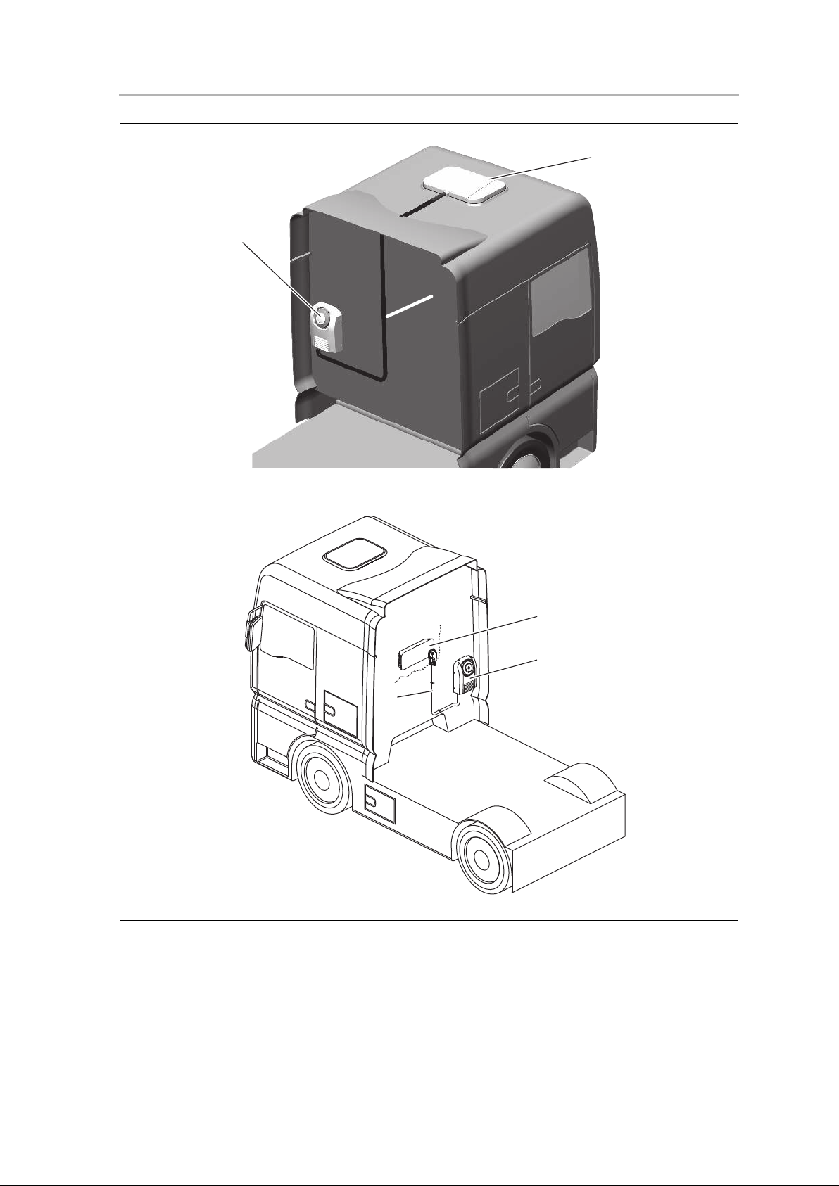
The compressor unit (fig. 1 1, page 3) is attached to the firm and straight rear
panel of the cab or by means of a firm fastening frame.
I
The SP950 auxiliary air conditioning unit with CoolAir SP950I rear panel
evaporator unit consists of the following components (fig. 1, page 3):
• CoolAir SP950C compressor unit (1)
• CoolAir SP950I rear panel evaporator unit (2) with connection line (3)
The SP950 auxiliary air conditioning unit with CoolAir SP950T roof evaporator
unit consists of the following components (fig. 1, page 3):
• CoolAir SP950C compressor unit (1)
• CoolAir SP950T roof evaporator unit (4) with connection line (3)
NOTICE!
The parking cooler may only be installed by qualified personnel from a
specialist company. The following information is intended for specialists who
are familiar with the guidelines and safety precautions to be applied.
NOTE
The connection line (fig. 1 3, page 3) can only be installed after fitting the
evaporator unit and the compressor unit.

13
EN
CoolAir SP950C Installation
6.2 Notes on installation
!
!
A
I
You should always read this installation manual all the way through before
installing the parking cooler.
WARNING! Danger of electrocution!
• Detach all connections to battery before starting installation of parking
cooler.
• Make sure that all electrical components are electrically discharged before
carrying out work on them!
CAUTION!
Improper installation of the air conditioning roof unit can result in irreparable
damage to the device and put the safety of the user at risk.
The manufacturer will not be held liable for claims if the air conditioning roof
unit is not installed according to this installation manual. That applies to malfunctions and the safety of the air conditioning roof unit, in particular to injuries
and damage to property.
NOTICE!
The manufacturer only assumes liability for parts included in the scope
of delivery. The validity of the warranty expires if the system is installed together
with third-party parts.
NOTE
• The manufacturer strongly recommends the use of a vehicle-specific
fastening frame for an optimum installation procedure for the CoolAir
SP950C compressor unit on the rear panel of the cab.
• After installing the unit, the specified parameters of the unit software must
be checked (refer to the installation instructions of the evaporator unit).

EN
Installation CoolAir SP950C
14
You should always observe the following tips and information when installing the
parking cooler:
• Please consult the manufacturer of your vehicle with regard to the following.
– is the cab's rear panel a suitable location for attaching the unit?
– is the body designed to bear the static weight and loads occasioned by
the parking cooler in a moving vehicle?
• Always check before installation of the unit whether any vehicle components
could be damaged, deformed or impaired in terms of their functionality as a
result of the installation.
• Avoid any unnecessary and frequent mechanical stress to the supply line
between the evaporator unit and the compressor unit. Damage can result in
the loss of refrigerant and impair the performance of the unit.
• The supplied assembly parts must not be modified during installation.
• The ventilation slots (grill) may not be covered (minimum distance from other
attachment parts: 10 cm).
• If a fastening frame is not used to install the system, make sure that the
installation position of the compressor unit on the rear panel is not too low.
The system could be damaged by high temperatures of the engine's waste
heat.
6.3 Determining the installation position
The installation position of the unit must meet the following criteria:
• All maintenance work must be easy to perform.
• Sufficient space must be available for the refrigerant line.
• The compressor unit must not be installed with a horizontal or vertical
inclination.
• The compressor unit must not be fitted near direct waste heat (engine heat
etc.).
• The refrigerant line (SP950T: approx. 4.2 m; SP950I: approx. 2.3 m) must
be long enough to connect the compressor and evaporator units. The line
must not be laid taut.
• The fastening surface should be as flat as possible. Use spacer sleeves for
uneven surfaces. If spacer sleeves are used, longer fastening screws with
sufficient tensile strength (not included in the assembly set) must be used.
• The freedom of movement of semi-trailers (of the outer edges of the semitrailer when turning or jackknifing) and other vehicle attachments must not be
restricted.

15
EN
CoolAir SP950C Installation
6.4 Installing the compressor unit
A
I
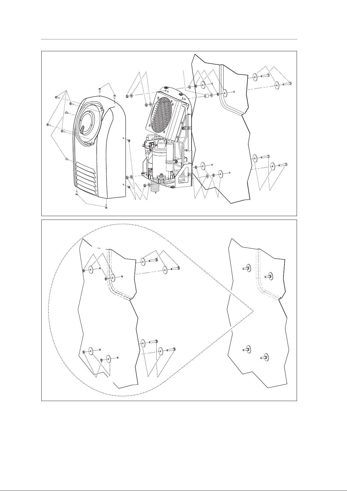
➤ Dismantle the outer housing.
To do this, remove the four hexagon bolts on the fan (fig. 2 1, page 4) and
the eight hexagon socket head bolts (fig. 2 2, page 4).
When taking off the outer housing, release the plug connection of the fan
connection cable.
➤ Decide on the position of the compressor unit.
Use the fastening holes of the compressor unit as a template.
➤ Use a felt pen to mark the positions selected for the holes.
➤ Drill fastening holes (Ø 9 mm) at the marked positions.
I
➤ Push the four M8 x 40 mm bolts (fig. 3 10,page 4) with the four washers
outer diameter Ø 40 mm (fig. 3 9,page 4) from the inside through the rear
wall.
➤ From the outside, push the four washers (fig. 3 8,page 4) on the protruding
bolts.
➤ Fasten the bolts and washers using the narrow M8 bolts (fig. 3 7, page 4).
➤ Push the washers (fig. 4 6, page 5) on the protruding M8 bolts.
For rear walls with an offset, use the supplied spacer sleeves (fig. 4 5,
page 5) to compensate.
Adjust the length.
➤ Put the compressor unit on the protruding M8 bolts.
➤ Fasten with the M8 washers (fig. 4 4, page 5) and the M8 lock nuts
(fig. 4 3, page 5).
NOTICE!
Due to its weight, the compressor unit must have contact with at least two
fastening points of the fastening surface. Do not use spacer sleeves for all four
fastening points.
NOTE
To install the compressor unit using a vehicle-specific fastening frame, please
observe the instructions included in the frame's scope of delivery. The
following work steps describe the installation of the compressor unit without
vehicle-specific fastening frame.
NOTE
Apply anti-oxidant compound to all drilled through-holes to prevent rust
formation.

EN
Installation CoolAir SP950C
16
I
6.5 Connecting the compressor unit to the evaporator
unit
A
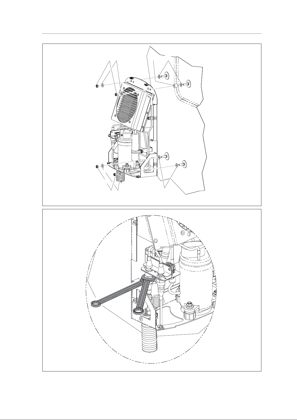
➤ Install the connection line for the compressor unit and insert it in the
compressor unit.
I
➤ Connect the rear coupling halves (thick refrigerant line) (fig. 5, page 5) with
each other and tighten them hand-tight ¼ revolution with an open-ended
spanner.
➤ Connect the front coupling halves (thin refrigerant line) (fig. 6, page 6) with
each other and tighten them hand-tight ¼ revolution with an open-ended
spanner.
➤ Install the protective cover underneath the coupling and secure it with the lid
supplied.
➤ Fasten the thick refrigerant line with the supplied pipe clip, the M6 x 16 mm
hexagon head bolt, the M6 U washer and the M6 retainer nuts (fig. 7,
page 6).
Observe the following instructions when installing the supply lines:
• Also observe the installation instructions for the evaporator unit.
• The maximum cable length between the evaporator and compressor unit is:
– SP950T: approx. 4.2 m
– SP950T: approx. 2.3 m
NOTE
The panelling can only be fitted once the refrigerant lines and the cables
(chapter “Connecting the compressor unit to the evaporator unit” on page 16)
have been connected.
NOTICE!
Before fastening the connection couplings, make sure that the sealing and
thread faces are absolutely clean. Any contamination will result in a malfunction
of the air conditioner.
NOTE
Make sure that the coupling half with the thin capillary tube is not twisted or
kinked.
When tightening the coupling halves, it is essential that you use a second openended spanner to hold the other part.

17
EN
CoolAir SP950C Installation
• Avoid any narrow radiuses when routing and bending supply lines. Use a
suitable round object with a shim as a bending aid. A radius which is too
narrow will kink the refrigerant line, and this will prevent the auxiliary air
conditioning unit from operating.
➤ Shorten any supply line which is not needed by bending a curve.
➤ Apply sealant (fig. 8 1, page 7) to prevent any water from getting between
the rear wall of the truck and the clip.
I
➤ Use the supplied holders to fasten the connection line to the rear panel of the
truck (fig. 8, page 7).
➤ Insert corrugated piping in the holder provided (fig. 8 2, page 7).
➤ Put on the lid (fig. 8 4, page 7).
➤ Insert the plug of the cable (power cable) into the mating plug of the
compressor unit (fig. 9, page 7).
➤ Insert the plug connection of the fan cable back together.
➤ Place the outer housing onto the compressor unit.
➤ Fasten the outer housing with the eight hexagon socket screws (fig. 2 2,
page 4).
➤ Fasten the fan with the four hexagon bolts (fig. 2 1, page 4).
NOTE
If you want to avoid damaging the rear wall of the truck (drilling a hole), you can
also apply the clip using a suitable adhesive.
Observe the instructions provided by the adhesive manufacturer.
EN
Technical data CoolAir SP950C
18
7 Technical data
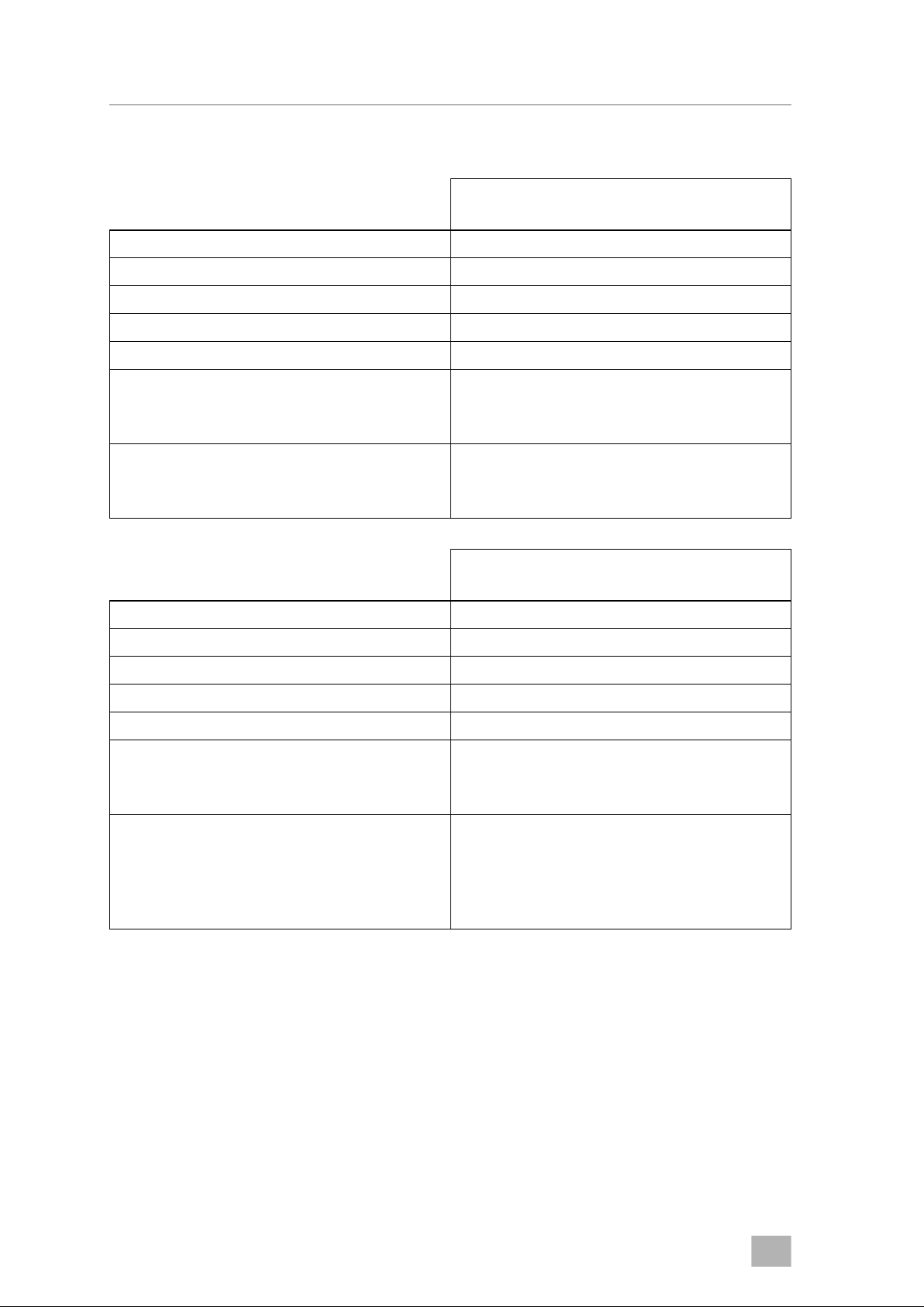
CoolAir SP950 parking cooler with
SP950T roof evaporator unit
Cooling capacity: 850 W
Voltage: 24 Vg (22.5 Ag – 30 Vg)
Max. current consumption: 22 A
Operating temperature range: 0 to +43 °C
Low voltage shutdown: Configurable
Dimensions (L x W x H):
Evaporator unit:
Compressor unit:
577 x 779 x 182 mm
156 x 346 x 490 mm
Wei ght :
Evaporator unit:
Compressor unit:
approx. 15 kg
approx. 12 kg
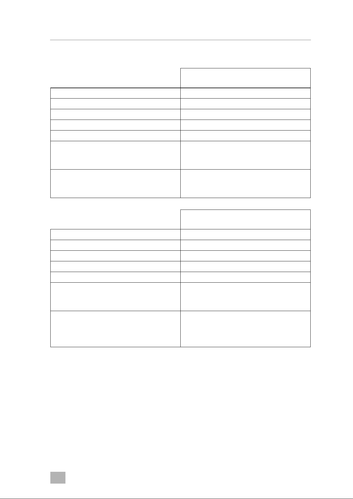
CoolAir SP 950 parking cooler with SP950I
rear panel evaporator unit
Cooling capacity: 850 W
Voltage: 24 Vg (22.5 Ag – 30 Vg)
Max. current consumption: 22 A
Operating temperature range: 0 to +43 °C
Low voltage shutdown: Configurable
Dimensions (W x H x D):
Evaporator unit:
Compressor unit:
648 x 278 x 144 mm
346 x 490 x 156 mm
Wei ght:
Evaporator unit
(including connection lines):
Compressor unit
(without fastening frame):
approx. 10,5 kg
approx. 12 kg

19
DE
CoolAir SP950C Erklärung der Symbole
Inhaltsverzeichnis
1 Erklärung der Symbole . . . . . . . . . . . . . . . . . . . . . . . . . . . . . . . . . 19
2 Sicherheitshinweise . . . . . . . . . . . . . . . . . . . . . . . . . . . . . . . . . . . . 20
2.1 Umgang mit dem Gerät . . . . . . . . . . . . . . . . . . . . . . . . . . . . . . . . . . . . . . . . . . . . 20
2.2 Umgang mit elektrischen Leitungen . . . . . . . . . . . . . . . . . . . . . . . . . . . . . . . . . . 21
3 Handbuchkonventionen . . . . . . . . . . . . . . . . . . . . . . . . . . . . . . . . 21
3.1 Allgemeine Informationen zur Einbauanleitung . . . . . . . . . . . . . . . . . . . . . . . . . 21
3.2 Zielgruppe . . . . . . . . . . . . . . . . . . . . . . . . . . . . . . . . . . . . . . . . . . . . . . . . . . . . . . 21
4 Bestimmungsgemäße Anwendung . . . . . . . . . . . . . . . . . . . . . . . 22
5 Lieferumfang. . . . . . . . . . . . . . . . . . . . . . . . . . . . . . . . . . . . . . . . . . 22
6 Installation. . . . . . . . . . . . . . . . . . . . . . . . . . . . . . . . . . . . . . . . . . . . 23
6.1 Vorgeschriebene Installationsweise . . . . . . . . . . . . . . . . . . . . . . . . . . . . . . . . . . 23
6.2 Hinweise zur Installation. . . . . . . . . . . . . . . . . . . . . . . . . . . . . . . . . . . . . . . . . . . . 24
6.3 Anbauposition bestimmen . . . . . . . . . . . . . . . . . . . . . . . . . . . . . . . . . . . . . . . . . 25
6.4 Kompressoreinheit anbauen . . . . . . . . . . . . . . . . . . . . . . . . . . . . . . . . . . . . . . . . 26
6.5 Kompressoreinheit mit Verdampfereinheit verbinden. . . . . . . . . . . . . . . . . . . . 27
7 Technische Daten . . . . . . . . . . . . . . . . . . . . . . . . . . . . . . . . . . . . . . 29
1 Erklärung der Symbole
!
!
A
I
WARNUNG!
Sicherheitshinweis: Nichtbeachtung kann zu Tod oder schwerer Verletzung
führen.
VORSICHT!
Sicherheitshinweis: Nichtbeachtung kann zu Verletzungen führen.
ACHTUNG!
Nichtbeachtung kann zu Materialschäden führen und die Funktion des
Produktes beeinträchtigen.
HINWEIS
Ergänzende Informationen zur Bedienung des Produktes.

DE
Sicherheitshinweise CoolAir SP950C
20
2 Sicherheitshinweise
Es ist zwingend notwendig, den gesamten Inhalt des Handbuches aufmerksam
zu lesen. Nur wenn den Anleitungen Folge geleistet wird, können Zuverlässigkeit der Klimaanlage und Schutz vor Personen oder Sachschäden gewährleistet
werden.
Der Hersteller übernimmt in folgenden Fällen keine Haftung für Schäden:
• Montage- oder Anschlussfehler
• Beschädigungen am Produkt durch mechanische Einflüsse und Über-
spannungen
• Veränderungen am Produkt ohne ausdrückliche Genehmigung vom
Hersteller
• Verwendung für andere als die in der Anleitung beschriebenen Zwecke
2.1 Umgang mit dem Gerät
• Die Bewegungsfreiheit von Aufliegern (die äußeren Kanten des Aufliegers
beim Einlenken oder Einknicken) und anderen Fahrzeuganbauten darf nicht
eingeschränkt werden.
• Benutzen Sie die Standklimaanlage nur für den vom Hersteller angegebenen
Verwendungszweck und führen Sie keine Änderungen oder Umbauten am
Gerät durch!
• Wenn die Standklimaanlage sichtbare Beschädigungen aufweist, darf Sie
nicht in Betrieb genommen werden.
• Die Standklimaanlage muss so sicher installiert werden, dass diese nicht
umstürzen oder herabfallen kann!
• Die Installation, Wartung und etwaige Reparatur dürfen nur durch einen
Fachbetrieb erfolgen, der mit den damit verbundenen Gefahren bzw. einschlägigen Vorschriften vertraut ist!
• Setzen Sie die Standklimaanlage nicht in der Nähe von entflammbaren
Flüssigkeiten und Gasen ein.
• Betreiben Sie die Standklimaanlage nicht bei Außentemperaturen unter
0 °C.
• Im Falle von Feuer lösen Sie nicht den oberen Deckel der Standklimaanlage,
sondern verwenden Sie zugelassene Löschmittel. Verwenden Sie kein
Wasser zum Löschen.
• Lösen Sie bei Arbeiten (Reinigung, Wartung usw.) an der Standklimaanlage
alle Verbindungen zur Stromversorgung!

21
DE
CoolAir SP950C Handbuchkonventionen
2.2 Umgang mit elektrischen Leitungen
• Müssen Leitungen durch scharfkantige Wände geführt werden, so
verwenden Sie Leerrohre bzw. Leitungsdurchführungen!
• Verlegen Sie keine losen oder scharf abgeknickten Leitungen an elektrisch
leitenden Materialien (Metall)!
• Ziehen Sie nicht an Leitungen!
• Befestigen und verlegen Sie Leitungen so, dass keine Stolpergefahr entsteht
und eine Beschädigung des Kabels ausgeschlossen ist.
• Der elektrische Anschluss darf nur von einem Fachbetrieb durchgeführt
werden.
• Sichern Sie den Anschluss ans Netz im Fahrzeug mit 25 Ampere ab.
• Verlegen Sie niemals die Spannungsversorgungsleitung (Batteriekabel) in
räumlicher Nähe zu Signal- oder Steuerleitungen.
3 Handbuchkonventionen
3.1 Allgemeine Informationen zur Einbauanleitung
Diese Einbauanleitung enthält die wesentlichen Informationen und Anleitungen
für die Installation der Klimaanlage. Die enthaltenen Informationen richten sich
an den Installationsbetrieb der Klimaanlage.
Folgende Hinweise helfen Ihnen bei der korrekten Anwendung der
Einbauanleitung:
• Die Einbauanleitung ist Teil des Lieferumfangs und ist sorgfältig aufzubewahren.
• Die Einbauanleitung gibt Ihnen wichtige Hinweise für die Montage und dient
gleichzeitig in Reparaturfällen als Nachschlagewerk.
• Bei Nichtbeachtung dieser Einbauanleitung haftet der Hersteller nicht.
Jegliche Ansprüche sind für diesen Fall ausgeschlossen.
3.2 Zielgruppe
Die Einbauinformationen in dieser Anleitung wenden sich ausschließlich an
Fachleute in Werkstätten, die mit den anzuwendenden Richtlinien und
Sicherheitsvorkehrungen beim Einbau von Fahrzeugzubehörteilen vertraut sind.

DE
Bestimmungsgemäße Anwendung CoolAir SP950C
22
4 Bestimmungsgemäße Anwendung
Die Standklimaanlage CoolAir SP950 dient dazu, das Fahrerhaus eines LKW mit
gekühlter und entfeuchteter Luft zu klimatisieren. Der Einsatz während der Fahrt
ist möglich.
Die Kompressoreinheit CoolAir SP950C (Art.-Nr. 9100100033) ist nur in
Verbindung mit einer Dachverdampfereinheit CoolAir SP950T oder einer
Rückwandverdampfereinheit CoolAir SP950I funktionsfähig. Beide
Komponenten zusammen bilden die Standklimaanlage CoolAir SP950.
A
I
Die CoolAir SP950 wird Ihnen in einem installationsfähigen Zustand geliefert.
Der Hersteller empfiehlt ausdrücklich die Verwendung eines fahrzeugspezifischen Befestigungsrahmens zur optimalen Montage der Kompressoreinheit
CoolAir SP950C an die Fahrerhausrückwand.
5 Lieferumfang
ACHTUNG!
• Die Standklimaanlage SP950 ist nicht für die Installation in Land- und Baumaschinen oder ähnlichen Arbeitsgeräten geeignet. Bei zu starker
Vibrations- und Staubeinwirkung ist eine ordnungsgemäße Funktion nicht
gewährleistet.
• Der Betrieb der Standklimaanlage SP950 mit Spannungswerten, die von
den angegebenen Werten abweichen, führt zur Beschädigung des
Gerätes.
HINWEIS
Die Standklimaanlage SP950 ist für eine Umgebungstemperatur nicht über
43 °C im Kühlbetrieb ausgelegt.
Teilebezeichnung Menge Art.-Nr.
CoolAir SP950C Kompressoreinheit 1 9100100033
Universal-Einbausatz 1 –
Einbauanleitung 1 4445100626

23
DE
CoolAir SP950C Installation
6 Installation
A
6.1 Vorgeschriebene Installationsweise
Die Kompressoreinheit (fig. 1 1, page 3) wird an der stabilen und geraden
Fahrerhausrückwand oder unter Verwendung eines stabilen Befestigungsrahmen angebracht.
I
Die Standklimaanlage SP950 mit Rückwandverdampfereinheit CoolAir SP950I
besteht aus folgenden Komponenten (fig. 1, page 3):
• Kompressoreinheit CoolAir SP950C (1)
• Rückwandverdampfereinheit CoolAir SP950I (2) mit Verbindungsleitung (3)
Die Standklimaanlage SP950 mit Dachverdampfereinheit CoolAir SP950T
besteht aus folgenden Komponenten (fig. 1, page 3):
• Kompressoreinheit CoolAir SP950C (1)
• Dachverdampfereinheit CoolAir SP950T (4) mit Verbindungsleitung (3)
ACHTUNG!
Die Installation der Klimaanlage darf ausschließlich von entsprechend
ausgebildeten Fachbetrieben durchgeführt werden. Die nachfolgenden
Informationen richten sich an Fachkräfte, die mit den anzuwendenden
Richtlinien und Sicherheitsvorkehrungen vertraut sind.
HINWEIS
Die Verbindungsleitung (fig. 1 3, page 3) kann erst nach Montage der
Verdampfereinheit und der Kompressoreinheit installiert werden.

DE
Installation CoolAir SP950C
24
6.2 Hinweise zur Installation
!
!
A
I
Lesen Sie unbedingt vor der Installation der Standklimaanlage diese Einbauanleitung vollständig durch.
Beachten Sie unbedingt folgende Tipps und Hinweise bei der Installation der
Standklimaanlage:
• Informieren Sie sich bei Ihrem Fahrzeughersteller:
– Ist die Fahrerhausrückwand für das Anbringen der Anlage geeignet?
– Ist der Aufbau für das statische Gewicht und die Belastungen durch die
Standklimaanlage bei sich bewegendem Fahrzeug ausgelegt?
• Prüfen Sie vor der Installation der Anlage, ob durch den Einbau Fahrzeugkomponenten beschädigt, verformt oder in ihrer Funktion beeinträchtigt
werden könnten.
• Vermeiden Sie unnötige und häufige mechanische Beanspruchungen der
Versorgungsleitung zwischen Verdampfer- und Kompressoreinheit.
Beschädigungen können zu Kältemittelverlust und zu einer Beeinträchtigung
der Anlagenleistung führen.
WARNUNG! Gefahr durch Stromschlag!
• Lösen Sie vor der Installation der Standklimaanlage alle Verbindungen zur
Batterie.
• Stellen Sie vor Arbeiten an elektrisch betriebenen Komponenten sicher,
dass keine Spannung mehr anliegt.
VORSICHT!
Eine falsche Installation der Standklimaanlage kann zu irreparablen Schäden
am Gerät führen und die Sicherheit des Benutzers beeinträchtigen.
Wenn die Standklimaanlage nicht gemäß dieser Einbauanleitung installiert
wird, übernimmt der Hersteller keinerlei Haftung. Nicht für Betriebsstörungen
und für die Sicherheit der Standklimaanlage, insbesondere nicht für Personenund/oder Sachschäden.
ACHTUNG!
Der Hersteller übernimmt ausschließlich Haftung für im Lieferumfang
enthaltene Teile. Beim Einbau der Anlage zusammen mit produktfremden
Teilen entfallen die Gewährleistungsansprüche.
HINWEIS
• Der Hersteller empfiehlt ausdrücklich die Verwendung eines fahrzeugspezifischen Befestigungsrahmens zur optimalen Montage der
Kompressoreinheit SP950C an die Fahrerhausrückwand.
• Nach der Installation der Anlage müssen die vorgegebenen Parameter der
Anlagen-Software überprüft werden (siehe Installationsanleitung der zugehörigen Verdampfereinheit).

25
DE
CoolAir SP950C Installation
• Die mitgelieferten Montageteile dürfen beim Einbau nicht eigenmächtig
modifiziert werden.
• Die Lüftungsöffnungen (Gitter) dürfen nicht abgedeckt werden (Mindestabstand zu anderen Anbauteilen: 10 cm).
• Wird die Anlage nicht mit einem Befestigungsrahmen eingebaut, so achten
Sie darauf, dass die Einbauposition der Kompressoreinheit nicht zu tief an der
Rückwand gewählt wird. Durch die hohen Temperaturen der Motorabwärme kann die Anlage beschädigt werden.
6.3 Anbauposition bestimmen
Die Anbauposition der Anlage muss folgende Kriterien erfüllen:
• Wartungsarbeiten müssen leicht durchgeführt werden können.
• Für die Kältemittelleitung muss genügend Platz vorhanden sein.
• Die Kompressoreinheit darf nicht in Horizontal- und Vertikalrichtung geneigt
eingebaut werden.
• Die Kompressoreinheit darf nicht im Bereich von direkter Abwärme (Motorwärme usw.) montiert werden.
• Die Länge der Kältemittelleitung (SP950T: ca. 4,2 m; SP950I: ca. 2,3 m)
muss zur Verbindung der Kompressor- und Verdampfereinheit ausreichen.
Die Leitung darf nicht auf Spannung verlegt werden.
• Die Befestigungsfläche sollte möglichst eben sein. Bei unebenen Flächen
müssen Distanzhülsen verwendet werden. Bei Verwendung von Distanzhülsen müssen entsprechend längere Befestigungsschrauben mit ausreichender Zugfestigkeit (nicht im Montagesatz vorhanden) verwandt werden.
• Die Bewegungsfreiheit von Aufliegern (die äußeren Kanten des Aufliegers
beim Einlenken oder Einknicken) und anderen Fahrzeuganbauten darf nicht
eingeschränkt werden.

DE
Installation CoolAir SP950C
26
6.4 Kompressoreinheit anbauen
A
I
➤ Außengehäuse demontieren.
Hierzu die vier Sechskantschrauben am Lüfter (fig. 2 1, page 4) und die
acht Innensechskant-Schrauben (fig. 2 2, page 4) entfernen.
Beim Abziehen des Außengehäuses die Steckverbindung des Lüfteranschlusskabels lösen.
➤ Position der Kompressoreinheit ermitteln.
Hierzu die Befestigungslöcher der Kompressoreinheit als Schablone
benutzen.
➤ Gewählte Bohrungen mit einem Filzstift anzeichnen.
➤ Befestigungslöcher (Ø 9 mm) an den angezeichneten Stellen bohren.
I
➤ Die vier Schrauben M8 x 40 mm (fig. 3 10, page 4) mit den vier Unterleg-
scheiben AD Ø 40 mm (fig. 3 9, page 4) von innen durch die Rückwand
schieben.
➤ Von außen die vier Unterlegscheiben (fig. 3 8, page 4) auf die heraus-
ragenden Schrauben schieben.
➤ Diese Schrauben-Unterlegscheiben-Einheit mit den schmalen M8-Muttern
(fig. 3 7, page 4) festschrauben.
➤ Die Scheiben (fig. 4 6, page 5) auf die herausragenden M8-Schrauben
schieben.
Bei Rückwänden mit Versatz als Ausgleich die beigelegten Distanzhülsen
(fig. 4 5, page 5) benutzen.
Länge anpassen.
➤ Die Kompressoreinheit auf die herausragenden M8-Schrauben schieben.
➤ Mit den Unterlegscheiben M8 (fig. 4 4, page 5) und den Sicherungs-
muttern M8 (fig. 4 3, page 5) befestigen.
ACHTUNG!
Aufgrund des Gewichts muss die Kompressoreinheit an mindestens zwei
Befestigungspunkten der Befestigungsfläche anliegen. Verwenden Sie nicht
an allen vier Befestigungspunkten Distanzhülsen.
HINWEIS
Zum Anbau der Kompressoreinheit mit Hilfe eines fahrzeugspezifischen
Befestigungsrahmens beachten Sie die Anleitung im Lieferumfang des
Rahmens. Die nachfolgenden Arbeitsschritte beschreiben den Anbau der
Kompressoreinheit ohne fahrzeugspezifischen Befestigungsrahmen.
HINWEIS
Tragen Sie Oxidationsschutz um alle gebohrten durchgehenden Löcher auf,
um Rost zu vermeiden.

27
DE
CoolAir SP950C Installation
I
6.5 Kompressoreinheit mit Verdampfereinheit
verbinden
A
➤ Die Verbindungsleitung zur Kompressoreinheit verlegen und diese in die
Kompressoreinheit einführen.
I
➤ Die hinteren Kupplungshälften (dicke Kältemittelleitung) (fig. 5, page 5)
miteinander verbinden und mit einem Gabelschlüssel handfest +¼
Umdrehung anziehen.
➤ Die vorderen Kupplungshälften (dünne Kältemittelleitung) (fig. 6, page 6)
miteinander verbinden und mit einem Gabelschlüssel handfest +¼
Umdrehung anziehen.
➤ Die Schutzhülle in die Halterung, unterhalb der Kupplung, einsetzen und mit
dem beiliegenden Deckel fixieren.
➤ Die dicke Kältemittelleitung mit der beigelegten Rohrschelle, der Sechskant-
schraube M6 x 16 mm, der U-Scheibe M6 und der Sicherungsmutter M6
(fig. 7, page 6) fixieren.
Beachten Sie folgende Hinweise beim Verlegen der Versorgungsleitungen:
• Beachten Sie die Anbauanleitung der Verdampfereinheit.
• Die maximale Verlegungslänge zwischen Verdampfer- und Kompressor-
einheit beträgt:
– SP950T: ca. 4,2 m
– SP950I: ca. 2,3 m
HINWEIS
Die Verkleidung kann erst nach Anschluss der Kältemittelleitungen und der
Kabel (chapter “Kompressoreinheit mit Verdampfereinheit verbinden” on
page 27) angebracht werden.
ACHTUNG!
Achten Sie vor dem Verschrauben der Verbindungskupplungen auf absolute
Sauberkeit der Dicht- und Gewindeflächen. Eine Verunreinigung führt zur
Störung der Klimaanlage.
HINWEIS
Achten Sie darauf, dass die Kupplungshälfte mit der dünne Kapillarrohrleitung
nicht verdreht oder geknickt wird.
Benutzen Sie beim Festziehen der Kupplungshälften unbedingt einen zweiten
Gabelschlüssel zum Gegenhalten.

DE
Installation CoolAir SP950C
28
• Vermeiden Sie beim Verlegen und Biegen von Versorgungsleitungen enge
Radien. Benutzen Sie zum Biegen einen passenden Rundkörper den Sie
unterlegen. Bei einem zu engen Radius wird die Kältemittelleitung geknickt,
und die Standklimaanlage ist nicht betriebsbereit.
➤ Die nicht benötige Länge der Versorgungsleitung durch Biegen eines
Bogens kürzen.
➤ Dichtmasse aufbringen (fig. 8 1, page 7), um einen Wassereintritt zwischen
LKW-Rückwand und Clip zu verhindern.
I
➤ Versorgungsleitung mit den beiliegenden Clips auf der LKW-Rückwand
(fig. 8, page 7) befestigen.
➤ Wellrohr in die vorgesehene Halterung (fig. 8 2, page 7) stecken.
➤ Deckel (fig. 8 4, page 7) einsetzen.
➤ Kabel mit dem Stecker (Versorgungsleitung) in den Gegenstecker der
Kompressoreinheit (fig. 9, page 7) stecken.
➤ Steckverbindung des Lüfterkabel wieder zusammenstecken.
➤ Außengehäuse auf die Kompressoreinheit schieben.
➤ Außengehäuse mit den acht Innensechskant-Schrauben (fig. 2 2, page 4)
festschrauben.
➤ Lüfter mit den vier Sechskantschrauben (fig. 2 1, page 4) festschrauben.
HINWEIS
Wenn Sie eine Beschädigung der LKW-Rückwand (Bohrung) vermeiden
möchten, können Sie den Clip auch mit einem geeigneten Kleber aufkleben.
Beachten Sie die Hinweise des Klebstoffherstellers.
29
DE
CoolAir SP950C Technische Daten
7 Technische Daten
Standklimaanlage CoolAir SP950
mit Dachverdampfereinheit SP950T
Max. Kühlleistung: 850 W
Anschlussspannung: 24 Vg (22,5 Ag – 30 Vg)
Max. Stromverbrauch: 22 A
Betriebstemperaturbereich: 0 bis +43 °C
Unterspannungsabschaltung: konfigurierbar
Abmessungen (L x B x H):
Verdampfereinheit:
Kompressoreinheit:
577 x 779 x 182 mm
156 x 346 x 490 mm
Gewicht:
Verdampfereinheit:
Kompressoreinheit:
ca. 15 kg
ca. 12 kg
Standklimaanlage CoolAir SP950
mit Rückwandverdampfereinheit SP950I
Max. Kühlleistung: 850 W
Anschlussspannung: 24 Vg (22,5 Ag – 30 Vg)
Max. Stromverbrauch: 22 A
Betriebstemperaturbereich: 0 bis +43 °C
Unterspannungsabschaltung: konfigurierbar
Maße (B x H x T):
Verdampfereinheit:
Kompressoreinheit:
648 x 278 x 144 mm
346 x 490 x 156 mm
Gewicht
Verdampfereinheit
(einschließlich Anschlussleitungen):
Kompressoreinheit (ohne Befestigungsrahmen):
ca. 10,5 kg
ca. 12 kg

FR
Explication des symboles CoolAir SP950C
30
Sommaire
1 Explication des symboles. . . . . . . . . . . . . . . . . . . . . . . . . . . . . . . . 30
2 Consignes de sécurité. . . . . . . . . . . . . . . . . . . . . . . . . . . . . . . . . . . 31
2.1 Précautions d'usage . . . . . . . . . . . . . . . . . . . . . . . . . . . . . . . . . . . . . . . . . . . . . . .31
2.2 Précautions concernant les lignes électriques . . . . . . . . . . . . . . . . . . . . . . . . . . 32
3 Conventions du manuel . . . . . . . . . . . . . . . . . . . . . . . . . . . . . . . . . 32
3.1 Informations générales concernant la notice d'installation . . . . . . . . . . . . . . . . 32
3.2 Groupe cible . . . . . . . . . . . . . . . . . . . . . . . . . . . . . . . . . . . . . . . . . . . . . . . . . . . . 32
4 Usage conforme . . . . . . . . . . . . . . . . . . . . . . . . . . . . . . . . . . . . . . . 33
5 Pièces fournies. . . . . . . . . . . . . . . . . . . . . . . . . . . . . . . . . . . . . . . . . 33
6 Installation . . . . . . . . . . . . . . . . . . . . . . . . . . . . . . . . . . . . . . . . . . . . 34
6.1 Méthode d'installation prescrite. . . . . . . . . . . . . . . . . . . . . . . . . . . . . . . . . . . . . 34
6.2 Consignes de sécurité concernant l'installation. . . . . . . . . . . . . . . . . . . . . . . . . 35
6.3 Choix de la position de montage . . . . . . . . . . . . . . . . . . . . . . . . . . . . . . . . . . . . 36
6.4 Montage de l'unité du compresseur . . . . . . . . . . . . . . . . . . . . . . . . . . . . . . . . . 37
6.5 Raccordement du compresseur à l'évaporateur . . . . . . . . . . . . . . . . . . . . . . . . 38
7 Caractéristiques techniques . . . . . . . . . . . . . . . . . . . . . . . . . . . . . 40
1 Explication des symboles
!
!
A
I
AVERTISSEMENT !
Consigne de sécurité : le non-respect de ces consignes peut entraîner la
mort ou de graves blessures.
ATTENTION !
Consigne de sécurité : le non-respect de ces consignes peut entraîner des
blessures.
AVIS !
Le non-respect de ces consignes peut entraîner des dommages matériels et
des dysfonctionnements du produit.
REMARQUE
Informations complémentaires sur l'utilisation du produit.
 Loading...