

Page 1
CK500
EN
DEFRES
PT
IT
NLDASVNOFIRUPLSKCS
HU
Extractor hood
Installation and Operating Manual. . . . . . . .8
Dunstabzugshaube
Montage- und Bedienungsanleitung . . . . . 19
Hotte d'aspiration
Instructions de montage
et de service . . . . . . . . . . . . . . . . . . . . . . . . .30
COOKING
RANGE HOODS
Avtrekkshette
Monterings- og bruksanvisning. . . . . . . . 106
Liesituuletin
Asennus- ja käyttöohje . . . . . . . . . . . . . . . 117
Отводящая вытяжка
Инструкция по монтажу и эксплуатации 128
Okap kuchenny
Instrukcja montażu i obsługi. . . . . . . . . . . 139
Odsávač pár
Návod na montáž a uvedenie
do prevádzky. . . . . . . . . . . . . . . . . . . . . . . 150
Odsavač par
Návod k montáži a obsluze . . . . . . . . . . . 161
Páraelszívó
Szerelési és használati útmutató . . . . . . . 172
Extractor de humos
Instrucciones de montaje y de uso. . . . . . . 41
Exaustor
Instruções de montagem e manual de
instruções . . . . . . . . . . . . . . . . . . . . . . . . . . .52
Cappa aspirante
Istruzioni di montaggio e d’uso . . . . . . . . .63
Afzuigkap
Montagehandleiding en
gebruiksaanwijzing . . . . . . . . . . . . . . . . . . .74
Emhætte
Monterings- og betjeningsvejledning . . . .85
Spisfläkt
Monterings- och bruksanvisning . . . . . . . .96
Page 2
Page 3
CK500
1
2
3
4
5 6
1
1 2 3 4 5 6 7
2
21
3
3
Page 4
CK500
1
4
A B
5
4
Page 5
CK500
234,5
189,5
6
2
1
7
5
Page 6

8
Ø 75-80
ø110
1.
2.
9
CK500
6
Page 7
CK500
0
a
1.
2.
7
Page 8

EN
CK500
Please read this instruction manual carefully before installation and first
use, and store it in a safe place. If you pass on the product to another
person, hand over this instruction manual along with it.
Contents
1 Explanation of symbols. . . . . . . . . . . . . . . . . . . . . . . . . . . . . . . . . . . . . . . . . . .9
2 Safety instructions . . . . . . . . . . . . . . . . . . . . . . . . . . . . . . . . . . . . . . . . . . . . . . .9
3 Scope of delivery . . . . . . . . . . . . . . . . . . . . . . . . . . . . . . . . . . . . . . . . . . . . . . 11
4 Intended use . . . . . . . . . . . . . . . . . . . . . . . . . . . . . . . . . . . . . . . . . . . . . . . . . . 11
5 Technical description . . . . . . . . . . . . . . . . . . . . . . . . . . . . . . . . . . . . . . . . . . . 11
6 Installing the device . . . . . . . . . . . . . . . . . . . . . . . . . . . . . . . . . . . . . . . . . . . .13
7 Operating the device . . . . . . . . . . . . . . . . . . . . . . . . . . . . . . . . . . . . . . . . . . .16
8 Cleaning . . . . . . . . . . . . . . . . . . . . . . . . . . . . . . . . . . . . . . . . . . . . . . . . . . . . .17
9 Disposal . . . . . . . . . . . . . . . . . . . . . . . . . . . . . . . . . . . . . . . . . . . . . . . . . . . . . .17
10 Warranty . . . . . . . . . . . . . . . . . . . . . . . . . . . . . . . . . . . . . . . . . . . . . . . . . . . . .18
11 Technical data . . . . . . . . . . . . . . . . . . . . . . . . . . . . . . . . . . . . . . . . . . . . . . . . .18
8
Page 9
EN
CK500 Explanation of symbols
1 Explanation of symbols
WARNING!
!
Safety instruction: Failure to observe this instruction can cause fatal or
serious injury.
CAUTION!
Safety instruction: Failure to observe this instruction can lead to injury.
!
NOTICE!
A
Failure to observe this instruction can cause material damage and impair
the function of the product.
NOTE
Supplementary information for operating the product.
I
2 Safety instructions
Please observe the prescribed safety instructions and stipulations from the
vehicle manufacturer and service workshops.
The manufacturer accepts no liability for damage in the following cases:
• Faulty assembly or connection
• Damage to the product resulting from mechanical influences and excess voltage
• Alterations to the product without express permission from the manufacturer
• Use for purposes other than those described in the operating manual
Note the following basic safety information when using electrical devices to protect
against:
• Electric shock
• Fire hazards
• Injury
9
Page 10

EN
Safety instructions CK500
2.1 Handling the device
WARNING!
!
• Installation and repair of the extractor hood may only be
carried out by qualified personnel who are familiar with the
risks involved and the relevant regulations.
• Inadequate repairs may cause serious hazards. For repair service,
please contact the service centre in your country
(addresses on the back page of the manual).
• This device can be used by children aged 8 years or over, as well as by
persons with diminished physical, sensory or mental capacities or a
lack of experience and knowledge, providing they are supervised, or
have been taught how to use the device safely and are aware of the
resulting risks.
• Installation work and electrical connection must be performed by
skilled technicians in compliance with all applicable regulations and
standards.
• When cutting or drilling into walls or ceilings, make sure that no
electrical cables or hidden devices are damaged.
• The distance between the gas hob flame and the extractor hood must
be at least 50 cm.
!
CAUTION!
• The extractor hood must be installed securely so that it cannot fall
down.
• Only operate the extractor hood if you are certain that the housing and
the cables are not damaged.
• Do not insert foreign objects into the device.
10
Page 11
EN
CK500 Scope of delivery
3Scope of delivery
No. in
fig. 1,
page 3
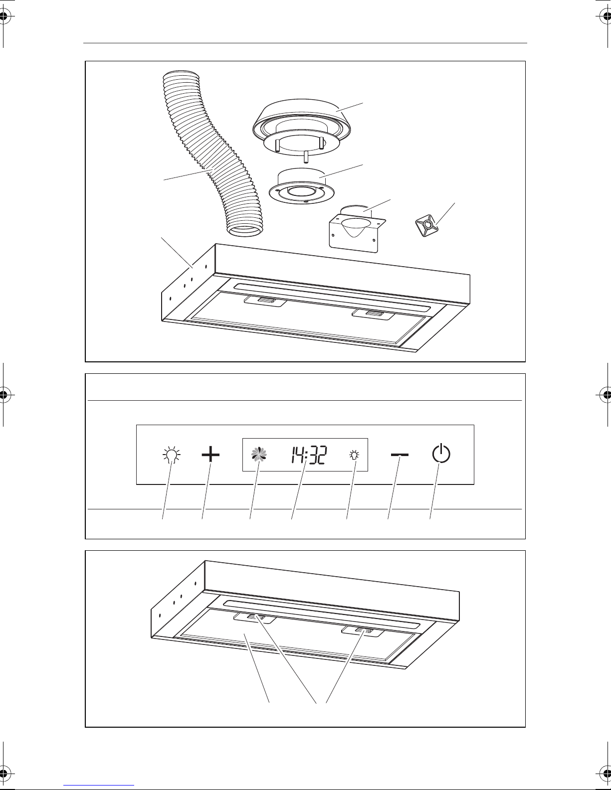
1 1 CK500 extractor hood
2 1 Air outlet hose
3 1 Upper part of the mushroom vent
4 1 Lower part of the mushroom vent
5 1 Air outlet adapter
6 3 Adhesive socket
– 5 Cable binders
Quantity Description
4 Intended use
The CK500 extractor hood (ref. no. 9106506287) is designed for installation in
recreational vehicles such as caravans, motorhomes and boats.
5 Technical description
The CK500 extractor hood removes odours and steam that occurs during cooking.
Its filter is detachable and washable.
The CK500 features an LED light, two fans and a touch display.
The outlet air can be discharged upwards or to the rear.
11
Page 12
EN
Technical description CK500
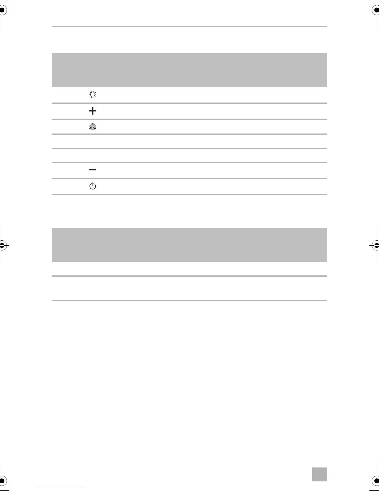
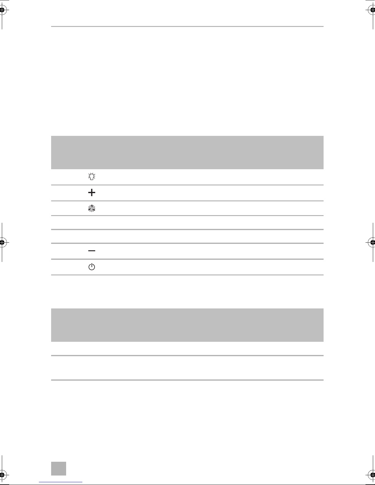
5.1 Control elements
No. in
fig. 2,
page 3
1 Switches the light on and off
2 Increases the fan speed and sets the time
3 Displays the fan speed
4 Displays the time
5 Lights up when the light is switched on
6 Decreases the fan speed and sets the time
7 Switches the extractor hood on and off
Description
5.2 Filter
No. in
fig. 3,
page 3
1 Filter
2 Lock
Description
Push to the rear: unlock and remove the filter
12
Page 13

EN
CK500 Installing the device
6 Installing the device
WARNING!
!
A
I
The distance between the gas hob flame and the extractor hood must
be at least 50 cm.
NOTICE!
Make sure when you are planning the location of the air outlet guide that
there are no electrical cables or vehicle parts in the vicinity, such as a roof
rack. Otherwise they might be damaged when drilling.
NOTE
• This section describes how to discharge the outlet air upwards.
• The outlet air can also be discharged to the side. Additional
accessories are necessary to do this. In this case have the extractor
hood installed at an authorised workshop.
6.1 Notes on the installation position
• It is best to install the extractor hood in the middle of the cooking area and
integrate it into a wall-mounted cupboard, where possible.
• The distance between the gas hob flame and the extractor hood must be at least
50 cm.
• The outlet air can be discharged upwards or to the side.
If the outlet air is to be discharged to the side, an additional fan (not included)
must be used.
• Prior to installation it must be clarified how the air outlet hose will be installed and
where the mushroom vent can be installed (fig. 4, page 4).
When doing so, note any cupboard dividing walls and shelves.
The holes for the air outlet hose must be positioned so that no electrical cables in
the structure, no supporting structures or vehicle parts, such as roof racks, are
affected.
13
Page 14

EN
Installing the device CK500
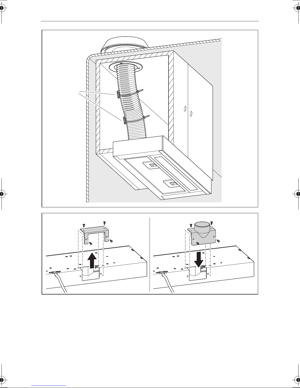
6.2 Preparing the air outlet guide
Installing the air outlet adapter
➤ Remove the air outlet connection cover (fig. 5 A, page 4).
➤ Install the air outlet adapter (fig. 5 B, page 4).
Preparing the wall-mounted cupboard
➤ Mark the middle of the hole for the air outlet hose on the wall-mounted cupboard
(fig. 6, page 5).
➤ Drill a hole in the bottom of the wall-mounted cupboard with a diameter of
75 – 80 mm.
Preparing the roof outlet
A hole must be made in a suitable place in the roof for the air outlet hose with a
diameter of 110 mm (fig. 4, page 4).
Proceed in the following way so that the roof does not come out:
➤ Firstly, using a small drill from the inside (diameter 3 – 5 mm) drill a hole through
the roof.
➤ Drill the hole from above with a diameter of 110 mm up to 2/3 of the roof
thickness.
➤ Drill all the way through the roof from below.
14
Page 15

EN
CK500 Installing the device
6.3 Installing and connecting the extractor hood
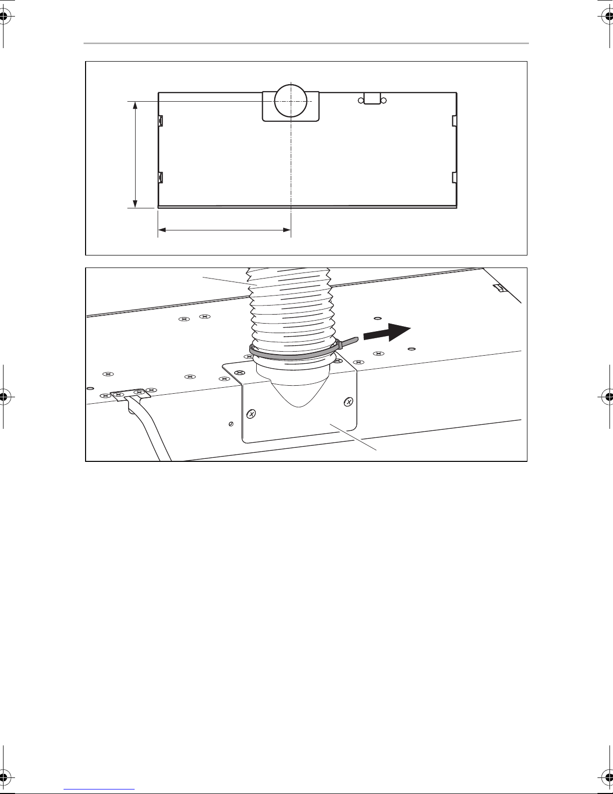
➤ Push the air outlet hose (fig. 7 1, page 5) on the air outlet adapter into the
extractor hood (fig. 7 2, page 5).
➤ Fix the air outlet hose onto the air outlet adapter with a cable binder.
➤ Remove the filter.
➤ Lift the extractor hood into the required position and guide the air outlet hose
and the connection cable through the hole in the wall-mounted cupboard.
➤ Secure the extractor hood with four screws (fig. 8, page 6).
To do this, use screws with the following size:
–Diameter 4mm
– Length according to the thickness of the wall-mounted cupboard
➤ Replace the filter.
➤ Connect the connection cable to the DC power supply.
Make sure the polarity is correct.
6.4 Completing the air outlet guide
➤ Lubricate and clean the area around the roof opening.
➤ Apply the upper part of the mushroom vent with a permanently elastic sealing
material (e.g. Dekalin) (fig. 9, page 6).
➤ Place the upper part of the mushroom vent into the roof opening.
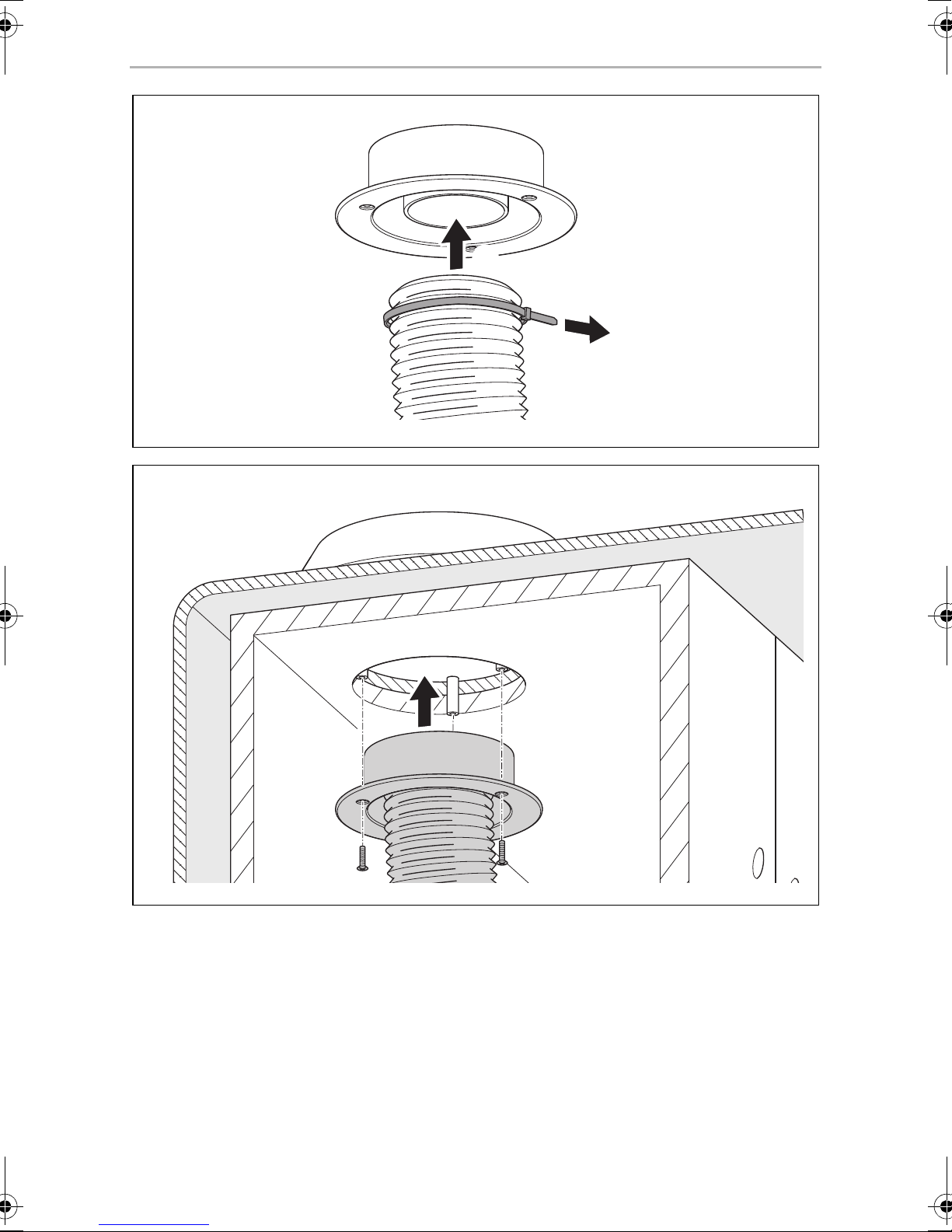
➤ Push the air outlet hose onto the lower part of the mushroom vent (fig. 0,
page 7).
➤ Fix the air outlet hose onto the lower part of the mushroom vent with a cable
binder.
➤ Push the lower part of the mushroom vent into upper part (fig. a, page 7) from
the inside.
➤ Secure the lower part of the mushroom vent with three screws.
To do this, use screws with the following size:
–Diameter 4mm
– Length = roof thickness – 10 mm
➤ Fix the air outlet hose with the adhesive socket (fig. 4 1, page 4) and cable
binders at suitable places.
15
Page 16
EN
Operating the device CK500
7 Operating the device
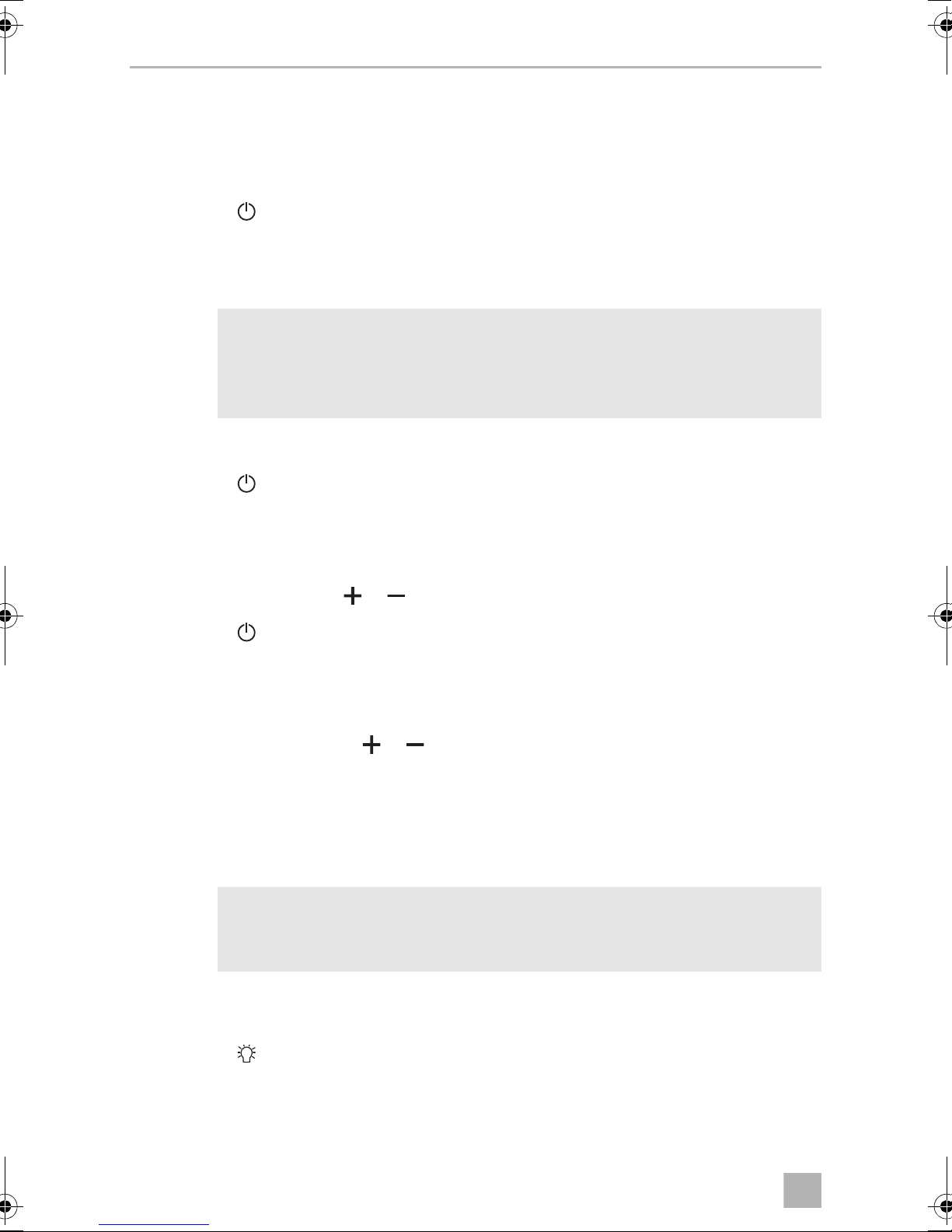
7.1 Switching the extractor hood on and off
➤ Press the button to switch the extractor hood on or off.
7.2 Setting the time
NOTE
I
➤ Switch on the extractor hood.
➤ Press the button for three seconds to set the hours.
• When the extractor hood is connected to the power supply, the
display shows 00:00.
• After three seconds without any entries, the settings are saved.
✓ A confirmation signal is emitted.
✓ All the digits on the clock flash.
➤ Set the hours with the or button.
➤ Press the button for three seconds to set the minutes.
✓ A confirmation signal is emitted.
✓ All the digits on the clock flash.
➤ Set the minutes with the or button.
➤ Wait three seconds.
✓ The digits on the clock light up permanently.
✓ The new time setting is saved.
NOTE
I
In the time between 8 pm and 6 am, the display on the clock disappears
after 5 minutes if none of the buttons have been pressed.
7.3 Switching the light on and off
➤ Press the button to switch the light on and off.
16
Page 17
EN
CK500 Cleaning
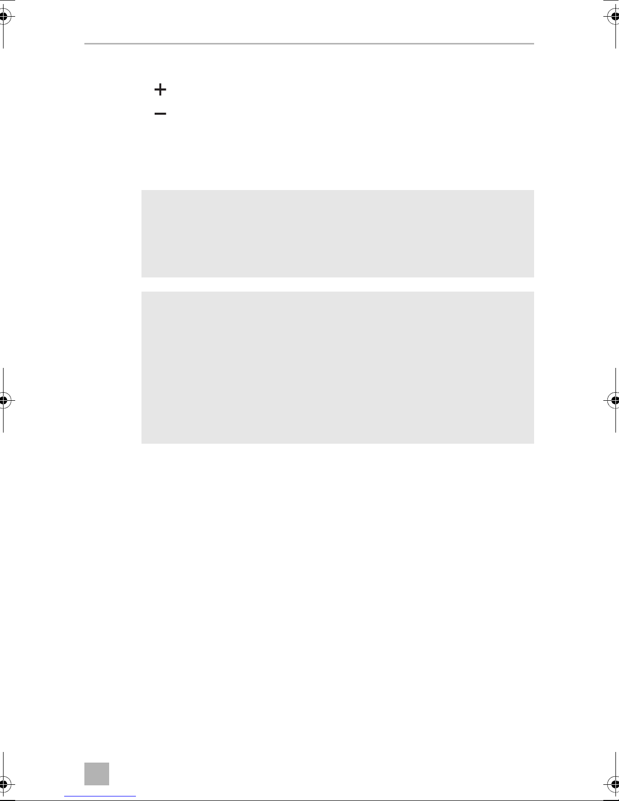
7.4 Setting the fan speed
➤ Press the button to increase the fan speed.
➤ Press the button to decrease the fan speed.
8Cleaning
NOTICE!
A
I
• Do not use sharp or hard objects or cleaning agents for cleaning as
these may damage the product.
• Do not clean the electronic components of the extractor hood with
water or a wet cloth.
NOTE
• The filter of the extractor hood must be cleaned regularly, as grease
collects there. How often cleaning is necessary depends on how
often you cook and how often the extractor hood is switched on.
• Clean the filter before the performance of the extractor hood
noticeably declines.
• The filter can be replaced. Please contact the manufacturer's branch
in your country (see the back of the instruction manual for the
addresses) or your retailer.
➤ Switch off the extractor hood.
➤ Occasionally clean the product with a damp cloth and a synthetic detergent
(such as washing-up liquid).
➤ Remove the filter and clean it with warm water and a synthetic detergent (such as
washing-up liquid).
➤ Leave the filter to dry before you replace it.
9Disposal
➤ Place the packaging material in the appropriate recycling waste bins wherever
possible.
If you wish to finally dispose of the product, ask your local recycling centre
or specialist dealer for details about how to do this in accordance with the
M
applicable disposal regulations.
17
Page 18
EN
Warranty CK500
5
10 Warranty
The statutory warranty period applies. If the product is defective, please contact the
manufacturer's branch in your country (see the back of the instruction manual for the
addresses) or your retailer.
For repair and guarantee processing, please include the following documents when
you send in the device:
• A copy of the receipt with purchasing date
• A reason for the claim or description of the fault
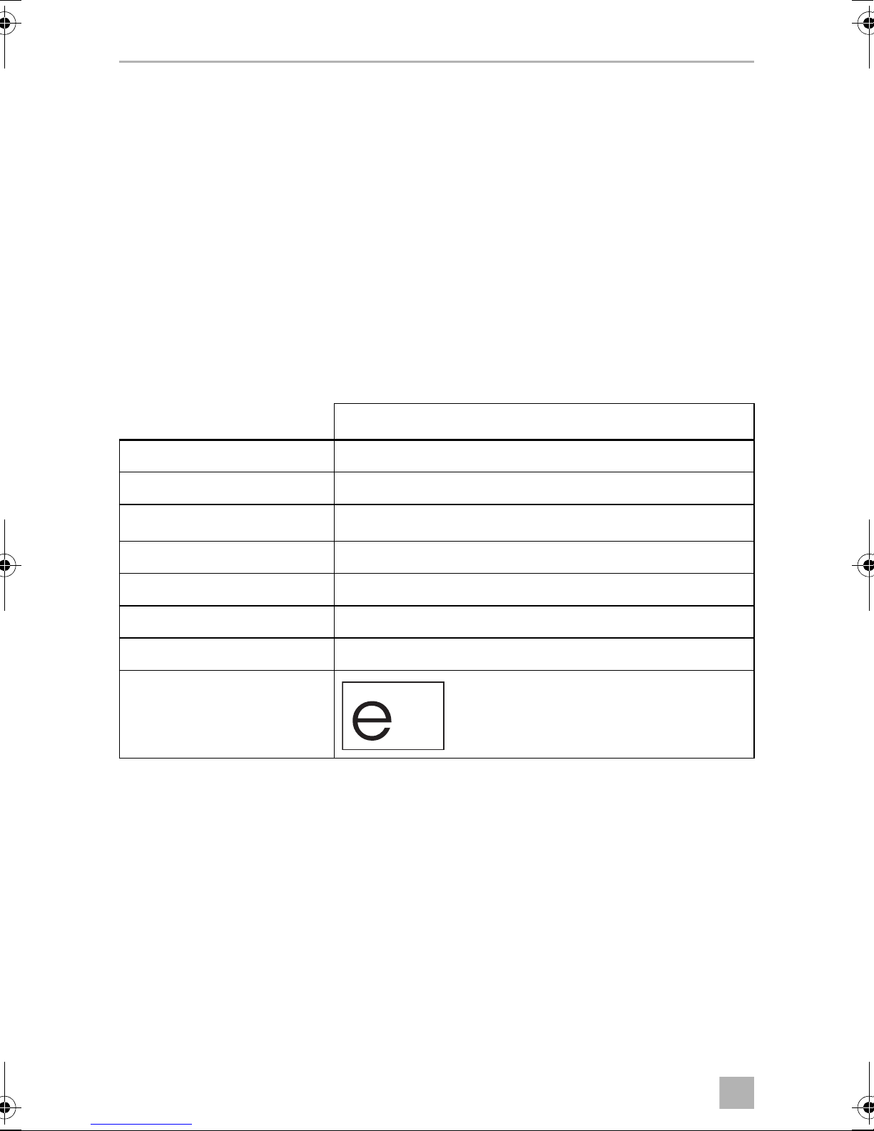
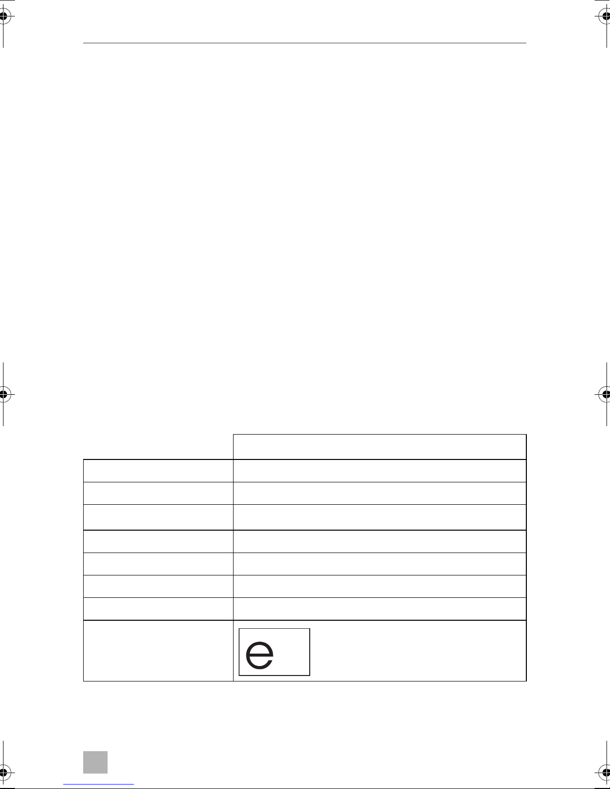
11 Technical data
CK500
Ref. no.: 9106506287
Voltage: 12 Vg
Capacity:
Power consumption: 35 W
Light intensity: 3 W
Dimensions (W x H x D): 530 x 60 x 204 mm
Weigh t: 2.5 kg
Test mark:
100 m
3
/h
18
Page 19
DE
CK500
Bitte lesen Sie diese Anleitung vor Einbau und Inbetriebnahme sorgfältig
durch und bewahren Sie sie auf. Geben Sie sie im Falle einer Weitergabe
des Produktes an den Nutzer weiter.
Inhalt
1 Erklärung der Symbole . . . . . . . . . . . . . . . . . . . . . . . . . . . . . . . . . . . . . . . . . 20
2 Sicherheitshinweise . . . . . . . . . . . . . . . . . . . . . . . . . . . . . . . . . . . . . . . . . . . 20
3 Lieferumfang . . . . . . . . . . . . . . . . . . . . . . . . . . . . . . . . . . . . . . . . . . . . . . . . . 22
4 Bestimmungsgemäßer Gebrauch . . . . . . . . . . . . . . . . . . . . . . . . . . . . . . . . 22
5 Technische Beschreibung . . . . . . . . . . . . . . . . . . . . . . . . . . . . . . . . . . . . . . 23
6 Gerät montieren . . . . . . . . . . . . . . . . . . . . . . . . . . . . . . . . . . . . . . . . . . . . . . 24
7 Gerät verwenden . . . . . . . . . . . . . . . . . . . . . . . . . . . . . . . . . . . . . . . . . . . . . 27
8 Reinigung . . . . . . . . . . . . . . . . . . . . . . . . . . . . . . . . . . . . . . . . . . . . . . . . . . . 28
9 Entsorgung . . . . . . . . . . . . . . . . . . . . . . . . . . . . . . . . . . . . . . . . . . . . . . . . . . 29
10 Gewährleistung. . . . . . . . . . . . . . . . . . . . . . . . . . . . . . . . . . . . . . . . . . . . . . . 29
11 Technische Daten . . . . . . . . . . . . . . . . . . . . . . . . . . . . . . . . . . . . . . . . . . . . . 29
19
Page 20
DE
Erklärung der Symbole CK500
1 Erklärung der Symbole
WARNUNG!
!
Sicherheitshinweis: Nichtbeachtung kann zu Tod oder schwerer
Verletzung führen.
VORSICHT!
Sicherheitshinweis: Nichtbeachtung kann zu Verletzungen führen.
!
ACHTUNG!
A
Nichtbeachtung kann zu Materialschäden führen und die Funktion des
Produktes beeinträchtigen.
HINWEIS
Ergänzende Informationen zur Bedienung des Produktes.
I
2 Sicherheitshinweise
Beachten Sie die vom Fahrzeughersteller und vom Kfz-Handwerk
vorgeschriebenen Sicherheitshinweise und Auflagen!
Der Hersteller übernimmt in folgenden Fällen keine Haftung für Schäden:
• Montage- oder Anschlussfehler
• Beschädigungen am Produkt durch mechanische Einflüsse und Über-
spannungen
• Veränderungen am Produkt ohne ausdrückliche Genehmigung vom Hersteller
• Verwendung für andere als die in der Anleitung beschriebenen Zwecke
Beachten Sie folgende grundsätzliche Sicherheitsmaßnahmen beim Gebrauch von
elektrischen Geräten zum Schutz vor:
• elektrischem Schlag
• Brandgefahr
• Verletzungen
20
Page 21

DE
CK500 Sicherheitshinweise
2.1 Umgang mit dem Gerät
WARNUNG!
!
• Die Montage und Reparaturen der Dunstabzugshaube
dürfen nur von Fachkräften durchgeführt werden, die mit den verbundenen Gefahren und den einschlägigen Vorschriften vertraut
sind.
• Durch unsachgemäße Reparaturen können erhebliche Gefahren entstehen. Wenden Sie sich im Reparaturfall an den Service-Stützpunkt in
Ihrem Land (Adressen siehe Rückseite der Anleitung).
• Dieses Gerät kann von Kindern ab 8 Jahren und darüber sowie von
Personen mit verringerten physischen, sensorischen oder mentalen
Fähigkeiten oder Mangel an Erfahrung und Wissen benutzt werden,
wenn sie beaufsichtigt oder bezüglich des sicheren Gebrauchs des
Gerätes unterwiesen wurden und die daraus resultierenden Gefahren
verstehen.
• Montagearbeiten und elektrischer Anschluss müssen von
qualifizierten Fachhandwerkern unter Einhaltung aller gültigen
Vorschriften und Normen durchgeführt werden.
• Achten Sie beim Schneiden oder Bohren in Wand oder Decke darauf,
dass keine elektrischen Leitungen oder nicht sichtbare Geräte
beschädigt werden.
!
• Der Abstand zwischen Gaskocherflamme und Dunstabzugshaube
muss mindestens 50 cm betragen.
VORSICHT!
• Die Dunstabzugshaube muss so sicher installiert werden, dass sie
nicht herabfallen kann.
• Betreiben Sie die Dunstabzugshaube nur, wenn das Gehäuse und die
Leitungen unbeschädigt sind.
• Führen Sie keine Fremdgegenstande in das Gerät ein.
21
Page 22
DE
Lieferumfang CK500
3 Lieferumfang
Pos. in
Abb. 1,
Seite 3
1 1 Dunstabzugshaube CK500
2 1 Abluftschlauch
3 1 Oberteil des Pilzlüfters
4 1 Unterteil des Pilzlüfters
5 1 Abluftadapter
63Klebesockel
– 5 Kabelbinder
Menge Beschreibung
4 Bestimmungsgemäßer Gebrauch
Die Dunstabzugshaube CK500 (Art.-Nr. 9106506287) ist für den Einbau in Freizeitfahrzeuge wie Wohnwagen, Wohnmobile und Boote vorgesehen.
22
Page 23
DE
CK500 Technische Beschreibung
5 Technische Beschreibung
Die Dunstabzugshaube CK500 entfernt beim Kochen entstehende Gerüche und
Dampf. Ihr Filter ist abnehmbar und waschbar.
CK500 verfügt über eine LED-Leuchte, zwei Lüfter und ein Touch-Display.
Die Abluft kann nach oben oder nach hinten abgeführt werden.
5.1 Bedienelemente
Pos. in
Abb. 2,
Seite 3
1 Schaltet das Licht ein und aus
2 Erhöht die Lüftergeschwindigkeit und stellt die Uhrzeit ein
Beschreibung
3 Zeigt die Lüftergeschwindigkeit an
4 Zeigt die Uhrzeit an
5 Leuchtet, wenn das Licht eingeschaltet ist
6 Verringert die Lüftergeschwindigkeit und stellt die Uhrzeit ein
7 Schaltet die Dunstabzugshaube ein und aus
5.2 Filter
Pos. in
Abb. 3,
Seite 3
1 Filter
2 Verriegelung
Beschreibung
nach hinten schieben: entriegeln und Filter abnehmen
23
Page 24
DE
Gerät montieren CK500
6Gerät montieren
WARNUNG!
!
A
I
Der Abstand zwischen Gaskocherflamme und Dunstabzugshaube muss
mindestens 50 cm betragen.
ACHTUNG!
Achten Sie beim Planen der Abluftführung darauf, dass in diesem
Bereich keine elektrischen Leitungen oder Fahrzeugteile wie z. B. eine
Dachreling sind. Sie könnten sonst beim Bohren beschädigt werden.
HINWEIS
• In diesem Kapitel wird beschrieben, wie die Abluft nach oben
abgeführt wird.
• Die Abluft kann auch zur Seite abgeführt werden. Weiteres Zubehör
ist dafür nötig. Lassen Sie die Dunstabzugshaube in diesem Fall nur
durch eine Fachwerkstatt einbauen.
6.1 Hinweise zum Montageort
• Die Dunstabzugshaube soll vorzugsweise mittig über der Kochstelle
angebracht und nach Möglichkeit unter einen Hängeschrank montiert werden.
• Der Abstand zwischen Gaskocherflamme und Dunstabzugshaube muss mindestens 50 cm betragen.
• Die Abluft kann nach oben oder zur Seite abgeführt werden.
Wenn die Abluft zur Seite abgeführt werden soll, muss ein zusätzlicher Lüfter
(nicht im Lieferumfang enthalten) eingesetzt werden.
• Vor dem Einbau muss geklärt sein, wie der Abluftschlauch verlegt und wo der
Pilzlüfter montiert werden kann (Abb. 4, Seite 4).
Beachten Sie dabei auch Schranktrennwände und Zwischenböden.
Die Löcher für den Abluftschlauch müssen so platziert werden, dass keine
elektrischen Leitungen im Aufbau, keine tragenden Strukturen des Aufbaus oder
Fahrzeugteile wie z. B. eine Dachreling betroffen sind.
24
Page 25

DE
CK500 Gerät montieren
6.2 Abluftführung vorbereiten
Abluftadapter montieren
➤ Entfernen Sie die Abdeckung des Abluftanschlusses (Abb. 5 A, Seite 4).
➤ Montieren Sie den Abluftadapter (Abb. 5 B, Seite 4).
Hängeschrank vorbereiten
➤ Zeichnen Sie den Mittelpunkt des Durchgangsloch für den Abluftschlauch am
Hängeschrank an (Abb. 6, Seite 5).
➤ Bohren Sie im Boden des Hängeschranks ein Durchgangsloch mit einem
Durchmesser von 75 – 80 mm.
Dachdurchführung vorbeiten
Für den Abluftschlauch muss an geeigneter Stelle im Dach ein Durchgangsloch mit
einem Durchmesser von 110 mm gefertigt werden (Abb. 4, Seite 4).
Gehen Sie dazu wie folgt vor, damit das Dach nicht ausreißt:
➤ Bohren Sie zunächst von innen mit einem kleineren Bohrer
(Durchmesser 3 – 5 mm) ein Loch durch das Dach.
➤ Bohren Sie von oben das Loch mit Durchmesser 110 mm bis zu 2/3 der
Dachdicke.
➤ Bohren Sie von unten vollends durch das Dach.
25
Page 26

DE
Gerät montieren CK500
6.3 Dunstabzugshaube montieren und anschließen
➤ Schieben Sie den Abluftschlauch (Abb. 7 1, Seite 5) auf den Abluftadapter an
der Dunstabzugshaube (Abb. 7 2, Seite 5).
➤ Fixieren Sie den Abluftschlauch am Abluftadapter mit einem Kabelbinder.
➤ Entfernen Sie den Filter.
➤ Heben Sie die Dunstabzugshaube in die gewünschte Position und führen Sie
dabei den Abluftschlauch und das Anschlusskabel durch das Durchgangsloch im
Hängeschrank.
➤ Befestigen Sie die Dunstabzugshaube mit vier Schrauben (Abb. 8, Seite 6).
Verwenden Sie dazu Schrauben mit folgenden Maßen:
– Durchmesser 4 mm
– Länge entsprechend der Dicke des Schrankbodens
➤ Setzen Sie den Filter wieder ein.
➤ Schließen Sie das Anschlusskabel an die Gleichstromversorgung an.
Achten Sie dabei auf die richtige Polung.
6.4 Abluftführung fertigstellen
➤ Entfetten und reinigen Sie die Umgebung des Dachausschnittes.
➤ Versehen Sie das Oberteil des Pilzlüfters mit einer dauerelastischen Dichtmasse
(z. B. Dekalin) (Abb. 9, Seite 6).
➤ Setzen Sie das Oberteil des Pilzlüfters in den Dachausschnitt ein.
➤ Schieben Sie den Abluftschlauch auf das Unterteil des Pilzlüfters (Abb. 0,
Seite 7).
➤ Fixieren Sie den Abluftschlauch am Unterteil des Pilzlüfters mit einem Kabel-
binder.
➤ Schieben Sie das Unterteil des Pilzlüfters von innen in das Oberteil (Abb. a,
Seite 7).
➤ Befestigen Sie das Unterteil des Pilzlüfters mit drei Schrauben.
Verwenden Sie dazu Schrauben mit folgenden Maßen:
– Durchmesser 4 mm
– Länge = Dachdicke – 10 mm
➤ Fixieren Sie den Abluftschlauch mit den Klebesockeln (Abb. 4 1, Seite 4) und
Kabelbindern an geeigneten Stellen.
26
Page 27
DE
CK500 Gerät verwenden
7Gerät verwenden
7.1 Dunstabzugshaube ein- und ausschalten
➤ Berühren Sie die Schaltfläche , um die Dunstabzugshaube ein- oder auszu-
schalten.
7.2 Uhr einstellen
HINWEIS
I
➤ Schalten Sie die Dunstabzugshaube ein.
• Wenn die Dunstabzugshaube an die Stromzufuhr angeschlossen
wird, ist auf der Anzeige 00:00 zu sehen.
• Nach drei Sekunden ohne Eingabe werden die Einstellungen
gespeichert.
➤ Berühren Sie die Schaltfläche für drei Sekunden, um die Stunden einzustellen.
✓ Ein Bestätigungston ertönt.
✓ Alle Ziffern der Uhrzeit blinken.
➤ Stellen Sie mit den Schaltflächen oder die Stunden ein.
➤ Berühren Sie die Schaltfläche für 3 Sekunden, um die Minuten einzustellen.
✓ Ein Bestätigungston ertönt.
✓ Alle Ziffern der Uhrzeit blinken.
➤ Stellen Sie mit den Schaltflächen oder die Minuten ein.
➤ Warten Sie drei Sekunden.
✓ Die Ziffern der Uhrzeit leuchten konstant.
✓ Die neu eingestellte Uhrzeit ist gespeichert.
HINWEIS
I
In der Zeit zwischen 20.00 Uhr und 06.00 Uhr erlischt die Anzeige der
Uhrzeit nach 5 Minuten, wenn keine Schaltfläche berührt wird.
7.3 Licht ein- und ausschalten
➤ Berühren Sie die Schaltfläche , um das Licht ein- und auszuschalten.
27
Page 28
DE
Reinigung CK500
7.4 Lüftergeschwindigkeit einstellen
➤ Berühren Sie die Schaltfläche , um die Lüftergeschwindigkeit zu erhöhen.
➤ Berühren Sie die Schaltfläche , um die Lüftergeschwindigkeit zu
verringern.
8 Reinigung
ACHTUNG!
A
• Keine scharfen oder harten Gegenstände oder Reinigungsmittel zur
Reinigung verwenden, da dies zu einer Beschädigung des
Produktes führen kann.
• Die elektronischen Komponenten der Dunstabzugshaube nicht mit
Wasser oder einem nassen Tuch reinigen.
HINWEIS
I
➤ Schalten Sie die Dunstabzugshaube aus.
➤ Reinigen Sie das Produkt gelegentlich mit einem feuchten Tuch und
synthetischem Reinigungsmittel (z. B. Spülmittel).
➤ Entnehmen Sie den Filter und reinigen Sie den Filter mit warmem Wasser und
synthetischem Reinigungsmittel (z. B. Spülmittel).
➤ Lassen Sie den Filter trocknen, bevor Sie ihn wieder einsetzen.
• Der Filter der Dunstabzugshaube muss regelmäßig gereinigt
werden, da sich dort Fett sammelt. Wie oft eine Reinigung nötig ist,
hängt davon ab, wie oft gekocht und wie oft die Dunstabzugshaube
eingeschaltet wird.
• Reinigen Sie den Filter, bevor die Leistung der Dunstabzugshaube
merklich nachlässt.
• Der Filter kann ersetzt werden. Wenden Sie sich bitte an die
Niederlassung des Herstellers in Ihrem Land (Adressen siehe
Rückseite der Anleitung) oder an Ihren Fachhändler.
28
Page 29
DE
CK500 Entsorgung
5
9Entsorgung
➤ Geben Sie das Verpackungsmaterial möglichst in den entsprechenden
Recycling-Müll.
Wenn Sie das Produkt endgültig außer Betrieb nehmen, informieren Sie
sich bitte beim nächsten Recyclingcenter oder bei Ihrem Fachhändler
M
über die zutreffenden Entsorgungsvorschriften.
10 Gewährleistung
Es gilt die gesetzliche Gewährleistungsfrist. Sollte das Produkt defekt sein, wenden
Sie sich bitte an die Niederlassung des Herstellers in Ihrem Land (Adressen siehe
Rückseite der Anleitung) oder an Ihren Fachhändler.
Zur Reparatur- bzw. Gewährleistungsbearbeitung müssen Sie folgende Unterlagen
mitschicken:
• eine Kopie der Rechnung mit Kaufdatum,
• einen Reklamationsgrund oder eine Fehlerbeschreibung.
11 Technische Daten
CK500
Artikelnummer: 9106506287
Anschlussspannung: 12 Vg
Kapazität:
Leistungsaufnahme: 35 W
Beleuchtungsstärke: 3 W
Abmessungen (B x H x T): 530 x 60 x 204 mm
Gewicht: 2,5 kg
100 m
3
/h
Prüfzeichen:
29
Page 30
FR
CK500
Veuillez lire attentivement cette notice avant le montage et la mise en
service. Veuillez ensuite la conserver. En cas de passer le produit, veuillez
le transmettre au nouvel acquéreur.
Contenu
1 Explication des symboles . . . . . . . . . . . . . . . . . . . . . . . . . . . . . . . . . . . . . . . .31
2 Consignes de sécurité . . . . . . . . . . . . . . . . . . . . . . . . . . . . . . . . . . . . . . . . . .31
3 Pièces fournies . . . . . . . . . . . . . . . . . . . . . . . . . . . . . . . . . . . . . . . . . . . . . . . 33
4 Usage conforme . . . . . . . . . . . . . . . . . . . . . . . . . . . . . . . . . . . . . . . . . . . . . . 33
5 Description technique . . . . . . . . . . . . . . . . . . . . . . . . . . . . . . . . . . . . . . . . . 33
6 Montage de l'appareil . . . . . . . . . . . . . . . . . . . . . . . . . . . . . . . . . . . . . . . . . 35
7 Utilisation de l'appareil. . . . . . . . . . . . . . . . . . . . . . . . . . . . . . . . . . . . . . . . . 38
8 Nettoyage . . . . . . . . . . . . . . . . . . . . . . . . . . . . . . . . . . . . . . . . . . . . . . . . . . . 39
9 Retraitement . . . . . . . . . . . . . . . . . . . . . . . . . . . . . . . . . . . . . . . . . . . . . . . . . 40
10 Garantie. . . . . . . . . . . . . . . . . . . . . . . . . . . . . . . . . . . . . . . . . . . . . . . . . . . . . 40
11 Caractéristiques techniques . . . . . . . . . . . . . . . . . . . . . . . . . . . . . . . . . . . . . 40
30
Page 31

FR
CK500 Explication des symboles
1 Explication des symboles
AVERTISSEMENT !
!
!
A
Consigne de sécurité : le non-respect de ces consignes peut entraîner
la mort ou de graves blessures.
ATTENTION !
Consigne de sécurité : le non-respect de ces consignes peut entraîner
des blessures.
AVIS !
Le non-respect de ces consignes peut entraîner des dommages
matériels et des dysfonctionnements du produit.
REMARQUE
Informations complémentaires sur l'utilisation du produit.
I
2 Consignes de sécurité
Respectez les consignes de sécurité et autres prescriptions imposées par
le fabricant du véhicule et par les professionnels de l’automobile !
Le fabricant décline toute responsabilité pour des dommages dans les cas suivants :
• des défauts de montage ou de raccordement
• des influences mécaniques et des surtensions ayant endommagé le matériel
• des modifications apportées au produit sans autorisation explicite de la part du
fabricant
• une utilisation différente de celle décrite dans la notice
Lors de l'utilisation d'appareils électriques, les consignes générales de sécurité
suivantes doivent être respectées afin d'éviter :
• une décharge électrique
• un incendie
• des blessures
31
Page 32

FR
Consignes de sécurité CK500
2.1 Précautions d'usage
AVERTISSEMENT !
!
• Le montage et les réparations de la hotte aspirante doivent être
effectués par un personnel qualifié et parfaitement informé des
dangers et règlements spécifiques à ces manipulations.
• Toute réparation mal effectuée risquerait d'entraîner de graves
dangers. Si des réparations sont nécessaires, adressez-vous à la filiale
chargée du service après-vente dans votre pays (adresses au dos du
manuel).
• Les enfants âgés de 8 ans et plus ainsi que les personnes ayant des
déficiences physiques, sensorielles ou mentales ou un manque
d'expérience ou de connaissances peuvent utiliser ce produit à
condition d'être sous surveillance ou d'avoir reçu des instructions
concernant l'utilisation de l'appareil en toute sécurité et de
comprendre les dangers qui en résultent.
• Les travaux de montage et le raccordement électrique doivent être
effectués par des artisans qualifiés, dans le respect de toutes les
directives et normes en vigueur.
• Lors de la découpe ou du perçage dans les murs ou les plafonds,
veillez à ce qu'aucune conduite électrique ou appareil non visible ne
soit endommagé.
!
• La distance entre la flamme d'un réchaud à gaz et la hotte doit être
d'au moins 50 cm.
ATTENTION !
• La hotte doit être installée de manière à ce qu'elle ne puisse pas
tomber.
• Ne faites fonctionner la hotte que si le bâti et les raccordements sont
intacts.
• N'introduisez aucun corps étranger dans l'appareil.
32
Page 33

FR
CK500 Pièces fournies
3Pièces fournies
Pos.
dans
fig. 1,
page 3
1 1 Hotte aspirante CK500
2 1 Flexible d'échappement
3 1 Partie supérieure du ventilateur
4 1 Partie inférieure du ventilateur
5 1 Adaptateur d'évacuation d'air
6 3 Socle collant
– 5 Serre-câbles
Quantité Description
4Usage conforme
La hotte aspirante CK500 (n° d'article 9106506287) est conçue pour le montage
dans des véhicules de loisirs comme des caravanes, campings-cars et bateaux.
5 Description technique
La hotte aspirante CK500 élimine les mauvaises odeurs et la vapeur se formant lors
de la cuisson. Votre filtre est amovible et lavable.
CK500 dispose d'une lampe LED, de deux ventilateurs et d'un écran tactile.
L'échappement peut être orienté vers le haut ou vers l'arrière.
33
Page 34

FR
Description technique CK500
5.1 Éléments de commande
Pos.
dans
fig. 2,
page 3
1 Allume et éteint la lumière
2 Augmente la vitesse du ventilateur et permet de régler l'heure
3 Affiche la vitesse du ventilateur
4 Affiche l'heure
5 S'allume quand la lumière est allumée
6 Diminue la vitesse du ventilateur et permet de régler l'heure
7 Permet d'allumer ou d'éteindre la hotte aspirante
Description
5.2 Filtre
Pos.
dans
fig. 3,
page 3
1 Filtre
2 Verrouillage
Description
Pousser vers l'arrière : déverrouiller et retirer le filtre
34
Page 35

FR
CK500 Montage de l'appareil
6Montage de l'appareil
AVERTISSEMENT !
!
A
I
La distance entre la flamme d'un réchaud à gaz et la hotte doit être d'au
moins 50 cm.
AVIS !
Lors de la planification du conduit d'échappement, veillez à ce qu'il n'y
ait pas dans cette zone de câbles électriques ou de pièces du véhicule
tels que des rails de toit par exemple. Ils pourraient sinon être endommagées lors du perçage.
REMARQUE
• Ce chapitre décrit comment le conduit d'échappement est orienté
vers le haut.
• L'échappement peut également être orienté sur le côté. D'autres
accessoires sont nécessaires pour cela. Dans ce cas, faites installer la
hotte aspirante uniquement par un garage spécialisé.
6.1 Consignes relatives au lieu de montage
• La hotte aspirante doit être installée de préférence au-dessus des plaques de
cuisson, au milieu, et montée si possible sous une armoire suspendue.
• La distance entre la flamme d'un réchaud à gaz et la hotte doit être d'au moins
50 cm.
• L'échappement peut être orienté vers le haut ou sur le côté.
Si l'échappement doit être orienté vers le côté, un ventilateur supplémentaire
(non compris dans la livraison) doit être utilisé.
• Avant l'installation, il faut savoir comment le tuyau d'échappement doit être posé
et où le ventilateur peut être monté (fig. 4, page 4).
Tenez également compte à cet égard des parois de séparation des armoires et
des étagères.
Les trous pour le tuyau d'échappement doivent être placés de manière à ce
qu'aucun câble électrique, aucune structure portante de la construction ni
aucune pièce du véhicule comme par exemple des rails de toit ne soit concerné.
35
Page 36

FR
Montage de l'appareil CK500
6.2 Préparation du conduit d'échappement
Montage de l'adaptateur d'échappement
➤ Enlevez le cache du raccordement d'échappement (fig. 5 A, page 4).
➤ Montez l'adaptateur d'échappement (fig. 5 B, page 4).
Préparation de l'armoire murale
➤ Marquez au crayon le centre du trou de passage pour le tuyau d'échappement
dans l'armoire (fig. 6, page 5).
➤ Percez dans le fond de l'armoire murale un trou de passage d'un diamètre de
75 – 80 mm.
Préparation du passage du toit
Un trou de passage d'un diamètre de 110 mm doit être découpé dans le toit, à
l'endroit approprié, pour le tuyau d'échappement (fig. 4, page 4).
Procédez comme suit pour ce faire, afin que le toit ne se déchire pas :
➤ percez tout d'abord de l'intérieur, avec un petit foret
(diamètre 3 – 5 mm), un trou dans le toit.
➤ Percez d'en haut le trou avec un diamètre de 110 mm jusqu'à 2/3 de l'épaisseur
du toit.
➤ Finissez par percer d'en bas à travers le toit.
36
Page 37

FR
CK500 Montage de l'appareil
6.3 Montage et raccordement de la hotte
➤ Faites glisser le tuyau d'échappement (fig. 7 1, page 5) sur l'adaptateur au
niveau de la hotte aspirante (fig. 7 2, page 5).
➤ Fixez le tuyau d'échappement sur l'adaptateur d'échappement avec un
serre-câbles.
➤ Retirez le filtre.
➤ Soulevez la hotte aspirante dans la position désirée et faites passer en même
temps le tuyau d'échappement et le câble de connexion à travers le trou de
passage dans l'armoire murale.
➤ Fixez la hotte aspirante avec quatre vis (fig. 8, page 6).
Utilisez à cet effet des vis des dimensions suivantes :
– diamètre de 4 mm
– Longueur en fonction de l'épaisseur du fond de l'armoire
➤ Remettez le filtre en place.
➤ Branchez le câble de raccordement à la tension continue.
Ce faisant, respectez la polarité.
6.4 Finition du conduit d'échappement
➤ Dégraissez et nettoyez l'entourage de la découpe du toit.
➤ Appliquez sur la partie supérieure du ventilateur un mastic souple
(p. ex. Dekalin) (fig. 9, page 6).
➤ Installez la partie supérieure du ventilateur dans la découpe du toit.
➤ Faites glisser le tuyau d'échappement sur la partie inférieure du
ventilateur (fig. 0, page 7).
➤ Fixez le tuyau d'échappement sur la partie inférieure du ventilateur avec un
serre-câbles.
➤ Insérez la partie inférieure du ventilateur, de l'intérieur, dans la partie supérieure
(fig. a, page 7).
➤ Fixez la partie inférieure du ventilateur avec trois vis.
Utilisez à cet effet des vis des dimensions suivantes :
– diamètre de 4 mm
– Longueur = épaisseur du toit – 10 mm
➤ Fixez le flexible d'échappement avec les socles collants (fig. 4 1, page 4) et les
serre-câbles aux endroits appropriés.
37
Page 38

FR
Utilisation de l'appareil CK500
7 Utilisation de l'appareil
7.1 Mise en marche / à l'arrêt de la hotte aspirante
➤ Appuyez sur la touche pour allumer ou éteindre la hotte aspirante.
7.2 Réglage de l'heure
REMARQUE
I
➤ Mettez la hotte aspirante en marche.
➤ Appuyez sur le bouton pendant trois secondes pour régler les heures.
• Lorsque la hotte aspirante est raccordée à l'alimentation électrique,
00:00 apparaît sur l'affichage.
• Au bout de trois secondes sans saisie, les réglages sont mémorisés.
✓ Un signal sonore de confirmation retentit.
✓ Tous les chiffres de l'heure clignotent.
➤ Réglez les heures à l'aide des touches ou .
➤ Appuyez sur le bouton pendant 3 secondes pour régler les minutes.
✓ Un signal sonore de confirmation retentit.
✓ Tous les chiffres de l'heure clignotent.
➤ Réglez les minutes à l'aide des touches ou .
➤ Attendez trois secondes.
✓ Les chiffres de l'heure restent allumés en permanence.
✓ Le nouveau réglage de l'heure est enregistré.
REMARQUE
I
Dans l'intervalle de temps entre 20h00 et 06h00, l'affichage de l'heure
s'éteint après 5 minutes, si aucune touche n'est actionnée.
7.3 Mise en marche / à l'arrêt de la lumière
➤ Appuyez sur la touche pour allumer ou éteindre la lumière.
38
Page 39

FR
CK500 Nettoyage
7.4 Réglage de la vitesse du ventilateur
➤ Appuyez sur la touche pour augmenter la vitesse du ventilateur.
➤ Appuyez sur la touche pour diminuer la vitesse du ventilateur.
8Nettoyage
AVIS !
A
I
• N'utilisez aucun objet coupant ou dur, ni de détergents pour le
nettoyage. Cela pourrait endommager le produit.
• Ne pas nettoyer les composants électroniques de la hotte aspirante
avec de l'eau ou un chiffon humide.
REMARQUE
• Le filtre de la hotte aspirante doit être nettoyé régulièrement, car de
la graisse s'y accumule. La fréquence de nettoyage dépend de la
fréquence des cuissons et de la fréquence d'allumage de la hotte
aspirante.
• N'attendez pas que la puissance de la hotte aspirante soit
sensiblement réduite pour nettoyer le filtre.
• Le filtre peut être remplacé. Adressez-vous à la succursale du fabricant de votre pays (adresses au dos du manuel) ou à votre revendeur.
➤ Mettez la hotte aspirante à l'arrêt.
➤ Nettoyez de temps en temps le produit avec un chiffon humide et un détergent
synthétique (p. ex. produit vaisselle).
➤ Retirez le filtre et nettoyez le filtre à l'eau chaude et au détergent synthétique
(p. ex. produit lave-vaisselle).
➤ Laissez sécher le filtre avant de l'utiliser de nouveau.
39
Page 40

FR
Retraitement CK500
5
9 Retraitement
➤ Jetez les emballages dans les conteneurs de déchets recyclables prévus à cet
effet.
Lorsque vous mettrez votre produit définitivement hors service, informezvous auprès du centre de recyclage le plus proche ou auprès de votre
M
revendeur spécialisé sur les prescriptions relatives au retraitement des
déchets.
10 Garantie
Le délai légal de garantie s'applique. Si le produit s'avérait défectueux, veuillez vous
adresser à la filiale du fabricant située dans votre pays (voir adresses au verso du
présent manuel) ou à votre revendeur spécialisé.
Veuillez y joindre les documents suivants pour la gestion des réparations et de la
garantie :
• une copie de la facture avec la date d'achat,
• le motif de la réclamation ou une description du dysfonctionnement.
11 Caractéristiques techniques
CK500
Référence : 9106506287
Tension de raccordement : 12 Vg
Capacité :
Puissance absorbée : 35 W
Intensité lumineuse : 3 W
Dimensions (l x h x p) : 530 x 60 x 204 mm
Poids : 2,5 kg
100 m
3
/h
Conformité :
40
Page 41

ES
CK500
Lea detenidamente estas instrucciones antes de llevar a cabo la instalación
y puesta en funcionamiento, y consérvelas en un lugar seguro. En caso de
vender o entregar el producto a otra persona, entregue también estas
instrucciones.
Índice
1 Explicación de los símbolos . . . . . . . . . . . . . . . . . . . . . . . . . . . . . . . . . . . . . 42
2 Indicaciones de seguridad . . . . . . . . . . . . . . . . . . . . . . . . . . . . . . . . . . . . . . 42
3 Volumen de entrega . . . . . . . . . . . . . . . . . . . . . . . . . . . . . . . . . . . . . . . . . . . 44
4 Uso adecuado . . . . . . . . . . . . . . . . . . . . . . . . . . . . . . . . . . . . . . . . . . . . . . . . 44
5 Descripción técnica . . . . . . . . . . . . . . . . . . . . . . . . . . . . . . . . . . . . . . . . . . . 44
6 Montaje del aparato . . . . . . . . . . . . . . . . . . . . . . . . . . . . . . . . . . . . . . . . . . . 46
7 Utilización del dispositivo. . . . . . . . . . . . . . . . . . . . . . . . . . . . . . . . . . . . . . . 49
8 Limpieza. . . . . . . . . . . . . . . . . . . . . . . . . . . . . . . . . . . . . . . . . . . . . . . . . . . . . 50
9 Gestión de residuos . . . . . . . . . . . . . . . . . . . . . . . . . . . . . . . . . . . . . . . . . . . .51
10 Garantía legal . . . . . . . . . . . . . . . . . . . . . . . . . . . . . . . . . . . . . . . . . . . . . . . . .51
11 Datos técnicos. . . . . . . . . . . . . . . . . . . . . . . . . . . . . . . . . . . . . . . . . . . . . . . . .51
41
Page 42

ES
Explicación de los símbolos CK500
1 Explicación de los símbolos
¡ADVERTENCIA!
!
!
A
Indicación de seguridad: su incumplimiento puede acarrear la
muerte o graves lesiones.
¡ATENCIÓN!
Indicación de seguridad: su incumplimiento puede acarrear
lesiones.
¡AVISO!
Su incumplimiento puede acarrear daños materiales y perjudicar el
correcto funcionamiento del producto.
NOTA
Información adicional para el manejo del producto.
I
2 Indicaciones de seguridad
Tenga en cuenta las indicaciones de seguridad y la documentación
suministrada por el fabricante y el taller del vehículo.
El fabricante declina toda responsabilidad ante daños ocurridos en los siguientes
casos:
• errores de montaje o de conexión
• daños en el producto debido a influencias mecánicas y sobretensiones
• modificaciones realizadas en el producto sin el expreso consentimiento del
fabricante
• utilización del aparato para fines distintos a los descritos en las instrucciones
Al utilizar aparatos eléctricos, respete las siguientes normas básicas de seguridad
para protegerse de:
• descargas eléctricas
• peligro de incendio
• lesiones
42
Page 43

ES
CK500 Indicaciones de seguridad
2.1 Manejo del aparato
¡ADVERTENCIA!
!
• Solo personal técnico que conozca los posibles peligros y las normas
correspondientes tiene autorización para instalar y reparar la campana
extractora.
• Una reparación incorrecta entraña riesgos considerables. En caso de
reparaciones, diríjase al punto de atención al cliente de su país
(véanse las direcciones en el dorso de las instrucciones).
• Los niños mayores de 8 años y las personas de capacidad física,
sensorial o mental disminuida, así como aquellas personas con falta de
experiencia y conocimientos suficientes, solo podrán utilizar este
aparato bajo vigilancia o si han sido instruidos respecto al uso seguro
del aparato y a los posibles peligros que pueden emanar de él.
• Los trabajos de montaje y conexión eléctrica deben ser realizados por
personas cualificadas para tal efecto, respetando todos los
reglamentos y normas vigentes.
• Cuando taladre o perfore la pared o el techo, preste atención a no
dañar ningún cable eléctrico o aparatos no visibles.
• La distancia entre la llama del hornillo de gas y la campana extractora
debe ser como mínimo de 50 cm.
!
¡ATENCIÓN!
• Instale la campana extractora de forma segura para evitar que se
pueda caer.
• Use la campana extractora solo cuando la carcasa y los cables no
presenten daños.
• No introduzca en el dispositivo objetos extraños.
43
Page 44

ES
Volumen de entrega CK500
3 Volumen de entrega
Pos. en
fig. 1,
página 3
1 1 Campana extractora CK500
2 1 Manguera de aire de escape
3 1 Parte superior del ventilador de seta
4 1 Parte inferior del ventilador de seta
5 1 Adaptador de ventilación
6 3 Soporte adhesivo
– 5 Abrazadera para cables
Cantidad Descripción
4Uso adecuado
La campana extractora CK500 (n.° de art. 9106506287) está previsto para ser
integrado en autocaravanas, caravanas y embarcaciones.
5 Descripción técnica
La campana extractora CK500 elimina los olores y el vapor originados al cocinar. Su
filtro se puede extraer y lavar.
La CK500 dispone de una luz LED, dos ventiladores y una pantalla táctil.
El aire de salida puede ser dirigido hacia arriba o hacia atrás.
44
Page 45

ES
CK500 Descripción técnica
5.1 Elementos de mando
Pos. en
fig. 2,
página 3
1 Enciende o apaga la luz
2 Aumenta la velocidad del ventilador y ajusta la hora
3 Muestra la velocidad del ventilador
4Muestra la hora
5 Brilla cuando se ha encendido la luz
6 Disminuye la velocidad del ventilador y ajusta la hora
7 Enciende y apaga la campana extractora
Descripción
5.2 Filtro
Pos. en
fig. 3,
página 3
1 Filtro
2Bloqueo
Descripción
deberá moverse hacia atrás para desbloquear y extraer el filtro
45
Page 46

ES
Montaje del aparato CK500
6 Montaje del aparato
¡ADVERTENCIA!
!
A
I
La distancia entre la llama del hornillo de gas y la campana extractora
debe ser como mínimo de 50 cm.
¡AVISO!
Al planificar cómo se dirigirá el aire de salida, observe que en este área
no haya cables eléctricos o piezas del vehículo como p. ej. un soporte
portaequipajes. Estos podrían dañarse al taladrar.
NOTA
• En este capítulo se describe cómo se dirige hacia arriba el aire de
salida.
• El aire de salida puede también dirigirse hacia un lado. Para ello
harán falta accesorios adicionales. En este caso, confíe exclusivamente en un taller especializado para la instalación de la campana
extractora.
6.1 Indicaciones relativas al lugar de montaje
• La campana extractora debe colocarse preferiblemente en posición central por
encima del hornillo y, si es posible, montarse en un armario suspendido.
• La distancia entre la llama del hornillo de gas y la campana extractora debe ser
como mínimo de 50 cm.
• El aire de salida puede ser dirigido hacia arriba o hacia un lado.
En caso de que el aire de salida deba dirigirse hacia un lado, deberá emplearse
un ventilador adicional (no incluido en el volumen de entrega).
• Antes del montaje deberá aclararse cómo se montará la manguera de aire de
salida y dónde se puede montar el ventilador de seta (fig. 4, página 4).
Para ello deberán observarse también las paredes separadoras y los estantes del
armario.
Los orificios para la manguera de aire de salida deberán ubicarse de tal modo
que no se vean afectados los cables eléctricos durante el montaje, las estructuras
portantes de la instalación o partes del vehículo como un soporte
portaequipajes.
46
Page 47

ES
CK500 Montaje del aparato
6.2 Preparación de la salida de aire
Montaje del adaptador de aire de salida
➤ Retire la tapa de la conexión de aire de salida (fig. 5 A, página 4).
➤ Monte el adaptador de aire de salida (fig. 5 B, página 4).
Preparación del armario suspendido
➤ Señale el punto central del orificio de paso para la manguera de aire de salida en
el armario suspendido (fig. 6, página 5).
➤ Taladre en la base del armario suspendido un orificio de paso con un diámetro
de 75 – 80 mm.
Preparación del acceso por el techo
Para la manguera de aire de salida debe prepararse en el techo un orificio de paso
con un diámetro de 110 mm (fig. 4, página 4).
Proceda del siguiente modo para que el techo no se quiebre:
➤ A continuación, desde dentro y con un taladro de broca pequeña
(3 – 5 mm de diámetro), realice un agujero en el techo.
➤ Taladre desde arriba el orificio de 110 mm de diámetro hasta 2/3 del grosor del
techo.
➤ Finalice desde abajo el orificio a través del techo.
47
Page 48

ES
Montaje del aparato CK500
6.3 Montaje y conexión de la campana extractora
➤ Coloque la manguera del aire de salida (fig. 7 1, página 5) en el adaptador de
aire de salida en la campana extractora (fig. 7 2, página 5).
➤ Fije la manguera de aire de salida en el adaptador de aire de salida con una
abrazadera para cables.
➤ Retire el filtro.
➤ Eleve la campana extractora hasta la posición deseada e introduzca la manguera
de aire de salida y el cable de conexión por el orificio de paso en el armario
suspendido.
➤ Fije la campana extractora con cuatro tornillos (fig. 8, página 6).
Emplee para ello tornillos con las siguientes dimensiones:
– 4 mm de diámetro
– Longitud correspondiente al grosor de la base del armario
➤ Vuelva a colocar el filtro.
➤ Conecte el cable de conexión a la alimentación de corriente continua.
Preste atención a la polaridad correcta.
6.4 Finalización de la salida de aire
➤ Desengrase y limpie el entorno de la abertura en el techo.
➤ Aplique en la parte superior del ventilador de seta un sellador flexible
(p. ej. Dekalin) (fig. 9, página 6).
➤ Coloque la parte superior del ventilador de seta en la abertura del techo.
➤ Introduzca la manguera de aire de salida por la parte interior del ventilador de
seta (fig. 0, página 7).
➤ Fije la manguera de aire de salida en la parte inferior del ventilador de seta con
una abrazadera para cables.
➤ Introduzca la parte interior del ventilador de seta desde dentro en la parte
superior (fig. a, página 7).
➤ Fije la parte inferior del ventilador de seta con tres tornillos.
Emplee para ello tornillos con las siguientes dimensiones:
– 4 mm de diámetro
– Longitud = grosor del techo – 10 mm
➤ Fije la manguera de aire de salida con soportes adhesivos (fig. 4 1, página 4) y
abrazaderas de cables en los puntos adecuados.
48
Page 49

ES
CK500 Utilización del dispositivo
7 Utilización del dispositivo
7.1 Encender y apagar la campana extractora
➤ Pulse el botón para encender o apagar la campana extractora.
7.2 Ajuste del reloj
NOTA
I
➤ Encienda la campana extractora.
• Cuando se conecte la campana extractora a la alimentación de
corriente, se verá en la pantalla 00:00.
• Tras tres segundos sin introducir ningún valor se guardarán los
ajustes.
➤ Pulse el botón durante tres segundos para ajustar las horas.
✓ Suena un pitido de confirmación.
✓ Todas las cifras del reloj parpadean.
➤ Ajuste la hora mediante los botones y .
➤ Pulse el botón durante tres segundos para ajustar los minutos.
✓ Suena un pitido de confirmación.
✓ Todas las cifras del reloj parpadean.
➤ Ajuste los minutos mediante los botones y .
➤ Espere tres segundos.
✓ Las cifras del reloj lucen de forma permanente.
✓ Se ha guardado la hora recién ajustada.
NOTA
I
Durante las horas entre las 20:00 y las 6:00, la hora en la pantalla se
apagará sin no se ha pulsado ningún botón durante cinco minutos.
49
Page 50

ES
Limpieza CK500
7.3 Encender y apagar la luz
➤ Pulse el botón para encender o apagar la luz.
7.4 Ajuste de la velocidad del ventilador
➤ Pulse el botón para aumentar la velocidad del ventilador.
➤ Pulse el botón para reducir la velocidad del ventilador.
8 Limpieza
¡AVISO!
A
• No utilice para la limpieza ningún objeto afilado o duro ni
detergentes, ya que esto podría dañar el producto.
• No limpie los componentes electrónicos de la campana extractora
con agua o con un paño húmedo.
NOTA
I
➤ Apague la campana extractora.
➤ Limpie de vez en cuando el producto con un paño húmedo y un detergente
sintético (p. ej. lavavajillas).
➤ Retire el filtro y límpielo con agua caliente y un producto de limpieza sintético
(p. ej. lavavajillas).
➤ Antes de volver a introducir el filtro, deje que se seque.
• El filtro de la campana extractora debe limpiarse a intervalos
regulares porque en él se acumula grasa. La frecuencia de limpieza
depende de la frecuencia con la que se cocine y de cuántas veces se
encienda la campana extractora.
• Limpie el filtro antes de que la potencia de la campana extractora
quede claramente mermada.
• El filtro puede ser sustituido. Diríjase a la filial del fabricante en su país
(véanse las direcciones en el dorso de estas instrucciones) o a su
establecimiento especializado.
50
Page 51

ES
CK500 Gestión de residuos
5
9 Gestión de residuos
➤ Deseche el material de embalaje en el contenedor de reciclaje correspondiente.
Cuando vaya a desechar definitivamente el producto, infórmese en el
centro de reciclaje más cercano o en un comercio especializado sobre las
M
normas pertinentes de eliminación de materiales.
10 Garantía legal
Rige el plazo de garantía legal. Si el producto presenta algún defecto, diríjase a la
sucursal del fabricante de su país (ver direcciones en el dorso de estas instrucciones)
o a su establecimiento especializado.
Para la tramitación de la reparación y de la garantía debe enviar también los
siguientes documentos:
• una copia de la factura con fecha de compra,
• el motivo de la reclamación o una descripción de la avería.
11 Datos técnicos
CK500
Número de artículo: 9106506287
Tensión de conexión: 12 Vg
Capacidad:
Consumo de potencia: 35 W
Iluminancia: 3 W
Dimensiones (A x H x P): 530 x 60 x 204 mm
Peso: 2,5 kg
Marca de homologación:
100 m
3
/h
51
Page 52

PT
CK500
Por favor, leia atentamente este manual antes da montagem e colocação
em funcionamento do aparelho e guarde-o em local seguro. Em caso de
transmissão do produto, entregue o manual ao novo utilizador.
Índice
1 Explicação dos símbolos . . . . . . . . . . . . . . . . . . . . . . . . . . . . . . . . . . . . . . . 53
2 Indicações de segurança . . . . . . . . . . . . . . . . . . . . . . . . . . . . . . . . . . . . . . . 53
3 Material fornecido. . . . . . . . . . . . . . . . . . . . . . . . . . . . . . . . . . . . . . . . . . . . . 55
4 Utilização adequada . . . . . . . . . . . . . . . . . . . . . . . . . . . . . . . . . . . . . . . . . . . 55
5 Descrição técnica . . . . . . . . . . . . . . . . . . . . . . . . . . . . . . . . . . . . . . . . . . . . . 55
6 Montar o aparelho . . . . . . . . . . . . . . . . . . . . . . . . . . . . . . . . . . . . . . . . . . . . 57
7 Utilizar o aparelho . . . . . . . . . . . . . . . . . . . . . . . . . . . . . . . . . . . . . . . . . . . . . 60
8 Limpeza . . . . . . . . . . . . . . . . . . . . . . . . . . . . . . . . . . . . . . . . . . . . . . . . . . . . . .61
9 Eliminação . . . . . . . . . . . . . . . . . . . . . . . . . . . . . . . . . . . . . . . . . . . . . . . . . . . 62
10 Garantia . . . . . . . . . . . . . . . . . . . . . . . . . . . . . . . . . . . . . . . . . . . . . . . . . . . . . 62
11 Dados técnicos . . . . . . . . . . . . . . . . . . . . . . . . . . . . . . . . . . . . . . . . . . . . . . . 62
52
Page 53

PT
CK500 Explicação dos símbolos
1 Explicação dos símbolos
AVISO!
!
!
A
Indicação de segurança: o incumprimento pode provocar a morte ou
ferimentos graves.
PRECAUÇÃO!
Indicação de segurança: o incumprimento pode provocar
ferimentos.
NOTA!
O incumprimento pode causar danos materiais e pode prejudicar o
funcionamento do produto.
OBSERVAÇÃO
Informações suplementares sobre a operação do produto.
I
2 Indicações de segurança
Cumpra as indicações de segurança e o especificado na literatura do
fabricante automóvel e das associações profissionais do setor!
O fabricante não se responsabiliza por danos nos seguintes casos:
• Erros de montagem ou de conexão
• Danos no produto resultantes de influências mecânicas e sobretensões
• Alterações ao produto sem autorização expressa do fabricante
• Utilização para outras finalidades que não as descritas no manual de instruções
Tenha em atenção as seguintes medidas de segurança fundamentais durante a
utilização de aparelhos elétricos para a proteção contra:
• Choque elétrico
• Perigo de incêndio
• Ferimentos
53
Page 54

PT
Indicações de segurança CK500
2.1 Manuseamento do aparelho
AVISO!
!
• A montagem e as reparações do exaustor apenas devem ser
realizadas por técnicos especializados familiarizados com os perigos
inerentes e com as normas em vigor.
• As reparações inadequadas podem dar origem a perigos
consideráveis. Em caso de reparação, entre em contacto com o centro de assistência técnica do seu país (endereços no verso do manual).
• Este aparelho pode ser utilizado por crianças a partir dos 8 anos, assim
como por pessoas com capacidades físicas, sensoriais ou mentais
reduzidas ou com insuficiente experiência e conhecimento, quando
supervisionadas ou quando tenham recebido informação acerca da
utilização segura do aparelho e compreendam os perigos dele
resultantes.
• Os trabalhos de montagem e a ligação elétrica apenas devem ser
realizados por técnicos especializados e qualificados familiarizados
com as leis e normas em vigor.
• Ao realizar cortes ou perfurações em paredes ou tetos, certifique-se
de que não danifica cabos elétricos nem dispositivos não visíveis.
!
• É necessário manter uma distância mínima de 50 cm entre a chama de
fogões a gás e o exaustor.
PRECAUÇÃO!
• O exaustor deve ser instalado de tal forma segura que não possa
tombar nem cair.
• Utilize o exaustor apenas quando o corpo e os cabos não apresentam
danos.
• Não insira objetos estranhos no aparelho.
54
Page 55

PT
CK500 Material fornecido
3 Material fornecido
Pos. na
fig. 1,
página 3
1 1 Exaustor CK500
2 1 Tubo de exaustão
3 1 Parte superior do ventilador tipo cogumelo
4 1 Parte inferior do ventilador tipo cogumelo
5 1 Adaptador para o tubo de exaustão
6 3 Base adesiva
– 5 Braçadeira para cabos
Quantidade Descrição
4Utilização adequada
O exaustor CK500 (n.º art. 9106506287) está previsto para a montagem em
veículos de recreio como caravanas, autocaravanas e barcos.
5 Descrição técnica
O exaustor CK500 elimina odores e vapores durante o cozinhar. O seu filtro pode
ser retirado e lavado.
O CK500 dispõe de uma lâmpada LED, dois ventiladores e um monitor tátil.
O ar de exaustão pode ser dissipado para cima ou para trás.
55
Page 56

PT
Descrição técnica CK500
5.1 Elementos de comando
Pos. na
fig. 2,
página 3
1 Liga e desliga a luz
2 Aumenta a velocidade do ventilador e configura as horas
3 Indica a velocidade do ventilador
4 Indica as horas
5 Acende quando a luz está ligada
6 Reduz a velocidade do ventilador e configura as horas
7 Liga e desliga o exaustor
Descrição
5.2 Filtro
Pos. na
fig. 3,
página 3
1 Filtro
2Bloqueio
Descrição
- empurrar para trás: desbloquear e retirar o filtro
56
Page 57

PT
CK500 Montar o aparelho
6 Montar o aparelho
AVISO!
!
A
I
É necessário manter uma distância mínima de 50 cm entre a chama de
fogões a gás e o exaustor.
NOTA!
Na planificação da dissipação do ar, garantir que não existem cabos
elétricos nem peças do veículo como, por exemplo, uma barra de
tejadilho na área. Caso contrário, estes podem ser danificados durante
a perfuração.
OBSERVAÇÃO
• Neste capítulo é descrito como o ar de exaustão é dissipado para
cima.
• O ar de exaustão também pode ser dissipado para o lado. Não são
necessários outros acessórios. Neste caso, entregue a montagem
do exaustor a uma oficina especializada.
6.1 Indicações sobre o local de montagem
• O exaustor deve ser instalado de preferência numa posição central sobre o local
de cozinhar e, se possível, por baixo de um armário suspenso.
• É necessário manter uma distância mínima de 50 cm entre a chama de fogões a
gás e o exaustor.
• O ar de exaustão pode ser dissipado para cima ou para o lado.
Quando o ar de exaustão tiver de ser conduzido para o lado, é necessário utilizar
um ventilador adicional (não incluído no material fornecido).
• Antes da montagem é necessário assegurar como o tubo de exaustão pode ser
instalado e onde o ventilador tipo cogumelo pode ser montado (fig. 4,
página 4).
Neste caso, respeite também as paredes do armário, assim como as suas prateleiras intermédias.
Os furos para o tubo de exaustão têm de ser posicionados de tal forma a não
afetar quaisquer cabos elétricos na estrutura, quaisquer estruturas de suporte da
estrutura ou peças de veículos como, por exemplo, uma barra de tejadilho.
57
Page 58

PT
Montar o aparelho CK500
6.2 Preparar a condução do ar de exaustão
Montar o adaptador para o tubo de exaustão
➤ Remova a cobertura da conexão do ar de exaustão (fig. 5 A, página 4).
➤ Monte o adaptador para o tubo de exaustão (fig. 5 B, página 4).
Preparar o armário suspenso
➤ Desenhe o ponto central do furo de saída para o tubo de exaustão no armário
suspenso (fig. 6, página 5).
➤ Faça um furo de saída com um diâmetro de 75 – 80 mm no fundo do armário
suspenso.
Preparar a saída para o teto
Para o tubo de exaustão, é preciso fazer um furo de saída com um diâmetro de
110 mm num local adequado (fig. 4, página 4).
Para tal, proceda da seguinte forma para o teto não abrir:
➤ Faça primeiramente um furo no teto com uma broca mais pequena
a partir do interior (diâmetro 3 – 5 mm).
➤ Faça o furo a partir de cima com um diâmetro de 110 mm até 2/3 da espessura
do teto.
➤ Perfure o teto totalmente a partir de baixo.
58
Page 59

PT
CK500 Montar o aparelho
6.3 Montar e conectar o exaustor
➤ Empurre o tubo de exaustão (fig. 7 1, página 5) até ao adaptador para o tubo
de exaustão localizado no exaustor (fig. 7 2, página 5).
➤ Fixe o tubo de exaustão no adaptador para o tubo de exaustão mediante uma
braçadeira para cabos.
➤ Retire o filtro.
➤ Eleve o exaustor até à posição pretendida e passe o tubo de exaustão, assim
como o cabo de ligação, pelo furo de saída localizado no armário suspenso.
➤ Fixe o exaustor com quatro parafusos (fig. 8, página 6).
Para tal, utilize os parafusos com as seguintes dimensões:
–diâmetro 4mm
– Comprimento de acordo com a espessura do fundo do armário
➤ Volte a colocar o filtro.
➤ Ligue o cabo de ligação à alimentação de corrente contínua.
Neste caso, tenha atenção à polaridade correta.
6.4 Preparar a condução do ar de exaustão
➤ Desengordure e limpe a zona do recorte no teto.
➤ Aplique uma massa de vedação elástica de longa duração na parte superior do
ventilador tipo cogumelo (por exemplo, Dekalin) (fig. 9, página 6).
➤ Coloque a parte superior do ventilador tipo cogumelo no recorte do teto.
➤ Empurre o tubo de exaustão até à parte inferior do ventilador tipo cogumelo
(fig. 0, página 7).
➤ Fixe o tubo de exaustão na parte inferior do ventilador tipo cogumelo mediante
uma braçadeira para cabos.
➤ Empurre a parte inferior do ventilador tipo cogumelo até à parte superior a partir
do interior (fig. a, página 7).
➤ Fixe a parte inferior do ventilador tipo cogumelo com três parafusos.
Para tal, utilize os parafusos com as seguintes dimensões:
–diâmetro 4mm
– Comprimento = espessura do teto – 10 mm
➤ Fixe o tubo de exaustão com as bases adesivas (fig. 4 1, página 4) e as
braçadeiras para cabos nos locais adequados.
59
Page 60

PT
Utilizar o aparelho CK500
7 Utilizar o aparelho
7.1 Ligar e desligar o exaustor
➤ Toque no botão para ligar ou desligar o exaustor.
7.2 Configurar as horas
OBSERVAÇÃO
I
➤ Ligue o exaustor.
• Quando o exaustor tiver sido ligado à alimentação elétrica, será
apresentado 00:00 na indicação.
• Os ajustes serão guardados após três segundos sem qualquer
introdução.
➤ Toque no botão durante três segundos para configurar a hora.
✓ É possível ouvir-se um sinal sonoro de confirmação.
✓ Todos os dígitos das horas piscam.
➤ Configure a hora com os botões ou .
➤ Toque no botão durante 3 segundos para configurar os minutos.
✓ É possível ouvir-se um sinal sonoro de confirmação.
✓ Todos os dígitos das horas piscam.
➤ Toque nos botões ou para configurar os minutos.
➤ Aguarde três segundos.
✓ Os dígitos das horas acendem de forma constante.
✓ As novas horas configuradas estão memorizadas.
OBSERVAÇÃO
I
A indicação das horas é desativada após 5 minutos dentro do intervalo
de tempo entre as 20.00 horas e as 06.00 horas caso não se toque em
quaisquer botões.
7.3 Ligar e desligar a luz
➤ Toque no botão para ligar e desligar o botão.
60
Page 61

PT
CK500 Limpeza
7.4 Configurar a velocidade do ventilador
➤ Toque no botão para aumentar a velocidade do ventilador.
➤ Toque no botão para reduzir a velocidade do ventilador.
8 Limpeza
NOTA!
A
I
• Não utilize objetos afiados nem duros ou agentes de
limpeza para a limpeza, uma vez que podem causar danos
no aparelho.
• Não limpe componentes eletrónicos nem o exaustor com água ou
um pano molhado.
OBSERVAÇÃO
• O filtro do exaustor tem de ser limpo regularmente, pois
ele acumula gordura. A frequência da limpeza depende da
frequência com que cozinha e o exaustor é ligado.
• Limpe o filtro antes da potência do exaustor se deteriorar
consideravelmente.
• O filtro pode ser substituído. Por favor, dirija-se à representação do
fabricante no seu país (endereços,
ver verso do manual) ou ao seu revendedor.
➤ Desligue o exaustor.
➤ De vez em quando, limpe o aparelho com um pano húmido e um produto de
limpeza sintético (por exemplo, detergente da loiça).
➤ Retire o filtro e limpe-o com água quente e um produto de limpeza sintético (por
exemplo, detergente da loiça).
➤ Deixe o filtro secar antes de o voltar a utilizar.
61
Page 62

PT
Eliminação CK500
5
9Eliminação
➤ Sempre que possível, coloque o material de embalagem no respectivo
contentor de reciclagem.
Para colocar o aparelho definitivamente fora de funcionamento, por
favor, informe-se junto do centro de reciclagem mais próximo ou
M
revendedor sobre as disposições de eliminação aplicáveis.
10 Garantia
É válido o prazo de garantia legal. Se o produto estiver com defeito, por favor,
dirija-se à representação do fabricante no seu país (endereços, ver verso do manual)
ou ao seu revendedor.
Para fins de reparação ou de garantia, terá de enviar os seguintes documentos em
conjunto:
• uma cópia da factura com a data de aquisição,
• um motivo de reclamação ou uma descrição da falha.
11 Dados técnicos
CK500
Número de artigo: 9106506287
Tensão de conexão: 12 Vg
Capacidade:
Consumo: 35 W
Intensidade da iluminação: 3 W
Dimensões (L x A x P): 530 x 60 x 204 mm
Peso: 2,5 kg
100 m
3
/h
Marcação:
62
Page 63

IT
CK500
Prima di effettuare il montaggio e la messa in funzione leggere accuratamente questo manuale di istruzioni, conservarlo e in caso di trasmissione
del prodotto, consegnarlo all'utente successivo.
Contenuto
1 Spiegazione dei simboli . . . . . . . . . . . . . . . . . . . . . . . . . . . . . . . . . . . . . . . . 64
2 Indicazioni di sicurezza. . . . . . . . . . . . . . . . . . . . . . . . . . . . . . . . . . . . . . . . . 64
3 Dotazione . . . . . . . . . . . . . . . . . . . . . . . . . . . . . . . . . . . . . . . . . . . . . . . . . . . 66
4 Conformità d'uso . . . . . . . . . . . . . . . . . . . . . . . . . . . . . . . . . . . . . . . . . . . . . 66
5 Descrizione tecnica. . . . . . . . . . . . . . . . . . . . . . . . . . . . . . . . . . . . . . . . . . . . 66
6 Montaggio dell'apparecchio . . . . . . . . . . . . . . . . . . . . . . . . . . . . . . . . . . . . 68
7 Utilizzo dell'apparecchio . . . . . . . . . . . . . . . . . . . . . . . . . . . . . . . . . . . . . . . .71
8 Pulizia. . . . . . . . . . . . . . . . . . . . . . . . . . . . . . . . . . . . . . . . . . . . . . . . . . . . . . . 72
9 Smaltimento . . . . . . . . . . . . . . . . . . . . . . . . . . . . . . . . . . . . . . . . . . . . . . . . . 73
10 Garanzia . . . . . . . . . . . . . . . . . . . . . . . . . . . . . . . . . . . . . . . . . . . . . . . . . . . . 73
11 Specifiche tecniche. . . . . . . . . . . . . . . . . . . . . . . . . . . . . . . . . . . . . . . . . . . . 73
63
Page 64

IT
Spiegazione dei simboli CK500
1 Spiegazione dei simboli
AVVERTENZA!
!
!
A
Avviso di sicurezza: la mancata osservanza di questo avviso può
causare ferite gravi anche mortali.
ATTENZIONE!
Avviso di sicurezza: la mancata osservanza di questo avviso può
essere causa di lesioni.
AVVISO!
La mancata osservanza di questa nota può causare danni materiali e
compromettere il funzionamento del prodotto.
NOTA
Informazioni integranti relative all'impiego del prodotto.
I
2 Indicazioni di sicurezza
Osservare le indicazioni di sicurezza e le direttive previste dal produttore
del veicolo e degli specialisti del settore!
Il produttore non si assume nessuna responsabilità per danni nei seguenti casi:
• errori di montaggio o di allacciamento
• danni al prodotto dovuti a influenze meccaniche o a sovratensioni
• modifiche al prodotto senza esplicita autorizzazione del produttore
• impiego per altri fini rispetto a quelli descritti nel manuale di istruzioni
Durante l'uso di apparecchi elettrici attenersi alle misure di sicurezza fondamentali
descritte qui di seguito per proteggersi da:
• scosse elettriche
• pericolo di incendio
• lesioni
64
Page 65

IT
CK500 Indicazioni di sicurezza
2.1 Utilizzo dell'apparecchio
AVVERTENZA!
!
• I lavori di montaggio e riparazione della cappa aspirante devono
essere effettuati solo da uno specialista informato sui pericoli connessi
e che conosca le relative prescrizioni.
• Possono insorgere gravi pericoli in seguito a riparazioni non eseguite
in maniera corretta. In caso di riparazioni, rivolgersi al Centro di
assistenza del proprio Paese (per gli indirizzi vedi il retro di questo
manuale).
• Il presente dispositivo può essere usato sia da bambini dagli 8 anni in
su, sia da persone con ridotte capacità fisiche, sensoriali o mentali o
con poca esperienza o conoscenze, se non lasciati soli o se istruiti sul
suo utilizzo sicuro e in grado di capire i pericoli che possono sorgere.
• I lavori di montaggio e del collegamento elettrico devono essere
eseguiti da personale specializzato nel rispetto di tutte le prescrizioni
e norme vigenti.
• Fare attenzione, in fase di taglio o di perforazione in una
parete e nel soffitto, a non danneggiare alcun cavo elettrico
o dispositivi non direttamente visibili.
!
• La distanza tra la fiamma di un fornello a gas e la cappa aspirante deve
essere almeno 50 cm.
ATTENZIONE!
• Installare la cappa aspirante in modo tale che non possa cadere.
• Mettere in funzione la cappa aspirante solo se i tubi e
l’alloggiamento non sono danneggiati.
• Non inserire corpi estranei nell'apparecchio.
65
Page 66

IT
Dotazione CK500
3Dotazione
Pos. in
fig. 1,
pagina 3
1 1 Cappe aspirante CK500
2 1 Tubo flessibile dell'aria di scarico
3 1 Parte superiore dell'aeratore a fungo
4 1 Parte inferiore dell'aeratore a fungo
5 1 Adattatore dell'aria di scarico
6 3 Base autoadesiva
– 5 Fascetta serracavi
Quantità Descrizione
4Conformità d'uso
La cappa aspirante CK500 (n. art. 9106506287) è studiata per il montaggio su
veicoli ricreazionali come roulotte, camper e barche.
5 Descrizione tecnica
La cappa aspirante CK500 elimina gli odori e il vapore che si formano quando si
cucina. Il suo filtro è amovibile e lavabile.
CK500 dispone di una luce al LED, due ventole e un display touchscreen.
L'aria di scarico può essere eliminata verso l'alto o all'indietro.
66
Page 67

IT
CK500 Descrizione tecnica
5.1 Elementi di comando
Pos. in
fig. 2,
pagina 3
1 Accende e spegne la luce
2 Aumenta la velocità della ventola e regola l'ora
3 Indica la velocità della ventola
4 Indica l'ora
5 Si accende quanto è attivata la luce
6 Diminuisce la velocità della ventola e regola l'ora
7 Accende e spegne la cappa aspirante
Descrizione
5.2 Filtro
Pos. in
fig. 3,
pagina 3
1 Filtro
2 Dispositivo di bloccaggio
Descrizione
spingere all'indietro: sbloccare e asportare il filtro
67
Page 68

IT
Montaggio dell'apparecchio CK500
6 Montaggio dell'apparecchio
AVVERTENZA!
!
A
I
La distanza tra la fiamma di un fornello a gas e la cappa aspirante deve
essere almeno 50 cm.
AVVISO!
Nella pianificazione della conduttura dello scarico controllare
che nell'area prevista non siano presenti cavi elettrici o parti del veicolo
come le barre portapacchi. Potrebbero altrimenti danneggiarsi con la
trapanatura.
NOTA
• In questo capitolo è descritto come viene eliminata verso l'alto l'aria
di scarico.
• L'aria di scarico può essere eliminata anche lateralmente. Sono
necessari altri accessori. Far installare in questo caso la cappa
aspirante solo da un'officina specializzata.
6.1 Indicazioni per il luogo di montaggio
• Applicare la cappa aspirante preferibilmente sopra il fornello, centrata e se
possibile montarla sotto un mobile pensile.
• La distanza tra la fiamma di un fornello a gas e la cappa aspirante deve essere
almeno 50 cm.
• L'aria di scarico può essere eliminata verso l'alto o lateralmente.
Se l'aria di scarico deve essere eliminata lateralmente, deve essere impiegata
un'ulteriore ventola (non fornita in dotazione).
• Prima del montaggio deve essere stabilito come può essere posizionato il tubo
flessibile dell'aria di scarico e dove può essere montato l'aeratore a fungo
(fig. 4, pagina 4).
Osservare anche le pareti separatorie e i falsi pavimenti.
I fori per il tubo flessibile dell'aria di scarico devono essere eseguiti in maniera tale
da non intaccare le linee elettriche, le strutture portanti del montaggio o parti del
veicolo come ad es. il portapacchi.
68
Page 69

IT
CK500 Montaggio dell'apparecchio
6.2 Preparazione della condotta dell'aria di scarico
Montaggio dell'adattatore dell'aria di scarico
➤ Rimuovere la copertura del collegamento dell'aria di scarico (fig. 5 A,
pagina 4).
➤ Montare l'adattatore dell'aria di scarico (fig. 5 B, pagina 4).
Preparazione del mobile pensile
➤ Segnare il punto centrale del foro passante per il tubo flessibile dell'aria di scarico
sul mobile pensile (fig. 6, pagina 5).
➤ Praticare sul pavimento del mobile pensile un foro passante con un diametro di
75 – 80 mm.
Preparazione dell'apertura sul tetto
Per il tubo flessibile dell'aria di scarico deve essere preparato, in un punto adeguato,
un foro passante con un diametro di 110 mm (fig. 4, pagina 4).
Procedere nel seguente modo per non causare spaccature sul tetto:
➤ Praticare un foro dall'interno con una piccola punta da trapano
(diametro 3 – 5 mm) sul tetto.
➤ Praticare dall'alto un foro del diametro di 110 mm fino a 2/3 dello spessore del
tetto.
➤ Terminare il foro sul tetto dal basso.
69
Page 70

IT
Montaggio dell'apparecchio CK500
6.3 Montaggio e collegamento della cappa aspirante
➤ Inserire il tubo flessibile dell'aria di scarico (fig. 7 1, pagina 5) nell'adattatore
dell'aria di scarico sulla cappa aspirante (fig. 7 2, pagina 5).
➤ Fissare il tubo flessibile dell'aria di scarico all'adattatore con una fascetta
serracavi.
➤ Rimuovere il filtro.
➤ Portare la cappa aspirante nella posizione desiderata e passare il tubo flessibile
dell'aria di scarico e il cavo di collegamento attraverso il foro passante nel mobile
pensile.
➤ Fissare la cappa aspirante con quattro viti (fig. 8, pagina 6).
Utilizzare le viti con le seguenti misure:
– diametro 4 mm
– lunghezza in base allo spessore del pavimento del mobile
➤ Rimontare il filtro.
➤ Allacciare il cavo di collegamento all'alimentazione di corrente continua.
Fare attenzione che la polarità sia corretta.
6.4 Completamento della condotta dell'aria di scarico
➤ Ingrassare e pulire la zona circostante all'apertura sul tetto.
➤ Applicare pasta sigillante elastica (ad es. Dekalin) sulla parte superiore
dell'aeratore a fungo (fig. 9, pagina 6).
➤ Inserire la parte superiore dell'aeratore a fungo nell'apertura sul tetto.
➤ Spingere il tubo flessibile dell'aria di scarico sulla parte inferiore dell'aeratore a
fungo (fig. 0, pagina 7).
➤ Fissare il tubo flessibile dell'aria di scarico alla parte inferiore dell'aeratore a fungo
con una fascetta serracavi.
➤ Spingere la parte inferiore dell'aeratore a fungo dal basso nella parte superiore
(fig. a, pagina 7).
➤ Fissare la parte inferiore dell'aeratore a fungo con tre viti.
Utilizzare le viti con le seguenti misure:
– diametro 4 mm
– lunghezza = spessore del tetto – 10 mm
➤ Fissare il tubo flessibile dell'aria di scarico con le basi autoadesive (fig. 4 1,
pagina 4) e le fascette serracavi nei punti adatti.
70
Page 71

IT
CK500 Utilizzo dell'apparecchio
7 Utilizzo dell'apparecchio
7.1 Accensione e spegnimento della cappa aspirante
➤ Toccare il tasto per attivare o disattivare la cappa aspirante.
7.2 Impostazione dell'ora
NOTA
I
➤ Accendere la cappa aspirante.
➤ Toccare il tasto per tre secondi per impostare le ore.
• Quando la cappa aspirante viene collegata all'alimentazione
elettrica, sul display viene visualizzato 00:00.
• Dopo tre secondi senza inserimenti vengono salvate le impostazioni.
✓ Viene emesso un segnale acustico di conferma.
✓ Tutte le cifre dell'orario lampeggiano.
➤ Impostare le ore con i tasti o .
➤ Toccare il tasto per tre secondi per impostare i minuti.
✓ Viene emesso un segnale acustico di conferma.
✓ Tutte le cifre dell'orario lampeggiano.
➤ Impostare i minuti con i tasti o .
➤ Attendere tre secondi.
✓ Le cifre dell'orario lampeggiano in modo costante.
✓ L'ora attualmente impostata è salvata.
NOTA
I
Nel periodo tra le 20:00 e le 06:00 scompare la visualizzazione
dell'orario dopo 5 minuti, se non viene toccato nessun tasto.
7.3 Accensione e spegnimento della luce
➤ Toccare il tasto per accendere e spegnere la luce.
71
Page 72

IT
Pulizia CK500
7.4 Regolazione della velocità della ventola
➤ Toccare il tasto per aumentare la velocità della ventola.
➤ Toccare il tasto per diminuire la velocità della ventola.
8 Pulizia
AVVISO!
A
I
• Per la pulizia non impiegare oggetti ruvidi o appuntiti oppure
detergenti perché potrebbero danneggiare il prodotto.
• Non pulire i componenti elettronici della cappa aspirante con acqua
o con un panno bagnato.
NOTA
• Il filtro della cappa aspirante deve essere pulito regolarmente perché
lì si deposita il grasso. La necessità di una pulizia dipende dalla frequenza con cui si cucina e dalle volte che la cappa aspirante viene
accesa.
• Pulire il filtro prima che la prestazione della cappa aspirante si riduca
sensibilmente.
• Il filtro può essere sostituito. Rivolgersi alla filiale del produttore del
proprio Paese (per gli indirizzi vedi il retro di questo manuale) o al
rivenditore specializzato di riferimento.
➤ Spegnere la cappa aspirante.
➤ Pulire il prodotto di tanto in tanto con un panno umido e un detergente sintetico
(ad es. detersivo).
➤ Rimuovere il filtro e pulirlo con acqua calda e detergente sintetico (ad es.
detersivo).
➤ Lasciar asciugare il filtro prima di inserirlo nuovamente.
72
Page 73

IT
CK500 Smaltimento
5
9Smaltimento
➤ Raccogliere il materiale di imballaggio possibilmente negli appositi contenitori di
riciclaggio.
Quando il prodotto viene messo fuori servizio definitivamente, informarsi
al centro di riciclaggio più vicino, oppure presso il proprio rivenditore
M
specializzato, sulle prescrizioni adeguate concernenti lo smaltimento.
10 Garanzia
Vale il termine di garanzia previsto dalla legge. Qualora il prodotto risultasse difettoso, La preghiamo di rivolgersi alla filiale del produttore del suo Paese (l'indirizzo si
trova sul retro del manuale di istruzioni), oppure al rivenditore specializzato di riferimento.
Per la riparazione e per il disbrigo delle condizioni di garanzia è necessario inviare la
seguente documentazione:
• una copia della fattura con la data di acquisto del prodotto,
• un motivo su cui fondare il reclamo, oppure una descrizione del guasto.
11 Specifiche tecniche
CK500
Numero articolo: 9106506287
Tensione di allacciamento: 12 Vg
Capacità:
Potenza assorbita: 35 W
Intensità di illuminazione: 3 W
Dimensioni (L x A x P): 530 x 60 x 204 mm
Peso: 2,5 kg
100 m
3
/h
Marchio di collaudo:
73
Page 74

NL
CK500
Lees deze handleiding voor de montage en de ingebruikname zorgvuldig
door en bewaar hem. Geef de handleiding bij het doorgeven van het
product aan de gebruiker.
Inhoud
1 Verklaring van de symbolen . . . . . . . . . . . . . . . . . . . . . . . . . . . . . . . . . . . . . 75
2 Veiligheidsinstructies . . . . . . . . . . . . . . . . . . . . . . . . . . . . . . . . . . . . . . . . . . 75
3 Omvang van de levering . . . . . . . . . . . . . . . . . . . . . . . . . . . . . . . . . . . . . . . 77
4 Gebruik volgens bestemming . . . . . . . . . . . . . . . . . . . . . . . . . . . . . . . . . . . 77
5 Technische beschrijving . . . . . . . . . . . . . . . . . . . . . . . . . . . . . . . . . . . . . . . . 77
6 Toestel monteren . . . . . . . . . . . . . . . . . . . . . . . . . . . . . . . . . . . . . . . . . . . . . 79
7 Toestel gebruiken . . . . . . . . . . . . . . . . . . . . . . . . . . . . . . . . . . . . . . . . . . . . . 82
8 Reiniging . . . . . . . . . . . . . . . . . . . . . . . . . . . . . . . . . . . . . . . . . . . . . . . . . . . . 83
9 Afvoer . . . . . . . . . . . . . . . . . . . . . . . . . . . . . . . . . . . . . . . . . . . . . . . . . . . . . . 84
10 Garantie. . . . . . . . . . . . . . . . . . . . . . . . . . . . . . . . . . . . . . . . . . . . . . . . . . . . . 84
11 Technische gegevens. . . . . . . . . . . . . . . . . . . . . . . . . . . . . . . . . . . . . . . . . . 84
74
Page 75

NL
CK500 Verklaring van de symbolen
1 Verklaring van de symbolen
WAARSCHUWING!
!
Veiligheidsaanwijzing: Het niet naleven kan leiden tot overlijden of
ernstig letsel.
VOORZICHTIG!
Veiligheidsaanwijzing: Het niet naleven kan leiden tot letsel.
!
LET OP!
A
Het niet naleven ervan kan leiden tot materiële schade en de werking
van het product beperken.
INSTRUCTIE
Aanvullende informatie voor het bedienen van het product.
I
2 Veiligheidsinstructies
Neem de veiligheidsinstructies en voorschriften van de fabrikant van het
voertuig en het garagebedrijf in acht!
De fabrikant kan in de volgende gevallen niet aansprakelijk worden gesteld voor
schade:
• montage- of aansluitfouten
• beschadiging van het product door mechanische invloeden en overspanningen
• veranderingen aan het product zonder uitdrukkelijke toestemming van de
fabrikant
• gebruik voor andere dan de in de handleiding beschreven toepassingen
Neem onderstaande algemene veiligheidsmaatregelen in acht bij het gebruik van
elektrische toestellen ter bescherming tegen:
• elektrische schokken
• brandgevaar
• verwondingen
75
Page 76

NL
Veiligheidsinstructies CK500
2.1 Omgang met het toestel
WAARSCHUWING!
!
• De montage van en reparaties aan de afzuigkap mogen alleen door
vakmensen worden uitgevoerd die bekend zijn met de betreffende
gevaren en voorschriften.
• Door onvakkundige reparaties kunnen grote gevaren ontstaan. Neem
bij reparaties contact op met het servicesteunpunt in uw land (adressen zie achterkant van de handleiding).
• Dit toestel kan door kinderen vanaf 8 jaar en ouder evenals door
personen met verminderde fysieke, zintuiglijke of geestelijke
vermogens of tekortschietende ervaring en kennis gebruikt worden,
als ze worden begeleid of hun is uitgelegd hoe ze het toestel veilig
kunnen gebruiken. Ook dienen ze inzicht te hebben in de gevaren die
het gebruik van het toestel met zich meebrengt.
• Montagewerkzaamheden en de elektrische aansluiting moeten door
gekwalificeerde vakmensen worden uitgevoerd onder naleving van
alle geldende voorschriften en normen.
• Voorkom bij snijden of boren in muren of plafonds dat elektrische
leidingen of niet-zichtbare apparaten worden beschadigd.
!
• De afstand tussen de vlam van het gastoestel en de afzuigkap moet
minstens 50 cm bedragen.
VOORZICHTIG!
• De afzuigkap moet zo stevig worden geïnstalleerd, dat deze niet naar
beneden kan vallen.
• Gebruik de afzuigkap alleen als de behuizing en de leidingen
onbeschadigd zijn.
• Steek geen vreemde voorwerpen in het toestel.
76
Page 77

NL
CK500 Omvang van de levering
3 Omvang van de levering
Pos. in
afb. 1,
pagina 3
1 1 Afzuigkap CK500
2 1 Afvoerluchtslang
3 1 Bovenste deel van de paddestoelventilator
4 1 Onderste deel van de paddestoelventilator
5 1 Afvoerluchtadapter
6 3 Kleefsokkel
– 5 Kabelbinder
Hoeveelheid Beschrijving
4 Gebruik volgens bestemming
De afzuigkap CK500 (artikelnr. 9106506287) is bestemd voor de montage in
vrijetijdsvoertuigen, zoals campers, caravans en boten.
5 Technische beschrijving
De afzuigkap CK500 verwijdert geurtjes en stoom die ontstaan bij het koken. Zijn
filter is afneembaar en wasbaar.
De CK500 beschikt over een led-lamp, twee ventilatoren en een touchdisplay.
De afvoerlucht kan naar boven of naar achteren afgevoerd worden.
77
Page 78

NL
Technische beschrijving CK500
5.1 Bedieningselementen
Pos. in
afb. 2,
pagina 3
1 Schakelt het licht in en uit
2 Verhoogt de ventilatorsnelheid en stelt de tijd in
3 Geeft de ventilatorsnelheid weer
4 Geeft de tijd weer
5 Brandt als het licht ingeschakeld is
6 Vermindert de ventilatorsnelheid en stelt de tijd in
7 Schakelt de afzuigkap in en uit
Beschrijving
5.2 Filter
Pos. in
afb. 3,
pagina 3
1 Filter
2 Vergrendeling
Beschrijving
naar achteren schuiven: ontgrendelen en filter afnemen
78
Page 79

NL
CK500 Toestel monteren
6 Toestel monteren
WAARSCHUWING!
!
A
I
De afstand tussen de vlam van het gastoestel en de afzuigkap moet
minstens 50 cm bedragen.
LET OP!
Let er bij het plannen van de afvoerluchtleiding op dat in dit gedeelte
geen elektrische leidingen of voertuigdelen, zoals bijv. een dakreling,
aanwezig zijn. Deze zouden bij het boren anders beschadigd kunnen
worden.
INSTRUCTIE
• In dit hoofdstuk wordt beschreven hoe de afvoerlucht naar boven
afgevoerd wordt.
• De afvoerlucht kan ook naar de zijkant afgevoerd worden. Meer
toebehoren is hiervoor nodig. Laat de afzuigkap in dit geval alleen
door een werkplaats inbouwen.
6.1 Instructies voor de montageplaats
• De afzuigkap moet bij voorkeur in het midden boven het fornuis worden
aangebracht en, indien mogelijk, onder een hangend keukenkastje worden
gemonteerd.
• De afstand tussen de vlam van het gastoestel en de afzuigkap moet minstens
50 cm bedragen.
• De afvoerlucht kan naar boven of naar de zijkant afgevoerd worden.
Als de afvoerlucht naar de zijkant afgevoerd moet worden, moet een bijkomende ventilator (niet in de omvang van de levering) ingezet worden.
• Vóór het inbouwen moet duidelijk zijn hoe de afvoerluchtslang geplaatst en waar
de paddestoelventilator gemonteerd kan worden (afb. 4, pagina 4).
Let hierbij ook op kastscheidingswanden en legplanken.
De gaten voor de afvoerluchtslang moeten zo geplaatst worden dat er geen
elektrische leidingen in de opbouw, geen dragende structuren van de opbouw
of voertuigdelen, zoals bijv. een dakreling, geraakt worden.
79
Page 80

NL
Toestel monteren CK500
6.2 Afvoerluchtgeleiding voorbereiden
Afvoerluchtadapter monteren
➤ Verwijder de afdekking van de afvoerluchtaansluiting (afb. 5 A, pagina 4).
➤ Monteer de afvoerluchtadapter (afb. 5 B, pagina 4).
Hangkast voorbereiden
➤ Teken het middelpunt van het doorgangsgat voor de afvoerluchtslang aan de
hangkast af (afb. 6, pagina 5).
➤ Boor in de bodem van de hangkast een doorgangsgat met een diameter van
75 – 80 mm.
Dakdoorvoer voorbereiden
Voor de afvoerluchtslang moet op een geschikte plaats in het dak een doorgangsgat
met een diameter van 110 mm gemaakt worden (afb. 4, pagina 4).
Ga hiervoor als volgt te werk zodat het dak niet kapot scheurt:
➤ Boor eerst van binnen met een kleinere boor
(diameter 3–5mm) een gat door het dak.
➤ Boor van boven het gat met diameter 110 mm tot 2/3 van de dakdikte.
➤ Voor van onderen volledig door het dak.
80
Page 81

NL
CK500 Toestel monteren
6.3 Afzuigkap monteren en aansluiten
➤ Schuif de afvoerluchtslang (afb. 7 1, pagina 5) op de afvoerluchtadapter aan de
afzuigkap (afb. 7 2, pagina 5).
➤ Bevestig de afvoerslang aan de afvoerluchtadapter met een kabelbinder.
➤ Verwijder de filter.
➤ Til de afzuigkap op de gewenste hoogte en leid hierbij de afvoerluchtslang en de
aansluitkabel door het doorgangsgat in de hangkast.
➤ Bevestig de afzuigkap met vier schroeven (afb. 8, pagina 6).
Gebruik hiervoor schroeven met volgende maten:
– Diameter 4 mm
– Lengte overeenkomstig de dikte van de kastbodem
➤ Plaats de filter weer terug.
➤ Sluit de aansluitkabel op het gelijkstroomnet aan.
Let hierbij op de juiste poling.
6.4 Afvoerluchtgeleiding voltooien
➤ Ontvet en reinig de omgeving van de dakuitsnijding.
➤ Voorzie het bovenste deel van de paddestoelventilator van een permanent
elastische afdichtmassa (bijv. Dekalin) (afb. 9, pagina 6).
➤ Plaats het bovenste deel van de paddestoelventilator in de dakuitsnijding.
➤ Schuif de afvoerluchtslang op het onderste deel van de paddestoelventilator
(afb. 0, pagina 7).
➤ Bevestig de afvoerslang aan het onderste deel van de paddestoelventilator met
een kabelbinder.
➤ Schuif het onderste deel van de paddestoelventilator van binnen in het bovenste
deel (afb. a, pagina 7).
➤ Bevestig het onderste deel van de paddestoelventilator met drie schroeven.
Gebruik hiervoor schroeven met volgende maten:
– Diameter 4 mm
– Lengte = dakdikte - 10 mm
➤ Bevestig de afvoerluchtslang met de kleefsokkels (afb. 4 1, pagina 4) en
kabelbinders op geschikte plaatsen.
81
Page 82

NL
Toestel gebruiken CK500
7Toestel gebruiken
7.1 Afzuigkap in- en uitschakelen
➤ Raak de toets aan om de afzuigkap in of uit te schakelen.
7.2 Tijd instellen
INSTRUCTIE
I
➤ Schakel de afzuigkap in.
• Als de afzuigkap aan de stroomtoevoer aangesloten wordt,
is op de indicatie 00:00 te zien.
• Na drie seconden zonder invoer worden de instellingen
opgeslagen.
➤ Raak de toets drie seconden lang aan om het uur in te stellen.
✓ Er weerklinkt een bevestigingssignaal.
✓ Alle cijfers van de tijd knipperen.
➤ Stel met de toetsen of het uur in.
➤ Raak de toets 3 seconden lang aan om de minuten in te stellen.
✓ Er weerklinkt een bevestigingssignaal.
✓ Alle cijfers van de tijd knipperen.
➤ Stel met de toetsen of de minuten in.
➤ Wacht drie seconden.
✓ De cijfers van de tijd branden constant.
✓ De nieuw ingestelde tijd is opgeslagen.
INSTRUCTIE
I
Tussen 20.00 uur en 06.00 uur verdwijnt de indicatie van de tijd na
5 minuten als er op geen enkele toets gedrukt wordt.
7.3 Licht in- en uitschakelen
➤ Raak de toets aan om het licht in en uit te schakelen.
82
Page 83

NL
CK500 Reiniging
7.4 Ventilatorsnelheid instellen
➤ Raak de toets aan om de ventilatorsnelheid te verhogen.
➤ Raak de toets aan om de ventilatorsnelheid te verlagen.
8Reiniging
LET OP!
A
I
• Geen scherpe of harde voorwerpen of reinigingsmiddelen bij het
reinigen gebruiken. Dit kan een beschadiging van het product
veroorzaken.
• De elektronische componenten van de afzuigkap niet met water of
een natte doek reinigen.
INSTRUCTIE
• Het filter van de afzuigkap moet regelmatig worden gereinigd,
omdat vet zich daar ophoopt. Hoe vaak het vetfilter moet worden
gereinigd, hangt af van hoe vaak er wordt gekookt en hoe vaak de
afzuigkap wordt ingeschakeld.
• Reinig het filter vóór het vermogen van de afzuigkap duidelijk vermindert.
• Het filter kan vervangen worden. Wendt u zich tot het filiaal van de
fabrikant in uw land (adressen zie achterkant van de handleiding) of
tot uw speciaalzaak.
➤ Schakel de afzuigkap uit.
➤ Reinig het product af en toe met een vochtige doek en synthetisch reinigings-
middel (bijv. afwasmiddel).
➤ Verwijder het filter en reinig het met warm water en een synthetisch reinigings-
middel (bijv. afwasmiddel).
➤ Laat het filter drogen, voordat u het terugplaatst.
83
Page 84

NL
Afvoer CK500
5
9Afvoer
➤ Laat het verpakkingsmateriaal indien mogelijk recyclen.
Als u het product definitief buiten bedrijf stelt, informeer dan bij het
dichtstbijzijnde recyclingcentrum of uw speciaalzaak naar de betreffende
M
afvoervoorschriften.
10 Garantie
De wettelijke garantieperiode is van toepassing. Als het product defect is, wendt u
zich tot het filiaal van de fabrikant in uw land (adressen zie achterkant van de handleiding) of tot uw speciaalzaak.
Voor de afhandeling van de reparatie of garantie dient u de volgende documenten
mee te sturen:
• een kopie van de factuur met datum van aankoop,
• reden van de klacht of een beschrijving van de storing.
11 Technische gegevens
CK500
Artikelnummer: 9106506287
Aansluitspanning: 12 Vg
Capaciteit:
Opgenomen vermogen: 35 W
Verlichtingssterkte: 3 W
Afmetingen (b x h xd): 530 x 60 x 204 mm
Gewicht: 2,5 kg
Keurmerk:
100 m
3
/h
84
Page 85

DA
CK500
Læs denne vejledning omhyggeligt igennem før installation og ibrugtagning, og opbevar den. Giv den til brugeren, hvis du giver produktet
videre.
Indhold
1 Forklaring af symbolerne . . . . . . . . . . . . . . . . . . . . . . . . . . . . . . . . . . . . . . . 86
2 Sikkerhedshenvisninger . . . . . . . . . . . . . . . . . . . . . . . . . . . . . . . . . . . . . . . . 86
3 Leveringsomfang. . . . . . . . . . . . . . . . . . . . . . . . . . . . . . . . . . . . . . . . . . . . . . 88
4 Korrekt brug . . . . . . . . . . . . . . . . . . . . . . . . . . . . . . . . . . . . . . . . . . . . . . . . . 88
5 Teknisk beskrivelse . . . . . . . . . . . . . . . . . . . . . . . . . . . . . . . . . . . . . . . . . . . . 88
6 Montering af apparat . . . . . . . . . . . . . . . . . . . . . . . . . . . . . . . . . . . . . . . . . . 90
7 Anvendelse af apparatet. . . . . . . . . . . . . . . . . . . . . . . . . . . . . . . . . . . . . . . . 92
8 Rengøring . . . . . . . . . . . . . . . . . . . . . . . . . . . . . . . . . . . . . . . . . . . . . . . . . . . 94
9 Bortskaffelse . . . . . . . . . . . . . . . . . . . . . . . . . . . . . . . . . . . . . . . . . . . . . . . . . 94
10 Garanti. . . . . . . . . . . . . . . . . . . . . . . . . . . . . . . . . . . . . . . . . . . . . . . . . . . . . . 95
11 Tekniske data. . . . . . . . . . . . . . . . . . . . . . . . . . . . . . . . . . . . . . . . . . . . . . . . . 95
85
Page 86

DA
Forklaring af symbolerne CK500
1 Forklaring af symbolerne
ADVARSEL!
!
!
A
Sikkerhedshenvisning: Manglende overholdelse kan medføre død
eller alvorlig kvæstelse.
FORSIGTIG!
Sikkerhedshenvisning: Manglende overholdelse kan medføre
kvæstelser.
VIGTIGT!
Manglende overholdelse kan medføre materielle skader og begrænse
produktets funktion.
BEMÆRK
Supplerende informationer om betjening af produktet.
I
2 Sikkerhedshenvisninger
Overhold sikkerhedshenvisningerne og pålæggene, der er foreskrevet af
køretøjsproducenten og af automobilbranchen!
Producenten påtager sig intet ansvar for skader i følgende tilfælde:
• Monterings- eller tilslutningsfejl
• Beskadigelser på produktet på grund af mekanisk påvirkning og overspænding
• Ændringer på produktet uden udtrykkelig tilladelse fra producenten
• Anvendelse til andre formål end dem, der er beskrevet i vejledningen
Overhold følgende grundlæggende sikkerhedsforanstaltninger ved brug af
elektriske apparater for at beskytte mod:
• Elektrisk stød
• Brandfare
• Kvæstelser
86
Page 87

DA
CK500 Sikkerhedshenvisninger
2.1 Omgang med apparatet
ADVARSEL!
!
• Montering af og reparationer på emhætten må kun foretages af
fagfolk, der kender farerne, der er forbundet hermed, og de
pågældende forskrifter.
• Ved ukorrekte reparationer kan der opstå betydelige farer. Ved
reparationer skal du henvende dig til serviceafdelingen i dit land
(adresser, se bagsiden af vejledningen).
• Dette apparat kan anvendes af børn over 8 år og derudover af
personer med begrænsede fysiske, sanse- eller mentale evner eller
uden erfaring eller viden, hvis de er under opsyn eller blev instrueret i
sikker brug af apparatet og forstår farerne, der følger heraf.
• Monteringarbejder og elektrisk tilslutning skal foretages af
kvalificerede faghåndværkere under overholdelse af alle gældende
forskrifter og standarder.
• Sørg for, at elektriske ledninger eller apparater, der ikke kan ses, ikke
beskadiges, når der skæres eller bores i væggen eller loftet.
• Afstanden mellem gasblussets flamme og emhætten skal være mindst
50 cm.
!
FORSIGTIG!
• Emhætten skal installeres sikkert, så den ikke kan falde ned.
• Anvend kun emhætten, hvis kabinettet og ledningerne er
ubeskadigede.
• Før ikke fremmedlegemer ind i apparatet.
87
Page 88

DA
Leveringsomfang CK500
3Leveringsomfang
Pos. på
fig. 1,
side 3
1 1 Emhætte CK500
2 1 Aftræksluftslange
3 1 Den paddehatformede ventilators overdel
4 1 Den paddehatformede ventilators underdel
5 1 Aftræksluftadapter
63Klæbesokkel
– 5 Kabelbinder
Mængde Beskrivelse
4 Korrekt brug
Emhætten CK500 (art.nr. 9106506287) er beregnet til montering i fritidskøretøjer
som f.eks. campingvogne, autocampere og både.
5 Teknisk beskrivelse
Emhætten CK500 fjerner lugte og damp, der opstår ved madlavning. Dens filter kan
tages af og vaskes.
CK500 har en lysdiodelampe, to ventilatorer og et touch-display.
Aftræksluften kan føres ud opad eller bagud.
88
Page 89

DA
CK500 Teknisk beskrivelse
5.1 Betjeningselementer
Pos. på
fig. 2,
side 3
1 Tænder og slukker lampen
2 Forøger ventilatorhastigheden og indstiller klokkeslættet
3 Viser ventilatorhastigheden
4 Viser klokkeslættet
5 Lyser, når lyset er tændt
6 Reducerer ventilatorhastigheden og indstiller klokkeslættet
7 Tænder og slukker emhætten
Beskrivelse
5.2 Filter
Pos. på
fig. 3,
side 3
1 Filter
2Lås
Beskrivelse
Skub bagud: Lås op, og tag filteret af
89
Page 90

DA
Montering af apparat CK500
6 Montering af apparat
ADVARSEL!
!
A
I
Afstanden mellem gasblussets flamme og emhætten skal være mindst
50 cm.
VIGTIGT!
Vær ved planlægningen af aftræksluftføringen opmærksom på, at der
ikke er elektriske ledninger eller køretøjsdele som f.eks. en tagræling i
dette område. I modsat fald kan de blive beskadiget, når der bores.
BEMÆRK
• I dette kapitel beskrives det, hvordan aftræksluften føres ud opad.
• Aftræksluften kan også føres ud til siden. Dertil er der brug for ekstra
tilbehør. Lad i dette tilfælde et fagværksted montere emhætten.
6.1 Henvisninger vedr. monteringsstedet
• Emhætten skal fortrinsvis placeres i midten over blusset og så vidt muligt
monteres under et hængeskab.
• Afstanden mellem gasblussets flamme og emhætten skal være mindst 50 cm.
• Aftræksluften kan føres ud opad eller til siden.
Hvis aftræksluften skal føres ud til siden, skal der indsættes en ekstra ventilator
(ikke indeholdt i leveringsomfanget).
• Før monteringen skal det være afklaret, hvordan aftræksluftslangen kan trækkes,
og hvor den paddehatformede ventilator kan monteres (fig. 4, side 4).
Vær i den forbindelse også opmærksom på skillevægge i skabe og mellemgulve.
Hullerne til aftræksluftslangen skal placeres, så elektriske ledninger i karosseriet,
karosseriets bærende strukturer og køretøjsdele som f.eks. en tagræling ikke er
berørt.
6.2 Forberedelse af aftræksluftføring
Montering af aftræksluftadapter
➤ Fjern afdækningen på aftrækslufttilslutningen (fig. 5 A, side 4).
➤ Montér aftræksluftadapteren (fig. 5 B, side 4).
90
Page 91

DA
CK500 Montering af apparat
Forberedelse af hængeskabet
➤ Tegn midterpunktet for gennemgangshullet til aftræksluftslangen på
hængeskabet (fig. 6, side 5).
➤ Bor et gennemgangshul med en diameter på 75 – 80 mm i bunden af
hængeskabet.
Forberedelse af taggennemføringen
Til aftræksslangen skal der et egnet sted i taget laves et gennemgangshul med en
diameter på 110 mm (fig. 4, side 4).
Gå frem på følgende måde, så taget ikke rives ud:
➤ Bor først et hul gennem taget indefra med et mindre bor
(diameter 3–5mm).
➤ Bor hullet oppefra med en diameter på 110 mm indtil 2/3 af tagtykkelsen.
➤ Bor nedefra fuldstændigt gennem taget.
6.3 Montering og tilslutning af emhætten
➤ Skub aftræksluftslangen (fig. 7 1, side 5) på aftræksluftadapteren på emhætten
(fig. 7 2, side 5).
➤ Fastgør aftræksluftslangen på aftræksluftadapteren med en kabelbinder.
➤ Fjern filteret.
➤ Løft emhætten til den ønskede position, og i den forbindelse aftræksluftslangen
og tilslutningskablet gennem gennemgangshullet i hængeskabet.
➤ Fastgør emhætten med fire skruer (fig. 8, side 6).
Anvend dertil skruer med følgende mål:
–Diameter 4mm
– Længde i overensstemmelse med tykkelsen på skabets bund
➤ Sæt filteret i igen.
➤ Tilslut tilslutningskablet til jævnstrømsforsyningen.
Kontrollér i den forbindelse, at polerne ikke ombyttes.
91
Page 92

DA
Anvendelse af apparatet CK500
6.4 Afslutning af aftræksluftføringen
➤ Affedt og rengør tagudsnittets omgivelser.
➤ Forsyn den paddehatformede ventilators overdel med en konstant elastisk
tætningsmasse (f.eks. Dekalin) (fig. 9, side 6).
➤ Sæt den paddehatformede ventilators overdel i tagudsnittet.
➤ Skub aftræksluftslangen på den paddehatformede ventilators underdel (fig. 0,
side 7).
➤ Fastgør aftræksluftslangen på den paddehatformede ventilators underdel med
en kabelbinder.
➤ Skub den paddehatformede ventilators underdel indefra ind i overdelen (fig. a,
side 7).
➤ Fastgør den paddehatformede ventilators underdel med tre skruer.
Anvend dertil skruer med følgende mål:
–Diameter 4mm
– Længde = tagtykkelse – 10 mm
➤ Fastgør aftræksluftslangen på egnede steder med klæbesokler (fig. 4 1, side 4)
og kabelbindere.
7 Anvendelse af apparatet
7.1 Til- og frakobling af emhætten
➤ Berør knappen for at tænde eller slukke emhætten.
92
Page 93

DA
CK500 Anvendelse af apparatet
7.2 Indstilling af uret
BEMÆRK
I
➤ Tænd emhætten.
➤ Berør knappen i tre sekunder for at indstille timerne.
✓ Der lyder en bekræftelsestone.
✓ Alle klokkeslættets tal blinker.
➤ Indstil timerne med knapperne eller .
➤ Berør knappen i 3 sekunder for at indstille minutterne.
✓ Der lyder en bekræftelsestone.
• Når emhætten tilsluttes til strømforsynignen, kan 00:00 ses på
visningen.
• Efter tre sekunder uden indtastning gemmes indstillingerne.
✓ Alle klokkeslættets tal blinker.
➤ Indstil minutterne med knapperne eller .
➤ Vent tre sekunder.
✓ Klokkeslættets tal lyser konstant.
✓ Det nye indstillede klokkeslæt er gemt.
BEMÆRK
I
I tiden mellem kl. 20.00 og kl. 06.00 slukker visningen af klokkeslættet
efter 5 minutter, når en knap ikke berøres.
7.3 Til- og frakobling af lyset
➤ Berør knappen for at tænde og slukke lyser.
7.4 Indstilling ventilatorhastigheden
➤ Berør knappen for at forøge ventilatorhastigheden.
➤ Berør knappen for at reducere ventilatorhastigheden.
93
Page 94

DA
Rengøring CK500
8Rengøring
VIGTIGT!
A
I
• Anvend ikke skarpe eller hårde genstande eller rengøringsmidler til
rengøring, da det kan beskadige produktet.
• Rengør ikke emhættens elektroniske komponenter medd vand eller
en våd klud.
BEMÆRK
• Emhættens filter skal rengøres regelmæssigt, da der samler sig fedt
dér. Hvor tit en rengøring er nødvendig, afhænger af, hvor tit der
laves mad, og hvor tit emhætten tilkobles.
• Rengør først filteret, før emhættens effekt reduceres betydeligt.
• Filteret kan udskiftes. Kontakt producentens afdeling i dit land
(adresser, se bagsiden af vejledningen) eller din faghandel.
➤ Sluk emhætten.
➤ Rengør af og til produktet med en fugtig klud og syntetisk rengøringsmiddel
(f.eks. opvaskemiddel).
➤ Tag filteret ud, og rengør det med varmt vand og syntetisk rengøringsmiddel
(f.eks. skyllemiddel).
➤ Lad filteret tørre, før det sættes i igen.
9 Bortskaffelse
➤ Bortskaf så vidt muligt emballagen sammen med det tilsvarende genbrugsaffald.
Hvis du tager produktet endegyldigt ud af drift, skal du kontakte det
nærmeste recyclingcenter eller din faghandel for at få de pågældende
M
forskrifter om bortskaffelse.
94
Page 95

DA
CK500 Garanti
5
10 Garanti
Den lovbestemte garantiperiode gælder. Hvis produktet er defekt, skal du kontakte
producentens afdeling i dit land (adresser, se vejledningens bagside) eller din
forhandler.
Ved reparation eller krav om garanti skal du medsende følgende bilag:
• En kopi af regningen med købsdato
• En reklamationsgrund eller en fejlbeskrivelse
11 Tekniske data
CK500
Artikelnummer: 9106506287
Tilslutningsspænding: 12 Vg
Kapacitet:
Effektforbrug: 35 W
Belysningsstyrke: 3 W
Mål (B x H x D): 530 x 60 x 204 mm
Væg t: 2, 5 kg
Kontrolmærke:
100 m
3
/h
95
Page 96

SV
CK500
Läs igenom anvisningarna noga innan produkten monteras och används.
Spara monterings- och bruksanvisningen för senare bruk. Överlämna
bruksanvisningen till den nya ägaren vid ev. vidareförsäljning.
Innehållsförteckning
1 Förklaring av symboler . . . . . . . . . . . . . . . . . . . . . . . . . . . . . . . . . . . . . . . . . 97
2 Säkerhetsanvisningar . . . . . . . . . . . . . . . . . . . . . . . . . . . . . . . . . . . . . . . . . . 97
3 Leveransomfattning. . . . . . . . . . . . . . . . . . . . . . . . . . . . . . . . . . . . . . . . . . . . 98
4 Ändamålsenlig användning . . . . . . . . . . . . . . . . . . . . . . . . . . . . . . . . . . . . . 99
5 Teknisk beskrivning. . . . . . . . . . . . . . . . . . . . . . . . . . . . . . . . . . . . . . . . . . . . 99
6 Montera apparaten . . . . . . . . . . . . . . . . . . . . . . . . . . . . . . . . . . . . . . . . . . . .100
7 Använda produkten . . . . . . . . . . . . . . . . . . . . . . . . . . . . . . . . . . . . . . . . . . .102
8 Rengöring . . . . . . . . . . . . . . . . . . . . . . . . . . . . . . . . . . . . . . . . . . . . . . . . . . .104
9 Avfallshantering. . . . . . . . . . . . . . . . . . . . . . . . . . . . . . . . . . . . . . . . . . . . . . .104
10 Garanti. . . . . . . . . . . . . . . . . . . . . . . . . . . . . . . . . . . . . . . . . . . . . . . . . . . . . .105
11 Tekniska data. . . . . . . . . . . . . . . . . . . . . . . . . . . . . . . . . . . . . . . . . . . . . . . . .105
96
Page 97

SV
CK500 Förklaring av symboler
1 Förklaring av symboler
VARNING!
!
Observera: Beaktas anvisningen ej kan det leda till dödsfara eller svåra
skador.
AKTA!
Observera: Beaktas anvisningen ej kan det leda till kroppsskador.
!
OBSERVERA!
A
Om anvisningarna inte beaktas kan det leda till materialskador och
produktens funktion kan påverkas negativt.
ANVISNING
Kompletterande information om användning av produkten.
I
2 Säkerhetsanvisningar
Beakta säkerhetsanvisningarna och riktlinjerna från fordonstillverkaren
samt reglerna för bilmekaniska arbeten!
Tillverkaren övertar inget ansvar för skador i följande fall:
• monterings- eller anslutningsfel
• skador på produkten, orsakade av mekanisk påverkan eller överspänning
• ändringar som utförts utan uttryckligt medgivande från tillverkaren
• ej ändamålsenlig användning
Beakta nedanstående grundläggande säkerhetsanvisningar för elapparater för att
förhindra:
• elstötar
• brandfara
• skador.
2.1 Handhavande
VARNING!
!
• Spisfläkten får endast monteras och repareras av behörig, utbildad
personal som känner till riskerna och gällande föreskrifter.
97
Page 98

SV
Leveransomfattning CK500
• Icke fackmässiga reparationer kan leda till att allvarliga
risker uppstår. Vänd dig till ett servicekontor när det gäller
reparationer (adresser finns på bruksanvisningens baksida).
• Denna produkt kan användas av barn från 8 år samt av personer med
fysiska, sensoriska eller mentala funktionshinder och personer som
saknar erfarenhet och kunskap under förutsättning att de använder
den under uppsikt eller har undervisats om hur produkten används på
ett säkert sätt och känner till ev. risker i samband med användningen.
• Monteringsarbete och elektrisk anslutning får utföras endast av kvalificerad, behörig personal enligt gällande föreskrifter och standarder.
• Se till att inga elkablar eller dolda installationer skadas vid skärarbeten
eller borrning i väggar eller tak.
• Avståndet mellan gasolspisens låga och spisfläkten ska vara minst
50 cm.
AKTA!
!
• Spisfläkten måste installeras säkert så att den inte kan falla ner.
• Spisfläkten får endast användas om höljet och kablarna är oskadade.
• För inte in främmande föremål i produkten.
3 Leveransomfattning
Pos. på
bild 1,
sida 3
1 1 Spisfläkt CK500
2 1 Frånluftsslang
3 1 Ventilatorns överdel
4 1 Ventilatorns underdel
5 1 Frånluftsadapter
Mängd Beskrivning
6 3 Limsockel
– 5 Kabelband
98
Page 99

SV
CK500 Ändamålsenlig användning
4 Ändamålsenlig användning
Spisfläkten CK500 (artikelnr 9106506287) är avsedd för montering i fritidsfordon
som husvagnar, husbilar och båtar.
5 Teknisk beskrivning
Spisfläkten CK500 tar bort matos och kondensation vid matlagningen. Dess filter
kan avlägsnas och tvättas.
CK500 har en LED-lampa, två fläktar och en pekskärmsdisplay.
Frånluften kan ledas bort uppåt eller bakåt.
5.1 Reglage, komponenter
Pos. på
bild 2,
sida 3
1 Tänder eller släcker lampan
2 Höjer fläkthastigheten och ställer in tiden
3 Visar fläkthastigheten
4 Visar tiden
5 Lyser när lampan är tänd
6 Sänker fläkthastigheten och ställer in tiden
7 Slår på och stänger av spisfläkten
Beskrivning
5.2 Filter
Pos. på
bild 3,
sida 3
Beskrivning
1 Filter
2 Spärr
Skjut bakåt: lås upp och avlägsna filter
99
Page 100

SV
Montera apparaten CK500
6 Montera apparaten
VARNING!
!
A
I
Avståndet mellan gasolspisens låga och spisfläkten ska vara minst
50 cm.
OBSERVERA!
När du planerar hur frånluften ska ledas bort, säkerställ att det inte finns
några elkablar eller fordonsdelar som t.ex. en takreling i detta område.
Dessa riskerar att skadas vid borrning.
ANVISNING
• Detta kapitel innehåller information om hur man leder bort frånluften
uppåt.
• Man kan även leda bort frånluften åt sidan. För detta behövs
ytterligare tillbehör. Endast en specialistverkstad får i sådana fall
montera spisfläkten.
6.1 Information om monteringsplatsen
• Spisfläkten bör monteras i mitten ovanför spishällen och under ett hängskåp om
det är möjligt.
• Avståndet mellan gasolspisens låga och spisfläkten ska vara minst 50 cm.
• Frånluften kan ledas bort uppåt eller åt sidan.
Om frånluften ska ledas bort åt sidan måste ytterligare en fläkt monteras (ingår
inte i leveransomfattningen).
• Före monteringen måste man bestämma hur frånluftsslangen ska dras och var
ventilatorn ska monteras (bild 4, sida 4).
Observera skåpets skiljeväggar och hyllor.
Hålen för frånluftsslangen får inte på något sätt påverka befintliga elkablar,
bärande strukturer eller fordonsdelar som t.ex. takrelingen.
100
 Loading...