

Page 1
Operation, maintenance and installation manual
B3000 PLUS
Page 2

ENGLISH
With Dometic at home everywhere. Thank you for your decision to buy an Dometic product.
They all have been specially conceived for your vehicle, matching totally the requirements of
leisure on wheels - with more than 75 years of experience, the most advanced technology,
fi rst-rate materials, superb workmanship, functional design and a care for the environment.
The unique Dometic EuroService Guarantee offers you additional peace of mind - ensuring
that you will derive comfort everywhere from your Dometic products
Page 3

Warranty Validity
‘The product is warranted in accordance with the enforced Law and regulations implementing the Directive
1999/44/EC.
The Manufacturer s warranty does not extend to Product failures, defects or damage arising from and/or attributable to a wrong installation.
The Consumer is entitled to let the Product be installed by an authorised dealer, not bound by Dometic.
©DOMETIC - 2009 All rights reserved - Printed in Italy
No part of this publication may be reproduced, copied or transmitted in any
form or by any means without prior written permission from DOMETIC.
Figures, descriptions, references and technical data in this manual are given
as mere example and are not binding.
In pursuing a policy of continual product and safety improvement, DOMETIC
reserves the right to make changes at any time without undertaking to give
prior notice or to update this manual every time.
Keep this document for future reference.
Page 4

Regulations for environmental safety and correct disposal
All organisations must apply a set of procedures to identify, evaluate and control the infl uence that their activities (manufacturing, products, services,
etc.) have on the environment.
The procedures to be followed to identify signifi cant environmental impact must take the following factors into account:
- use of raw materials and natural resources
- atmospheric emissions
- discharge of liquids
- waste management and recycling
- contamination of the soil
In order to minimise environmental impact, the manufacturer provides a series of indications here below that should be taken into account by all those
who, for whatever reason, interact with the appliance during its working life.
- all packing components must be disposed of (preferably recycled) in compliance with statutory legislation in the country in which disposal
takes place
- all product components must be disposed of (preferably recycled) in compliance with statutory legislation in the country in which disposal
takes place
- for correct disposal, the appliance must be consigned to an authorised waste disposal company to ensure that all recyclable components
are reused and the remaining materials are processed properly
- during installation ensure the room has adequate ventilation to prevent the build-up of stale air that might be harmful to the health of the
operators
- during operation and maintenance ensure that any waste pollutant products
(oil, grease, etc.) are disposed of correctly
- keep noise levels down to reduce noise pollution
For more information on correct dismantling of our products please refer to the recycling handbooks at www.dometic.com/ambiente.........
Page 5

1 General informations
1.1. Scope of the manual.............................................4
1.2. Manufacturer and air conditioner data plate......4
1.3. Description of the air conditioner..........................4
1.4. How to use the air conditioner....................................6
1.5. Description of the controls................................... 7
1.6. Technical data................................................ 11
1.7. Ordinary maintenance....................................12
2 Installation instructions
2.1. Packaging, unpacking and handling..............13
2.2. Preparing the roof opening........................14
2.3. Mounting the air conditioner...........................17
2.4. Electric connection......................................19
3 Troubleshooting, maintenance, recycling
3.1. Troubles, causes, solutions..............................20
3.2. Extraordinary maintenance..............................20
Spare part list .............................................21
WIRING DIAGRAM .............................................23
Index
Operation, Maintenance and
Installation manual
Air conditioner
GB
Page 6
4
users ‘ instructions
GB
B3000 PLUS
1.1. Scope of the manual
This manual has been made by the Manufacturer and it shall be regarded
as part of the air conditioner.
The information it contains, when complied with, ensures a correct and
effi cient use of the air conditioner.
The fi rst part of this manual is for users
, the second one for qualifi ed
technicians facing the installation of the air conditioner.
To draw the readers attention to special parts of the text, the following
symbols have been used:
This operation may result in dangers
Useful advice
Environment safety related information
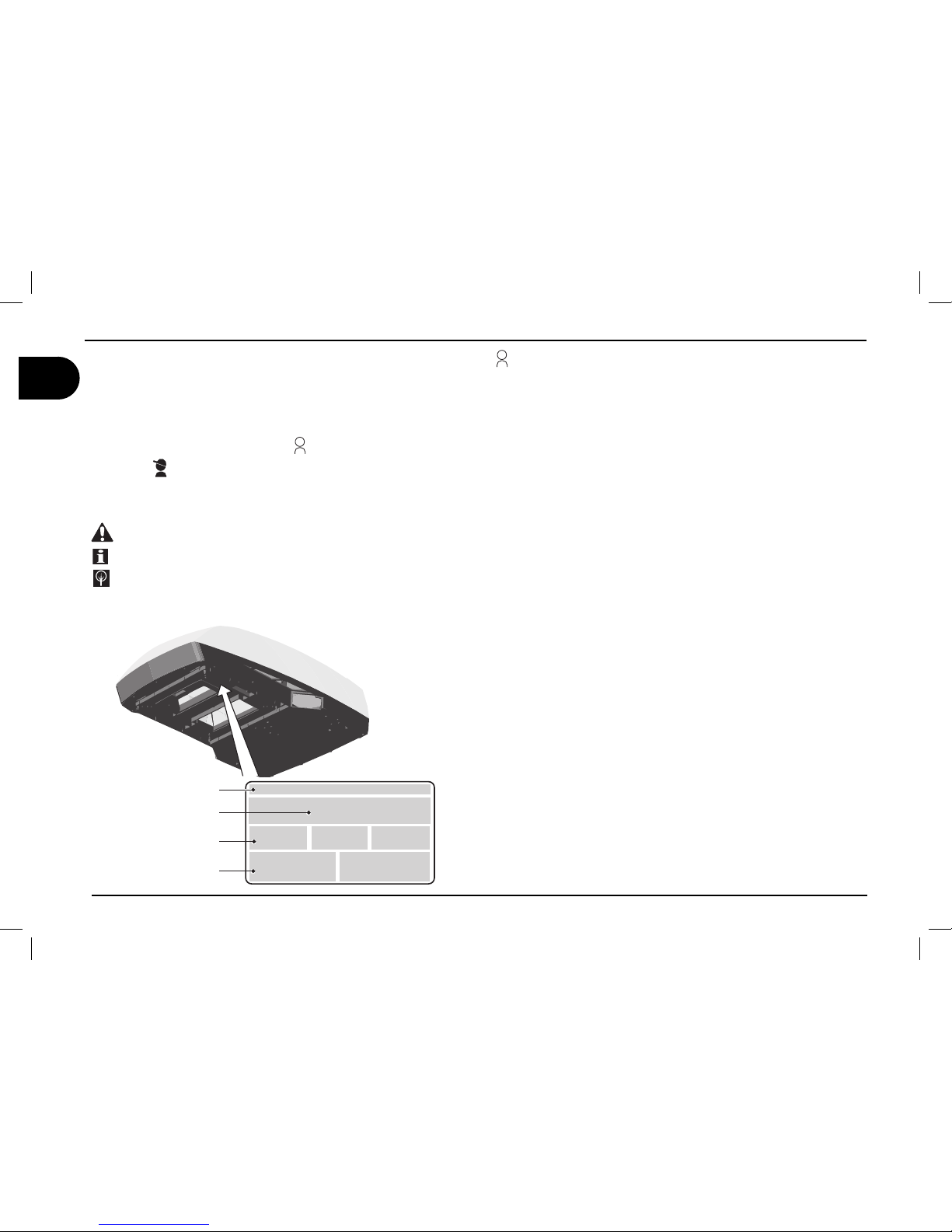
1.2. Manufacturer and air conditioner data plate
1.3. Description of the air conditioner
This air conditioner has been designed and manufactured to be installed
onto vehicles (i.e. camping-cars, caravans, motorhomes) to improve the
temperature conditions. It supplies fresh and dehumidifi ed air in summer
and warm air in winter without, in any case, replacing the heating system
of the vehicle. In both cases, temperature is set by the user.
Fresh air - Running
The system is inclusive of: compressor ( a ), condenser ( b ), evapora-
tor ( d ) and refrigerant gas under pressure. According to the physical
state of the refrigerant gas -i.e. liquid or gaseous, it heats or cools the
components where it passes through.
Fan ( c ) forces the internal air through the cooled evaporator from where
it comes out cooled down and dehumidifi ed.
This action, protracted over the time, reduces the temperature into
the vehicle.
Hot air – Description of operation
The refrigerant gas cycle can be inverted by a solenoid valve (f). The
heat accumulated by the refrigerant gas is dispersed by the internal
heat exchanger which uses the fan (c) to deliver the heat into the
passenger compartment. Over time, this increases the temperature
inside the vehicle.
1 General informations
Manufacturer
Conformity marking
Model/Serial number
Year of manufacture
Technical data
Page 7

users ‘ instructions
5
GB
B3000 PLUS
general informations 1
Compressor (a)
Condenser (b)
Evaporator (d)
Solenoid valve (f)
condensate draining
Fan (c)
Air drawn in from outside
Air drawn in from outside
warm air
discharged
conditioned air
drawn inside
the vehicle
Air drawn in from outside
warm air
discharged
air recirculated
inside the vehicle
Page 8
6
users ‘ instructions
GB
B3000 PLUS
1.4. How to use the air conditioner
The air conditioner performance can be improved by taking some
simple measures.
Improve the thermal insulation of the vehicle by closing any opening
and by covering any glassed surfaces with refl ecting curtains.
Avoid opening doors and windows unnecessarily.
Select the most suitable temperature and speed.
Properly direct the air fl aps.
To prevent troubles and minimise risks for people, take the following
precautions:
Do not obstruct the air inlets and outlets with cloths, paper or other
objects;
Do not introduce your hands or other objects into the openings;
Do not spray the air conditioner with water;
Keep fl ammable substances away from the air conditioner.
•
•
•
•
•
•
•
•
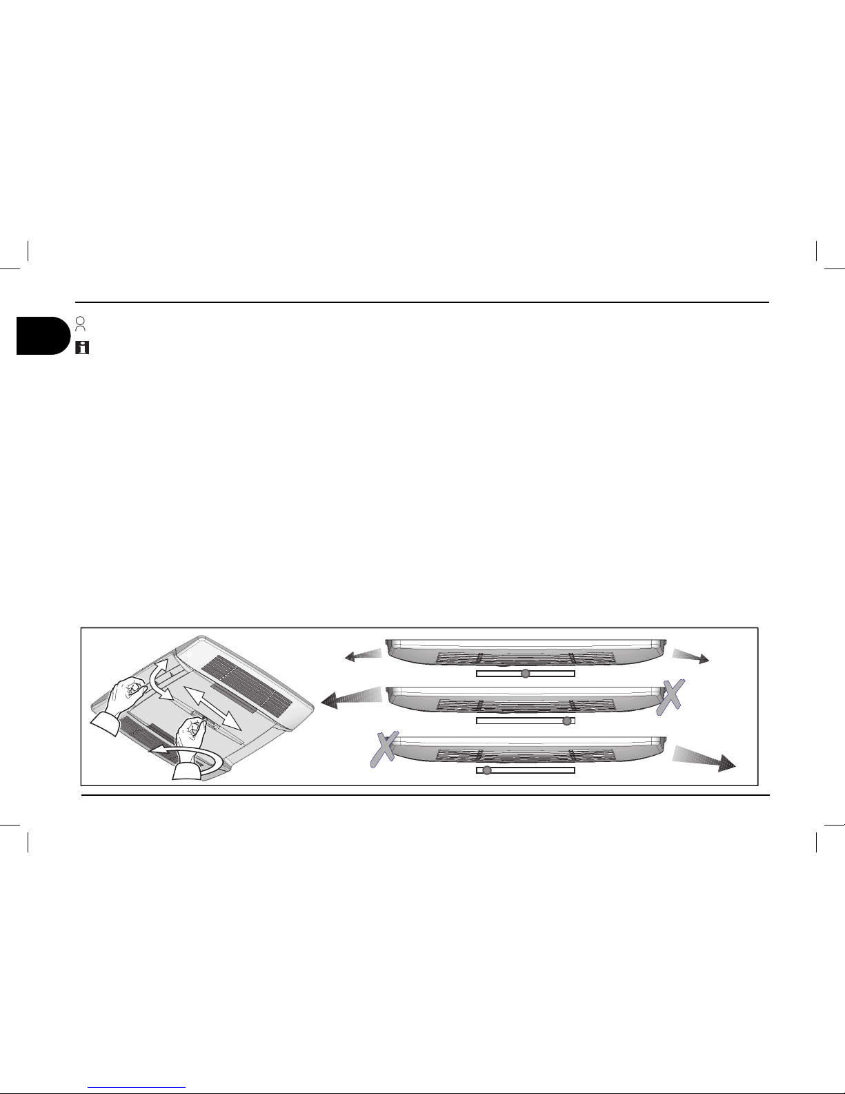
Adjusting the air direction
Position the air diffusing fl aps to direct the air to the desired position. In order to balance the airfl ow it’s necessary to rotate the center knob in
anticlockwise, to choose the wished position and then rotate clockwise.
1 general informations
Page 9
users ‘ instructions
7
GB
B3000 PLUS
general informations 1
* (only for models equipped with resistance) **(only for models equipped with light)
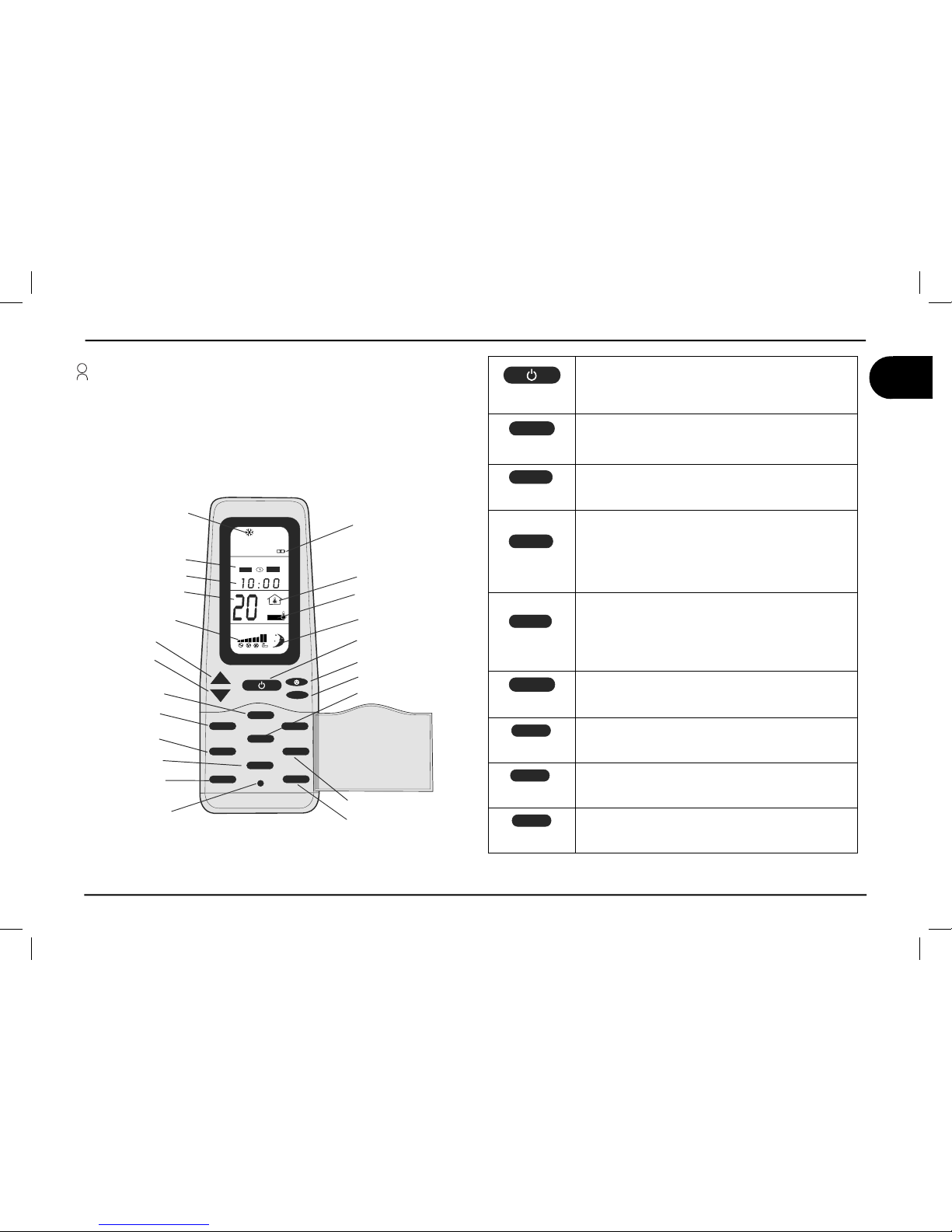
1.5.Description of the controls
+
-
MODE
¡$
Clock
Room
Se
t
REMOTE CONTROL
Clock Display
UP (+)
Down (-)
Reset Button
Room
Temperature
Operation Mode
Display Window
Fan Speed Display
F°/C°
Low Battery
Light
Fan
Mode
ON/OFF
Set Point
I Feel
Sleep
Timer
Timer
Sleep
I Feel
CLOCK
TIMER
SET
SLEEP
I FEEL
ROOM
F°/C°
LIGHT
LIGHT
IFEEL
IFEEL
0/
0''
ON/OFF
Press the ON/OFF button to start the airconditioner.
When it’s OFF all the symbols are OFF, except the
clock and you can use the ROOM and the LIGHT
buttons.
F°/C°
F°/C°
Choose the temperature measurement unit between
Celsius (°C) or Fahrenheit (°F).
If temperature is displayed this function is enabled.
LIGHT
LIGHT
LIGHT**
Pressing the light key the light on the airconditioner diffuser is switched on (if equipped) .The light button works
also when the remote control is off.
ROOM
ROOM
Pressing this button the room symbol is displayed and
the local temperature is displayed instead the set point.
Pressing the Room button an other time the Room
symbol disappear and the set point temperature is
displayed instead the local one.
This button works also when the remote control is off.
CLOCK
CLOCK
Pressing the “CLOCK” button for a time longer than 2
seconds, it is possible to modify the “TIME SETTING”,
managing the UP (+) button or the DOWN (-). Press
the “SET” button to confirm the modifications. After 15
seconds the new set is confirmed in any cases.
SET
SET
This button has two functions:
1) To confirm the TIME SETTING
2) To resend the actual operating setting
TIMER
TIMER
Press this button to set the time of automatic startup
and/or shutdown.
SLEEP
SLEEP
Press this button to activate the SLEEP function. The
set point is adjusted automatically to increase comfort
when sleeping.
I FEEL
I FEEL
Every 10 minutes the operating set point is adjusted to
the temperature detected by the remote control.
The RESET button erases all the configuration parameters to default.
Page 10

8
users ‘ instructions
GB
B3000 PLUS
1 general informations
* (only for models equipped with resistance) - **(only for models equipped with light)
AUTOMATIC MODE
¡$
AUTO
COOL / HEAT MODE
FAN MODE
¡$ ¡$
30%%$
30%%$
30%%$
30%%$
Available Fan speeds (Cool/Heat*/Fan Mode)
MODE
Press the MODE button.
Set to “AUTO”
+
-
Choose the Set Point
(16°C - 31°C)
In this mode the fan button is disabled.
You can use the LIGHT** and ROOM button.
MODE
Press the MODE button.
Set to “COOL” or “HEAT”*
+
-
Choose the Set Point
(16°C - 31°C)
Choose the Fan Speed
You can use the LIGHT** and ROOM
MODE
Press the MODE button.
Set to “FAN”
Choose the Fan Speed
You can use the LIGHT** and ROOM button.
Low battery
The low battery symbol will
appear in the display window
when the low battery condition
exists.
In this case after each
command, the “low voltage
symbol” flickers for 2 seconds.
In these 2 seconds the remote
control is not able to send other
commands.
BATTERYCOMPARTMENT
ON BACK SIDE OF REMOTE
CONTROL
1
234
O
F
F
OFF
Replace the batteries
2x1.5V AAA
Page 11

users ‘ instructions
9
GB
B3000 PLUS
TIMER
0/
0''
Note: Every time the timer button is pressed, the display fl ashes for 15 seconds while waiting for the settings
to be modifi ed. Remember to set the clock to the correct time before using this function.
Setting the “ON” timer (automatic startup)
1) Press the TIMER button and the ON clock will start to fl ash.
2) Set the time required using the + and - buttons
3) Point the remote control at the receiver and press the “SET” button to confi rm
Setting the “OFF” timer (automatic shutdown)
1) Press the TIMER button twice and the OFF clock will start to fl ash.
2) Set the time required using the + and - buttons
3) Point the remote control at the receiver and press the “SET” button to confi rm
Setting the “ON” & “OFF” timer (Automatic on/off)
1) Press the TIMER button three times and the ON clock will start to fl ash while the OFF clock is visible.
2) Set the required ON time using the + and - buttons
3) Press the TIMER button and set the required OFF time using the + and - buttons
4) Point the remote control at the receiver and press the “SET” button to confi rm
SLEEP
1) Select the required temperature.
2) Press the SLEEP button
Note: The SLEEP function lowers the set temperature by 1° after one hour and by 2° after
two hours.
I FEEL
1) Press the I FEEL button to enable the function.
2) Position the remote control so that it is possible to send signals to the receiver.
3) The operating temperature is adjusted to the temperature detected by the remote control.
Note: The remote control must not be in an area that is much warmer or much cooler than
the normal room temperature (e.g.: exposed to direct sunlight or to the cold air coming from
the diffuser.)
I FEEL
I FEEL
¡$
0/
0''
general informations 1
Page 12

10
users ‘ instructions
GB
B3000 PLUS
LED
1.5.Description of the led state on the airdiffuser
LED State Description
Off Airconditioner off
Orange
Airconditioner on StandBy (switch ON - aiconditioner is waiting for
a command)
Green Airconditioner is running
Red (fi xed)
Anomaly - 230V power supply missing (12V
is present)
Red (1 fl ick) Anomaly - Malfunctioning of the E1 temperature probe (internal)
Red (2 fl icks) Anomaly - Malfunctioning of the E2 temperature probe (external)
Red (3 fl icks) Anomaly - Malfunctioning of the E3 temperature probe (external)
Flashing green Defrost / Start heat pump
1 general informations
Page 13

users ‘ instructions
11
GB
B3000 PLUS
general informations 1
1.6. Technical data
Description Unit
Model
B3000 plus
Refrigerant gas (type/quantity) see date template
Nominal capacity KW
3,2
Cooling-Heating consumption W
1200-1350
Heating capacity KW
3,3
Electrical rating V-Hz
230-50
Protection degree IP
X4
Conditioned air volume m3/h
380
Max internal volume of the vehicle
(insulated walls)
m
3
30
Weight Kg
40.5
235
650
310
min 30
Page 14

12
users ‘ instructions
GB
B3000 PLUS
1.7. Ordinary maintenance
Cleaning; periodically clean the air conditioner and remove dust with a dump cloth. When
necessary, use a mild detergent. Do not use petrol or solvents.
Checks; regularly check the air conditioner and make sure that the water
outlet holes are not clogged.
Filters cleaning (1): periodically carry out this operation; wash the fi lters with a detergent solution and allow to dry before refi tting.
Active carbon fi lter (2): It’s recomended to change the active carbon fi lters every year.
Petrol
1 general informations
Page 15

users ‘ instructions
13
GB
B3000 PLUS
Installation instructions 2
The air conditioner must be installed by skilled technicians. In addition to this requirement, the people making the unit installation must make sure
that the working conditions are safe for everybody concerned.
2.1. Packaging, unpacking and handling
Always follow the instructions printed on the packaging.
Remove the air conditioner from its packaging and made sure that
it is not damaged.
Never use the rear air openings to lift the air conditioner
from its packaging
Move the air conditioner to the installation site under safe conditions.
Page 16

14
users ‘ instructions
GB
B3000 PLUS
To install the air conditioner, the roof shall have an opening of suitable sizes. It is possible to use an existing air inlet or make a new
one.
According to the vehicle dimensions and depending on the air
conditioning needs, one or more units can be installed. The air
conditioner must be installed right in the middle with respect to the
vehicle Width and length.
Before installing the unit, make sure that the opening does not
interfere with the existing furnishing (lamps, wardrobes, doors,
curtains, etc.). This check allows for an easy mounting of the air
conditioner and a troublefree air circulation.
contact the vehicle manufacturer and make sure that the
roof structure can tolerate the static load and the stress transmitted vehicle, especially under running conditions. Sometimes vehicle manufacturers previously arrange areas for the
unit installation weakening and/or electric cable from being
cut.
The air conditioner should preferably be installed on a
level plane. Maximum allowed inclination: 10°.
2.2. Preparing the roof opening
2 Installation instructions
Page 17

users ‘ instructions
15
GB
B3000 PLUS
Danger of electrical hazards.
Turn all power sources off
Using an existing opening
Remove the skylight cover.
Clean the installation opening all around
by removing any adhesive residues.
Fill any existing screw hole or deformation
with fi ller or silicone.
1.
2.
3.
Installation instructions 2
Page 18

16
users ‘ instructions
GB
B3000 PLUS
New installation opening
Using the printed cardboard template supplied with the unit, fi nd the position and di-
mensions of the new opening.
Drill the four corners.
Cut by joining the previously made holes.
If necessary, mount a reinforcing wooden
frame.
1.
2.
3.
4.
Drill a hole for the
supply cables
2 Installation instructions
Page 19

users ‘ instructions
17
GB
B3000 PLUS
Installation instructions 2
2.3. Mounting the air conditioner
Set the air conditioner onto the roof opening. Never slide the air conditioner on
the roof, but lift when moving it.
Note: the conical pins under the base
must enter the roof openings.
Fix the air diffuser brackets to the base
using the 4 screws provided.
Always tighten to the recommended torque wrench setting. Do not overtighten!
Mount the airdiffuser linking gaskets.
For correct thickness follow the table on
page 19.
Do the electrical connection as described
in paragraph 2.4.
Page 20

18
users ‘ instructions
GB
B3000 PLUS
2 Installation instructions
Fix the cooling unit to the brackets using
the 4 screws provided.
Mount the fi lters in the order shown in
fi gure.
Mount the fi lters covers.
THICKNESS OF THE ROOF THICKNESS OF THE GASKET
= 30 mm 10 mm
from 30 to 35 mm 15 mm
from 35 to 40 mm 20 mm
from 40 to 45 mm 25 mm
from 45 to 50 mm 30 mm
from 50 to 55 mm 35 mm
from 55 to 60 mm 40 mm
from 60 to 65 mm 45 mm
from 65 to 70 mm 50 mm
from 70 to 75 mm 55 mm
from 75 to 80 mm 60 mm
Page 21

users ‘ instructions
19
GB
B3000 PLUS
Installation instructions 2
2.4. Electric connection
For the electric connections, always follow the national and local regulations
Arrange a specifi c electric system
Connect the wires to the air conditioner. Connect the electric system to a circuit supplying the required power
(see technical data) and fi tted with a good ground system.
B2200
REWOPCIRTCEL%
R
OTARENEG
HCTIWSREVOçEGNAH#
ROTARENEGSNIAM
SNIAMYLPPU3
SUOIRA
6
SRESU
ESU
&
XOB
YLP
PUSREWOPRENOITIDNOCRI!
HTG
NE,
M
NOITCESçSSOR#
M
M
,
QPMFDPOOFDUPS
GSPNBJSDPOEJUJPOFS
CBTF
QPMFDPOOFDUPSPO
UIFFMFDUSPOJDEFWJDF
JOTJEFBJSEJõVTFS
12V DC
#SPXOXJSF
#SPXOXJSF
230V 50Hz
10-&#"55&3:
10-&#"55&3:
$ZBOXJSF
$ZBOXJSF
(SFFO:FMMPXXJSF
(SFFO:FMMPXXJSF
Page 22

20
users ‘ instructions
GB
B3000 PLUS
SOLUTION
temperature less than 18°C
temperature over 40°C
check the set point temperature
defective thermal protection
switch wrongly positioned
defective heating resistance
refrigerant gas is not enough
damaged compressor
thermal exchange batteries are dirty
defective internal fan
air fi lter is clogged
defective external fan
water outlet holes are clogged
damaged sealing gasket
no power supply
low power supply (less than 200V)
defective capacitor
defective thermal protection
CAUSA
the air conditioner does not cool suffi ciently
the air conditioner does not heat enough
no air circulation into the vehicle
water leaks into the vehicle
the air conditioner does not start
the air conditioner stops running
Operations to be carried
out by the user
Operations to be carried out
by authorised personnel
3.1. Troubles, causes, solutions
3.2. Extraordinary maintenance
For the best performance of your air conditioner, have your dealer/workshop clean it thoroughly before use:
thermal exchange batteries
water outlet holes are properly cleaned.
1.
2.
3 Troubleshooting, maintenance, recycling
Page 23

users ‘ instructions
21
GB
B3000 PLUS
12
17
1
3
47
2
19
10
32
7
8
15
11
21
6
9
5
30
28
31
24
23
13
14
29
18
22
48
49
4
33
16
25
20
26
27
34
35
36
37
38
39
40
41
42
43
44
45
46
Spare part list
Page 24

22
users ‘ instructions
GB
B3000 PLUS
N. DESCRPTION
1 PAN BASE
2 COVER
3 RIVETS TWO STAGE
4 VIBRATION DAMPER
5 SUPPORT
6 SUPPORT
7 COMPRESSOR
8 CAPASITOR
9 VIBRATION DAMPER
10 COMPRESSOR WIRING
11 EVAPORATOR
12 FAN
13 SOLENOID VALVE
14 RETURN PIPE
15 DELIVERY PIPE
16 LED BOARD
17 OR GASKET
18 SUPPORT
19 LABEL
20 SUPPORT
21 WIRING
22 PLENUM
23 FAN SUPPORT
24 FAN
25 RELAY BOARD
26 FILTER
27 ACTIV CARBON FILTER
28 CONDENSER
29 PIPE
30 PIPE
31 CAPILLARY TUBE
32 HEAT INSULATOR BOX
33 AIR DIFFUSER BASE
34 AIR DIFFUSER FLAP
35 GRILLE
36 DEFLECTOR SLIDE
37 KNOB
38 COVER
39 RECEIVER BOARD
40 RECEIVER COVER
41 LABEL
42 FIXING BRACKET
43 GASKET
44 GASKET
45 GASKET
46 SCREW
47 LABEL
48 EXTERNAL PROBE
49 INTERNAL PROBE
N. DESCRPTION N. DESCRPTION
Spare part list
Page 25

users ‘ instructions
23
GB
B3000 PLUS
WIRING DIAGRAM
NWORB
EUL
B
NEERG-WOLLEY
CA
V032
LARTUEN - 2T
*
ENIL - 1
T
*
123
DNUORG - 3T
*
121
2
D
ER
NEERG
NAYC
WOLL
E
Y
NWORB
E
TIH
W
CKAL
B
EUL
B
YARG
TE
LOIV
RED
GREEN
CYAN
YELLOW
BROWN
WHITE
BLAK
BLUE
GRAY
VIOLET
xJ
1
2
3
4
5
6
7
8
9
01
3C3C
1234567891011
12
xJ
xC
1
2
Led
board
xJ
xC
1
2
Led
board
xJ
xC
1
2
Led
board
xJ
xC
1
2
Led
board
AIR DIFFUSER
VALVE
ORANGE
0/0''
0/0''
&$0/0.:
&$0/0.:
*/7&35&3
*/7&35&3
OPTIONAL CONNECTION
TO SWITCH ON THE AIR
DIFFUSER LIGHT ALSO
WHEN THERE IS NO MAIN.
PLEASE USE THE
PROVIDED CONNECTOR
PLUGGED IN THE BOARD
EUL
B
N
E
E
RG-WO
L
L
E
Y
D
E
R
KN
I
P
HCTIWS OMRET HCTIWS OMRET
*
2F2F
*
123
*
4F4F
*
2
x
O 2xO
*
*
5F5F
*
Fuxx Fuxx
1xO1
xO
*
1F1F
*
*
3F3F
**
*
*
1
2
3
4
COMPRESSOR
N
EERG-W
O
LLE
Y
N
EE
R
G-W
O
L
L
E
Y
K
C
A
L
B
NW
O
RB
EU
LB
1
2
3
4
FAN2 CONDERNSER
N
EE
R
G-W
O
L
L
E
Y
K
C
A
L
B
NW
O
RB
EU
LB
123
4
FAN1 CONDERNSER
KCALB
NWO
R
B
EUL
B
FAN EVAPORATOR
+ 12vdc BATTERY
- BATTERY
TEMPERATURE
PROBE
BATTERY
FUSE F2AL250V
MAIN FUSE F10AL250V
."*/'64&
."*/'64&
#"55&3:'64&
#"55&3:'64&
&7"1130#&
&7"1130#&
$0/%130#&
$0/%130#&
#"55&3:
#"55&3:
"694&3*"-
"694&3*"-
$0/%'"/
$0/%'"/
$0/%'"/
$0/%'"/
&7"1'"/
&7"1'"/
)00%
)00%
."*/
."*/
$0.13&4403
$0.13&4403
7"-7&
7"-7&
3&.05&
3&.05&
3&.05&
3&.05&
+
+
Page 26

Page 27

Page 28

Via Virgilio, 3 - 47122 Forlì - Tel. 0543/754901 Fax. 0543/756631
DOMETIC ITALY s.p.a.
Cod. ST 0117 R.1
 Loading...