

Page 1
Operation, maintenance and installation manual
Libretto istruzioni per l’uso, la manutenzione e l’installazione
Betriebs-, Wartungs- und Installationsanleitung
Manuel d’utilisation, d’entretien et d’installation
Bedienings-, onderhouds- en installatiehandleiding
Manual de instrucciones para el uso, mantenimiento e instalación
Manual de instruções de uso, manutenção e instalação
Handbok för användning, underhåll och installation
Käyttö-, huolto- ja asennusohje
Bruks- vedlikeholds- og installasjonsanvisning
Betjenings-, vedligeholdelses- og installationsvejledning
Page 2

ENGLISH
With Dometic at home everywhere. Thank you for your decision to buy an Dometic product.
They all have been specially conceived for your vehicle, matching totally the requirements of
leisure on wheels - with more than 75 years of experience, the most advanced technology,
fi rst-rate materials, superb workmanship, functional design and a care for the environment.
The unique Dometic EuroService Guarantee offers you additional peace of mind - ensuring
that you will derive comfort everywhere from your Dometic products
ITALIANO
Con Dometic come a casa, ovunque. Vi ringraziamo per averci scelto. I prodotti Dometic
sono stati espressamente concepiti per il Vostro veicolo; soddisfacendo completamente le
esigenze del tempo libero, sui mezzi mobili, con un’esperienza di oltre 75 anni, la tecnologia
più avanzata, materiali di prima qualità, superba squadra di tecnici nonché design funzionale ed attenzione per l’ambiente. Usufruite del Servizio di Garanzia Europea che Vi offre
completa tranquillità assicurandoVi che trarrete grande comfort ovunque grazie ai “Vostri”
prodotti Dometic
DEUTSCH
Mit Dometic überall wie zu Hause. Wir danken Ihnen für Ihre Wahl. Die Dometic-Produkte
wurden speziell für Ihr Fahrzeug entwickelt und tragen den Erfordernissen der Freizeit auf
Rädern voll Rechnung - mit einer mehr als 75-jährigen Erfahrung, modernster Technologie,
erstklassigen Materialien, einem hervorragenden Technikerteam, funktionellem Design und
Umweltfreundlichkeit. Nutzen Sie die EuroService-Garantie, mit der Sie ganz ruhig fahren und
die Ihnen überall dank “Ihren” Dometic-Produkten größten Komfort sichert
FRANÇAIS
Partout avec Dometic. Merci d’avoir choisi un produit Dometic. Il a été spécialement conçu
pour votre véhicule complétant totalement la gamme d’équipements de votre véhicule de loisirs.
Dometic, c’est aussi, 75 ans d’expérience, une technologie avancée, du matériel de premier
choix, un design fonctionnel et la protection de l’environnement. La garantie Européenne
Dometic vous offre, où que vous soyez, la possibilité de profi ter partout de votre matériel.
NEDERLANDS
Met Dometic voelt u zich overal thuis. Wij danken u voor uw besluit een product van Do-
metic aan te schaffen. Al onze producten zijn speciaal ontworpen voor uw voertuig en voldoen
volledig aan de vereisten die worden gesteld aan een vakantie onderweg - met meer dan
75 jaar ervaring, de meest geavanceerde technologie, uitstekende materialen, voortreffelijk
vakmanschap, functioneel design en zorg voor het milieu. Bovendien biedt de unieke Dometic
EuroService Garantie u extra zekerheid - zodat u er zeker van bent dat u overal kunt genieten
van het comfort die producten van Dometic u bieden.
ESPAÑOL
Con Dometic en todas partes como en casa. Le agradecemos su elección.
Los productos Dometic han sido expresamente concebidos para su vehículo; satisfaciendo
totalmente las exigencias del tiempo libre, en medios móviles, con una experiencia de más
de 75 años, la tecnología más avanzada, materiales de primera calidad, soberbio equipo
de técnicos así como design funcional y respeto al medio ambiente. Disfruten del Servicio
de Garantía Europea que le ofrece tranquilidad absoluta, asegurándole que obtendrá gran
confort en cualquier lugar gracias a sus productos Dometic.
PORTUGUÊS
Com Dometic, em todo o lado como em casa. Agradecemos a sua escolha. Os produtos
Dometic foram expressamente concebidos para o seu veículo; satisfazendo totalmente as
exigências do tempo livre, em meios móveis, com uma experiência de mais de 75 anos, a
tecnologia mais avançada, materiais de primeira qualidade, uma excelente equipa de técnicos
e um design funcional e respeito pelo ambiente. Aproveite o Serviço de Garantia Europeia,
que lhe oferece uma tranquilidade absoluta e lhe assegura que obterá um grande conforto
em qualquer lugar graças aos seus produtos Dometic.
SVENSKA
Med Dometic är Du hemma överallt. Tack för Ditt beslut att köpa en Dometicprodukt. De
har utvecklats speciellt för Din husvagn eller husbil och lever upp till alla de krav för fritid på
hjul -med mer än 75 års erfarenhet, avancerad teknologi, förstklassigt material, oöverträffat
hantverk och design samt omtanke om miljön. Den unika Dometic Europagararantin ger Dig
trygghet om något skulle hända.
SUOMI
Dometic - kotonaan kaikkialla. Olemme iloisia siitä, että olet valinnut Dometic tuotteen.
Tuotteemme on kehitetty yli 75 vuoden kokemuksella liikkuvan lomanviettäjän tarpeisiin ja
valmistettu ensiluokkaisista materiaaleista uusimmalla, ympäristöä säästävällä tekniikalla,
toimivalla muotoilulla ja korkealla ammattitaidolla. Dometic tuotteita voit käyttää luottavaisin
mielin.Ainutlaatuinen Dometic EuroService -takuu ja laaja huoltoverkosto varmistavat., että
saat apua ongelmatilanteissa myös matkasi varrella.
NORSK
Med Dometic kan du føle deg hjemme overalt. Takk for at du bestemte deg for å kjøpe
et produkt fra Dometic. Alle våre produkter er utviklet spesielt for ditt kjøretøy og lever fullt
opp til alle krav om bekvemmelighet i din fritid - basert på mer enn 75 års erfaring, den mest
avanserte teknologi, førsteklasses materialvalg og håndverk, funksjonelt design og omtanke
for miljøet. Den unike Dometic EuroService-garantien gir deg trygghet og sikrer komfort
uansett hvor du måtte befi nne deg.
DANSK
Med Dometic kan du føle dig hjemme overalt. Tak for din beslutning om at købe et Dometic
produkt. De er alle blevet specielt udviklet til dit køretøj og lever fuldt ud op til kravene om
fritid på hjul med mere end 75 års erfaring, den mest avancerede teknologi, førsteklasses
materialer, uovertruffent håndværk, funktionelt design og omtanke for miljøet. Den unikke
Dometic EuroService Garanti giver dig yderligere ro i sjælen og sikrer, at du takket være dine
Dometic produkter vil opleve stor komfort, uanset hvor du befi nder dig.
Page 3

Warranty Validity
‘The product is warranted in accordance with the enforced Law and regulations implementing the Directive
1999/44/EC.
The Manufacturer s warranty does not extend to Product failures, defects or damage arising from and/or attributable to a wrong installation.
The Consumer is entitled to let the Product be installed by an authorised dealer, not bound by Dometic.
©DOMETIC - 2009 All rights reserved - Printed in Italy
No part of this publication may be reproduced, copied or transmitted in any
form or by any means without prior written permission from DOMETIC.
Figures, descriptions, references and technical data in this manual are given
as mere example and are not binding.
In pursuing a policy of continual product and safety improvement, DOMETIC
reserves the right to make changes at any time without undertaking to give
prior notice or to update this manual every time.
Keep this document for future reference.
Page 4

Regulations for environmental safety and correct disposal
All organisations must apply a set of procedures to identify, evaluate and control the infl uence that their activities (manufacturing, products, services,
etc.) have on the environment.
The procedures to be followed to identify signifi cant environmental impact must take the following factors into account:
- use of raw materials and natural resources
- atmospheric emissions
- discharge of liquids
- waste management and recycling
- contamination of the soil
In order to minimise environmental impact, the manufacturer provides a series of indications here below that should be taken into account by all those
who, for whatever reason, interact with the appliance during its working life.
- all packing components must be disposed of (preferably recycled) in compliance with statutory legislation in the country in which disposal
takes place
- all product components must be disposed of (preferably recycled) in compliance with statutory legislation in the country in which disposal
takes place
- for correct disposal, the appliance must be consigned to an authorised waste disposal company to ensure that all recyclable components
are reused and the remaining materials are processed properly
- during installation ensure the room has adequate ventilation to prevent the build-up of stale air that might be harmful to the health of the
operators
- during operation and maintenance ensure that any waste pollutant products
(oil, grease, etc.) are disposed of correctly
- keep noise levels down to reduce noise pollution
For more information on correct dismantling of our products please refer to the recycling handbooks at www.dometic.com/ambiente.........
Page 5

1 General informations
1.1. Scope of the manual.............................................4
1.2. Manufacturer and air conditioner data plate......4
1.3. Description of the air conditioner..........................4
1.4. How to use the air conditioner....................................8
1.5. Description of the controls................................... 9
1.6. Technical data................................................ 14
1.7. Ordinary maintenance....................................15
2 Installation instructions
2.1. Packaging, unpacking and handling..............16
2.2. Preparing the roof opening........................17
2.3. Mounting the air conditioner...........................20
2.4. Electric connection......................................22
3 Troubleshooting, maintenance, recycling
3.1. Troubles, causes, solutions..............................23
3.2. Extraordinary maintenance..............................23
3.3. Recycling......................................................23
Spare part list .............................................24
WIRING DIAGRAM .............................................28
Index
Operation, Maintenance and
Installation manual
Air conditioner
GB
I
D
F
Handleiding voor bediening,
onderhoud en installatie
Airconditioner
NL
Manual de instrucciones para el uso, la manutención
y la instalación
Acondicionator
E
Livrete de instruções para uso, manutenção
e instalação
Aparelho de ar condicionado
P
Handbok för drift, underhåll och
installation
Luftkonditionering
S
Käyttö-, huolto- ja
asennusohje
Ilmastointilaite
FIN
Brukerveiledning og manual
til vedlikehold og installasjon
Airconditioner
N
DK
Libretto istruzioni per l’uso, la manutenzione e
l’installazione
Condizionatore
Bedienungs- und
Wartungsanleitung
Klimaanlage
Mise en route, entretien et
installation
Climatiseur
Brugervejledning og manual
til vedligeholdelse og installation
Airconditioner
Page 6
4
users ‘ instructions
GB
B1600 - B1600PLUS - B2200 - B2600
1.1. Scope of the manual
This manual has been made by the Manufacturer and it shall be regarded
as part of the air conditioner.
The information it contains, when complied with, ensures a correct and
effi cient use of the air conditioner.
The fi rst part of this manual is for users
, the second one for qualifi ed
technicians facing the installation of the air conditioner.
To draw the readers attention to special parts of the text, the following
symbols have been used:
This operation may result in dangers
Useful advice
Environment safety related information
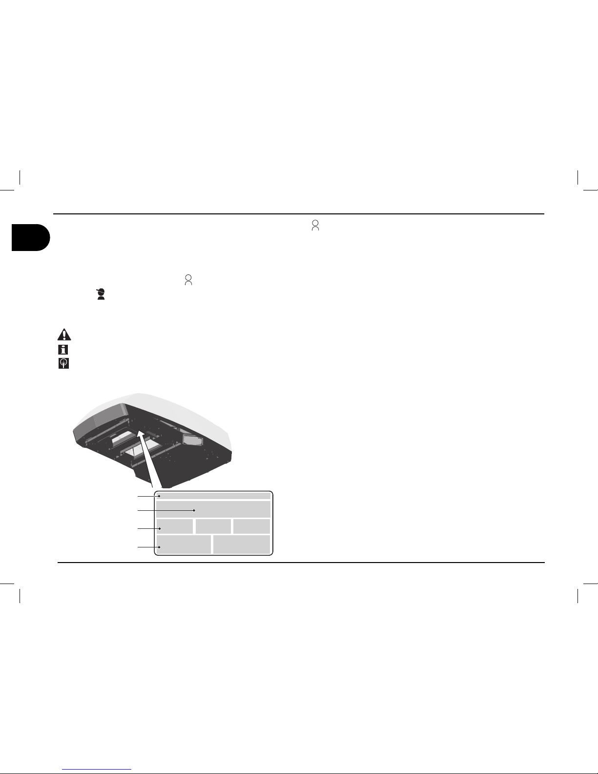
1.2. Manufacturer and air conditioner data plate
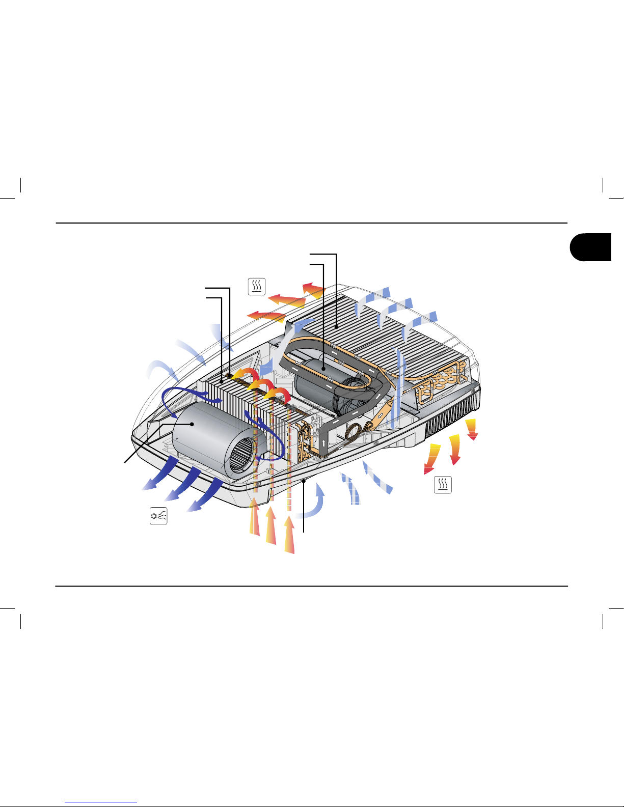
1.3. Description of the air conditioner
(B1600 B1600PLUS B2200)
This air conditioner has been designed and manufactured to be installed
onto vehicles (i.e. camping-cars, caravans, motorhomes) to improve the
temperature conditions. It supplies fresh and dehumidifi ed air in summer
and warm air in winter without, in any case, replacing the heating system
of the vehicle. In both cases, temperature is set by the user.
Fresh air - Running
The system is inclusive of: compressor ( a ), condenser ( b ), evaporator ( d ) and refrigerant gas under pressure. According to the physical
state of the refrigerant gas -i.e. liquid or gaseous, it heats or cools the
components where it passes through.
Fan ( c ) forces the internal air through the cooled evaporator from where
it comes out cooled down and dehumidifi ed.
This action, protracted over the time, reduces the temperature into
the vehicle.
Warm air - Running
Ambient air is forced by fan ( c ) into an electrical heating resistance
( e ) and then recirculated inside the vehicle.
1 General informations
Manufacturer
Conformity marking
Model/Serial number
Year of manufacture
Technical data
Page 7
users ‘ instructions
5
GB
B1600 - B1600PLUS - B2200 - B2600
general informations 1
Compressor (a)
Condenser (b)
Evaporator (d)
Resistance (e)
condensate draining
Fan (c)
Air drawn in from outside
Air drawn in from outside
warm air
discharged
conditioned air
drawn inside
the vehicle
Air drawn in from outside
warm air
discharged
air recirculated
inside the vehicle
Page 8

6
users ‘ instructions
GB
B1600 - B1600PLUS - B2200 - B2600
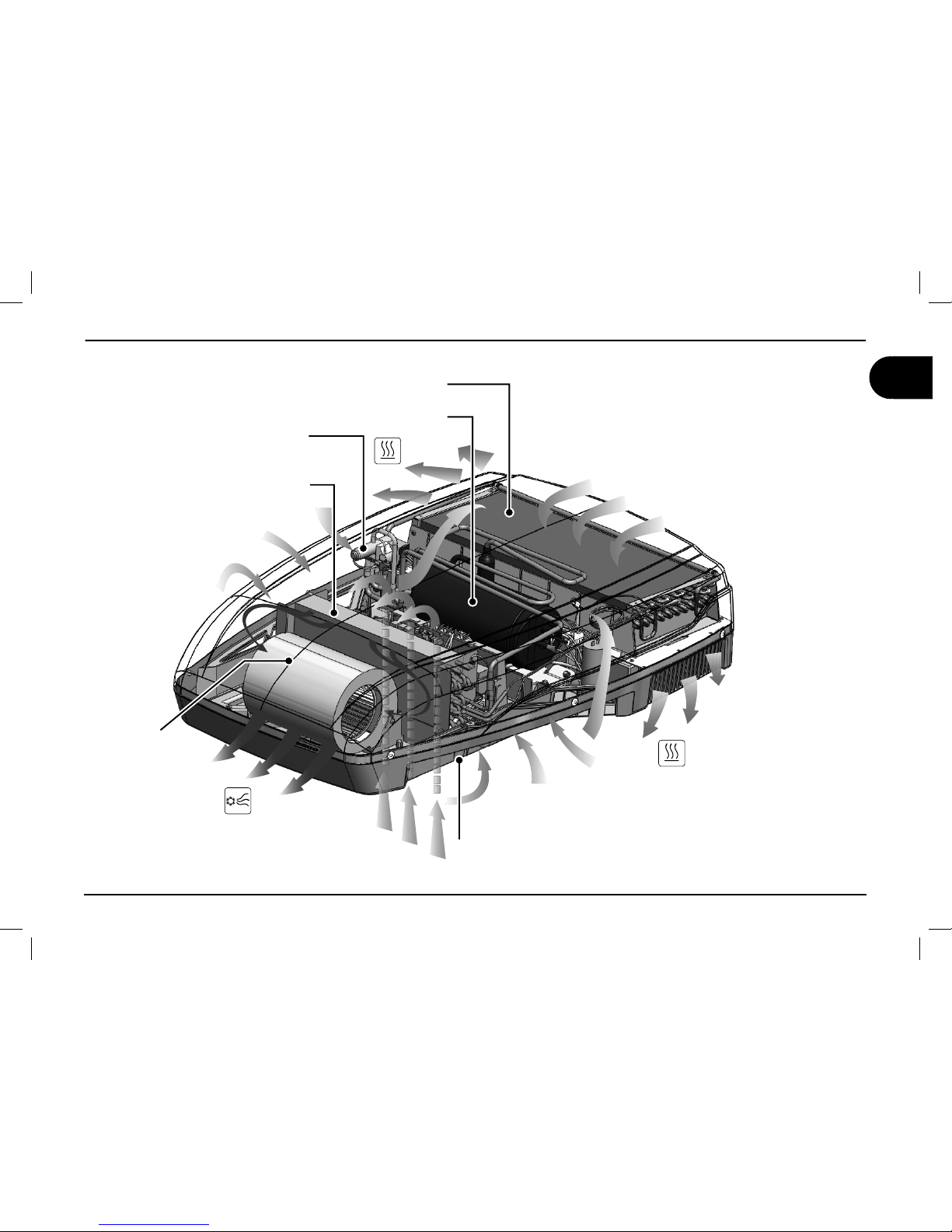
1.3. Description of the air conditioner (B2600)
This air conditioner has been designed and manufactured to be installed
onto vehicles (i.e. camping-cars, caravans, motorhomes) to improve the
temperature conditions. It supplies fresh and dehumidifi ed air in summer
and warm air in winter without, in any case, replacing the heating system
of the vehicle. In both cases, temperature is set by the user.
Fresh air - Running
The system is inclusive of: compressor ( a ), condenser ( b ), evaporator ( d ) and refrigerant gas under pressure. According to the physical
state of the refrigerant gas -i.e. liquid or gaseous, it heats or cools the
components where it passes through.
Fan ( c ) forces the internal air through the cooled evaporator from where
it comes out cooled down and dehumidifi ed.
This action, protracted over the time, reduces the temperature into
the vehicle.
Hot air – Description of operation
The refrigerant gas cycle can be inverted by a solenoid valve (f). The
heat accumulated by the refrigerant gas is dispersed by the internal
heat exchanger which uses the fan (c) to deliver the heat into the
passenger compartment. Over time, this increases the temperature
inside the vehicle.
Page 9
users ‘ instructions
7
GB
B1600 - B1600PLUS - B2200 - B2600
general informations 1
Compressor (a)
Condenser (b)
Evaporator (d)
Solenoid valve (f)
condensate draining
Fan (c)
Air drawn in from outside
Air drawn in from outside
warm air
discharged
conditioned air
drawn inside
the vehicle
Air drawn in from outside
warm air
discharged
air recirculated
inside the vehicle
Page 10

8
users ‘ instructions
GB
B1600 - B1600PLUS - B2200 - B2600
1.4. How to use the air conditioner
The air conditioner performance can be improved by taking some
simple measures.
Improve the thermal insulation of the vehicle by closing any opening
and by covering any glassed surfaces with refl ecting curtains.
Avoid opening doors and windows unnecessarily.
Select the most suitable temperature and speed.
Properly direct the air fl aps.
To prevent troubles and minimise risks for people, take the following
precautions:
Do not obstruct the air inlets and outlets with cloths, paper or other
objects;
Do not introduce your hands or other objects into the openings;
Do not spray the air conditioner with water;
Keep fl ammable substances away from the air conditioner.
•
•
•
•
•
•
•
•
Adjusting the air direction
Position the air diffusing fl aps to direct the air to the desired position. In order to balance the airfl ow it’s necessary to rotate the center knob in
anticlockwise, to choose the wished position and then rotate clockwise.
1 general informations
Page 11
users ‘ instructions
9
GB
B1600 - B1600PLUS - B2200 - B2600
*
* (only for models equipped with resistance)
1.5.Description of the controls (B1600)
Page 12
10
users ‘ instructions
GB
B1600 - B1600PLUS - B2200 - B2600
* (only for models equipped with resistance) **(only for models equipped with light)
1.5.Description of the controls
1 general informations
Remote control (B2200 B1600PLUS B2600)
+
-
MODE
¡$
Clock
Room
Set
REMOTE CONTROL
Clock Display
UP (+)
Down (-)
Reset Button
Room
Temperature
Operation Mode
Display Window
Fan Speed Display
F°/C°
Low Battery
Light
Fan
Mode
ON/OFF
Set Point
I Feel
Sleep
Timer
Timer
Sleep
I Feel
CLOCK
TIMER
SET
SLEEP
I FEEL
ROOM
F°/C°
LIGHT
LIGHT
IFEEL
IFEEL
0/
0''
ON/OFF
Press the ON/OFF button to start the airconditioner.
When it’s OFF all the symbols are OFF, except the
clock and you can use the ROOM and the LIGHT
buttons.
F°/C°
F°/C°
Choose the temperature measurement unit between
Celsius (°C) or Fahrenheit (°F).
If temperature is displayed this function is enabled.
LIGHT
LIGHT
LIGHT**
Pressing the light key the light on the airconditioner diffuser is switched on (if equipped) .The light button works
also when the remote control is off.
ROOM
ROOM
Pressing this button the room symbol is displayed and
the local temperature is displayed instead the set point.
Pressing the Room button an other time the Room
symbol disappear and the set point temperature is
displayed instead the local one.
This button works also when the remote control is off.
CLOCK
CLOCK
Pressing the “CLOCK” button for a time longer than 2
seconds, it is possible to modify the “TIME SETTING”,
managing the UP (+) button or the DOWN (-). Press
the “SET” button to confirm the modifications. After 15
seconds the new set is confirmed in any cases.
SET
SET
This button has two functions:
1) To confirm the TIME SETTING
2) To resend the actual operating setting
TIMER
TIMER
Press this button to set the time of automatic startup
and/or shutdown.
SLEEP
SLEEP
Press this button to activate the SLEEP function. The
set point is adjusted automatically to increase comfort
when sleeping.
I FEEL
I FEEL
Every 10 minutes the operating set point is adjusted to
the temperature detected by the remote control.
The RESET button erases all the configuration parameters to default.
Page 13
users ‘ instructions
11
GB
B1600 - B1600PLUS - B2200 - B2600
general informations 1
* (only for models equipped with resistance) - **(only for models equipped with light)
AUTOMATIC MODE
¡$
AUTO
COOL / HEAT MODE
FAN MODE
¡$ ¡$
30%%$
30%%$
30%%$
30%%$
Available Fan speeds (Cool/Heat*/Fan Mode)
MODE
Press the MODE button.
Set to “AUTO”
+
-
Choose the Set Point
(16°C - 31°C)
In this mode the fan button is disabled.
You can use the LIGHT** and ROOM button.
MODE
Press the MODE button.
Set to “COOL” or “HEAT”*
+
-
Choose the Set Point
(16°C - 31°C)
Choose the Fan Speed
You can use the LIGHT** and ROOM
MODE
Press the MODE button.
Set to “FAN”
Choose the Fan Speed
You can use the LIGHT** and ROOM button.
Low battery
The low battery symbol will
appear in the display window
when the low battery condition
exists.
In this case after each
command, the “low voltage
symbol” flickers for 2 seconds.
In these 2 seconds the remote
control is not able to send other
commands.
BATTERYCOMPARTMENT
ON BACK SIDE OF REMOTE
CONTROL
1
234
O
F
F
OFF
Replace the batteries
2x1.5V AAA
Page 14
12
users ‘ instructions
GB
B1600 - B1600PLUS - B2200 - B2600
TIMER
0/
0''
Note: Every time the timer button is pressed, the display fl ashes for 15 seconds while waiting for the settings
to be modifi ed. Remember to set the clock to the correct time before using this function.
Setting the “ON” timer (automatic startup)
1) Press the TIMER button and the ON clock will start to fl ash.
2) Set the time required using the + and - buttons
3) Point the remote control at the receiver and press the “SET” button to confi rm
Setting the “OFF” timer (automatic shutdown)
1) Press the TIMER button twice and the OFF clock will start to fl ash.
2) Set the time required using the + and - buttons
3) Point the remote control at the receiver and press the “SET” button to confi rm
Setting the “ON” & “OFF” timer (Automatic on/off)
1) Press the TIMER button three times and the ON clock will start to fl ash while the OFF clock is visible.
2) Set the required ON time using the + and - buttons
3) Press the TIMER button and set the required OFF time using the + and - buttons
4) Point the remote control at the receiver and press the “SET” button to confi rm
SLEEP
1) Select the required temperature.
2) Press the SLEEP button
Note: The SLEEP function lowers the set temperature by 1° after one hour and by 2° after
two hours.
I FEEL
1) Press the I FEEL button to enable the function.
2) Position the remote control so that it is possible to send signals to the receiver.
3) The operating temperature is adjusted to the temperature detected by the remote control.
Note: The remote control must not be in an area that is much warmer or much cooler than
the normal room temperature (e.g.: exposed to direct sunlight or to the cold air coming from
the diffuser.)
I FEEL
I FEEL
¡$
0/
0''
Page 15
users ‘ instructions
13
GB
B1600 - B1600PLUS - B2200 - B2600
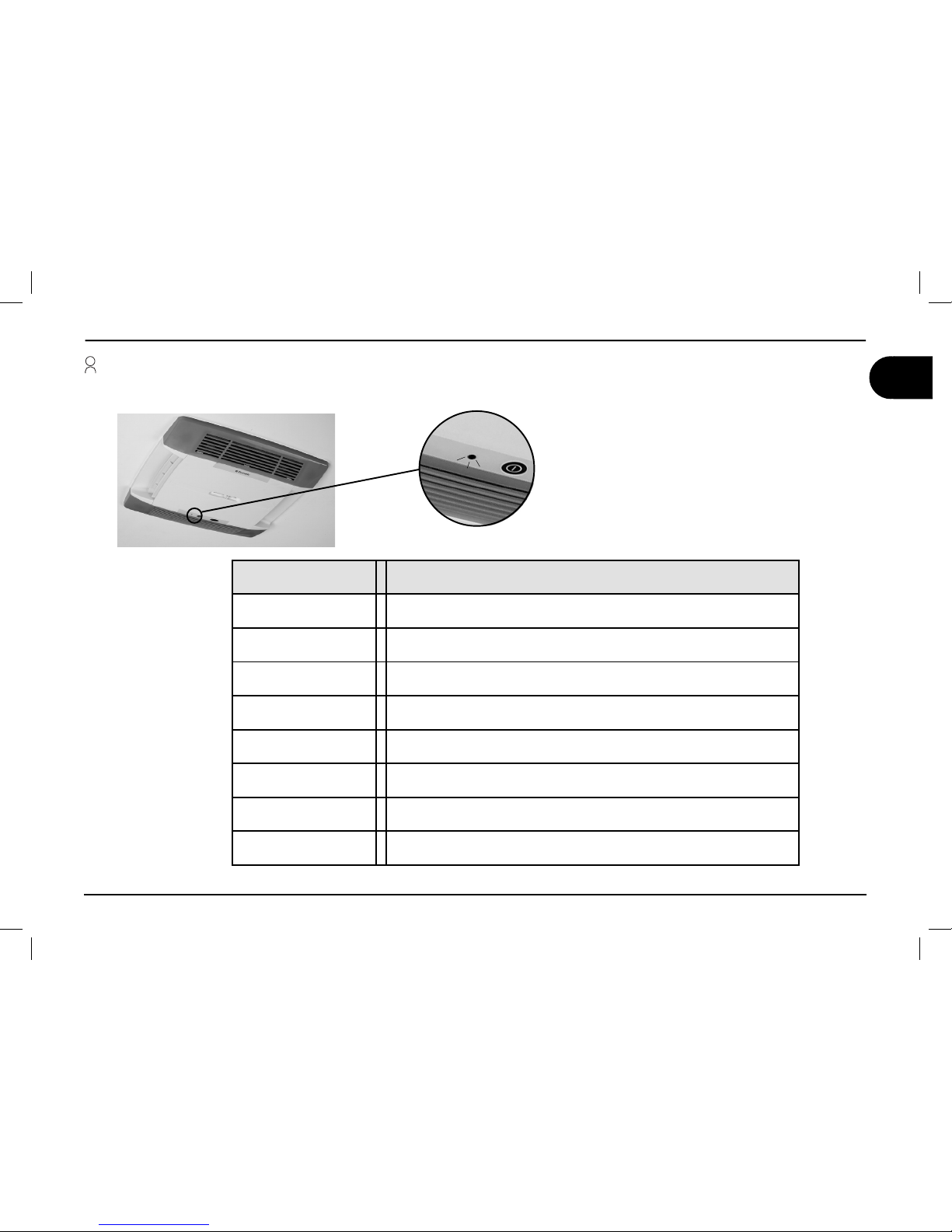
LED
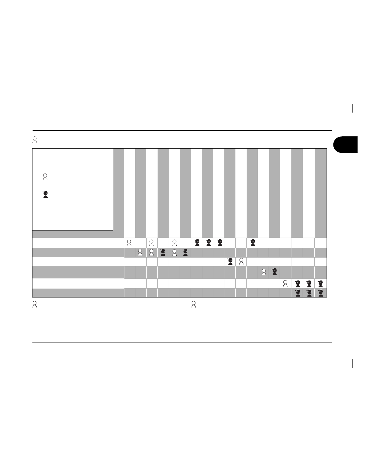
1.5.Description of the led state on the airdiffuser (B1600PLUS - B2200 - B2600)
LED State Description
Off Airconditioner off
Orange
Airconditioner on StandBy (switch ON - aiconditioner is waiting for
a command)
Green Airconditioner is running
Red (fi xed)
Anomaly - 230V power supply missing (12V
is present)
Red (1 fl ick) Anomaly - Malfunctioning of the E1 temperature probe (internal)
Red (2 fl icks) Anomaly - Malfunctioning of the E2 temperature probe (external)
Red (3 fl icks) Anomaly - Malfunctioning of the E3 temperature probe (external)
Flashing green Defrost / Start heat pump (B2600 only)
Page 16
14
users ‘ instructions
GB
B1600 - B1600PLUS - B2200 - B2600
1 general informations
* according to EN 14511
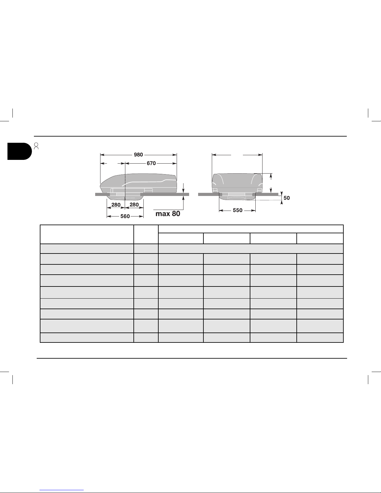
1.6. Technical data
Description Unit
Model
B1600 B1600 PLUS B2200 B2600
Refrigerant gas (type/quantity) see data plate
Refrigerating yield W
1500* 1500* 2050* 2500*
Cooling-Heating consumption W
620-800 620-800 950-1200 1200-1350
Heating capacity W
800 800 1200 3300
Electrical rating V-Hz
230-50 230-50 230-50 230-50
Protection degree IP
X4 X4 X4 X4
Conditioned air volume m3/h
310 310 380 380
Max internal volume of the vehicle
(insulated walls)
m
3
20 20 25 30
Weight Kg
30 30 34 40.5
235
650
310
min 30
Page 17
users ‘ instructions
15
GB
B1600 - B1600PLUS - B2200 - B2600
general informations 1
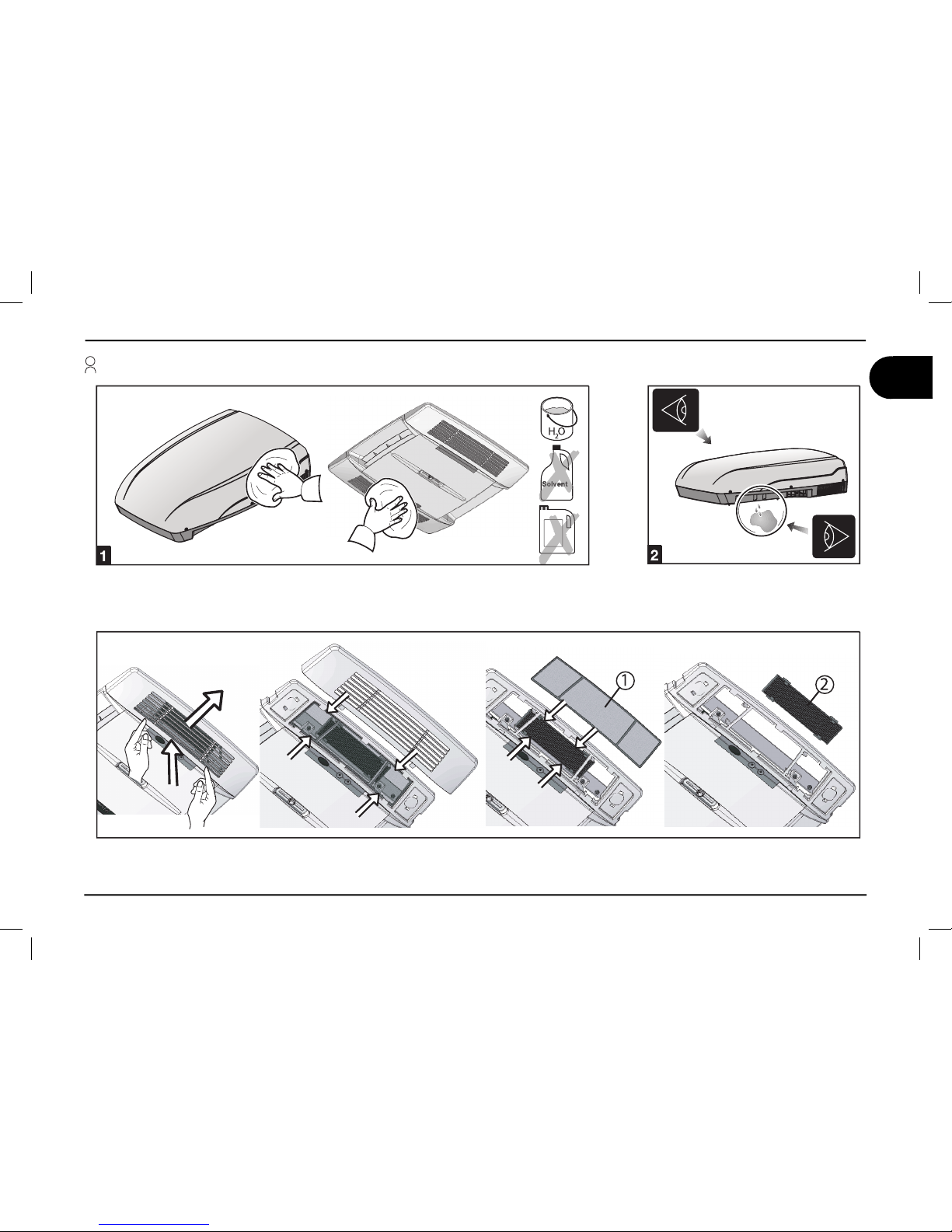
1.7. Ordinary maintenance
Cleaning; periodically clean the air conditioner and remove dust with a dump cloth. When
necessary, use a mild detergent. Do not use petrol or solvents.
Checks; regularly check the air conditioner and make sure that the water
outlet holes are not clogged.
Filters cleaning (1): periodically carry out this operation; wash the fi lters with a detergent solution and allow to dry before refi tting.
Active carbon fi lter (2): It’s recomended to change the active carbon fi lters every year.
Petrol
Page 18
16
users ‘ instructions
GB
B1600 - B1600PLUS - B2200 - B2600
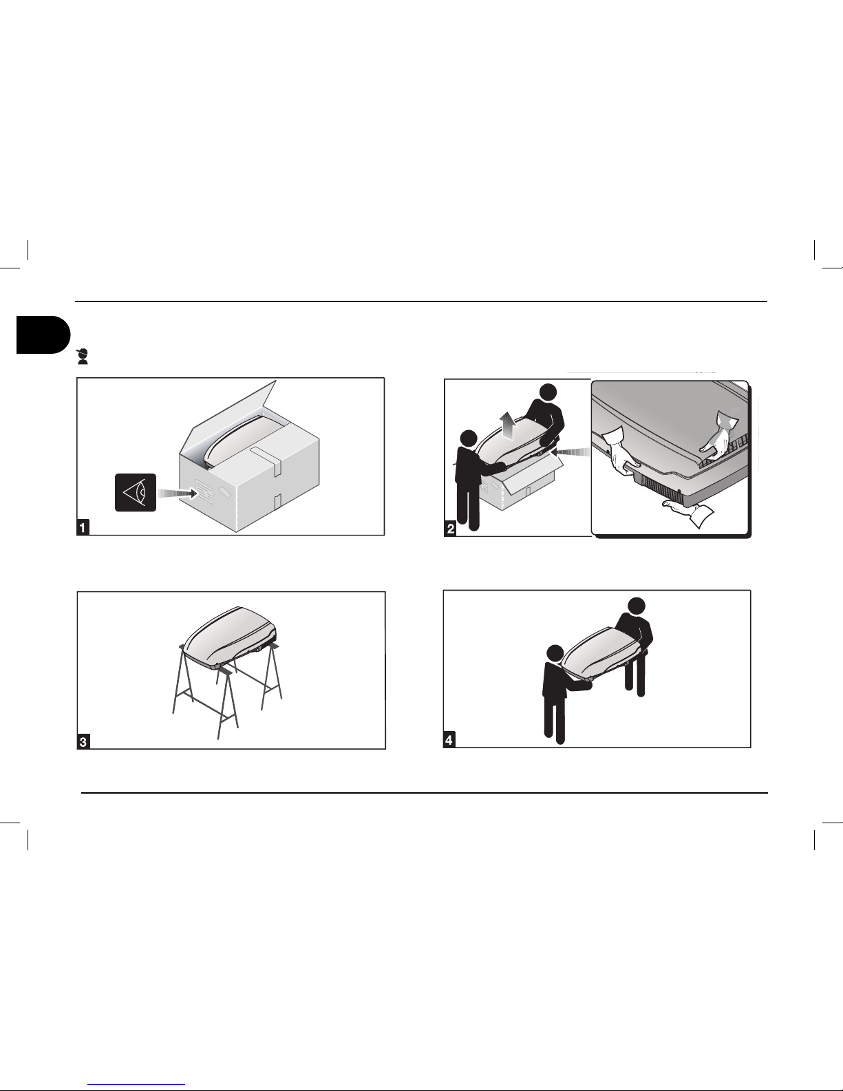
The air conditioner must be installed by skilled technicians. In addition to this requirement, the people making the unit installation must make sure
that the working conditions are safe for everybody concerned.
2.1. Packaging, unpacking and handling
Always follow the instructions printed on the packaging.
Remove the air conditioner from its packaging and made sure that
it is not damaged.
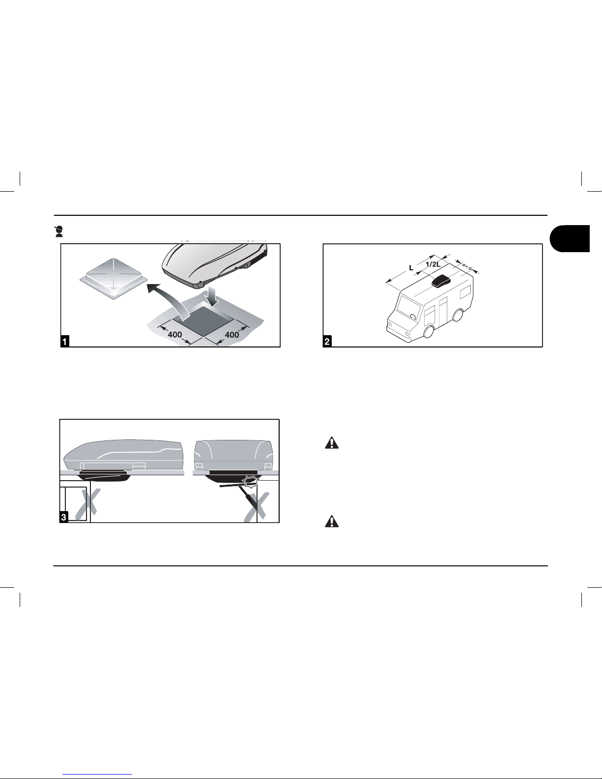
Never use the rear air openings to lift the air conditioner
from its packaging
Move the air conditioner to the installation site under safe conditions.
2 Installation instructions
Page 19
users ‘ instructions
17
GB
B1600 - B1600PLUS - B2200 - B2600
Installation instructions 2
To install the air conditioner, the roof shall have an opening of suitable sizes. It is possible to use an existing air inlet or make a new
one.
According to the vehicle dimensions and depending on the air
conditioning needs, one or more units can be installed. The air
conditioner must be installed right in the middle with respect to the
vehicle Width and length.
Before installing the unit, make sure that the opening does not
interfere with the existing furnishing (lamps, wardrobes, doors,
curtains, etc.). This check allows for an easy mounting of the air
conditioner and a troublefree air circulation.
contact the vehicle manufacturer and make sure that the
roof structure can tolerate the static load and the stress transmitted vehicle, especially under running conditions. Sometimes vehicle manufacturers previously arrange areas for the
unit installation weakening and/or electric cable from being
cut.
The air conditioner should preferably be installed on a
level plane. Maximum allowed inclination: 10°.
2.2. Preparing the roof opening
Page 20
18
users ‘ instructions
GB
B1600 - B1600PLUS - B2200 - B2600
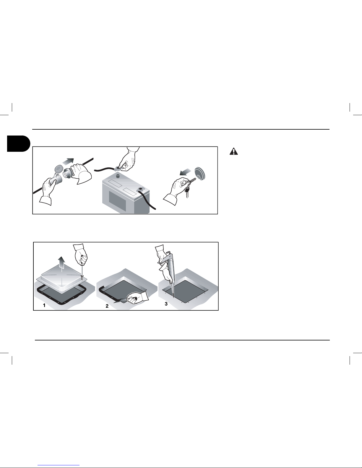
Danger of electrical hazards.
Turn all power sources off
Using an existing opening
Remove the skylight cover.
Clean the installation opening all around
by removing any adhesive residues.
Fill any existing screw hole or deformation
with fi ller or silicone.
1.
2.
3.
2 Installation instructions
Page 21
users ‘ instructions
19
GB
B1600 - B1600PLUS - B2200 - B2600
Installation instructions 2
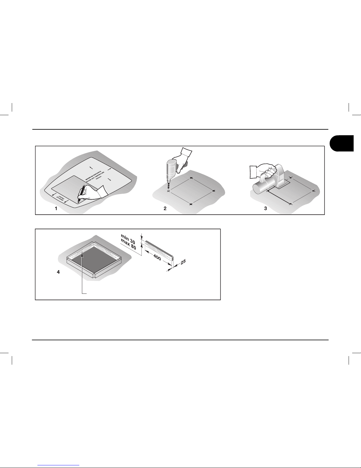
New installation opening
Using the printed cardboard template supplied with the unit, fi nd the position and di-
mensions of the new opening.
Drill the four corners.
Cut by joining the previously made holes.
If necessary, mount a reinforcing wooden
frame.
1.
2.
3.
4.
Drill a hole for the
supply cables
Page 22
20
users ‘ instructions
GB
B1600 - B1600PLUS - B2200 - B2600
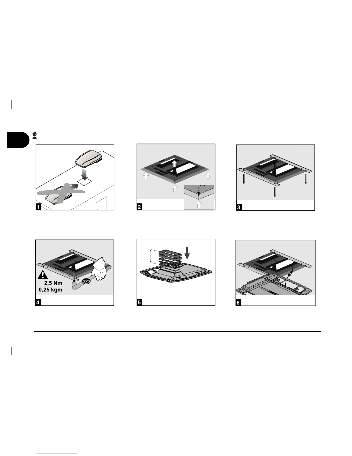
2.3. Mounting the air conditioner
Set the air conditioner onto the roof opening. Never slide the air conditioner on
the roof, but lift when moving it.
Note: the conical pins under the base
must enter the roof openings.
Fix the air diffuser brackets to the base
using the 4 screws provided.
Always tighten to the recommended torque wrench setting. Do not overtighten!
Mount the airdiffuser linking gaskets.
For correct thickness follow the table on
page 19.
Do the electrical connection as described
in paragraph 2.4.
2 Installation instructions
Page 23
users ‘ instructions
21
GB
B1600 - B1600PLUS - B2200 - B2600
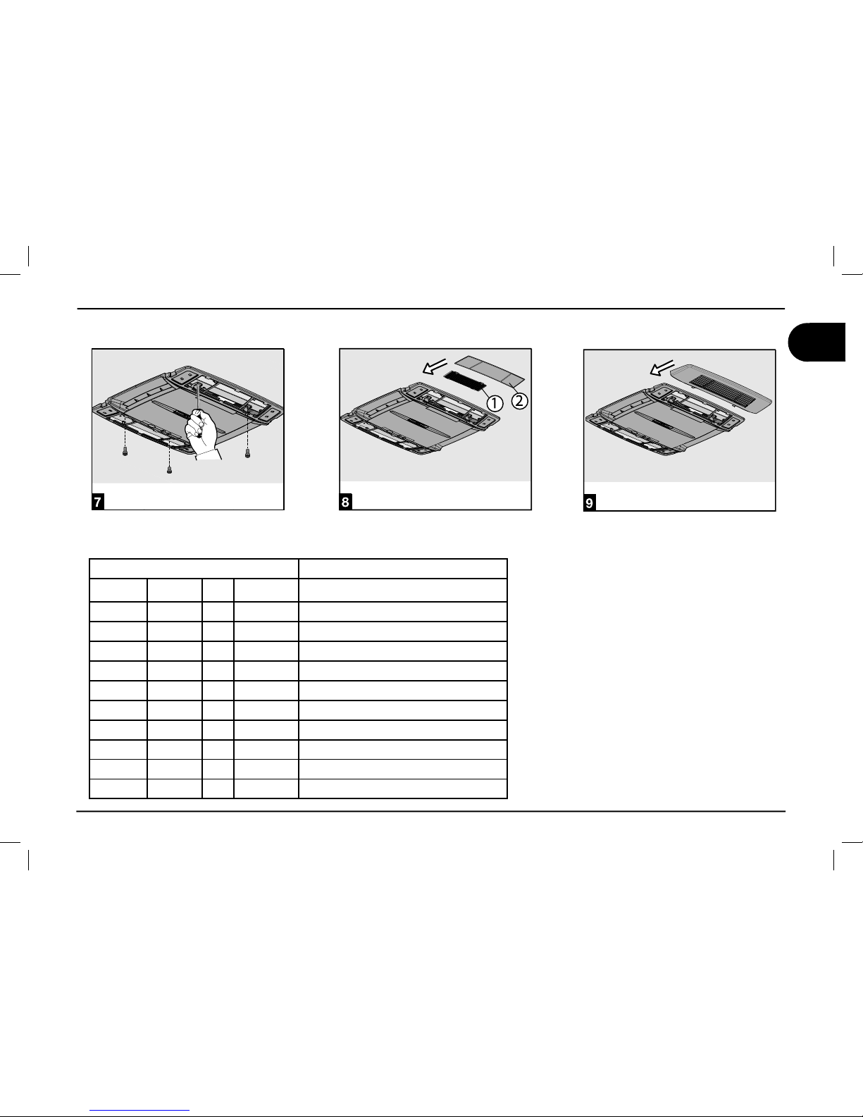
Installation instructions 2
Fix the cooling unit to the brackets using
the 4 screws provided.
Mount the fi lters in the order shown in
fi gure.
Mount the fi lters covers.
THICKNESS OF THE ROOF THICKNESS OF THE GASKET
= 30 mm 10 mm
from 30 to 35 mm 15 mm
from 35 to 40 mm 20 mm
from 40 to 45 mm 25 mm
from 45 to 50 mm 30 mm
from 50 to 55 mm 35 mm
from 55 to 60 mm 40 mm
from 60 to 65 mm 45 mm
from 65 to 70 mm 50 mm
from 70 to 75 mm 55 mm
from 75 to 80 mm 60 mm
Page 24
22
users ‘ instructions
GB
B1600 - B1600PLUS - B2200 - B2600
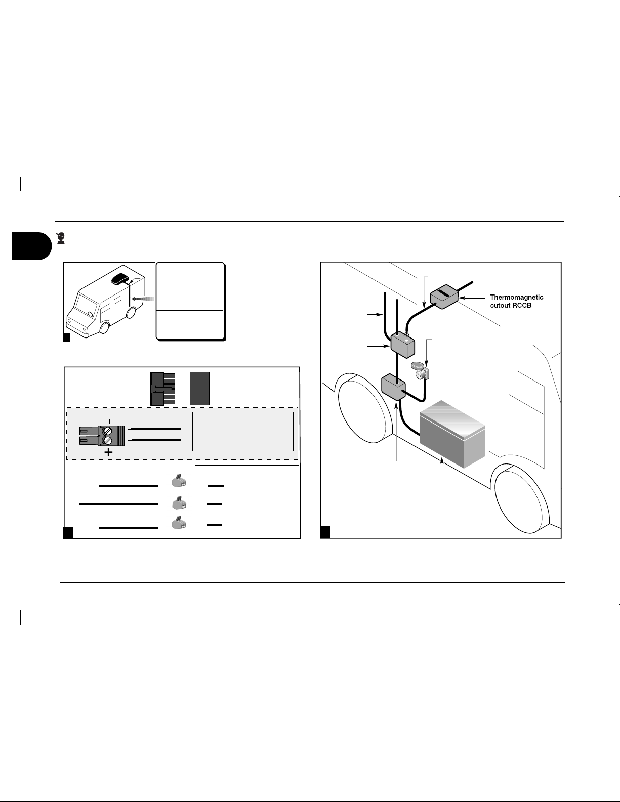
2.4. Electric connection
For the electric connections, always follow the national and local regulations
Arrange a specifi c electric system
Connect the wires to the air conditioner. Connect the electric system to a circuit supplying the required power
(see technical data) and fi tted with a good ground system.
B2200
REWOPCIRTCEL%
R
OTARENEG
HCTIWSREVOçEGNAH#
ROTARENEGSNIAM
SNIAMYLPPU3
SUOIRA
6
SRESU
ESU
&
XOB
YLP
PUSREWOPRENOITIDNOCRI!
HTG
NE,
M
NOITCESçSSOR#
M
M
,
QPMFDPOOFDUPS
GSPNBJSDPOEJUJPOFS
CBTF
QPMFDPOOFDUPSPO
UIFFMFDUSPOJDEFWJDF
JOTJEFBJSEJõVTFS
12V DC
#SPXOXJSF
#SPXOXJSF
230V 50Hz
10-&#"55&3:
10-&#"55&3:
$ZBOXJSF
$ZBOXJSF
(SFFO:FMMPXXJSF
(SFFO:FMMPXXJSF
2 Installation instructions
Page 25
users ‘ instructions
23
GB
B1600 - B1600PLUS - B2200 - B2600
SOLUTION
temperature less than 18°C
temperature over 40°C
check the set point temperature
defective thermal protection
switch wrongly positioned
defective heating resistance
refrigerant gas is not enough
damaged compressor
thermal exchange batteries are dirty
defective internal fan
air fi lter is clogged
defective external fan
water outlet holes are clogged
damaged sealing gasket
no power supply
low power supply (less than 200V)
defective capacitor
defective thermal protection
CAUSA
the air conditioner does not cool suffi ciently
the air conditioner does not heat enough
no air circulation into the vehicle
water leaks into the vehicle
the air conditioner does not start
the air conditioner stops running
Operations to be carried
out by the user
Operations to be carried out
by authorised personnel
3.1. Troubles, causes, solutions
3.2. Extraordinary maintenance
For the best performance of your air conditioner, have your dealer/workshop clean it thoroughly before use:
thermal exchange batteries
water outlet holes are properly cleaned.
1.
2.
3.3. Recycling
Regarding disposal and recycling, follow the national or local
regulations. To this end, address to the authorised environment
bodies.
Troubleshooting, maintenance, recycling 3
Page 26
24
GB
B1600 - B1600PLUS - B2200 - B2600
36
35
16
13
19
22
2
51
31
25
33
34
6
27
26
3
1
5
18
17
12
20
14
15
46
50
49
38
43
44
37
41
47
48
45
4
52
53
39
B2200
B1600 PLUS
46
50
49
38
42
40
37
41
47
48
45
4
52
53
39
B1600
54
55
56
57
58
59
9
8
11
7
10
32
42
40
30
29
23
24
28
21
60
61
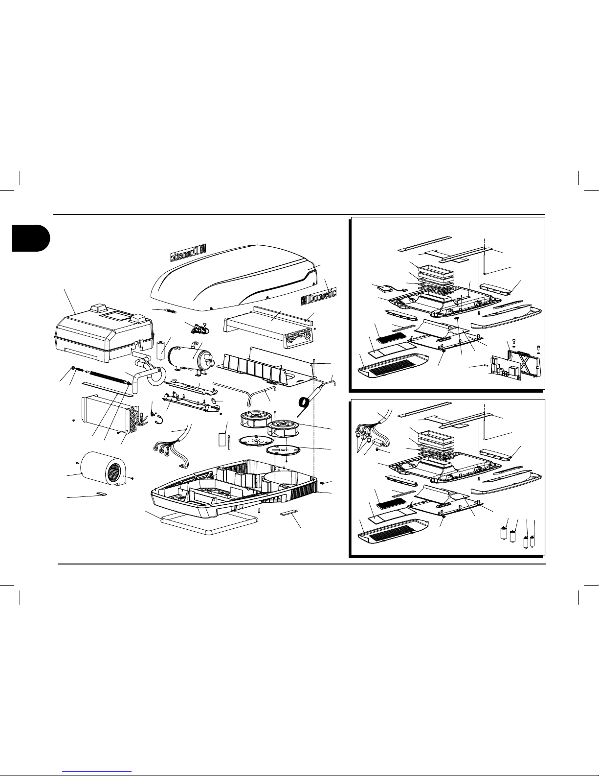
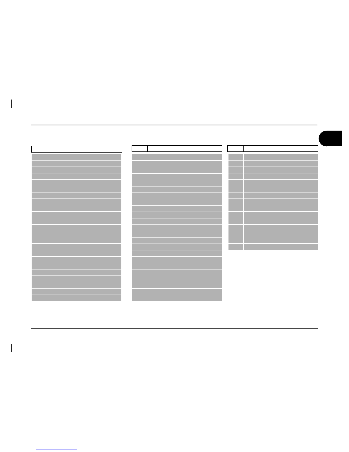
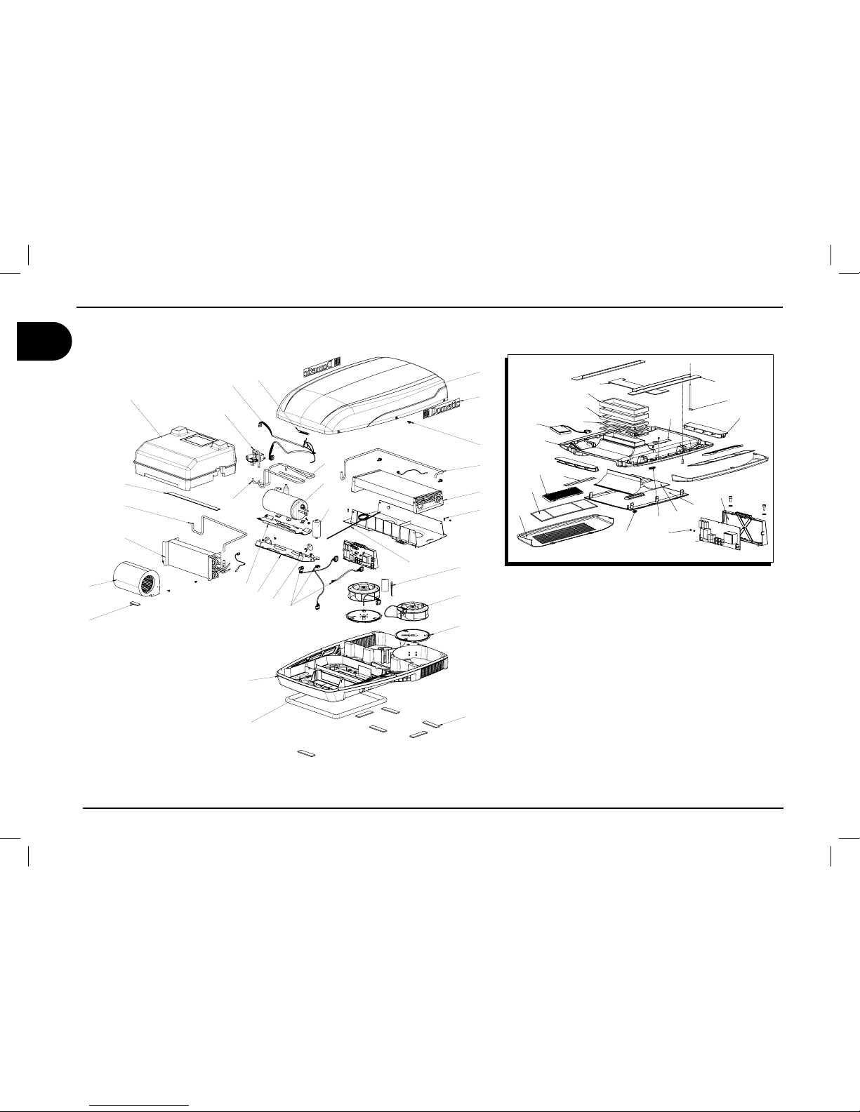
Spare part list B1600 - B1600 PLUS - B2200
Page 27
25
GB
B1600 - B1600PLUS - B2200 - B2600
N. DESCRPTION
1 PAN BASE
2 COVER
3 RIVETS TWO STAGE
4 INSULATOR
5 GASKET
6 INSERTS
7 SUPPORT
8 SUPPORT
9 COMPRESSOR
10 CAPACITOR
11 VIBRATION DAMPER
12 COMPRESSOR WIRING
13 EVAPORATOR
14 GASKET
15 FAN
16* RESISTOR
17* BUSHING
18* SPRING
19 THERMAL SWITCH
20 OR GASKET
21 RIVETS
22 LABEL
23 CAPACITOR
24 CAPACITOR
25 PLENUM
26 FAN SUPPORT
27 FAN
28 RELAY BOARD
29 CAPACITOR
30 CAPACITOR
31 CONDENSER
32 PIPE
33 PIPE
34 FILTER KIT
35 GASKET
36 HEAT INSULATOR BOX
37 AIR DIFFUSER BASE
38 AIR DIFFUSING FLAP
39 GRILLE
40 DEFLECTOR SLIDE
41 KNOB
42 COVER
43 RECEIVER BOARD
44 RECEIVER COVER
45 LABEL
46 FIXING BRACKET
47 GASKET
48 GASKET
49 GASKET
50 SCREW
51 LABEL
52 ACTIV CARBON FILTER
53 FILTER
54 WIRING
55 WIRING
56 SWITCH
57 THERMOSTAT
58 KNOB
59 GASKET
60 SUPPORT
61** LED BOARD
N. DESCRPTION N. DESCRPTION
* (only for models equipped with resistance) - **(only for models equipped with light)
Spare part list B1600 - B1600 PLUS - B2200
Page 28
26
GB
B1600 - B1600PLUS - B2200 - B2600
14
15
20
1
3
19
47
48
49
4
37
30
29
39
45
41
44
40
42
23
38
50
43
46
21
28
51
2
22
12
36
9
10
32
35
13
24
8
11
7
6
33
31
34
27
26
5
25
16
17
18
B2600
Spare part list B2600
Page 29
27
GB
B1600 - B1600PLUS - B2200 - B2600
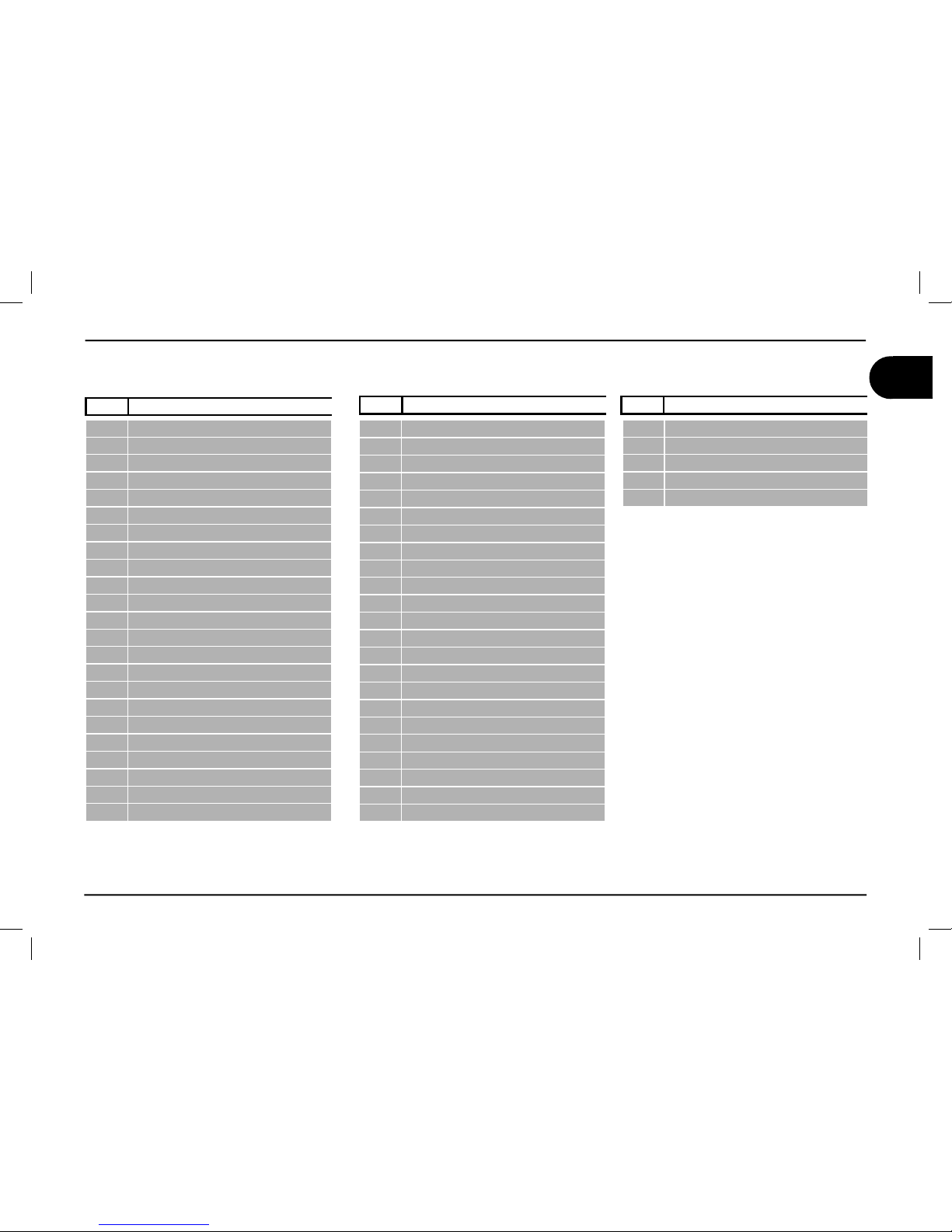
N. DESCRPTION
1 PAN BASE
2 COVER
3 RIVETS TWO STAGE
4 INSULATOR
5 GASKET
6 INSERTS
7 SUPPORT
8 SUPPORT
9 COMPRESSOR
10 CAPACITOR
11 VIBRATION DAMPER
12 COMPRESSOR WIRING
13 EVAPORATOR
14 GASKET
15 FAN
16 SOLENOID VALVE
17 RETURN PIPE
18 DELIVERY PIPE
19 LED BOARD
20 OR GASKET
21 RIVETS
22 LABEL
23 SUPPORT
24 WIRING
25 PLENUM
26 FAN SUPPORT
27 FAN
28 RELAY BOARD
29 FILTER
30 ACTIV CARBON FILTER
31 CONDENSER
32 PIPE
33 PIPE
34 CAPILLARY TUBE
35 GASKET
36 HEAT INSULATOR BOX
37 AIR DIFFUSER BASE
38 AIR DIFFUSING FLAP
39 GRILLE
40 DEFLECTOR SLIDE
41 KNOB
42 COVER
43 RECEIVER BOARD
44 RECEIVER COVER
45 LABEL
46 FIXING BRACKET
47 GASKET
48 GASKET
49 GASKET
50 SCREW
51 LABEL
N. DESCRPTION N. DESCRPTION
Spare part list B2600
Page 30
28
users ‘ instructions
GB
B1600 - B1600PLUS - B2200 - B2600
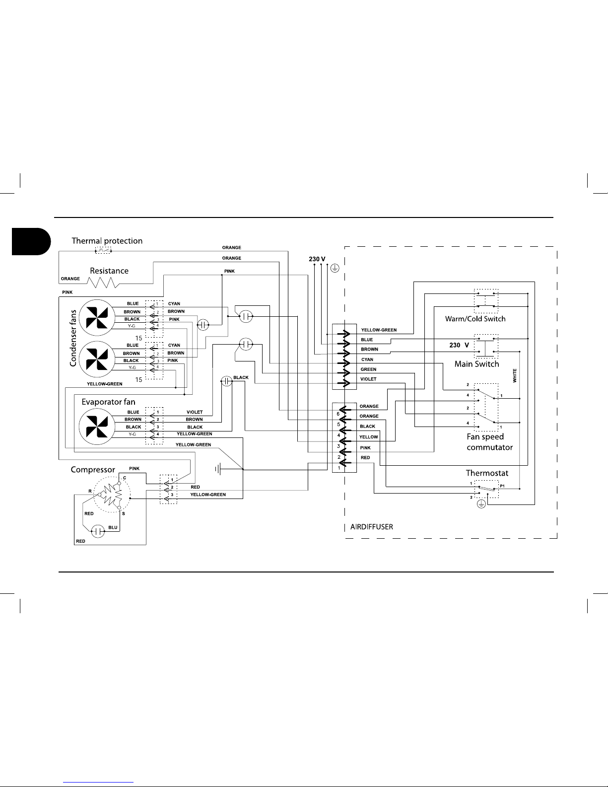
WIRING DIAGRAM B1600
(Rev. 04)
V'
V'
V'
V'
V'
1
2
3
4
5
6
Page 31

users ‘ instructions
29
GB
B1600 - B1600PLUS - B2200 - B2600
WIRING DIAGRAM B1600 PLUS / B2200
NWORB
EUL
B
N
EERG-WOLLEY
CA
V032
LARTUEN - 2T
*
ENIL - 1
T
*
123
DNUORG - 3T
*
1
2
1
2
D
ER
NEERG
NAYC
WOLL
E
Y
NWORB
E
TIH
W
CKAL
B
EUL
B
YARG
TE
LOIV
RED
GREEN
CYAN
YELLOW
BROWN
WHITE
BLAK
BLUE
GRAY
VIOLET
8J
xJ
4C4C
1
2
3
4
5
6
7
8
9
01
3C3C
1234567891011
12
xJ
xC
1
2
Led
board
xJ
xC
1
2
Led
board
xJ
xC
1
2
Led
board
xJ
xC
1
2
Led
board
AIR DIFFUSER
*
* *
* *
* *
*
ROTSISE
R
T
AEH ROTSISE
R
T
AEH
H
C
T
I
WS O
M
RET H
C
T
I
WS O
M
RET
ORANGE
0/0''
0/0''
&$0/0.:
&$0/0.:
*/7&35&3
*/7&35&3
+
+
+
+
+
+
OPTIONAL CONNECTION
TO SWITCH ON THE AIR
DIFFUSER LIGHT ALSO
WHEN THERE IS NO MAIN.
PLEASE USE THE
PROVIDED CONNECTOR
PLUGGED IN THE BOARD
EUL
B
N
E
E
RG-WO
L
L
E
Y
D
E
R
KN
I
P
HCTI
W
S
OM
RE
T
HCTI
W
S
OM
RE
T
*
2F2F
*
123
*
4F4F
*
2
x
O 2xO
*
*
5F5F
*
F
u
xx Fuxx
1xO1
xO
*
1F1F
*
*
3F3F
**
*
*
1
2
3
4
COMPRESSOR
N
EERG-W
O
LLE
Y
N
EE
R
G-W
O
L
L
E
Y
K
C
A
L
B
NW
O
RB
EU
LB
1
2
3
4
FAN2 CONDERNSER
N
EE
R
G-W
O
L
L
E
Y
K
C
A
L
B
NW
O
RB
EU
LB
123
4
FAN1 CONDERNSER
KCALB
NWO
R
B
EUL
B
FAN EVAPORATOR
+ 12vdc BATTERY
- BATTERY
TEMPERATURE
PROBE
BATTERY
FUSE F2AL250V
MAIN FUSE F10AL250V
."*/'64&
."*/'64&
#"55&3:'64&
#"55&3:'64&
5&.1130#&
5&.1130#&
"694&3*"-
"694&3*"-
#"55&3:
#"55&3:
$0/%'"/
$0/%'"/
$0/%'"/
$0/%'"/
&7"1'"/
&7"1'"/
3&4*4503
3&4*4503
."*/
."*/
3&4*4503
3&4*4503
$0.13&4403
$0.13&4403
3&.05&
3&.05&
+
+
3
3
3
3
5
5
53
53
+
+
$
$
$
$
$
$
$
$
$
$
$
$
$
$
$
$
$
$
$
$
+
+
+
+
+
+
+
+
+
+
+
+
2
2
3M
3M
3M
3M
3M
3M
3M
3M
3M
3M
6
6
3
3
6
6
$
$
$
$
%;
%;
+
+
+"
+"
+#
+#
$
$
$
$
')
')
'
'
'
'
')
')
Page 32

30
users ‘ instructions
GB
B1600 - B1600PLUS - B2200 - B2600
WIRING DIAGRAM B2600
NWORB
EUL
B
N
EERG-WOLLEY
CA
V032
LARTUEN - 2T
*
ENIL - 1
T
*
123
DNUORG - 3T
*
121
2
D
ER
NEERG
NAYC
WOLL
E
Y
NWORB
E
TIH
W
CKAL
B
EULB
YARG
TE
LOIV
RED
GREEN
CYAN
YELLOW
BROWN
WHITE
BLAK
BLUE
GRAY
VIOLET
xJ
1
2
3
4
5
6
7
8
9
01
3C3C
1234567891011
12
xJ
xC
1
2
Led
board
xJ
xC
1
2
Led
board
xJ
xC
1
2
Led
board
xJ
xC
1
2
Led
board
AIR DIFFUSER
VALVE
ORANGE
0/0''
0/0''
&$0/0.:
&$0/0.:
*/7&35&3
*/7&35&3
OPTIONAL CONNECTION
TO SWITCH ON THE AIR
DIFFUSER LIGHT ALSO
WHEN THERE IS NO MAIN.
PLEASE USE THE
PROVIDED CONNECTOR
PLUGGED IN THE BOARD
EUL
B
N
EERG-WOLLEY
D
E
R
KN
I
P
HCTI
W
S
OM
RE
T
HCTI
W
S
OM
RE
T
*
2F2F
*
123
*
4F4F
*
2
x
O 2xO
*
*
5F5F
*
F
u
xx Fuxx
1xO1
xO
*
1F1F
*
*
3F3F
**
*
*
1
2
3
4
COMPRESSOR
N
EERG-W
O
LLE
Y
N
EE
R
G-W
O
L
L
E
Y
K
C
A
L
B
NW
O
RB
EU
LB
1
2
3
4
FAN2 CONDERNSER
N
EE
R
G-W
O
L
L
E
Y
K
C
A
L
B
NW
O
RB
EU
LB
123
4
FAN1 CONDERNSER
KCALB
NWO
R
B
EUL
B
FAN EVAPORATOR
+ 12vdc BATTERY
- BATTERY
TEMPERATURE
PROBE
BATTERY
FUSE F2AL250V
MAIN FUSE F10AL250V
."*/'64&
."*/'64&
#"55&3:'64&
#"55&3:'64&
&7"1130#&
&7"1130#&
$0/%130#&
$0/%130#&
#"55&3:
#"55&3:
"694&3*"-
"694&3*"-
$0/%'"/
$0/%'"/
$0/%'"/
$0/%'"/
&7"1'"/
&7"1'"/
)00%
)00%
."*/
."*/
$0.13&4403
$0.13&4403
7"-7&
7"-7&
3&.05&
3&.05&
3&.05&
3&.05&
+
+
Page 33

©DOMETIC - 2009 Tutti i diritti riservati - Stampato in Italia -
Nessuna parte di questo manuale può essere riprodotta, copiata o divulgata
con qualsiasi mezzo senza l’autorizzazione scritta di DOMETIC
Le fi gure, Ie descrizioni, i riferimenti ed i dati tecnici contenuti nel presente
manuale sono indicativi e non impegnativi.
DOMETIC si riserva il diritto di apportare in qualsiasi momento e senza
preavviso Tutte le modifi che che riterrà opportuno, nella costante ricerca di
migliorare Ia qualità E Ia sicurezza, senza impegnarsi ad aggiornare di volta
in volta questo manuale.
Conservare questo documento per futuri riferimenti.
Validità di garanzia
“Il Prodotto è garantito secondo Legge e norme emanate a seguito del recepimento della Direttiva 1999/44/CE.”
La garanzia del produttore viene espressamente esclusa nel caso la rottura e/o l’anomalo funzionamento del
Prodotto sia causa e/o dipendenza di un errato montaggio.
E’ in facoltà del Consumatore provvedere al montaggio del Prodotto tramite i vari rivenditori autorizzati ma non
dipendenti da Dometic.
Page 34

Norme per la sicurezza sull’impatto ambientale e per il corretto smaltimento
Ogni organizzazione ha il compito di applicare delle procedure per individuare, valutare e controllare l’infl uenza che le proprie attività (produzione,
prodotti, servizi, ecc.) hanno sull’ambiente.
Le procedure da seguire per identifi care impatti ambientali signifi cativi sull’ambiente devono tener conto dei seguenti fattori:
- Uso delle materie prime e delle risorse naturali
- emissioni in atmosfera
- scarichi dei liquidi
- gestione dei rifi uti e riciclaggio
- contaminazione del suolo
Allo scopo di minimizzare l’impatto ambientale il costruttore fornisce di seguito alcune indicazioni, queste dovranno essere considerate e rispettate
da tutti coloro che, a qualunque titolo, interagiscono con l’apparecchiatura nell’arco della sua vita prevista.
- tutti i componenti di imballo vanno smaltiti (possibilmente riciclati) secondo le leggi nazionali del paese in cui lo smaltimento viene effettuato
- tutti i componenti dei prodotti devono essere smaltiti (possibilmente riciclati) secondo le leggi nazionali del paese in cui lo smaltimento viene
effettuato
- per un corretto smaltimento l’apparecchiatura dovrebbe essere trasferita ad una ditta di smaltimento rifi uti autorizzata allo scopo di assicurare il
riuso dei componenti riciclabili ed un adeguato smaltimento dei componenti restanti
- durante la fase di installazione fare in modo che l’ambiente abbia un adeguato ricambio d’aria per evitare la concentrazione di aria insalubre per
gli operatori
- in fase di uso e manutenzione evitare di disperdere nell’ambiente prodotti inquinanti
(oli, grassi, ecc)
- mantenere la rumorosità ai livelli minimi per ridurre l’inquinamento acustico
Per ulteriori indicazioni sul corretto disassemblaggio dei nostri prodotti puoi fare riferimento ai manuali di riciclaggio su www.dometic.com/ambien-
te.........
Page 35

1 Informazioni generali
1.1. Scopo del manuale.............................................4
1.2. Identifi cazione costruttore e condizionatore.......4
1.3. Descrizione del condizionatore...........................4
1.4. Consigli per l’uso................................................8
1.5. Descrizione dei comandi................................... 9
1.6. Dati tecnici......................................................... 14
1.7. Manutenzione ordinaria....................................15
2 Informazioni per l’installazione
2.1. Imballo, disimballo e movimentazione..............16
2.2. Preparazione apertura sul tetto........................17
2.3. Montaggio del condizionatore...........................20
2.4. Collegamento elettrico......................................22
3 Ricerca guasti, manutenzione, riciclaggio
3.1. Inconvenienti, cause, rimedi.............................23
3.2. Manutenzione straordinaria..............................23
3.3. Messa fuori servizio e riciclaggio......................23
Tavola catalogo ricambi ...................................24
Schemi elettrici ...............................................28
Indice
Operation, Maintenance and
Installation manual
Air conditioner
GB
I
D
F
Handleiding voor bediening,
onderhoud en installatie
Airconditioner
NL
Manual de instrucciones para el uso, la manutención
y la instalación
Acondicionator
E
Livrete de instruções para uso, manutenção
e instalação
Aparelho de ar condicionado
P
Handbok för drift, underhåll och
installation
Luftkonditionering
S
Käyttö-, huolto- ja
asennusohje
Ilmastointilaite
FIN
Brukerveiledning og manual
til vedlikehold og installasjon
Airconditioner
N
DK
Libretto istruzioni per l’uso, la manutenzione e
l’installazione
Condizionatore
Bedienungs- und
Wartungsanleitung
Klimaanlage
Mise en route, entretien et
installation
Climatiseur
Brugervejledning og manual
til vedligeholdelse og installation
Airconditioner
Page 36

B1600 - B1600PLUS - B2200 - B2600
4
Istruzioni d’uso per l’utilizzatore
I
1.1. Scopo del manuale
Questo manuale è stato redatto dal Costruttore ed è parte integrante del
corredo del condizionatore.
Le informazioni contenute, se rispettate, potranno garantire l’uso corretto
del condizionatore.
La prima parte del manuale è riservata agli utilizzatori
, mentre la seconda è riservata al personale esperto che esegue l’installazione del
condizionatore.
Per mettere in evidenza alcune parti del testo, sono stati inseriti i seguenti simboli:
L’operazione può comportare fonte di pericolo.
Suggerimenti utili.
Informazioni riguardo il rispetto dell’ambiente.
1.2. Identifi cazione costruttore e condizionatore
1.3. Descrizione del condizionatore
(B1600 B1600PLUS B2200)
II condizionatore è stato progettato e costruito per essere installato
su veicoli (camper, caravan, motor home ecc.) al fi ne di migliorare la
temperatura interna. Nei periodi caldi fornisce aria fresca e deumidifi cata, nei periodi freddi fornisce aria calda senza tuttavia sostituire il
riscaldamento in dotazione al veicolo. In entrambi i casi la temperatura
dell’aria è regolabile.
Aria fresca - Descrizione del funzionamento
II sistema è composto da: compressore (a), condensatore (b), evaporatore (d) e liquido refrigerante in pressione.
II liquido refrigerante cambiando stato fi sico, da liquido a gassoso,
riscalda o raffredda i componenti in cui transita.
L’evaporatore reso freddo viene attraversato dall’aria interna spinta
dal ventilatore (c).
La stessa ne esce raffreddata e deumidifi cata. Questa azione prolungata
nel tempo crea una riduzione della temperatura all’interno del mezzo.
Aria calda - Descrizione del funzionamento
L’aria ambiente passando attraverso la resistenza elettrica (e), per mezzo
del ventilatore (c), viene riscaldata e reimmessa nell’ambiente.
1 Informazioni generali
Identifi cazione
del costruttore
Marcature di conformità
Modello/Numero di matricola
Anno di costruzione
Dati tecnici
Page 37

Istruzioni d’uso per l’utilizzatore
5
B1600 - B1600PLUS - B2200 - B2600
Informazioni generali 1
I
Compressore (a)
Condensatore (b)
Evaporatore (d)
Resistenza (e)
scarico condensa
Ventilatore (c)
Flusso d’aria immessa dall’esterno
Flusso d’aria immessa dall’esterno
aria calda
espulsa
aria trattata
reimmessa
nell’abitacolo
Flusso d’aria immessa dall’esterno
aria calda
espulsa
fl usso d’aria
prelevata
dall’abitacolo
Page 38

B1600 - B1600PLUS - B2200 - B2600
6
Istruzioni d’uso per l’utilizzatore
I
1 Informazioni generali
Descrizione del condizionatore (B2600)
II condizionatore è stato progettato e costruito per essere installato su
veicoli (camper, caravan, motor home ecc.) al fi ne di migliorare la tem-
peratura interna. Nei periodi caldi fornisce aria fresca e deumidifi cata,
nei periodi freddi fornisce aria calda senza tuttavia sostituire il riscaldamento in dotazione al veicolo. In entrambi i casi la temperatura dell’aria
è regolabile.
Aria fresca - Descrizione del funzionamento
II sistema è composto da: compressore (a), condensatore (b), evaporatore
(d) e liquido refrigerante in pressione.
II liquido refrigerante cambiando stato fi sico, da liquido a gassoso, riscalda
o raffredda i componenti in cui transita.
L’evaporatore reso freddo viene attraversato dall’aria interna spinta dal
ventilatore (c).
La stessa ne esce raffreddata e deumidifi cata. Questa azione prolungata
nel tempo crea una riduzione della temperatura all’interno del mezzo.
Aria calda - Descrizione del funzionamento
Per mezzo di una elettrovalvola (f) è possibile invertire il ciclo del gas
refi gerante. Il calore accumulato dal gas refi gerante viene smaltito dalla
batteria interna introducendo calore nell’abitacolo per mezzo del ventilatore (c). Questa azione prolungata nel tempo crea un aumento della
temperatura all’interno del mezzo.
Page 39

Istruzioni d’uso per l’utilizzatore
7
B1600 - B1600PLUS - B2200 - B2600
Informazioni generali 1
I
Compressore (a)
Condensatore (b)
Evaporatore (d)
Elettrovalvola (f)
scarico condensa
Ventilatore (c)
F
lusso d’aria immessa dall’esterno
Flusso d’aria immessa dall’esterno
aria calda
espulsa
aria trattata
reimmessa
nell’abitacolo
Flusso d’aria immessa dall’esterno
aria calda
espulsa
fl usso d’aria
prelevata
dall’abitacolo
Page 40

B1600 - B1600PLUS - B2200 - B2600
8
Istruzioni d’uso per l’utilizzatore
I
1.4. Consigli per l’uso
Le prestazioni del condizionatore possono essere migliorate adottan-
do alcuni accorgimenti.
Migliorare I’isolamento termico del veicolo eliminando le fessure e
coprendo le superfi ci in vetro con tende rifl ettenti.
Evitare l’apertura frequente di porte e fi nestre quando non neces-
sario.
Scegliere la temperatura e la velocità di ventilazione adeguata.
Orientare opportunamente i convogliatori del fl usso aria.
Al fi ne di evitare condizioni del malfunzionamento del condizionatore
e rischi per la persona, adottare le seguenti cautele:
Non ostruire con tessuti, carta o oggetti, l’entrata e l’uscita dell’aria
di ventilazione;
non introdurre nelle aperture mani o oggetti;
non spruzzare acqua all’interno del condizionatore;
non avvicinarsi al condizionatore con sostanze infi ammabili.
•
•
•
•
•
•
•
•
Regolazione e bilanciamento direzione del fl usso aria
Orientare i due defl ettori scegliendo la posizione desiderata. Per bilanciare il fl usso dell’aria è necessario ruotare il pomello centrale in senso
antiorario, scegliere la posizione desiderata e ruotare il pomello in senso orario.
1 Informazioni generali
Page 41

Istruzioni d’uso per l’utilizzatore
9
B1600 - B1600PLUS - B2200 - B2600
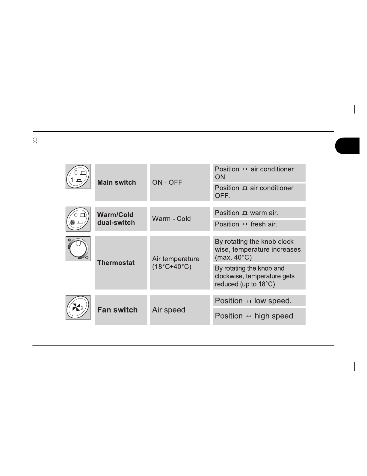
Informazioni generali 1
Interruttore
generale
Accensione Spegnimento
Posizione
si accende
il condizionatore.
Posizione si spegne il
condizionatore.
Commutatore Caldo - Freddo
Posizione si ottiene
aria calda.*
Posizione si ottiene
aria fresca.
Termostato
Temperatura aria
(18°C-40°C)
Ruotando in senso orario si alza la temperatura
dell’aria (max 40°C)
Ruotando in senso
antiorario si abbassa
la temperatura dell’aria
(fi no a 18°C)
Commutatore
ventola
Velocità aria
Posizione si ottiene la
velocità ridotta
Posizione si ottiene la
velocità massima.
I
Comandi manuali (B1600)
1.5.Descrizione dei comandi
* (solo per i modelli dotati di resistenza)
Page 42

B1600 - B1600PLUS - B2200 - B2600
10
Istruzioni d’uso per l’utilizzatore
I
1 Informazioni generali
1.5.Descrizione dei comandi
on/off
velocità
ventola
luce**
Modalità
selezione velocità
ventola
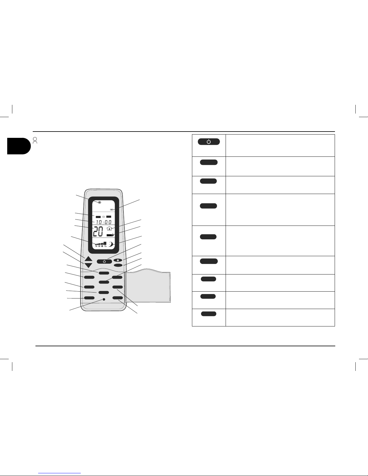
Telecomando (B2200 B1600PLUS B2600)
* (solo per i modelli dotati di resistenza) - ** (solo per i modelli dotati di luce)
ON/OFF
Premere il pulsante ON/OFF per accendere il
condizionatore. Quando è spento tutti i simboli sono
spenti tranne l’orologio e si possono utilizzare i
pulsanti ROOM e LIGHT**.
F°/C°
F°/C°
Scegliere l’unità di misura di temperatura tra Celsius (°C) or Fahrenheit (°F).
Questa funzione è abilitata se la temperatura è
visibile.
LIGHT
LIGHT
LIGHT**
Premere questo pulsante per accendere o spegnere
le luci del diffusore (se disponibili). Questo pulsante
funziona anche se il telecomando è spento.
ROOM
ROOM
Premere questo tasto per visualizzare la temperatura interna (simbolo “room”). Ripremere questo
pulsante per ritornare al set point. Questo pulsante
funziona anche se il telecomando è spento.
CLOCK
CLOCK
Premere questo tasto per più di 2 secondi per impostare l’orario (utilizzando i tasti + e - ). Premere il tasto
“SET” per confermare le modifiche. Dopo 15 secondi le modifiche sono confermate automaticamente.
SET
SET
Questo pulsante ha due funzioni:
1) Confermare il settaggio dell’orologio
2) Reinviare le impostazioni attuali del condizionatore
TIMER
TIMER
Premere questo pulsante per impostare l’ora di
accensione e/o spegnimento automatico.
SLEEP
SLEEP
Premendo questo pulsante si attiva la funzione
SLEEP. Il set point è regolato automaticamente per
aumentare il comfort durante il riposo.
I FEEL
I FEEL
Ogni 10 minuti il set point di funzionamento viene
adeguato alla temperatura rilevata dal telecomando.
Il pulsante “RESET” riporta tutti i parametri configurati a quelli di default.
+
-
MODE
¡$
CLOCK
TIMER
SET
SLEEP
I FEEL
ROOM
F°/C°
LIGHT
LIGHT
IFEEL
IFEEL
0/
0''
Simbolo pile
scariche
Orologio
Set Point
Orologio
F°/C°
Set
Room
Reset
Temperatura
della stanza
Mode
Su(+)
Giu(-)
Timer
Sleep
I Feel
Timer
Sleep
I Feel
Page 43

Istruzioni d’uso per l’utilizzatore
11
B1600 - B1600PLUS - B2200 - B2600
Informazioni generali 1
I
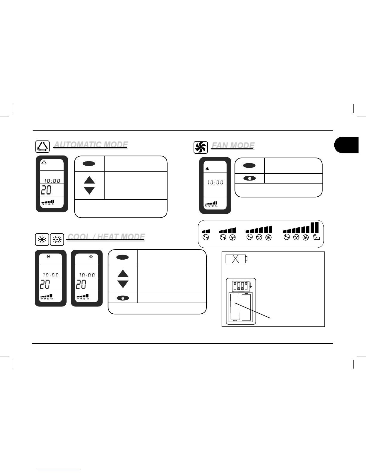
* (solo per i modelli dotati di resistenza) - ** (solo per i modelli dotati di luce)
MODALITA’ AUTOMATICA
¡$
AUTO
MODALITA’ FREDDO/ CALDO*
MODALITA’ VENTILAZIONE
¡$ ¡$
30%%$
30%%$
30%%$
30%%$
Velocità ventola disponibili (Freddo/Caldo/Ventilazione)
MODE
Premere il pulsante MODE
fino ad “AUTO”
+
-
Selezionare la temperatura
desiderata (Set Point)
(16°C - 31°C)
In questa modalità il pulsante ventola (fan) è
disattivato. Si possono utilizzare i tasti LIGHT**
e ROOM.
MODE
Premere il pulsante MODE.
Selezionare “FREDDO” o
“CALDO”*
+
-
Selezionare la temperatura
desiderata (Set Point)
(16°C - 31°C)
Selezionare la velocità della
ventola
Si possono utilizzare i tasti LIGHT** e ROOM.
MODE
Premere il pulsante
MODE. Selezionare
ventilazione.
Selezionare la velocità
della ventola
Pile scariche
Quando le pile del telecomando
sono scariche il simbolo appare
sul display.
Dopo ogni comando il simbolo
lampeggia per 2 secondi.
BATTERYCOMPARTMENT
ON BACK SIDE OF REMOTE
CONTROL
1
234
O
F
F
OFF
Sostituire le pile
2x1.5V AAA
Si possono utilizzare i tasti LIGHT** e
ROOM.
Page 44

B1600 - B1600PLUS - B2200 - B2600
12
Istruzioni d’uso per l’utilizzatore
I
1 Informazioni generali
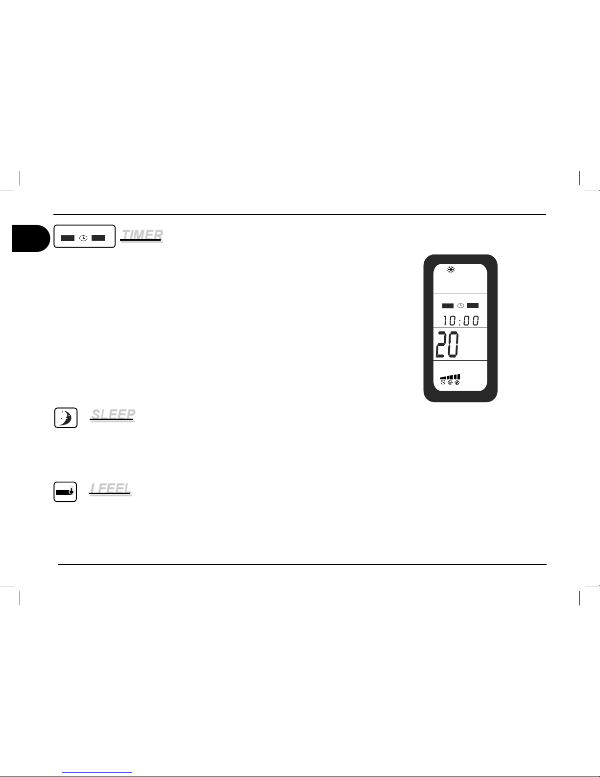
TIMER
0/
0''
Nota: Ogni volta che viene premuto il pulsante timer, il display lampeggia per 15 secondi in attesa della modifi ca dei settaggi. Ricordarsi di settare l’orologio con l’ora corretta prima di utilizzare questa funzione.
Settare il timer “ON” (accensione automatica)
1) Premere il pulsante TIMER e l’orologio ON lampeggerà.
2) Impostare l’orario desiderato tramite i tasti + e -
3) Puntare il telecomando verso il ricevitore e premere il pulsante “SET” per confermare
Settare il timer “OFF” (spegnimento automatico)
1) Premere il pulsante TIMER due volte e l’orologio OFF lampeggerà.
2) Impostare l’orario desiderato tramite i tasti + e -
3) Puntare il telecomando verso il ricevitore e premere il pulsante “SET” per confermare
Settare il timer “ON” & “OFF” (accensione e spegnimento automatico)
1) Premere il pulsante TIMER tre volte e l’orologio ON lampeggerà e l’orologio OFF sarà visibile.
2) Impostare l’orario ON desiderato tramite i tasti + e -
3) Premere il pulsante TIMER e impostare l’orario OFF desiderato tramite i tasti + e -
4) Puntare il telecomando verso il ricevitore e premere il pulsante “SET” per confermare
SLEEP
1) Selezionare la temperatura desiderata.
2) Premere il pulsante SLEEP
Nota: La funzione SLEEP varia la temperatura impostata di 1° dopo un’ora e di 2° dopo
due ore.
I FEEL
1) Premere il pulsante I FEEL per abilitare la funzione.
2) Posizionare il telecomando in modo da poter inviare i segnali al ricevitore.
3) La temperatura di funzionamento viene adeguata a quella rilevata dal telecomando.
Nota: Il telecomando non deve essere in una zona molto più calda o molto più fredda
dall’ambiente normale (ES: esposto al sole o esposto all’aria fredda del diffusore.)
I FEEL
I FEEL
¡$
0/
0''
Page 45

Istruzioni d’uso per l’utilizzatore
13
B1600 - B1600PLUS - B2200 - B2600
I
1.5.Descrizione dello stato LED sul diffusore (B1600PLUS - B2200 - B2600)
Stato LED Signifi cato
Spento Condizionatore spento
Arancio
Condizionatore in StandBy (interruttore ON - condizionatore in
attesa di comando)
Verde Condizionatore in funzione
Rosso fi sso
Anomalia - Manca l’alimentazione a 230V
(12V presente)
Rosso (1 lampeggio)
Anomalia - Malfunzionamento della sonda di temperatura E1
(interna)
Rosso (2 lampeggi)
Anomalia - Malfunzionamento della sonda di temperatura E2
(esterna)
Rosso (3 lampeggi)
Anomalia - Malfunzionamento della sonda di temperatura E3
(esterna)
Verde lampeggiante Defrost / Avvio pompa di calore (solo B2600)
Informazioni generali 1
LED
Page 46

B1600 - B1600PLUS - B2200 - B2600
14
Istruzioni d’uso per l’utilizzatore
I
1.6. Dati tecnici
* in accordo con lo standard EN 14511
Descrizione
Unità di
misura
Modello
B1600 B1600 PLUS B2200 B2600
Fluido refrigerante (tipo-quantità) vedi targhetta
Resa frigorifera W
1550* 1550* 2050* 2500*
Consumo (raffreddamento-riscaldamento) W
620-800 620-800 950-1200 1200-1350
Potenza (riscaldamento) W
800 800 1200 3300
Alimentazione di energia elettrica V-Hz
230-50 230-50 230-50 230-50
Grado di protezione IP
X4 X4 X4 X4
Volume d’aria trattata m3/h
310 310 380 380
Max volume (consigliato con pareti
isolate)
m
3
20 20 25 30
Peso Kg
30 30 34 40.5
235
650
310
min 30
1 Informazioni generali
Page 47

Istruzioni d’uso per l’utilizzatore
15
B1600 - B1600PLUS - B2200 - B2600
I
Petrol
1.7. Manutenzione ordinaria
Pulizia; eseguirla periodicamente asportando la polvere mediante un panno umido. Se neces-
sario utilizzare un detergente non aggressivo. Non utilizzare benzina o solventi.
Controllo: Eseguirlo periodicamente,
verifi cando che i fori di scarico della
condensa non siano ostruiti.
Pulizia fi ltri (1) ; eseguire questa operazione periodicamente, lavando i fi ltri con una soluzione detergente e facendoli asciugare prima di montarli.
Filtri a carboni attivi (2): Si raccomanda di effettuare la sostituzione dei fi ltri a carboni attivi almeno ogni anno.
Informazioni generali 1
Page 48

B1600 - B1600PLUS - B2200 - B2600
16
Istruzioni d’uso per l’utilizzatore
I
2 Informazioni per l’installazione
L’installazione può essere eseguita da persone con una precisa competenza tecnica. Oltre a questo requisito coloro che effettuano l’installazione
devono predisporre condizioni di lavoro adeguate al fi ne di garantire la sicurezza per se stessi e per le altre persone.
2.1. Imballo, disimballo e movimentazione
Rispettare le istruzioni riportate direttamente sull’imballo.
Sollevare il condizionatore verifi cando la sua integrità.
Non effettuare il sollevamento utilizzando le aperture di
ventilazione posteriori.
Trasferire il condizionatore nel luogo di installazione in condizioni
di sicurezza.
Page 49

Istruzioni d’uso per l’utilizzatore
17
B1600 - B1600PLUS - B2200 - B2600
I
Per l’installazione del condizionatore deve essere disponibile
un’apertura sul tetto di adeguate dimensioni. Si possono utilizzare
le aperture già presenti per la ventilazione del veicolo oppure praticarne una nuova.
In funzione delle dimensioni del veicolo e delle esigenze di aria
climatizzata, possono essere installati uno o più condizionatori.
II condizionatore deve essere montato in centro rispetto alla larghezza e alla lunghezza del veicolo.
Controllare che nella parte interna, dove prevista l’installazione,
non vi siano interferenze con l’arredamento (lampade, armadi,
porte, tende, ecc.). Questo accorgimento serve per evitare diffi -
coltà di montaggio del condizionatore e per fare in modo che il
fl usso dell’aria non incontri ostacoli.
Contattare il costruttore del veicolo per assicurarsi che
la struttura sia in grado di sopportare il carico statico e le
sollecitazioni trasmesse dal condizionatore con il veicolo in
movimento. Egli potrebbe già avere predisposto delle zone in
cui eseguire l’apertura senza il rischio di indebolire la struttura e/o tranciare cavi elettrici.
II condizionatore, preferibilmente deve essere installato
in piano. Inclinazione massima 10°.
2.2. Preparazione apertura sul tetto
2 Informazioni per l’installazione
Page 50

B1600 - B1600PLUS - B2200 - B2600
18
Istruzioni d’uso per l’utilizzatore
I
Pericolo di shock elettrico
Scollegare il veicolo da tutte le fonti di energia
Usare una apertura già esistente
1) Smontare l’oblò.
2) Pulire le superfi ci circostanti l’apertura ra-
schiando i residui di collante
3) Chiudere con silicone o stucco i fori delle
viti preesistenti ed eventuali avvallamenti.
2 Informazioni per l’installazione
Page 51

Istruzioni d’uso per l’utilizzatore
19
B1600 - B1600PLUS - B2200 - B2600
I
Informazioni per l’installazione 2
Apertura da predisporre
Tracciare la posizione e le dimensioni dell’apertura mediante il foglio prestampato in
cartone all’interno dell’imballo.
Forare negli angoli.
Tagliare unendo i fori precedentemente
praticati.
In caso di necessità inserire una cornice di
rinforzo composta da listelli di legno.
1.
2.
3.
4.
Foro per passaggio cavo
di alimentazione
Page 52

B1600 - B1600PLUS - B2200 - B2600
20
Istruzioni d’uso per l’utilizzatore
I
2.3. Montaggio del condizionatore
Adagiare il condizionatore sul tetto del
veicolo in corrispondenza dell’apertura.
Non strisciare mai il condizionatore ma
sollevarlo quando lo si muove.
N.B. Le protuberanze coniche presenti
sul fondo della base devono entrare nell’apertura del tetto
Fissare le staffe del diffusore alla base
mediante le 4 viti fornite in dotazione.
Rispettare la coppia di serraggio indicata.
Non superare mai la coppia di serraggio!
Montare le guarnizioni di collegamento
diffusore. Per determinare il corretto spessore della guarnizione seguire la tabella a
pagina 19.
Effettuare il collegamento elettrico come
mostrato nel paragrafo 2.4
2 Informazioni per l’installazione
Page 53

Istruzioni d’uso per l’utilizzatore
21
B1600 - B1600PLUS - B2200 - B2600
I
Informazioni per l’installazione 2
Fissare il diffusore alle staffe. Montare i fi ltri nell’ordine mostrato in fi -
gura
Montare i due coperchi laterali
SPESSORE DEL TETTO SPESSORE DELLA GUARNIZIONE
= 30 mm 10 mm
da 30 fi no 35 mm 15 mm
da 35 fi no 40 mm 20 mm
da 40 fi no 45 mm 25 mm
da 45 fi no 50 mm 30 mm
da 50 fi no 55 mm 35 mm
da 55 fi no 60 mm 40 mm
da 60 fi no 65 mm 45 mm
da 65 fi no 70 mm 50 mm
da 70 fi no 75 mm 55 mm
da 75 fi no 80 mm 60 mm
Page 54

B1600 - B1600PLUS - B2200 - B2600
22
Istruzioni d’uso per l’utilizzatore
I
(m)
(mm )
2
< 7,5
> 7,5
1,5
2,5
L
1
3
12V DC
230V 50Hz
B2200
2.4. Collegamento elettrico
Eseguire il collegamento elettrico rispettando le norme vigenti in materia.
Predisporre un impianto specifi co.
Collegare i cavi al condizionatore. Collegare l’impianto ad un circuito in grado di fornire l’energia richie-
sta (vedi dati tecnici) e dotato di messa a terra.
Connettore 12 poli
dalla base
Connettore 12 poli
scheda interna
diffusore
+ POLO BATTERIA
POLO BATTERIA
Cavo azzurro
Cavo marrone
Cavo giallo-verde
Cavo azzurro
Cavo marrone
Cavo giallo-verde
Linea alimentazione condizionatore
Linea alimentazione esterna
Utenze
varie
Scatola
fusibili
Commutatore
Rete/Generatore
Generatore
elettrico
Lunghezza Sezione
Interruttore
magnetotermico
RCCB
2 Informazioni per l’installazione
Page 55

Istruzioni d’uso per l’utilizzatore
23
B1600 - B1600PLUS - B2200 - B2600
I
SOLUZIONE
la temperatura è inferiore ai 18°C
la temperatura è maggiore ai 40
controllare la temperatura di Set Point
Protezione termica difettosa
Il tasto Mode non è nella giusta posizione
resistenza elettrica danneggiata
carica di gas insuffi ciente
compressore danneggiato
batterie scambio termico sporche
ventola interna difettosa
fi ltro aria ostruito
ventole esterne difettose
fori scarico condensa otturati
guarnizione di tenuta danneggiata
non arriva tensione
tensione troppo bassa (minore di 200 V)
condensatore elettrico difettoso
protezione termica difettosa
CAUSA
il condizionatore non fa freddo
il condizionatore non fa caldo
non circola più aria all'interno del mezzo
infi ltrazioni di acqua all'interno del mezzo
il condizionatore non parte
il condizionatore smette di funzionare
Operazioni eseguibili
dall’utilizzatore
Operazioni eseguibili da
personale autorizzato
3.1.Inconvenienti, cause, rimedi
3.2. Manutenzione straordinaria
Per un migliore rendimento è consigliabile far eseguire dal Vostro
rivenditore/offi cina una pulizia straordinaria prima dell’utilizzo di:
batterie di scambio termico;
fori scarico condensa.
1.
2.
3.3. Messa fuori servizio e riciclaggio
Per lo smaltimento e riciclaggio seguire le leggi nazionali. Vi invitiamo a contattare le autorità per l’ambiente o enti autorizzati.
Ricerca guasti, manutenzione, riciclaggio 3
Page 56

24
I
B1600 - B1600PLUS - B2200 - B2600
36
35
16
13
19
22
2
51
31
25
33
34
6
27
26
3
1
5
18
17
12
20
14
15
46
50
49
38
43
44
37
41
47
48
45
4
52
53
39
B2200
B1600 PLUS
46
50
49
38
42
40
37
41
47
48
45
4
52
53
39
B1600
54
55
56
57
58
59
9
8
11
7
10
32
42
40
30
29
23
24
28
21
60
61
Tavola catalogo ricambi B1600 - B1600 PLUS - B2200
Page 57

25
B1600 - B1600PLUS - B2200 - B2600
N. DESCRIZIONE
1 BASE
2 COFANO
3 RIVETTI TWO STAGE
4 ISOLANTE VASCHETTA
5 GUARNIZIONE ADESIVA
6 INSERTO
7 PIASTRA
8 PIASTRA
9 COMPRESSORE COMPLETO
10 CONDENSATORE
11 ANTIVIBRANTE
12 CABLAGGIO COMPRESSORE
13 BATTERIA EVAPORANTE
14 GUARNIZIONE ADESIVA
15 VENTILATORE
16* RESISTENZA 1100 W 230
17* BOCCOLA
18* MOLLA A COMPRESSIONE
19 TERMOSTATO
20 OR
21 RIVETTI
22 ADESIVO FRONTALE
23 CONDENSATORE
24 CONDENSATORE
25 PLENUM
26 PIASTRA FISSAGGIO VENTOLA
27 VENTILATORE RADIALE
28 MODULO DI POTENZA
29 CONDENSATORE
30 CONDENSATORE
31 BATTERIA CONDENSANTE
32 TUBO D9.52 ASPIRAZ
33 TUBO D8 MANDATA
34 KIT FILTRO
35 GUARNIZIONE
36 SCATOLA ISOLANTE
37 BASE DIFFUSORE
38 DEFLETTORE
39 GRIGLIA
40 DEFLETTORE SLITTA
41 POMELLO
42 COPERCHIO
43 SCHEDA RICEVITORE
44 COPRI-RICEVITORE
45 ADESIVO DOMETIC
46 STAFFA FISSAGGIO
47 GUARNIZIONE H.5
48 GUARNIZIONE H.10
49 GUARNIZIONE H.20
50 VITE
51 ADESIVO
52 FILTRO A CARBONI ATTIVI
53 FILTRO
54 CABLAGGIO
55 CABLAGGIO
56 PULSANTE
57 TERMOSTATO
58 POMELLO
59 GUARNIZIONE
60 TELAIO
61** SCHEDA LED
N. DESCRIZIONE N. DESCRIZIONE
I
Tavola catalogo ricambi B1600 - B1600 PLUS - B2200
* (solo per i modelli dotati di resistenza) - ** (solo per i modelli dotati di luce)
Page 58

26
I
B1600 - B1600PLUS - B2200 - B2600
Tavola catalogo ricambi B2600
14
15
20
1
3
19
47
48
49
4
37
30
29
39
45
41
44
40
42
23
38
50
43
46
21
28
51
2
22
12
36
9
10
32
35
13
24
8
11
7
6
33
31
34
27
26
5
25
16
17
18
B2600
Page 59

27
B1600 - B1600PLUS - B2200 - B2600
N. DESCRIZIONE
1 BASE
2 COFANO
3 RIVETTI TWO STAGE
4 ISOLANTE VASCHETTA
5 GUARNIZIONE ADESIVA
6 INSERTO
7 PIASTRA
8 PIASTRA
9 COMPRESSORE COMPLETO
10 CONDENSATORE
11 ANTIVIBRANTE
12 CABLAGGIO COMPRESSORE
13 BATTERIA EVAPORANTE
14 GUARNIZIONE ADESIVA
15 VENTILATORE
16 ELETTROVALVOLA
17 TUBO DI RITORNO
18 TUBO DI MANDATA
19 SCHEDA LED
20 OR
21 RIVETTI
22 ADESIVO FRONTALE
23 TELAIO
24 CABLAGGIO
25 PLENUM
26 PIASTRA FISSAGGIO VENTOLA
27 VENTILATORE RADIALE
28 MODULO DI POTENZA
29 FILTRO
30 FILTRO A CAARBONI ATTIVI
31 BATTERIA CONDENSANTE
32 TUBO D9.52 ASPIRAZ
33 TUBO D8 MANDATA
34 CAPILLARE
35 GUARNIZIONE
36 SCATOLA ISOLANTE
37 BASE DIFFUSORE
38 DEFLETTORE
39 GRIGLIA
40 DEFLETTORE SLITTA
41 POMELLO
42 COPERCHIO
43 SCHEDA RICEVITORE
44 COPRI-RICEVITORE
45 ADESIVO DOMETIC
46 STAFFA FISSAGGIO
47 GUARNIZIONE H.5
48 GUARNIZIONE H.10
49 GUARNIZIONE H.20
50 VITE
51 ADESIVO
N. DESCRIZIONE N. DESCRIZIONE
I
Tavola catalogo ricambi B2600
Page 60

B1600 - B1600PLUS - B2200 - B2600
28
Istruzioni d’uso per l’utilizzatore
I
Schema elettrico B1600
(Rev. 04)
V'
V'
V'
V'
V'
1
2
3
4
5
6
Page 61

Istruzioni d’uso per l’utilizzatore
29
B1600 - B1600PLUS - B2200 - B2600
I
Schema elettrico B1600 PLUS / B2200
NWORB
EUL
B
N
EERG-WOLLEY
CA
V032
LARTUEN - 2T
*
ENIL - 1
T
*
123
DNUORG - 3T
*
1
2
1
2
D
ER
NEERG
NAYC
WOLL
E
Y
NWORB
E
TIH
W
CKAL
B
EUL
B
YARG
TE
LOIV
RED
GREEN
CYAN
YELLOW
BROWN
WHITE
BLAK
BLUE
GRAY
VIOLET
8J
xJ
4C4C
1
2
3
4
5
6
7
8
9
01
3C3C
1234567891011
12
xJ
xC
1
2
Led
board
xJ
xC
1
2
Led
board
xJ
xC
1
2
Led
board
xJ
xC
1
2
Led
board
AIR DIFFUSER
*
* *
* *
* *
*
ROTSISE
R
T
AEH ROTSISE
R
T
AEH
H
C
T
I
WS O
M
RET H
C
T
I
WS O
M
RET
ORANGE
0/0''
0/0''
&$0/0.:
&$0/0.:
*/7&35&3
*/7&35&3
+
+
+
+
+
+
OPTIONAL CONNECTION
TO SWITCH ON THE AIR
DIFFUSER LIGHT ALSO
WHEN THERE IS NO MAIN.
PLEASE USE THE
PROVIDED CONNECTOR
PLUGGED IN THE BOARD
EUL
B
N
E
E
RG-WO
L
L
E
Y
D
E
R
KN
I
P
HCTI
W
S
OM
RE
T
HCTI
W
S
OM
RE
T
*
2F2F
*
123
*
4F4F
*
2
x
O 2xO
*
*
5F5F
*
F
u
xx Fuxx
1xO1
xO
*
1F1F
*
*
3F3F
**
*
*
1
2
3
4
COMPRESSOR
N
EERG-W
O
LLE
Y
N
EE
R
G-W
O
L
L
E
Y
K
C
A
L
B
NW
O
RB
EU
LB
1
2
3
4
FAN2 CONDERNSER
N
EE
R
G-W
O
L
L
E
Y
K
C
A
L
B
NW
O
RB
EU
LB
123
4
FAN1 CONDERNSER
KCALB
NWO
R
B
EUL
B
FAN EVAPORATOR
+ 12vdc BATTERY
- BATTERY
TEMPERATURE
PROBE
BATTERY
FUSE F2AL250V
MAIN FUSE F10AL250V
."*/'64&
."*/'64&
#"55&3:'64&
#"55&3:'64&
5&.1130#&
5&.1130#&
"694&3*"-
"694&3*"-
#"55&3:
#"55&3:
$0/%'"/
$0/%'"/
$0/%'"/
$0/%'"/
&7"1'"/
&7"1'"/
3&4*4503
3&4*4503
."*/
."*/
3&4*4503
3&4*4503
$0.13&4403
$0.13&4403
3&.05&
3&.05&
+
+
3
3
3
3
5
5
53
53
+
+
$
$
$
$
$
$
$
$
$
$
$
$
$
$
$
$
$
$
$
$
+
+
+
+
+
+
+
+
+
+
+
+
2
2
3M
3M
3M
3M
3M
3M
3M
3M
3M
3M
6
6
3
3
6
6
$
$
$
$
%;
%;
+
+
+"
+"
+#
+#
$
$
$
$
')
')
'
'
'
'
')
')
Page 62

B1600 - B1600PLUS - B2200 - B2600
30
Istruzioni d’uso per l’utilizzatore
I
Schema elettrico B2600
NWORB
EUL
B
N
EERG-WOLLEY
CA
V032
LARTUEN - 2T
*
ENIL - 1
T
*
123
DNUORG - 3T
*
121
2
D
ER
NEERG
NAYC
WOLL
E
Y
NWORB
E
TIH
W
CKAL
B
EULB
YARG
TE
LOIV
RED
GREEN
CYAN
YELLOW
BROWN
WHITE
BLAK
BLUE
GRAY
VIOLET
xJ
1
2
3
4
5
6
7
8
9
01
3C3C
1234567891011
12
xJ
xC
1
2
Led
board
xJ
xC
1
2
Led
board
xJ
xC
1
2
Led
board
xJ
xC
1
2
Led
board
AIR DIFFUSER
VALVE
ORANGE
0/0''
0/0''
&$0/0.:
&$0/0.:
*/7&35&3
*/7&35&3
OPTIONAL CONNECTION
TO SWITCH ON THE AIR
DIFFUSER LIGHT ALSO
WHEN THERE IS NO MAIN.
PLEASE USE THE
PROVIDED CONNECTOR
PLUGGED IN THE BOARD
EUL
B
N
EERG-WOLLEY
D
E
R
KN
I
P
HCTI
W
S
OM
RE
T
HCTI
W
S
OM
RE
T
*
2F2F
*
123
*
4F4F
*
2
x
O 2xO
*
*
5F5F
*
F
u
xx Fuxx
1xO1
xO
*
1F1F
*
*
3F3F
**
*
*
1
2
3
4
COMPRESSOR
N
EERG-W
O
LLE
Y
N
EE
R
G-W
O
L
L
E
Y
K
C
A
L
B
NW
O
RB
EU
LB
1
2
3
4
FAN2 CONDERNSER
N
EE
R
G-W
O
L
L
E
Y
K
C
A
L
B
NW
O
RB
EU
LB
123
4
FAN1 CONDERNSER
KCALB
NWO
R
B
EUL
B
FAN EVAPORATOR
+ 12vdc BATTERY
- BATTERY
TEMPERATURE
PROBE
BATTERY
FUSE F2AL250V
MAIN FUSE F10AL250V
."*/'64&
."*/'64&
#"55&3:'64&
#"55&3:'64&
&7"1130#&
&7"1130#&
$0/%130#&
$0/%130#&
#"55&3:
#"55&3:
"694&3*"-
"694&3*"-
$0/%'"/
$0/%'"/
$0/%'"/
$0/%'"/
&7"1'"/
&7"1'"/
)00%
)00%
."*/
."*/
$0.13&4403
$0.13&4403
7"-7&
7"-7&
3&.05&
3&.05&
3&.05&
3&.05&
+
+
Page 63

©DOMETIC - 2009 Alle Rechte vorbehalten - Gedruckt in Italien -
Kein Teil dieses Handbuchs darf ohne schriftliche Genehmigung der Fa.
DOMETIC reproduziert, kopiert oder auf sonstige Weise verbreitet werden.
Die Abbildungen, Beschreibungen, Hinweise und technischen Daten in dem
vorliegenden Handbuch sind unverbindlich und ohne Gewähr.
Die Fa. DOMETIC behält sich das Recht vor, jederzeit und ohne vorherige
Ankündigung alle Änderungen vorzunehmen, die sie im Interesse der Verbesserung des Produkts und seiner Sicherheit für angebracht hält, ohne sich
zur jedesmaligen Anpassung dieses Handbuchs zu verpfl ichten.
Bewahren Sie dieses Dokument zur späteren Verwendung auf.
Garantie
“Diese Klimaanlage ist im Sinne der gesetzlichen 1999/44/CE Regelungen hinaus garantiert.”
Die Herstellergarantie ist im Fall von Brüchen bzw. abweichendem Betrieb der Anlage ausdrücklich ausgeschlossen, die von einer falschen Montage Ursache und/oder abhängig sind.
Dem Verbraucher wird das Recht anerkannt, das Gerät selbst zu montieren. Dabei können Sie sich an die
bestimmten von Dometic aber nicht eingestellten Einzelhändler wenden.
Page 64

Normen zum Umweltschutz und zur korrekten Abfallentsorgung
Jede Firma/jeder Benutzer muss die Auswirkungen ihrer/seiner Tätigkeit (Produktion, Produkte, Dienstleistungen usw.) auf die Umwelt feststellen,
beurteilen und überwachen.
Die zur Identifi zierung von signifi kanten umweltrelevanten Auswirkungen erforderlichen Vorgangsweisen müssen die folgenden Faktoren
berücksichtigen:
- Nutzung der Rohmaterialien und der natürlichen Ressourcen
- Emissionen in die Atmosphäre
- Entsorgung der Flüssigkeiten
- Abfallentsorgung und Recycling
- Bodenkontamination
Die folgenden Hinweise und Maßnahmen sind an alle Personen gerichtet, die mit der Installation, der Nutzung, der Wartung und der Entsorgung des
Geräts zu tun haben, und müssen von diesen unbedingt beachtet werden, um die negativen Auswirkungen auf die Umwelt auf ein Mindestmaß zu
reduzieren.
- Alle Teile der Verpackung müssen den in dem Land, in dem sie entsorgt werden, geltenden gesetzlichen Bestimmungen gemäß entsorgt
(möglichst recycelt) werden.
- Alle Teile der Produkte müssen den in dem Land, in dem sie entsorgt werden, geltenden gesetzlichen Bestimmungen gemäß entsorgt
(möglichst recycelt) werden.
- Zur Gewährleistung einer korrekten Entsorgung ist das Gerät einer Spezialfi rma für Abfallentsorgung zuzuführen, die für diese Aufgabe
autorisiert ist und die Wiederverwendung der recycelbaren Teile sowie die angemessene Entsorgung der restlichen Teile sicherstellt.
- Während der Installation ist sicherzustellen, dass ein angemessener Luftaustausch im Installationsbereich stattfi ndet, um die Konzentration
verunreinigter, für die Installateure schädlicher Luft zu vermeiden.
- Bei Betrieb und Wartung des Geräts muss vermieden werden, dass
umweltschädigende Produkte (Öle, Fette usw.) in die Umwelt gelangen.
- Die akustische Belastung durch das Gerät ist möglichst gering zu halten.
Für weitere Informationen zur korrekten Demontage/Zerlegung unserer Produkte siehe entsprechende Recycling-Handbücher auf der Website
www.dometic.com/ambiente.........
Page 65

1 Allgemeine Hinweise
1.1. Zweck des Handbuchs........................................4
1.2. Identifi kation des Herstellers und der Klimaanlage...4
1.3. Beschreibung der Klimaanlage..........................4
1.4. Benutzung der Klimaanlage....................................8
1.5. Beschreibung der Kontrollen...................................9
1.6. Technische Daten................................................. 14
1.7. Pfl ege..................................................................15
2 Installationshinweise
2.1. Verpackung, Auspacken und Transport.............16
2.2. Vorbereiten einer Öffnung im Dach......................17
2.3. Befestigung der Klimaanlage...........................20
2.4. Elektroanschluß......................................22
3 Fehlersuche, Wartung, Entsorgung
3.1. Störungen, Ursachen, Abhilfen.........................23
3.2. Außerplanmäßige Wartung...........................23
3.3. Stillegung und Entsorgung...........................23
Ersatzteilliste...........................................24
SCHALTPLAN...................................................28
Inhaltsverzeichnis
Operation, Maintenance and
Installation manual
Air conditioner
GB
I
D
F
Handleiding voor bediening,
onderhoud en installatie
Airconditioner
NL
Manual de instrucciones para el uso, la manutención
y la instalación
Acondicionator
E
Livrete de instruções para uso, manutenção
e instalação
Aparelho de ar condicionado
P
Handbok för drift, underhåll och
installation
Luftkonditionering
S
Käyttö-, huolto- ja
asennusohje
Ilmastointilaite
FIN
Brukerveiledning og manual
til vedlikehold og installasjon
Airconditioner
N
DK
Libretto istruzioni per l’uso, la manutenzione e
l’installazione
Condizionatore
Bedienungs- und
Wartungsanleitung
Klimaanlage
Mise en route, entretien et
installation
Climatiseur
Brugervejledning og manual
til vedligeholdelse og installation
Airconditioner
Page 66

4
Bedienungsanleitung
D
B1600 - B1600PLUS - B2200 - B2600
1.1. Zweck des Handbuchs
Dieses Handbuch wurde vom Hersteller herausgegeben und ist als
integraler Bestandteil der Klimaanlage anzusehen.
Bei Beachtung der darin enthaltenen Informationen ist die sachgemäße
Benutzung der Klimaanlage gewährleistet.
Der erste Teil des Handbuchs richtet sich an den Benutzer , der zweite
Teil an das für die Installation der Klimaanlage zuständige Fachpersonal
Im Handbuch treten die folgenden Symbole zur Hervorhebung einiger
Textpassagen auf:
Dieser Arbeitsschritt kann Gefahren mit sich bringen.
Nützliche Vorschläge
Informationen zum Umweltschutz.
1.2. Identifi kation des Herstellers und der Klimaanlage
1.3. Beschreibung der Klimaanlag
(B1600 B1600PLUS B2200)
Die Klimaanlage wurde für die Montage auf Fahrzeugen (Caravans,
Wohnmobile, Spezialfahrzeuge usw.) entwickelt und hergestellt, um
die Raumtemperatur zu verbessern. Im Sommer erzeugt die Klimaanlage entfeuchtete Kühlluft und im Winter Warmluft, ohne je-doch die
Heizung des Fahrzeugs selbst zu ersetzen. In beiden Fällen ist die
Lufttemperatur regulierbar.
Kühlluft - Funktionsweise
Das System besteht aus: Kompressor ( a ), Kondensator ( b ), Verdampfer ( d ) und unter Druck stehender Kühlfl üssigkeit. Die Kühlfl üssigkeit
ändert ihren Aggregatzustand von fl üssig nach gasförmig und erwärmt
oder kühlt die Komponenten, durch die sie strömt.
Der abgekühlte Verdampfer wird von der vom Gebläse ( c ) getriebenen Innenraumluft durchströmt. Diese ist beim Austritt abgekühlt und
entfeuchtet.
Durch diesen Vorgang wird mit der Zeit eine Verminderung der Temperatur im Inneren des Fahrzeugs bewirkt.
Warmluft - Funktionsweise
Die Raumluft wird durch das Gebläse ( e ) über den Elektrowiderstand
( f ) geleitet, dabei erwärmt und wieder in den Raum geblasen.
1 Allgemeine Hinweise
Hersteller
Konformitätszeichen
Modell/Fabriknummer
Baujahr
Technische Daten
Page 67

Bedienungsanleitung
5
D
B1600 - B1600PLUS - B2200 - B2600
Allgemeine Hinweise 1
Kompressor (a)
Kondensator (b)
Verdampfer (d)
Heiz-Widerstand (e)
Ablauf Kondenswasser
Gebläse (c)
Zustrom von Außenluft
Zustrom von Außenluft
ausgeblasene
Warmluft
in den
Innenraum
geleitete
behandelte
Luft
Zustrom von Außenluft
Zustrom von
Raumluft
ausgeblasene
Warmluft
Page 68

6
Bedienungsanleitung
D
B1600 - B1600PLUS - B2200 - B2600
1.3. Beschreibung der Klimaanlage (B2600)
Die Klimaanlage wurde für die Montage auf Fahrzeugen (Caravans,
Wohnmobile, Spezialfahrzeuge usw.) entwickelt und hergestellt, um die
Raumtemperatur zu verbessern. Im Sommer erzeugt die Klimaanlage
entfeuchtete Kühlluft und im Winter Warmluft, ohne je-doch die Heizung
des Fahrzeugs selbst zu ersetzen. In beiden Fällen ist die Lufttempe-
ratur regulierbar.
Kühlluft - Funktionsweise
Das System besteht aus: Kompressor ( a ), Kondensator ( b ), Verdampfer ( d ) und unter Druck stehender Kühlfl üssigkeit. Die Kühlfl üssigkeit
ändert ihren Aggregatzustand von fl üssig nach gasförmig und erwärmt
oder kühlt die Komponenten, durch die sie strömt.
Der abgekühlte Verdampfer wird von der vom Gebläse ( c ) getriebenen Innenraumluft durchströmt. Diese ist beim Austritt abgekühlt und
entfeuchtet.
Durch diesen Vorgang wird mit der Zeit eine Verminderung der Temperatur im Inneren des Fahrzeugs bewirkt.
Warmluft - Funktionsbeschreibung
Über ein Magnetventil (f) ist es möglich, den Kältegaszyklus umzukehren.
Die vom Kältegas gespeicherte Wärme wird über das interne Register
abgegeben und durch den Betrieb des Gebläses (c) in den Fahrgastraum
des Fahrzeugs gefördert. Erfolgt dies über einen längeren Zeitraum,
erhöht sich die Temperatur innerhalb des Fahrzeugs.
Page 69

Bedienungsanleitung
7
D
B1600 - B1600PLUS - B2200 - B2600
Allgemeine Hinweise 1
Kompressor (a)
Kondensator (b)
Verdampfer (d)
Ablauf Kondenswasser
Gebläse (c)
Zustrom von Außenluft
Zustrom von Au
ßenluft
ausgeblasene
Warmluft
in den
Innenraum
geleitete
behandelte
Luft
Zustrom von Außenluft
Zustrom von
Raumluft
ausgeblasene
Warmluft
Magnetventil (f)
Page 70

8
Bedienungsanleitung
D
B1600 - B1600PLUS - B2200 - B2600
1.4. Benutzung der Klimaanlage
Die Leistung der Klimaanlage kann mit einigen einfachen Vorkeh-
rungen verbessert werden.
Die Wärmeisolierung des Fahrzeugs verbessern, indem man Ritzen abdichtet und Glasfl ächen mit refl ektierenden Vorhängen isoliert.
Unnötiges Öffnen von Türen und Fenstern vermeiden.
Eine angemessene Temperatur und Lüftungsgeschwindigkeit wählen.
Die Luftleitbleche in geeigneter Weise ausrichten.
Um Betriebsstörungen der Klimaanlage und Gefahren für Personen zu
vermeiden:
keine Tücher, Papier oder Gegenstände in die Luftein- und -austritte
stecken;
weder Finger noch Gegenstände in die Schlitze der Lüftungsöffnung
stecken;
kein Wasser in das Innere der Klimaanlage spritzen;
alle leicht brennbaren Materialien aus der Nähe der Klimaanlage en-
tfernen.
•
•
•
•
•
•
•
•
Regolierung und Ausgleichung der Luftfl ussrichtung
Die beiden Umlenker auf die gewünschte Position ausrichten. Aufdrehen des mittleren Drehknopfes entgegen dem Uhrzeigersinn. Nach der
gewünschten Einstellung wieder den Drehknopf im Uhrzeigersinn feststellen.
1 Allgemeine Hinweise
Page 71

Bedienungsanleitung
9
D
B1600 - B1600PLUS - B2200 - B2600
1.5.Beschreibung der Kontrollen (B1600)
Allgemeine Hinweise 1
*
* (nür für Modelle mit Widerstand)
Page 72

10
Bedienungsanleitung
D
B1600 - B1600PLUS - B2200 - B2600
on/off
LÜFTUNG
Licht**
Betriebsart
Lüftungsgeschwindigkeit
Telecomando (B2200 B1600PLUS B2600)
ON/OFF
Um die Klimaanlage einzuschalten ist die Taste ON/
OFF zu betätigen. Ist Diese ausgeschaltet, so sind
ausser der Uhranzeige alle Symbole abgeschaltet
und es sind nur die Tasten ROOM und LIGHT**
verfügbar.
F°/C°
F°/C°
Wählen der Temperatur-Einheit zwischen Celcius
(°C) und Fahrenheit (°F).
Diese Funktion ist nur in Tätigkeit wenn die Temperatur auf dem Display erscheint.
LIGHT
LIGHT
LIGHT**
(Soweit vorhanden) Durch betätigen dieser Taste wird
das Licht des Diffusers an- bzw. ausgemacht.
Diese Taste ist auch bei ausgeschaltener Fernbedienung funktionsfähig.
ROOM
ROOM
Diese Taste macht die Innentemperatur sichtbar
(Symbol “ROOM”). Durch wiederholtes drücken
dieser Taste kommt man wieder zum set point
(Ausgangspunkt) zurück. Diese Taste ist auch bei
ausgeschaltener Fernbedienung funktionsfähig.
CLOCK
CLOCK
Um die Uhrzeit einzustellen (Tasten + und -) Taste
mehr als 2 Sekunden lang gedrückt halten. Die Einstellungen dann mit der Taste “SET“ abspeichern.
Nach 15 Sekunden werden dann jeweils die letzten
Änderungen automatisch abgespeichert.
SET
SET
Diese Taste hat 2 Funktionen:
1) Bestätigung der eingestellten Uhrzeit.
2)Durch wiederholtes betätigen werden die letzten
aktuellen Daten übermittelt.
TIMER
TIMER
Durch Drücken dieser Taste kann die Zeit für das automatische Ein- und/oder Abschalten eingestellt werden.
SLEEP
SLEEP
Durch Drücken dieser Taste wird die SLEEP-Funktion
aktiviert. Der Sollwert wird automatisch geregelt, um
eine angenehme Schlaftemperatur zu gewährleisten .
I FEEL
I FEEL
Der Betriebssollwert wird alle 10 Minuten an die von
der Fernbedienung gemessene Temperatur angepasst.
Die Taste “RESET” setzt alle Änderungen wieder zurück auf die
Grundeinstellung.
+
-
MODE
¡$
CLOCK
TIMER
SET
SLEEP
I FEEL
ROOM
F°/C°
LIGHT
LIGHT
IFEEL
IFEEL
0/
0''
Symbol für
Batterien
entladen
Taktgeber
Set Point
Taktgeber
F°/C°
Set
Room
Reset
Raumtemperatur
Betriebsart
(+)
(-)
I Feel
Timer
Sleep
Sleep
I Feel
Timer
1.5.Beschreibung der Kontrollen
1 Allgemeine Hinweise
* (nür für Modelle mit Widerstand) - ** (nür für Modelle mit Licht)
Page 73

Bedienungsanleitung
11
D
B1600 - B1600PLUS - B2200 - B2600
Allgemeine Hinweise 1
AUTOMATISCHE BETRIEBSART
¡$
AUTO
BETRIEBSART KALT/WARM*
BETRIEBSART LŰFTUNG
¡$ ¡$
30%%$
30%%$
30%%$
30%%$
Verfügbare Lüftergeschwindigkeit (Kalt/Warm/Ventilation)
MODE
Taste MODE so oft betätigen, bis “AUTO” erscheint.
+
-
Wählen der Gewünschten
Temperatur (Set Point)
(16°C - 31°C)
Bei dieser Modalität ist die Taste (fan) nicht
aktiv. Man kann aber die Tasten LIGHT** und
ROOM verwenden.
MODE
Betätigung der Taste MODE:
“KALT“ oder “WARM“*
wählen
+
-
Wählen der Gewünschten
Temperatur (Set Point)
(16°C - 31°C)
Wählen der Lüftergeschwindigkeit.
Es können die Tasten LIGHT** und ROOM
verwendet werden.
MODE
Betätigen der Taste
MODE. Wählen der
Lüftereinstellung.
Wählen der Lüftergeschwindigkeit.
Batterien Entladen
Wenn die Batterien entladen
sind erscheint auf dem Display
ein entsprechendes Symbol.
Nach jeder Eingabe blinkt das
entsprechende Symbol für 2
Sekunden.
BATTERYCOMPARTMENT
ON BACK SIDE OF REMOTE
CONTROL
1
234
O
F
F
OFF
Batterien austauschen
2x1.5V AAA
Es können die Tasten LIGHT** und ROOM
verwendet werden.
* (nür für Modelle mit Widerstand) - ** (nür für Modelle mit Licht)
Page 74

12
Bedienungsanleitung
D
B1600 - B1600PLUS - B2200 - B2600
TIMER
0/
0''
Anm.: Mit jedem Drücken der Timer-Taste blinkt das Display 15 Sekunden lang und wartet auf eine Eingabe.
Vor der Benutzung dieser Funktion muss die Uhr korrekt eingestellt werden.
Einstellen des Timers “ON” (automatische Einschaltung)
1) Die Taste TIMER drücken - die Zeitanzeige für ON beginnt zu blinken.
2) Mit den Tasten + und - die gewünschte Uhrzeit einstellen.
3) Die Fernbedienung auf den Empfänger ausrichten und die Einstellung mit der Taste “SET” bestätigen.
Einstellen des Timers “OFF” (automatische Abschaltung)
1) Die Taste TIMER zwei Mal drücken - die Zeitangabe OFF beginnt zu blinken.
2) Mit den Tasten + und - die gewünschte Uhrzeit einstellen.
3) Die Fernbedienung auf den Empfänger richten und die Einstellung mit der Taste “SET” bestätigen.
Einstellen des Timers “ON” & “OFF” (Automatische Ein- und Ausschaltung)
1) Die Taste TIMER drei Mal drücken - die Zeitanzeige ON blinkt und die Zeitanzeige OFF ist sichtbar.
2) Mit den Tasten + und - die gewünschte Einschaltzeit ON einstellen.
3) Die Taste TIMER drücken und die gewünschte Uhrzeit OFF mit den Tasten + und - einstellen.
4) Die Fernbedienung auf den Empfänger richten und die Eingabe mit der Taste “SET” bestätigen.
SLEEP
1) Die gewünschte Tempertur einstellen.
2) Die Taste SLEEP drücken.
Anm.: Die Funktion SLEEP ändert die eingestellte Temperatur nach einer Stunde um 1°
und nach zwei Stunden um 2°.
I FEEL
1) Durch Drücken der Taste I FEEL wird die Funktion aktiviert.
2) Die Fernbedienung so positionieren, dass die Signale an den Empfänger gesendet werden
können.
3) Die Betriebstemperatur wird der von der Fernbedienung gemessenen Temperatur angepasst.
Anm.: Die Fernbedienung darf sich nicht in eine Bereich des Raums befi nden, in dem es wesen-
tlich heißer oder kälter ist als die durchschnittliche Raumtemperatur (z. B. in der Sonne oder vor
der Klimaanlage ).
I FEEL
I FEEL
¡$
0/
0''
1 Allgemeine Hinweise
Page 75

Bedienungsanleitung
13
D
B1600 - B1600PLUS - B2200 - B2600
LED
Allgemeine Hinweise 1
1.5 Zustandsbeschreibung der Lüfter-Leuchtidiode (LED) (B1600PLUS - B2200 - B2600)
Zustand LED Bedeutung
Aus Klimaanlage aus
Orange
Klimaanlage in StandBy
(Schalter AN - Kliamanlage in Bedienungs-Wartestellung)
Grün Klimaanlage in Betrieb
Rot durchgehend
Anomalie – es fehlt der Stromanschluß über 230V
(12V vorhanden)
Rot (einfaches blinken) Anomalie – Funktionsstörung der Temperatursonde E1 (Innen)
Rot (doppeltes blinken) Anomalie – Funktionsstörung der Temperatursonde E2 (Aussen)
Rot (doeifaches blinken) Anomalie – Funktionsstörung der Temperatursonde E3 (Aussen)
Grün blinkend Entfrosten / Start der Wärmepumpe (nur B2600)
Page 76

14
Bedienungsanleitung
D
B1600 - B1600PLUS - B2200 - B2600
1.6. Technische Daten
1 Allgemeine Hinweise
* Entsprechend EN 14511
Benennung Maßeinheit
Model
B1600 B1600 PLUS B2200 B2600
Kühlgas (Typ-Menge) siehe typenschild
Kühlleistung W 1500* 1500* 2050* 2500*
Verbrauch für Kühlung-Heiz W 620-800 620-800 950-1200 1200-1350
Heizleistung W 800 800 1200 3300
Elektroanschluss V-Hz 230-50 230-50 230-50 230-50
Schutzklasse IP X4 X4 X4 X4
Volumen der behandelten Luft m
3
/h 310 310 380 380
Max. Fahrzeugvolumen
(mit isolierten Wänden)
m
3
20 20 25 30
Gewicht Kg 30 30 34 40.5
235
650
310
min 30
Page 77

Bedienungsanleitung
15
D
B1600 - B1600PLUS - B2200 - B2600
Allgemeine Hinweise 1
Petrol
1.7. Pfl ege
Reinigung: Regelmäßig mit einem feuchten Lappen den Staub entfernen. Falls nötig, ein
schonendes Putzmittel verwenden. Kein Dieselöl, Benzin oder Lösungsmittel verwenden.
Kontrolle: Regelmäßig überprüfen, ob
die Ablaufl öcher für das Kondenswas-
ser verstopft sind.
Filterreinigung(1): Regelmäßig den Filter mit einer Waschmittellösung spülen und vor dem Wiedereinsetzen trocknen lassen.
Aktivkohlefi lter(2): Es wird dem ersatz der Aktivkohlefi lter mindestens jedes Jahr empfohlen.
Page 78

16
Bedienungsanleitung
D
B1600 - B1600PLUS - B2200 - B2600
2 Installationshinweise
Die Installation darf nur von autorisiertem Fachpersonal durchgeführt werden. Der Installateur muß für ausreichende Schutzmaßnahmen sorgen,
um die Sicherheit für sich und andere Personen zu gewährleisten.
2.1. Verpackung, Auspacken und Transport
Die direkt auf der Verpackung stehenden Hinweise beachten.
Beim Anheben die Klimaanlage auf eventuelle Beschädigungen
Überprüfen.
Zum Anheben nicht die hinteren Lüftungsschlitze verwenden.
Die Klimaanlage unter Beachtung der Sicherheitsbestimmungen
an den Installationsort transportieren.
Page 79

Bedienungsanleitung
17
D
B1600 - B1600PLUS - B2200 - B2600
Für die Installation der Klimaanlage muß im Dach eine Öffnung
von geeigneter Größe vorbereitet werden. Man kann entweder die
vorhandenen Dachluken verwenden oder eine ganz neue Öffnung
schneiden
Man kann je nach den Maßen des Fahrzeuges und dem Lüftungsbedarf eine oder mehrere Anlagen installieren. Die Klimaanlage sollte in bezug auf die breite des fahrzeugs mittig angebracht
werden.
Vor Installation überprüfen, daß es im Fahrzeuginneren zu keiner
Kollision mit der Einrichtung kommt (Lampen, Schränke, Türen,
Vorhänge usw.). Diese Kontrolle soll Schwierigkeiten bei der Montage vermeiden und dafür sorgen, daß der Luftstrom auf keine
Hindernisse trifft.
In Verbindung mit dem Fahrzeughersteller sicherstellen, daß der Aufbau in der Lage ist, das statische Gewicht
und die Belastungen durch die Klimaanlage bei in Bewegung
befi ndlichem Fahrzeug auszuhalten. Dieser hat eventuell
bereits Stellen vorgesehen, wo die Öffnung ohne Gefahr
der Schwächung des Aufbaus bzw. des Durchtrennen von
Stromkabeln abgebracht werden kann.
Die Klimaanlage soll nach Möglichkeit eben installiert
werden. Maximale Neigung 10°
2.2. Vorbereiten einer Öffnung im Dach
Installationshinweise 2
Page 80

18
Bedienungsanleitung
D
B1600 - B1600PLUS - B2200 - B2600
Gefahr von Stromschlägen
Das Fahrzeug von allen Energiequellen trennen.
Bereits vorhandene Dachluken
1) Den Lukendeckel abmontieren.
2) Die Oberfl äche um die Öffnung reinigen
und Klebstoffreste entfernen.
3) Vorhandene Schraubenlöcher und eventuel-le Eintiefungen mit Silikon oder Dichtmaße schließen.
2 Installationshinweise
Page 81

Bedienungsanleitung
19
D
B1600 - B1600PLUS - B2200 - B2600
Installationshinweise 2
Neue Lüftungsöffnung
Lage und Größe der Öffnung mit Hilfe der in
der Verpackung enthaltenen vorgedruckten
Kartonschablone aufzeichnen.
Die Ecken ausbohren.
Durch Verbinden der vorgebohrten Löcher
ausschneiden.
Falls nötig, einen Verstärkungsrahmen aus
Holzleisten einsetzen.
1.
2.
3.
4.
Durchgangöffnung für
Stromkabel bohren
Page 82

20
Bedienungsanleitung
D
B1600 - B1600PLUS - B2200 - B2600
2.3. Befestigung der Klimaanlage
Die Klimaanlage über die Öffnung auf
dem Fahrzeugdach stellen. Die Klimaanlage nie ziehen, sondern zum Fortbewegen immer anheben.
Hinweis: Die kegelförmigen Zapfen unten an der Grundplatte müssen in die
Dachöffnung eingeführt werden.
Die Anbausätze des Lüfters mit den 4
mitgelieferten Gewindeschneitschrauben
an der Grundplatte befestigen.
Das angegebene Anzugsmoment
einhalten. Niemals das Anzugsmoment
überschreiten!
Montieren der Verbindungsdichtungen zur
Luftverteilerbox. Um die richtige Stärke der
Dichtungen zu bestimmen bitte die Tabelle
auf Seite 19 benutzen.
Den Elektroanschluss herstellen, wie in
Paragraph 2.4 gezeigt.
2 Installationshinweise
Page 83

Bedienungsanleitung
21
D
B1600 - B1600PLUS - B2200 - B2600
Installationshinweise 2
Befestigen der Luftverteilerbox an den
Haltewinkeln.
Die Filter in der Reihenfolge der Abbildung montieren.
Anbringen der beiden seitlichen Abdeckungen.
Wandstärke des Daches Dicke der Dichtung
= 30 mm 10 mm
Zwischen 30 Und 35 mm 15 mm
Zwischen 35 Und 40 mm 20 mm
Zwischen 40 Und 45 mm 25 mm
Zwischen 45 Und 50 mm 30 mm
Zwischen 50 Und 55 mm 35 mm
Zwischen 55 Und 60 mm 40 mm
Zwischen 60 Und 65 mm 45 mm
Zwischen 65 Und 70 mm 50 mm
Zwischen 70 Und 75 mm 55 mm
Zwischen 75 Und 80 mm 60 mm
Page 84

22
Bedienungsanleitung
D
B1600 - B1600PLUS - B2200 - B2600
2.4. Elektroanschluß
Den Elektroanschluß unter Beachtung der einschlägig geltenden Bestimmungen herstellen.
Eine spezifi sche Anlage vorbereiten.
Die Kabel an die Klimaanlage anschließen. Die Anlage an einen Stromkreis anschließen, der in der Lage ist, die
erforderliche Energie zu liefern (siehe technische Daten), und eine
Erdung besitzt.
ROTARENEGMORT3
RETLAHCSM5
ROTARENE'ZTE.
GNUTIELSGNUGROSREVZTE.
ENEDEIHCSRE6
REHCUARBRE
6
çSGNUREHCI3
NETSAK
FHOÊ-
UUJOIDTSFV2
EGALNAA
MIL
+GNUTIE
LSG
NUGROSRE6
QPMJHFS
4UFDLWFSCJOEFS
12V DC
#SBVO,BCFM
230V 50Hz
10-#"55&3*&
10-#"55&3*&
$ZBO,BCFM
(FMC(SàO,BCFM
QPMJHFS
4UFDLWFSCJOEFS
#SBVO,BCFM
$ZBO,BCFM
(FMC(SàO,BCFM
B2200
2 Installationshinweise
Page 85

Bedienungsanleitung
23
D
B1600 - B1600PLUS - B2200 - B2600
ABHILFEN
Die Temperatur liegt unter 16°C
Die Temperatur liegt über 30°C
Kontrollieren eingestellte temperatur
Der Thermoschutz ist defekt
Der Umschalter ist nicht in der richtigen
Position
Elektrowiderstand schadhaft
Ungenügende Gaszufuhr
Kompressor schadhaft
Wärmetauscherbatterie verschmutzt
Inneres Flügelrad schadhaft
Luftfi lter verstopft
Äußeres Flügelrad schadhaft
Ablaufl öcher Kondenswasser verstopft
Dichtung schadhaft
Es liegt keine Spannung an
Spannung zu niedrig (unter 200 V)
Elektrokondensator schadhaft
Thermoschalter schadhaft
STÖRUNGEN
Die Klimaanlage kühlt nicht
Die Klimaanlage wärmt nicht
Keine Luftzirkulation mehr im Fahrzeug
Wassereintritt im Fahrzeug
Die Klimaanlage springt nicht an
Die Klimaanlage schaltet nicht ab
Vom Benutzer ausführbare
Tätigkeiten
Von autorisiertem Personal
auszuführende Tätigkeiten
3.1.Störungen, Ursachen, Abhilfen
3.2. Außerplanmäßige Wartung
Um eine bessere Leistung zu erzielen, empfi ehlt es sich, vor dem
Einsatz eine außerplanmäßige Reinigung durch Ihren Händler/
Werkstätte durchf hren zu lassen; insbesondere:
Wärmetauscherbatterie;
Ablaufl öcher Kondenswasser.
1.
2.
3.3. Stillegung und Entsorgung
Für die Entsorgung und Wiederverwendung die nationalen Bestimmungen beachten. Wir bitten Sie, sich an die Umweltschutzbehörden oder an autorisierte Stellen zu wenden.
Fehlersuche, Wartung, Entsorgung 3
Page 86

24
D
B1600 - B1600PLUS - B2200 - B2600
Ersatzteilliste B1600 - B1600 PLUS - B2200
36
35
16
13
19
22
2
51
31
25
33
34
6
27
26
3
1
5
18
17
12
20
14
15
46
50
49
38
43
44
37
41
47
48
45
4
52
53
39
B2200
B1600 PLUS
46
50
49
38
42
40
37
41
47
48
45
4
52
53
39
B1600
54
55
56
57
58
59
9
8
11
7
10
32
42
40
30
29
23
24
28
21
60
61
Page 87

B1600 - B2200
25
D
B1600 - B1600PLUS - B2200 - B2600
N. Benennung
1
Gehäuseunterteil
2
Abdeckung
3 rivets two stage
4
Isolation
5
Dichtung
6 insert
7
Halter
8
Halter
9
Kompressor
10
Kondensator
11
Vibrationsdämpfer
12
Verkabelung
13
Verdampfer
14
Dichtung
15
Ventilator
16*
Widerstand
17*
Dichtung
18*
Feder
19
Thermostat
20 or
21 Rivets
22
Aufkleber
23
Kondensator
24
Kondensator
25 Plenum
26
Halter
27
Ventilator
28 Relais-Modul
29
Kondensator
30
Kondensator
31
Kondensator
32
Rohr
33
Rohr
34
Filter Kit
35
Dichtung
36
Styroporabdeckung
37
Luftverteilerbox
38
Luftstrom-Umlenker
39 Gitter
40
Luftstrom-Umlenker
41 Drehknopf
42 Deckel
43 Empänbgermodul
44
Schutz
45 Aufkleber
46
Halter
47 Dichtung H.5
48
Dichtung H.10
49
Dichtung H.20
50
Schraube
51 Aufkleber
52
Aktivkohlefi lter
53 Filter
54 Verkabelung
55 Verkabelung
56 Schalter
57 Thermostat
58 Thermostat knopf
59
Dichtung
60 Halterung
61** Ledmodul
N. Benennung N. Benennung
Ersatzteilliste B1600 - B1600 PLUS - B2200
* (nür für Modelle mit Widerstand) - ** (nür für Modelle mit Licht)
Page 88

26
D
B1600 - B1600PLUS - B2200 - B2600
14
15
20
1
3
19
47
48
49
4
37
30
29
39
45
41
44
40
42
23
38
50
43
46
21
28
51
2
22
12
36
9
10
32
35
13
24
8
11
7
6
33
31
34
27
26
5
25
16
17
18
B2600
Ersatzteilliste B2600
Page 89

B1600 - B2200
27
D
B1600 - B1600PLUS - B2200 - B2600
N. Benennung
1
Gehäuseunterteil
2
Abdeckung
3 rivets two stage
4
Isolation
5
Dichtung
6 insert
7
Halter
8
Halter
9
Kompressor
10
Kondensator
11
Vibrationsdämpfer
12
Verkabelung
13
Verdampfer
14
Dichtung
15
Ventilator
16 Magnetventil
17 RÜCKLAUFLEITUNG
18 VORLAUFLEITUNG
19 Ledmodul
20 or
21 Rivets
22
Aufkleber
23 Halterung
24 Verkabelung
25 Plenum
26
Halter
27
Ventilator
28 Relais-Modul
29
Filter
30
Aktivkohlefi lter
31
Kondensator
32
Rohr
33
Rohr
34 HAARRÖHRE
35
Dichtung
36
Styroporabdeckung
37
Luftverteilerbox
38
Luftstrom-Umlenker
39 Gitter
40
Luftstrom-Umlenker
41 Drehknopf
42 Deckel
43 Empänbgermodul
44
Schutz
45 Aufkleber
46
Halter
47 Dichtung H.5
48
Dichtung H.10
49
Dichtung H.20
50
Schraube
51 Aufkleber
N. Benennung N. Benennung
Ersatzteilliste B2600
Page 90

28
Bedienungsanleitung
D
B1600 - B1600PLUS - B2200 - B2600
SCHALTPLAN B1600
(Rev. 04)
V'
V'
V'
V'
V'
1
2
3
4
5
6
Page 91

Bedienungsanleitung
29
D
B1600 - B1600PLUS - B2200 - B2600
SCHALTPLAN B1600 PLUS / B2200
NWORB
EUL
B
N
EERG-WOLLEY
CA
V032
LARTUEN - 2T
*
ENIL - 1
T
*
123
DNUORG - 3T
*
1
2
1
2
D
ER
NEERG
NAYC
WOLL
E
Y
NWORB
E
TIH
W
CKAL
B
EUL
B
YARG
TE
LOIV
RED
GREEN
CYAN
YELLOW
BROWN
WHITE
BLAK
BLUE
GRAY
VIOLET
8J
xJ
4C4C
1
2
3
4
5
6
7
8
9
01
3C3C
1234567891011
12
xJ
xC
1
2
Led
board
xJ
xC
1
2
Led
board
xJ
xC
1
2
Led
board
xJ
xC
1
2
Led
board
AIR DIFFUSER
*
* *
* *
* *
*
ROTSISE
R
T
AEH ROTSISE
R
T
AEH
H
C
T
I
WS O
M
RET H
C
T
I
WS O
M
RET
ORANGE
0/0''
0/0''
&$0/0.:
&$0/0.:
*/7&35&3
*/7&35&3
+
+
+
+
+
+
OPTIONAL CONNECTION
TO SWITCH ON THE AIR
DIFFUSER LIGHT ALSO
WHEN THERE IS NO MAIN.
PLEASE USE THE
PROVIDED CONNECTOR
PLUGGED IN THE BOARD
EUL
B
N
E
E
RG-WO
L
L
E
Y
D
E
R
KN
I
P
HCTI
W
S
OM
RE
T
HCTI
W
S
OM
RE
T
*
2F2F
*
123
*
4F4F
*
2
x
O 2xO
*
*
5F5F
*
F
u
xx Fuxx
1xO1
xO
*
1F1F
*
*
3F3F
**
*
*
1
2
3
4
COMPRESSOR
N
EERG-W
O
LLE
Y
N
EE
R
G-W
O
L
L
E
Y
K
C
A
L
B
NW
O
RB
EU
LB
1
2
3
4
FAN2 CONDERNSER
N
EE
R
G-W
O
L
L
E
Y
K
C
A
L
B
NW
O
RB
EU
LB
123
4
FAN1 CONDERNSER
KCALB
NWO
R
B
EUL
B
FAN EVAPORATOR
+ 12vdc BATTERY
- BATTERY
TEMPERATURE
PROBE
BATTERY
FUSE F2AL250V
MAIN FUSE F10AL250V
."*/'64&
."*/'64&
#"55&3:'64&
#"55&3:'64&
5&.1130#&
5&.1130#&
"694&3*"-
"694&3*"-
#"55&3:
#"55&3:
$0/%'"/
$0/%'"/
$0/%'"/
$0/%'"/
&7"1'"/
&7"1'"/
3&4*4503
3&4*4503
."*/
."*/
3&4*4503
3&4*4503
$0.13&4403
$0.13&4403
3&.05&
3&.05&
+
+
3
3
3
3
5
5
53
53
+
+
$
$
$
$
$
$
$
$
$
$
$
$
$
$
$
$
$
$
$
$
+
+
+
+
+
+
+
+
+
+
+
+
2
2
3M
3M
3M
3M
3M
3M
3M
3M
3M
3M
6
6
3
3
6
6
$
$
$
$
%;
%;
+
+
+"
+"
+#
+#
$
$
$
$
')
')
'
'
'
'
')
')
Page 92

30
Bedienungsanleitung
D
B1600 - B1600PLUS - B2200 - B2600
SCHALTPLAN B2600
NWORB
EUL
B
N
EERG-WOLLEY
CA
V032
LARTUEN - 2T
*
ENIL - 1
T
*
123
DNUORG - 3T
*
121
2
D
ER
NEERG
NAYC
WOLL
E
Y
NWORB
E
TIH
W
CKAL
B
EULB
YARG
TE
LOIV
RED
GREEN
CYAN
YELLOW
BROWN
WHITE
BLAK
BLUE
GRAY
VIOLET
xJ
1
2
3
4
5
6
7
8
9
01
3C3C
1234567891011
12
xJ
xC
1
2
Led
board
xJ
xC
1
2
Led
board
xJ
xC
1
2
Led
board
xJ
xC
1
2
Led
board
AIR DIFFUSER
VALVE
ORANGE
0/0''
0/0''
&$0/0.:
&$0/0.:
*/7&35&3
*/7&35&3
OPTIONAL CONNECTION
TO SWITCH ON THE AIR
DIFFUSER LIGHT ALSO
WHEN THERE IS NO MAIN.
PLEASE USE THE
PROVIDED CONNECTOR
PLUGGED IN THE BOARD
EUL
B
N
EERG-WOLLEY
D
E
R
KN
I
P
HCTI
W
S
OM
RE
T
HCTI
W
S
OM
RE
T
*
2F2F
*
123
*
4F4F
*
2
x
O 2xO
*
*
5F5F
*
F
u
xx Fuxx
1xO1
xO
*
1F1F
*
*
3F3F
**
*
*
1
2
3
4
COMPRESSOR
N
EERG-W
O
LLE
Y
N
EE
R
G-W
O
L
L
E
Y
K
C
A
L
B
NW
O
RB
EU
LB
1
2
3
4
FAN2 CONDERNSER
N
EE
R
G-W
O
L
L
E
Y
K
C
A
L
B
NW
O
RB
EU
LB
123
4
FAN1 CONDERNSER
KCALB
NWO
R
B
EUL
B
FAN EVAPORATOR
+ 12vdc BATTERY
- BATTERY
TEMPERATURE
PROBE
BATTERY
FUSE F2AL250V
MAIN FUSE F10AL250V
."*/'64&
."*/'64&
#"55&3:'64&
#"55&3:'64&
&7"1130#&
&7"1130#&
$0/%130#&
$0/%130#&
#"55&3:
#"55&3:
"694&3*"-
"694&3*"-
$0/%'"/
$0/%'"/
$0/%'"/
$0/%'"/
&7"1'"/
&7"1'"/
)00%
)00%
."*/
."*/
$0.13&4403
$0.13&4403
7"-7&
7"-7&
3&.05&
3&.05&
3&.05&
3&.05&
+
+
Page 93

©DOMETIC - 2009 Tutti i diritti riservati - Stampato in Italia -
Toute reproduction même partielle de ce manuel ne peut être effectuée sans
l’accord écrit de DOMETIC.
Schémas, descriptions et données techniques sont données à titre indicatif et
peuvent tre modifi ées sans préavis.
Conserver ce document pour tout usage futur.
Validité Garantie
“Le produit est garantit d’après la Loi et les normes promulguées pour la transposition en droit interne de la Directive 1999/44/CE.”
La garantie du Producteur est expressément caduque en cas de rupture et/ou de fonctionnement anormal du
Produit dérivant et/ou dépendant d’un montage incorrect.
Le Consommateur a le droit de faire effectuer le montage du Produit par des revendeurs autorisés mais non
directement dépendants de la société Dometic.
Page 94

Règles concernant la sécurité de l’impact sur l’environnement et l’élimination correcte
Toute organisation doit appliquer des procédures pour identifi er, évaluer et contrôler l’infl uence de ses activités (produits, services, etc.) sur
l’environnement.
Les procédures à suivre pour identifi er les impacts signifi catifs sur l’environnement doivent tenir compte des facteurs suivants:
- Utilisation des matières première et des ressources naturelles
- émissions dans l’atmosphère
- écoulements des liquides
- gestion des déchets et recyclage
- contamination du sol
Afi n de minimiser l’impact sur l’environnement, le constructeur fournit ci-après des indications dont devront tenir compte tous ceux qui interagissent à
quelque titre que ce soit avec l’appareil durant sa période de vie prévue.
- tous les composants de l’emballage doivent être éliminés (si possible recyclés) conformément aux lois en vigueur dans le pays où
l’emballage en question est éliminé.
- tous les composants du produit doivent être éliminés (si possible recyclés) conformément aux lois en vigueur dans le pays où l’emballage
en question est éliminé.
- pour une élimination correcte, l’appareil devrait être transféré à une entreprise d’élimination des déchets autorisée dans le but d’assurer la
réutilisation des composants recyclables et une élimination adéquate des composants restant
- pendant la phase d’installation faire en sorte que l’environnement a un renouvellement de l’air adéquat pour éviter la concentration d’air
insalubre pour les opérateurs
- en phase d’utilisation et d’entretien éviter de disperser les produits polluants dans la
nature (huiles, graisses etc.)
- Le niveau du bruit doit être maintenu au niveau minimum pour réduire les nuisances sonores
Pour plus d’indications sur le démantèlement correct de nos produits faire référence aux manuels de recyclage sur www.dometic.com/
ambiente.........
Page 95

1 Informations générales
1.1. Contenu du manuel.............................................4
1.2. Plaque d’identifi cation.......................................4
1.3. Description du climatiseur...................................4
1.4. Utilisation du climatiseur..........................................8
1.5. Description des commandes................................. 9
1.6. Caractéristiques techniques...............................14
1.7. Maintenance......................................................15
2 Instructions d’installation
2.1. Emballage déballage et installation.....................16
2.2. Préparation de l’ouverture du toit ........................17
2.3. Montage du climatiseur.................................20
2.4. Connections électriques.....................................22
3 Pannes, entretien, recyclage
3.1. Pannes , causes , solutions............................. 23
3.2. Entretien spécial...............................................23
3.3. Recyclage..................................................23
Liste de pieces detachees ..............................24
SCHEMA ELECTRIQUE.................................28
Index
Operation, Maintenance and
Installation manual
Air conditioner
GB
I
D
F
Handleiding voor bediening,
onderhoud en installatie
Airconditioner
NL
Manual de instrucciones para el uso, la manutención
y la instalación
Acondicionator
E
Livrete de instruções para uso, manutenção
e instalação
Aparelho de ar condicionado
P
Handbok för drift, underhåll och
installation
Luftkonditionering
S
Käyttö-, huolto- ja
asennusohje
Ilmastointilaite
FIN
Brukerveiledning og manual
til vedlikehold og installasjon
Airconditioner
N
DK
Libretto istruzioni per l’uso, la manutenzione e
l’installazione
Condizionatore
Bedienungs- und
Wartungsanleitung
Klimaanlage
Mise en route, entretien et
installation
Climatiseur
Brugervejledning og manual
til vedligeholdelse og installation
Airconditioner
Page 96

4
manuel d’utilisation
F
B1600 - B1600PLUS - B2200 - B2600
1.1. Contenu du manuel
Ce manuel a été conçu par le fabriquant et doit être considéré comme
indissociable du climatiseur .
Les informations contenues ,si elles sont observées, vous assureront un
fonctionnement correct du climatiseur .
La première partie de ce manuel est destinée à l’utilisateur , la seconde
partie au technicien qualifi é .
Pour attirer l’attention du lecteurs certains points particuliers , les symboles suivants sont utilisées:
Cette opération peut présenter des dangers.
Conseil utile.
Information concernant la protection de l’environnement.
1.2. Plaque d’identifi cation constructeur
1.3. Description du climatiseur
(B1600 B1600PLUS B2200)
Ce climatiseur a été conçu pour être installé sur des véhicules comme
les caravanes et les camping-cars pour y améliorer la température
ambiante. Il produit de l’air frais et sec en été et un apport d’air chaud
en hiver ,sans toutefois remplacer le chauffage d’origine du véhicule .
Dans les deux cas , le choix est fait par l’utilisateur.
Production d’air frais
Le systéme comprend un compresseur (a), un condenseur (b) , un
évaporateur (d) et un gaz réfrigérant sous pression. Le changement
d ‘état du liquide réfrigérant (passage de l’état liquide à l’état gazeux)
permet d’absorber des calories et de produire du froid . Le ventilateur
(c) force l’air interne à circuler à travers l’évaporateur (d) abaissant la
température dans le véhicule.
Production d’air chaud
L’air ambiant est pulsé par le ventilateur (c) à travers la résistance
électrique (e) et réchauffe l’intérieur de l’habitacle.
1 Informations générales
Constructeur
Marquage de conformité
Model/Numéro de série
Année de fabrication
Données techniques
Page 97

manuel d’utilisation
5
F
B1600 - B1600PLUS - B2200 - B2600
Informations générales 1
Compresseur (a)
Condenseur (b)
Evaporateur (d)
Resistance (e)
Evacuation eau de
condensation
Ventilateur (c)
Air provenant de l’exterieur
Air provenant de l’exterieur
evacuation de
l’air chaud
air conditionné
entrant dans le
vehicule
Air provenant de l’exterieur
air pris à
l’interieur du
vehicule
evacuation de
l’air chaud
Page 98

6
manuel d’utilisation
F
B1600 - B1600PLUS - B2200 - B2600
1.3. Description du climatiseur (B2600)
Ce climatiseur a été conçu pour être installé sur des véhicules comme
les caravanes et les camping-cars pour y améliorer la température
ambiante. Il produit de l’air frais et sec en été et un apport d’air chaud
en hiver ,sans toutefois remplacer le chauffage d’origine du véhicule .
Dans les deux cas , le choix est fait par l’utilisateur.
Production d’air frais
Le systéme comprend un compresseur (a), un condenseur (b) , un
évaporateur (d) et un gaz réfrigérant sous pression. Le changement
d ‘état du liquide réfrigérant (passage de l’état liquide à l’état gazeux)
permet d’absorber des calories et de produire du froid . Le ventilateur
(c) force l’air interne à circuler à travers l’évaporateur (d) abaissant la
température dans le véhicule.
Air chaud – Description du fonctionnement
Par l’intermédiaire d’une électrovanne (f) il est possible d’inverser le
cycle du gaz réfrigérant. La chaleur accumulée par le gaz réfrigérant est
éliminée par la batterie interne en introduisant de la chaleur dans l’habitacle par le biais du ventilateur (c). Cette action prolongée dans le temps
crée une augmentation de la température à l’intérieur de l’engin.
Page 99

manuel d’utilisation
7
F
B1600 - B1600PLUS - B2200 - B2600
Informations générales 1
Compresseur (a)
Condenseur (b)
Evaporateur (d)
Evacuation eau de
condensation
Ventilateur (c)
Air provenant de l’exterieur
Air provenant de l’exterieur
evacuation de
l’air chaud
air conditionné
entrant dans le
vehicule
Air provenant de l’exterieur
air pris à
l’interieur du
vehicule
evacuation de
l’air chaud
Electrovanne (f)
Page 100

8
manuel d’utilisation
F
B1600 - B1600PLUS - B2200 - B2600
1.4. Utilisation du climatiseu
Les performances du climatiseur peuvent être optimisées en pre-
nant quelques précautions
Améliorer l’isolation thermique du véhicule en fermant les ouvertures
et en couvrant les surfaces vitrées de protections réfl échissantes .
Eviter les portes et les vitres ouvertes sans nécessité
Choisir la température et la vitesse de ventilation la plus appropriée
Orienter correctement les volets d’air
Pour Eviter les problèmes et minimiser les risques , prendre les précautions suivantes :
Ne pas obstruer les entrées et sorties d’air de l’appareil avec des
vêtements , papiers ou autres objets
Ne pas mettre les mains ou autre dans les ouvertures
Ne pas asperger d’eau le climatiseur
Eloigner toutes substances infl ammables de l’appareil
•
•
•
•
•
•
•
•
Réglage et balancement du fl ux de l’air
Orienter les deux défl ecteurs en fonction de la position désirée.Pour balancer le fl ux de l’air il faut desserrer la pommette central en sense inver-
se aux aiguilles d’une montre, choisir la position et après fermer la pommette.
1 Informations générales
 Loading...