

Page 1

Operation, maintenance and installation manual
Libretto istruzioni per l’uso, la manutenzione e l’installazione
Betriebs-, Wartungs- und Installationsanleitung
Manuel d’utilisation, d’entretien et d’installation
Bedienings-, onderhouds- en installatiehandleiding
Manual de instrucciones para el uso, mantenimiento e instalación
Manual de instruções de uso, manutenção e instalação
Handbok för användning, underhåll och installation
Käyttö-, huolto- ja asennusohje
Bruks- vedlikeholds- og installasjonsanvisning
Betjenings-, vedligeholdelses- og installationsvejledning
Page 2

ENGLISH
With Dometic at home everywhere. Thank you for your decision to buy an Dometic product.
They all have been specially conceived for your vehicle, matching totally the requirements of
leisure on wheels - with more than 75 years of experience, the most advanced technology,
fi rst-rate materials, superb workmanship, functional design and a care for the environment.
The unique Dometic EuroService Guarantee offers you additional peace of mind - ensuring
that you will derive comfort everywhere from your Dometic products
ITALIANO
Con Dometic come a casa, ovunque. Vi ringraziamo per averci scelto. I prodotti Dometic
sono stati espressamente concepiti per il Vostro veicolo; soddisfacendo completamente le
esigenze del tempo libero, sui mezzi mobili, con un’esperienza di oltre 75 anni, la tecnologia
più avanzata, materiali di prima qualità, superba squadra di tecnici nonché design funzionale ed attenzione per l’ambiente. Usufruite del Servizio di Garanzia Europea che Vi offre
completa tranquillità assicurandoVi che trarrete grande comfort ovunque grazie ai “Vostri”
prodotti Dometic
DEUTSCH
Mit Dometic überall wie zu Hause. Wir danken Ihnen für Ihre Wahl. Die Dometic-Produkte
wurden speziell für Ihr Fahrzeug entwickelt und tragen den Erfordernissen der Freizeit auf
Rädern voll Rechnung - mit einer mehr als 75-jährigen Erfahrung, modernster Technologie,
erstklassigen Materialien, einem hervorragenden Technikerteam, funktionellem Design und
Umweltfreundlichkeit. Nutzen Sie die EuroService-Garantie, mit der Sie ganz ruhig fahren und
die Ihnen überall dank “Ihren” Dometic-Produkten größten Komfort sichert
FRANÇAIS
Partout avec Dometic. Merci d’avoir choisi un produit Dometic. Il a été spécialement conçu
pour votre véhicule complétant totalement la gamme d’équipements de votre véhicule de loisirs.
Dometic, c’est aussi, 75 ans d’expérience, une technologie avancée, du matériel de premier
choix, un design fonctionnel et la protection de l’environnement. La garantie Européenne
Dometic vous offre, où que vous soyez, la possibilité de profi ter partout de votre matériel.
NEDERLANDS
Met Dometic voelt u zich overal thuis. Wij danken u voor uw besluit een product van Do-
metic aan te schaffen. Al onze producten zijn speciaal ontworpen voor uw voertuig en voldoen
volledig aan de vereisten die worden gesteld aan een vakantie onderweg - met meer dan
75 jaar ervaring, de meest geavanceerde technologie, uitstekende materialen, voortreffelijk
vakmanschap, functioneel design en zorg voor het milieu. Bovendien biedt de unieke Dometic
EuroService Garantie u extra zekerheid - zodat u er zeker van bent dat u overal kunt genieten
van het comfort die producten van Dometic u bieden.
ESPAÑOL
Con Dometic en todas partes como en casa. Le agradecemos su elección.
Los productos Dometic han sido expresamente concebidos para su vehículo; satisfaciendo
totalmente las exigencias del tiempo libre, en medios móviles, con una experiencia de más
de 75 años, la tecnología más avanzada, materiales de primera calidad, soberbio equipo
de técnicos así como design funcional y respeto al medio ambiente. Disfruten del Servicio
de Garantía Europea que le ofrece tranquilidad absoluta, asegurándole que obtendrá gran
confort en cualquier lugar gracias a sus productos Dometic.
PORTUGUÊS
Com Dometic, em todo o lado como em casa. Agradecemos a sua escolha. Os produtos
Dometic foram expressamente concebidos para o seu veículo; satisfazendo totalmente as
exigências do tempo livre, em meios móveis, com uma experiência de mais de 75 anos, a
tecnologia mais avançada, materiais de primeira qualidade, uma excelente equipa de técnicos
e um design funcional e respeito pelo ambiente. Aproveite o Serviço de Garantia Europeia,
que lhe oferece uma tranquilidade absoluta e lhe assegura que obterá um grande conforto
em qualquer lugar graças aos seus produtos Dometic.
SVENSKA
Med Dometic är Du hemma överallt. Tack för Ditt beslut att köpa en Dometicprodukt. De
har utvecklats speciellt för Din husvagn eller husbil och lever upp till alla de krav för fritid på
hjul -med mer än 75 års erfarenhet, avancerad teknologi, förstklassigt material, oöverträffat
hantverk och design samt omtanke om miljön. Den unika Dometic Europagararantin ger Dig
trygghet om något skulle hända.
SUOMI
Dometic - kotonaan kaikkialla. Olemme iloisia siitä, että olet valinnut Dometic tuotteen.
Tuotteemme on kehitetty yli 75 vuoden kokemuksella liikkuvan lomanviettäjän tarpeisiin ja
valmistettu ensiluokkaisista materiaaleista uusimmalla, ympäristöä säästävällä tekniikalla,
toimivalla muotoilulla ja korkealla ammattitaidolla. Dometic tuotteita voit käyttää luottavaisin
mielin.Ainutlaatuinen Dometic EuroService -takuu ja laaja huoltoverkosto varmistavat., että
saat apua ongelmatilanteissa myös matkasi varrella.
NORSK
Med Dometic kan du føle deg hjemme overalt. Takk for at du bestemte deg for å kjøpe
et produkt fra Dometic. Alle våre produkter er utviklet spesielt for ditt kjøretøy og lever fullt
opp til alle krav om bekvemmelighet i din fritid - basert på mer enn 75 års erfaring, den mest
avanserte teknologi, førsteklasses materialvalg og håndverk, funksjonelt design og omtanke
for miljøet. Den unike Dometic EuroService-garantien gir deg trygghet og sikrer komfort
uansett hvor du måtte befi nne deg.
DANSK
Med Dometic kan du føle dig hjemme overalt. Tak for din beslutning om at købe et Dometic
produkt. De er alle blevet specielt udviklet til dit køretøj og lever fuldt ud op til kravene om
fritid på hjul med mere end 75 års erfaring, den mest avancerede teknologi, førsteklasses
materialer, uovertruffent håndværk, funktionelt design og omtanke for miljøet. Den unikke
Dometic EuroService Garanti giver dig yderligere ro i sjælen og sikrer, at du takket være dine
Dometic produkter vil opleve stor komfort, uanset hvor du befi nder dig.
Page 3

©DOMETIC - 2008 All rights reserved - Printed in Italy
No part of this publication may be reproduced, copied or transmitted in any
form or by any means without prior written permission from DOMETIC.
Figures, descriptions, references and technical data in this manual are given
as mere example and are not binding.
In pursuing a policy of continual product and safety improvement, DOMETIC
reserves the right to make changes at any time without undertaking to give
prior notice or to update this manual every time.
Keep this document for future reference.
Page 4

Warranty Validity
‘The product is warranted in accordance with the enforced Law and regulations implementing the Directive
1999/44/EC.
The Manufacturer s warranty does not extend to Product failures, defects or damage arising from and/or attributable to a wrong installation.
The Consumer is entitled to let the Product be installed by an authorised dealer, not bound by Dometic.
Page 5

Index
1 General informations
1.1. Scope of the manual.............................................4
1.2. Manufacturer and air conditioner data plate......4
1.3. Description of the air conditioner..........................4
1.4. How to use the air conditioner....................................6
1.5. Description of the controls................................... 7
1.6. Technical data................................................ 12
1.7. Ordinary maintenance....................................13
2 Installation instructions
2.1. Packaging, unpacking and handling..............14
2.2. Preparing the roof opening........................15
2.3. Mounting the air conditioner...........................18
2.4. Electric connection......................................20
3 Troubleshooting, maintenance, recycling
3.1. Troubles, causes, solutions..............................21
3.2. Extraordinary maintenance..............................21
3.3. Recycling......................................................21
Spare part list B1600 - B2200............................22
Operation, Maintenance and
Installation manual
Air conditioner
Libretto istruzioni per l’uso, la manutenzione e
l’installazione
Condizionatore
Bedienungs- und
Wartungsanleitung
Klimaanlage
Mise en route, entretien et
installation
Climatiseur
Handleiding voor bediening,
onderhoud en installatie
Airconditioner
Manual de instrucciones para el uso, la manutención
y la instalación
Acondicionator
Livrete de instruções para uso, manutenção
e instalação
Aparelho de ar condicionado
Handbok för drift, underhåll och
installation
Luftkonditionering
Käyttö-, huolto- ja
asennusohje
Ilmastointilaite
Brukerveiledning og manual
til vedlikehold og installasjon
Airconditioner
Brugervejledning og manual
til vedligeholdelse og installation
Airconditioner
GB
I
D
F
NL
E
P
S
FIN
N
DK
Page 6

1 General informations
1.1. Scope of the manual
This manual has been made by the Manufacturer and it shall be regarded
GB
as part of the air conditioner.
The information it contains, when complied with, ensures a correct and
effi cient use of the air conditioner.
The fi rst part of this manual is for users
technicians facing the installation of the air conditioner.
To draw the readers attention to special parts of the text, the following
symbols have been used:
, the second one for qualifi ed
This operation may result in dangers
Useful advice
Environment safety related information
1.2. Manufacturer and air conditioner data plate
Manufacturer
Conformity marking
Model/Serial number
Year of manufacture
Technical data
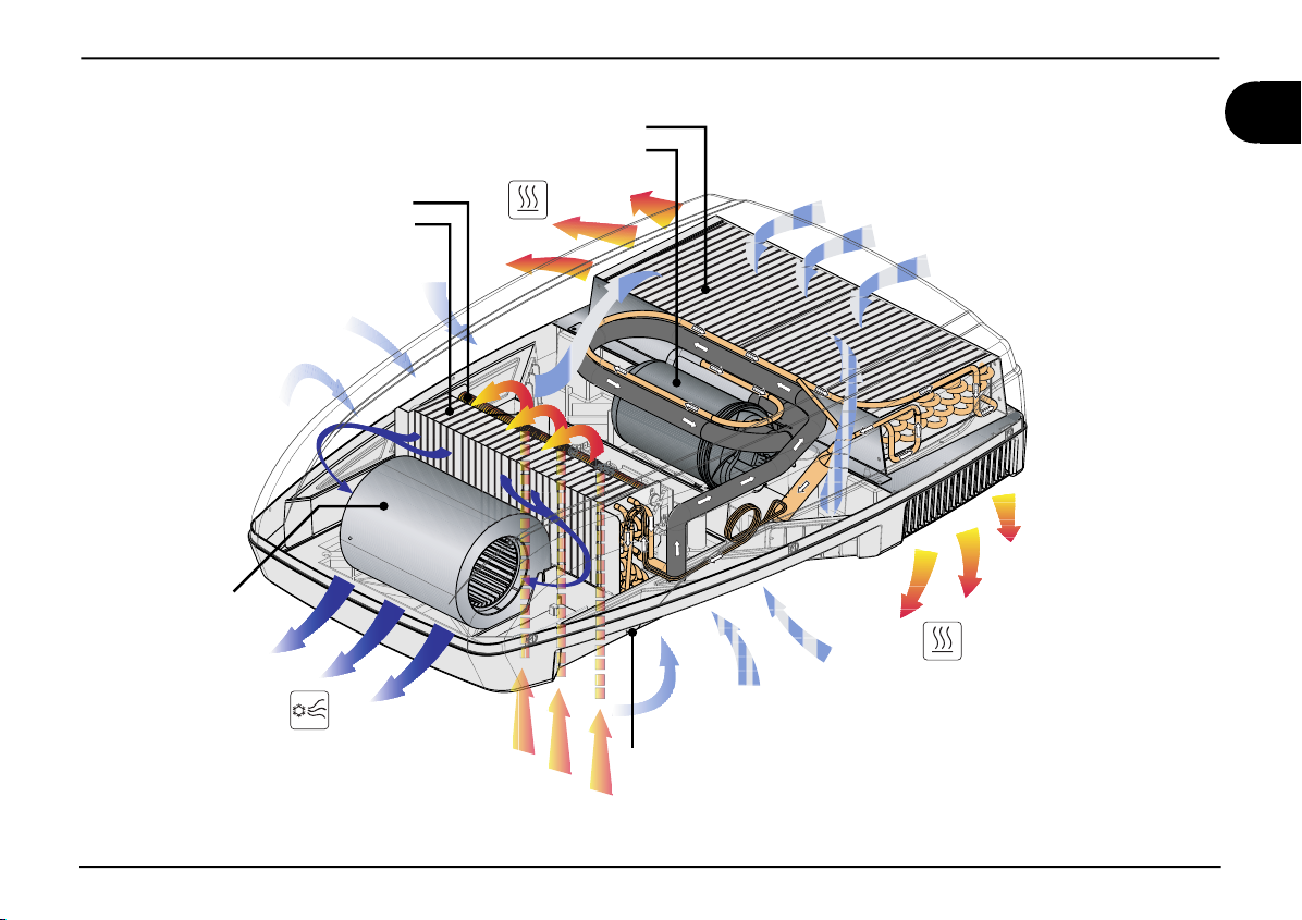
1.3. Description of the air conditioner
This air conditioner has been designed and manufactured to be installed
onto vehicles (i.e. camping-cars, caravans, motorhomes) to improve the
temperature conditions. It supplies fresh and dehumidifi ed air in summer
and warm air in winter without, in any case, replacing the heating system
of the vehicle. In both cases, temperature is set by the user.
Fresh air - Running
The system is inclusive of: compressor ( a ), condenser ( b ), evapora-
tor ( d ) and refrigerant gas under pressure. According to the physical
state of the refrigerant gas -i.e. liquid or gaseous, it heats or cools the
components where it passes through.
Fan ( c ) forces the internal air through the cooled evaporator from where
it comes out cooled down and dehumidifi ed.
This action, protracted over the time, reduces the temperature into
the vehicle.
Warm air - Running
Ambient air is forced by fan ( c ) into an electrical heating resistance
( e ) and then recirculated inside the vehicle.
B1600 - B2200
4
users ‘ instructions
Page 7
general informations 1
Fan (c)
conditioned air
drawn inside
Resistance (e)
Evaporator (d)
Air drawn in from outside
the vehicle
Condenser (b)
Compressor (a)
warm air
discharged
air recirculated
inside the vehicle
Air drawn in from outside
condensate draining
Air drawn in from outside
warm air
discharged
GB
users ‘ instructions
5
B1600 - B2200
Page 8
1 general informations
GB
1.4. How to use the air conditioner
The air conditioner performance can be improved by taking some
simple measures.
Improve the thermal insulation of the vehicle by closing any opening
•
and by covering any glassed surfaces with refl ecting curtains.
Avoid opening doors and windows unnecessarily.
•
Select the most suitable temperature and speed.
•
Properly direct the air fl aps.
•
To prevent troubles and minimise risks for people, take the following
precautions:
Do not obstruct the air inlets and outlets with cloths, paper or other
•
objects;
Do not introduce your hands or other objects into the openings;
•
Do not spray the air conditioner with water;
•
Keep fl ammable substances away from the air conditioner.
•
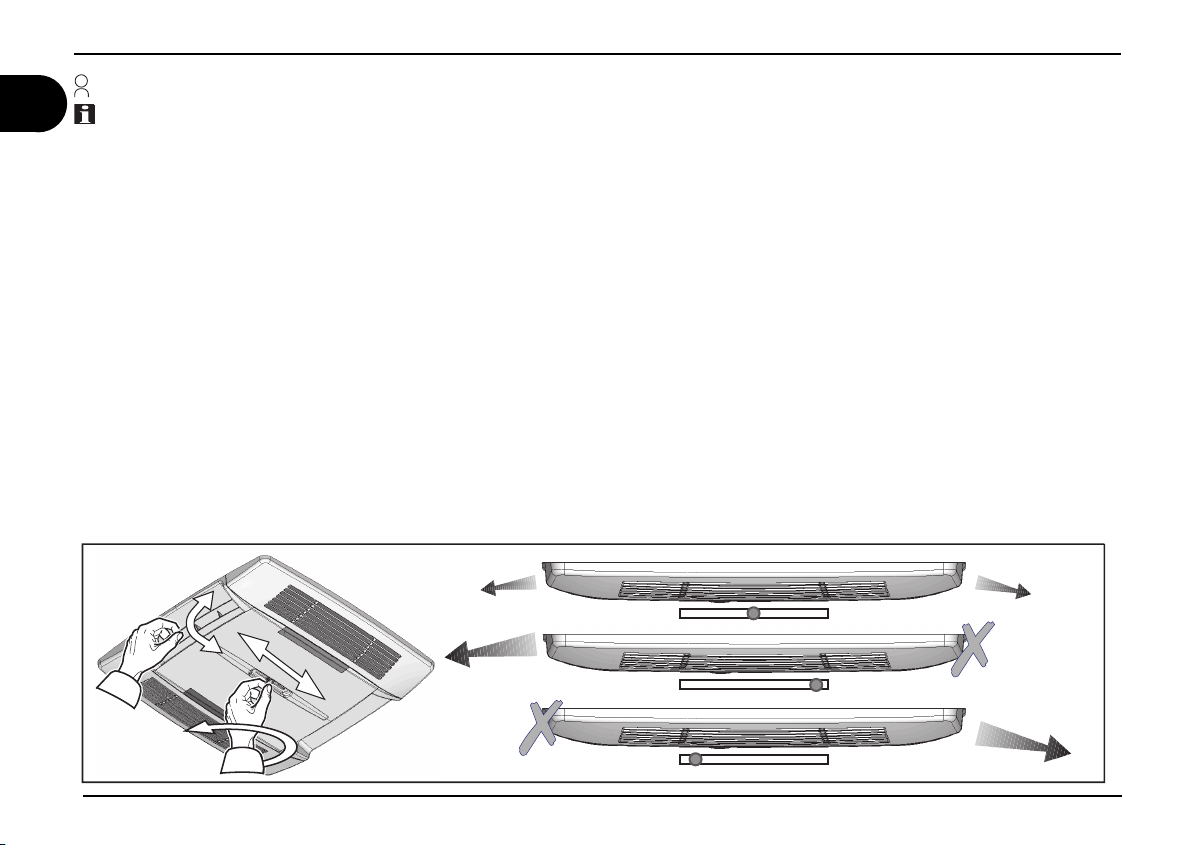
Adjusting the air direction
Position the air diffusing fl aps to direct the air to the desired position. In order to balance the airfl ow it’s necessary to rotate the center knob in
anticlockwise, to choose the wished position and then rotate clockwise.
B1600 - B2200
6
users ‘ instructions
Page 9
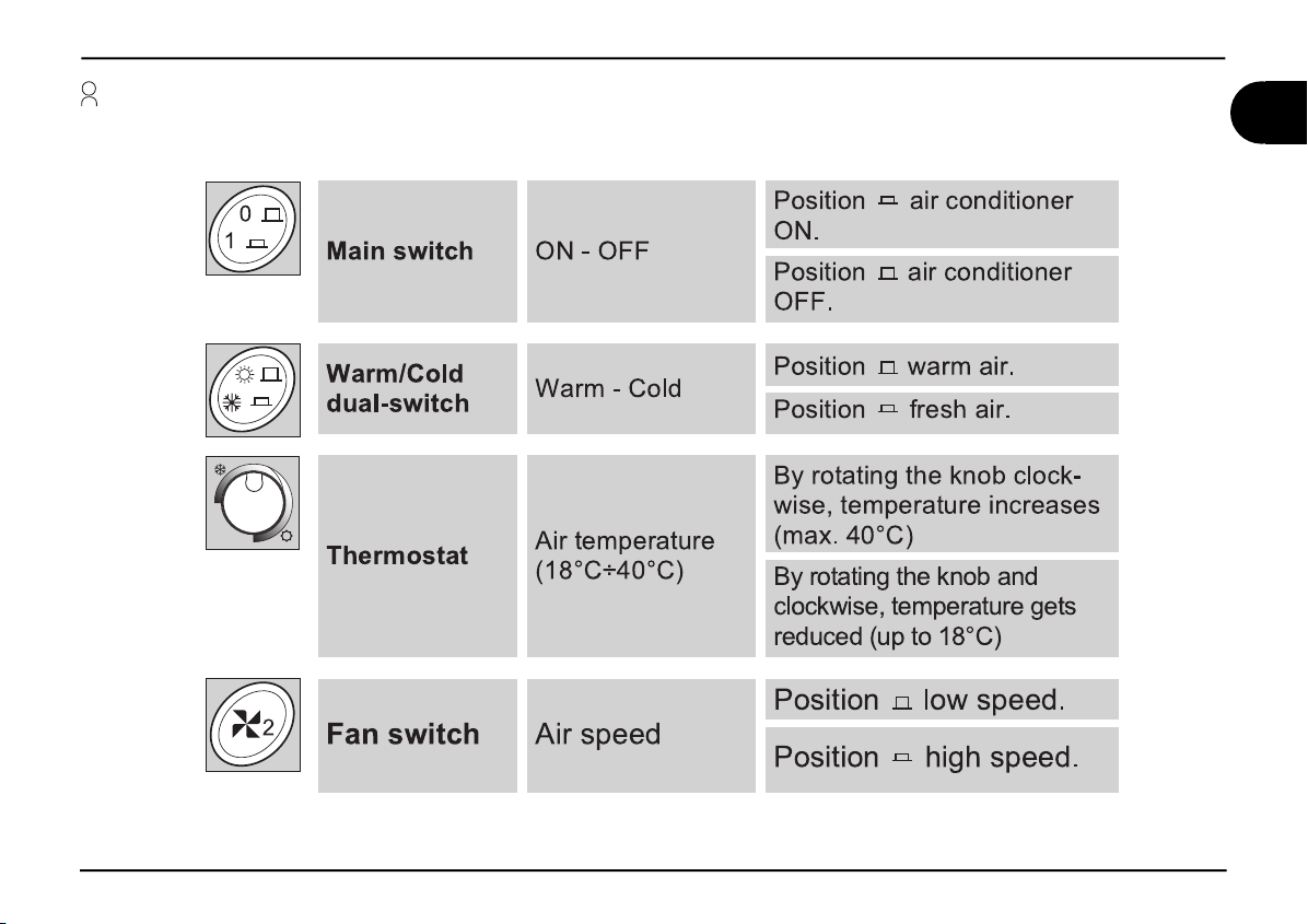
1.5.Description of the controls (B1600)
GB
*
* (only for models equipped with resistance)
users ‘ instructions
7
B1600 - B2200
Page 10

1 general informations
MODE
CLOCK
TIMER
SET
SLEEP
ROOM
F°/C°
LIGHT
IFEEL
F°/C°
LIGHT
ROOM
CLOCK
SET
TIMER
SLEEP
GB
1.5.Description of the controls (B2200)
Remote control (B2200)
REMOTE CONTROL
Operation Mode
Display Window
Timer
Clock Display
Set Point
Fan Speed Display
UP (+)
Down (-)
Clock
F°/C°
Light
Set
Room
Reset Button
* (only for models equipped with resistance) **(only for models equipped with light)
+
-
LIGHT
Press the ON/OFF button to start the airconditioner.
When it’s OFF all the symbols are OFF, except the
ON/OFF
clock and you can use the ROOM and the LIGHT
buttons.
Choose the temperature measurement unit between
Celsius (°C) or Fahrenheit (°F).
F°/C°
LIGHT
LIGHT**
Low Battery
If temperature is displayed this function is enabled.
Pressing the light key the light on the airconditioner diffuser is switched on (if equipped) .The light button works
also when the remote control is off.
Pressing this button the room symbol is displayed and
the local temperature is displayed instead the set point.
Pressing the Room button an other time the Room
0''
0/
Room
ROOM
Temperature
¡$
IFEEL
I Feel
Sleep
ON/OFF
Fan
CLOCK
Mode
Timer
SET
symbol disappear and the set point temperature is
displayed instead the local one.
This button works also when the remote control is off.
Pressing the “CLOCK” button for a time longer than 2
seconds, it is possible to modify the “TIME SETTING”,
managing the UP (+) button or the DOWN (-). Press
the “SET” button to confirm the modifications. After 15
seconds the new set is confirmed in any cases.
This button has two functions:
1) To confirm the TIME SETTING
2) To resend the actual operating setting
Press this button to set the time of automatic startup
TIMER
I FEEL
Sleep
I Feel
SLEEP
I FEEL
I FEEL
and/or shutdown.
Press this button to activate the SLEEP function. The
set point is adjusted automatically to increase comfort
when sleeping.
Every 10 minutes the operating set point is adjusted to
the temperature detected by the remote control.
The RESET button erases all the configuration parameters to default.
B1600 - B2200
8
users ‘ instructions
Page 11

general informations 1
30%%$
30%%$
30%%$
30%%$
MODE
MODE
MODE
AUTOMATIC MODE
¡$
AUTO
+
-
In this mode the fan button is disabled.
You can use the LIGHT** and ROOM button.
COOL / HEAT MODE
¡$ ¡$
Press the MODE button.
Set to “AUTO”
Choose the Set Point
(16°C - 31°C)
Press the MODE button.
Set to “COOL” or “HEAT”*
+
-
Choose the Set Point
(16°C - 31°C)
Choose the Fan Speed
You can use the LIGHT** and ROOM
FAN MODE
Press the MODE button.
Set to “FAN”
Choose the Fan Speed
You can use the LIGHT** and ROOM button.
Available Fan speeds (Cool/Heat*/Fan Mode)
Low battery
The low battery symbol will
appear in the display window
BATTERYCOMPARTMENT
ON BACK SIDE OF REMOTE
CONTROL
F
O
OFF
234
1
F
when the low battery condition
exists.
In this case after each
command, the “low voltage
symbol” flickers for 2 seconds.
In these 2 seconds the remote
control is not able to send other
commands.
Replace the batteries
2x1.5V AAA
GB
* (only for models equipped with resistance) - **(only for models equipped with light)
users ‘ instructions
9
B1600 - B2200
Page 12

GB
I FEEL
0/
0''
TIMER
Note: Every time the timer button is pressed, the display fl ashes for 15 seconds while waiting for the settings
to be modifi ed. Remember to set the clock to the correct time before using this function.
Setting the “ON” timer (automatic startup)
1) Press the TIMER button and the ON clock will start to fl ash.
2) Set the time required using the + and - buttons
3) Point the remote control at the receiver and press the “SET” button to confi rm
Setting the “OFF” timer (automatic shutdown)
1) Press the TIMER button twice and the OFF clock will start to fl ash.
2) Set the time required using the + and - buttons
3) Point the remote control at the receiver and press the “SET” button to confi rm
Setting the “ON” & “OFF” timer (automatic shutdown)
1) Press the TIMER button three times and the ON clock will start to fl ash while the OFF clock is visible.
2) Set the required ON time using the + and - buttons
3) Press the TIMER button and set the required OFF time using the + and - buttons
4) Point the remote control at the receiver and press the “SET” button to confi rm
SLEEP
0/
¡$
0''
1) Select the required temperature.
2) Press the SLEEP button
Note: The SLEEP function lowers the set temperature by 1° after one hour and by 2° after
two hours.
I FEEL
I FEEL
1) Press the I FEEL button to enable the function.
2) Position the remote control so that it is possible to send signals to the receiver.
3) The operating temperature is adjusted to the temperature detected by the remote control.
Note: The remote control must not be in an area that is much warmer or much cooler than
the normal room temperature (e.g.: exposed to direct sunlight or to the cold air coming from
the diffuser.)
B1600 - B2200
10
Configuring the remote control
For models with P/N:
CO2230XXXX
F
F
234
1
O
CO2231XXXX
For models with P/N:
F
F
O
234
1
CO2233XXXX
Note: Press RESET and reset the clock after
each modifi cation.
users ‘ instructions
Page 13

1.5.Description of the led state on the airdiffuser (B2200)
LED
LED State Description
Off Airconditioner off
GB
Orange
Green Airconditioner is running
Red (fi xed)
Red (1 fl ick) Anomaly - Malfunctioning of the E1 temperature probe (internal)
Red (2 fl icks) Anomaly - Malfunctioning of the E2 temperature probe (external)
users ‘ instructions
Airconditioner on StandBy (switch ON - aiconditioner is waiting for
a command)
Anomaly - 230V power supply missing (12V
is present)
11
B1600 - B2200
Page 14

1 general informations
GB
1.6. Technical data
Description Unit
Refrigerant gas (type/quantity) see data plate
Refrigerating yield Watt/h 1500* 2050*
Cooling consumption W 650 910
Heating capacity W 800 1200
Electrical rating V-Hz 230-50 230-50
Protection degree IP X4 X4
Conditioned air volume m
Max internal volume of the vehicle
(insulated walls)
Weight Kg 30 34
310
min 30
650
Model
B1600 B2200
3
/h 310 380
3
m
20 25
235
* according to EN 14511
B1600 - B2200
12
users ‘ instructions
Page 15

general informations 1
1.7. Ordinary maintenance
Petrol
Cleaning; periodically clean the air conditioner and remove dust with a dump cloth. When
necessary, use a mild detergent. Do not use petrol or solvents.
GB
Checks; regularly check the air con-
ditioner and make sure that the water
outlet holes are not clogged.
Filters cleaning (1): periodically carry out this operation; wash the fi lters with a detergent solution and allow to dry before refi tting.
Active carbon fi lter (2): It’s recomended to change the active carbon fi lters every year.
users ‘ instructions
13
B1600 - B2200
Page 16

2 Installation instructions
The air conditioner must be installed by skilled technicians. In addition to this requirement, the people making the unit installation must make sure
that the working conditions are safe for everybody concerned.
GB
2.1. Packaging, unpacking and handling
Always follow the instructions printed on the packaging.
B1600 - B2200
Remove the air conditioner from its packaging and made sure that
it is not damaged.
Never use the rear air openings to lift the air conditioner
from its packaging
Move the air conditioner to the installation site under safe conditions.
14
users ‘ instructions
Page 17

Installation instructions 2
2.2. Preparing the roof opening
To install the air conditioner, the roof shall have an opening of suitable sizes. It is possible to use an existing air inlet or make a new
one.
GB
According to the vehicle dimensions and depending on the air
conditioning needs, one or more units can be installed. The air
conditioner must be installed right in the middle with respect to the
vehicle Width and length.
Before installing the unit, make sure that the opening does not
interfere with the existing furnishing (lamps, wardrobes, doors,
curtains, etc.). This check allows for an easy mounting of the air
conditioner and a troublefree air circulation.
contact the vehicle manufacturer and make sure that the
roof structure can tolerate the static load and the stress transmitted vehicle, especially under running conditions. Sometimes vehicle manufacturers previously arrange areas for the
unit installation weakening and/or electric cable from being
cut.
users ‘ instructions
The air conditioner should preferably be installed on a
level plane. Maximum allowed inclination: 10°.
15
B1600 - B2200
Page 18

2 Installation instructions
GB
Danger of electrical hazards.
Turn all power sources off
Using an existing opening
Remove the skylight cover.
1.
Clean the installation opening all around
2.
by removing any adhesive residues.
Fill any existing screw hole or deformation
3.
with fi ller or silicone.
B1600 - B2200
16
users ‘ instructions
Page 19

Installation instructions 2
New installation opening
Using the printed cardboard template sup-
1.
plied with the unit, fi nd the position and dimensions of the new opening.
Drill the four corners.
2.
Cut by joining the previously made holes.
3.
If necessary, mount a reinforcing wooden
4.
frame.
GB
Drill a hole for the
supply cables
users ‘ instructions
17
B1600 - B2200
Page 20

2 Installation instructions
GB
2.3. Mounting the air conditioner
Set the air conditioner onto the roof opening. Never slide the air conditioner on
the roof, but lift when moving it.
Note: the conical pins under the base
must enter the roof openings.
Fix the air diffuser brackets to the base
using the 4 screws provided.
Always tighten to the recommended torque wrench setting. Do not overtighten!
B1600 - B2200
Mount the airdiffuser linking gaskets.
For correct thickness follow the table on
page 19.
18
Do the electrical connection as described
in paragraph 2.4.
users ‘ instructions
Page 21

Installation instructions 2
GB
Fix the cooling unit to the brackets using
the 4 screws provided.
THICKNESS OF THE ROOF THICKNESS OF THE GASKET
= 30 mm 10 mm
from 30 to 35 mm 15 mm
from 35 to 40 mm 20 mm
from 40 to 45 mm 25 mm
from 45 to 50 mm 30 mm
from 50 to 55 mm 35 mm
from 55 to 60 mm 40 mm
from 60 to 65 mm 45 mm
from 65 to 70 mm 50 mm
from 70 to 75 mm 55 mm
from 75 to 80 mm 60 mm
users ‘ instructions
Mount the fi lters in the order shown in
fi gure.
19
Mount the fi lters covers.
B1600 - B2200
Page 22

2 Installation instructions
GB
2.4. Electric connection
For the electric connections, always follow the national and local regulations
htg
neL
L
1
)m(
5,7<
,7>
5
noitcesssorC
2
m(
)m
5,1
5,2
Arrange a specifi c electric system
12-pole connector
from airconditioner
base
Red wire
Black wire
12-pole connector on
the electronic device
inside airdiffuser
12V DC
+ POLE BATTERY
- POLE BATTERY
B2200
230V 50Hz
Cyan wire
Brown wire
Green-Yellow wire
Cyan wire
Brown wire
Green-Yellow wire
2
Connect the wires to the air conditioner. Connect the electric system to a circuit supplying the required power
pusrewoprenoitidnocriA
suoiraV
sresu
esuF
x
ob
tiwsrevoegnah
C
hc
rotareneg/sniam
sniamylppuS
r
ewopcirtcelE
rotareneg
3
(see technical data) and fi tted with a good ground system.
ylp
B1600 - B2200
20
users ‘ instructions
Page 23

Troubleshooting, maintenance, recycling 3
3.1. Troubles, causes, solutions
Operations to be carried
out by the user
Operations to be carried out
by authorised personnel
CAUSA
the air conditioner does not cool suffi ciently
the air conditioner does not heat enough
no air circulation into the vehicle
water leaks into the vehicle
the air conditioner does not start
the air conditioner stops running
SOLUTION
temperature less than 18°C
temperature over 40°C
check the set point temperature
3.2. Extraordinary maintenance
For the best performance of your air conditioner, have your dealer/workshop clean it thoroughly before use:
thermal exchange batteries
1.
water outlet holes are properly cleaned.
2.
defective thermal protection
switch wrongly positioned
defective heating resistance
refrigerant gas is not enough
damaged compressor
3.3. Recycling
Regarding disposal and recycling, follow the national or local
regulations. To this end, address to the authorised environment
bodies.
thermal exchange batteries are dirty
defective internal fan
air fi lter is clogged
defective external fan
water outlet holes are clogged
damaged sealing gasket
no power supply
low power supply (less than 200V)
defective capacitor
defective thermal protection
GB
users ‘ instructions
21
B1600 - B2200
Page 24

Spare part list B1600 - B2200
GB
17
36
15
14
18
35
16
13
32
20
22
19
B2200
42
28
46
50
60
B1600
46
50
42
30
29
38
38
24
23
4
2
51
31
12
10
8
54
9
7
11
6
33
59
25
34
27
26
3
1
5
61
37
52
53
39
55
56
57
37
52
53
39
49
48
47
45
41
4
49
48
47
58
45
41
43
40
44
21
40
B1600 - B2200
22
Page 25

Spare part list B1600 - B2200
GB
N. DESCRPTION
1 PAN BASE
2 COVER
3 RIVETS TWO STAGE
4INSULATOR
5 GASKET
6 INSERTS
7 SUPPORT
8 SUPPORT
9 COMPRESSOR
10 CAPACITOR
11 VIBRATION DAMPER
12 COMPRESSOR WIRING
13 EVAPORATOR
14 GASKET
15 FAN
16* RESISTOR
17* BUSHING
18* SPRING
19 THERMAL SWITCH
20 OR GASKET
21 RIVETS
22 LABEL
23 CAPACITOR
N. DESCRPTION N. DESCRPTION
24 CAPACITOR
25 PLENUM
26 FAN SUPPORT
27 FAN
28 RELAY BOARD
29 CAPACITOR
30 CAPACITOR
31 CONDENSER
32 PIPE
33 PIPE
34 FILTER KIT
35 GASKET
36 HEAT INSULATOR BOX
37 AIR DIFFUSER BASE
38 AIR DIFFUSING FLAP
39 GRILLE
40 DEFLECTOR SLIDE
41 KNOB
42 COVER
43 RECEIVER BOARD
44 RECEIVER COVER
45 LABEL
46 FIXING BRACKET
47 GASKET
48 GASKET
49 GASKET
50 SCREW
51 LABEL
52 ACTIV CARBON FILTER
53 FILTER
54 WIRING
55 WIRING
56 SWITCH
57 THERMOSTAT
58 KNOB
59 GASKET
60 SUPPORT
61** LED BOARD
* (only for models equipped with resistance) - **(only for models equipped with light)
23
B1600 - B2200
Page 26

Page 27

B1600 wiring diagram
(Rev. 04)
V'
V'
V'
V'
V'
6
5
4
3
2
1
1
B1600 - B2200
WIRING DIAGRAMS
Page 28

0/0''
&$0/0.:
*/7&35&3
+
+
+
FAN1 CONDERNSER
."*/'64&
#"55&3:'64&
5&.1130#&
"694&3*"-
#"55&3:
$0/%'"/
$0/%'"/
&7"1'"/
3&4*4503
."*/
3&4*4503
$0.13&4403
3&.05&
+
3
3
5
53
+
$
$
$
$
$
$
$
$
$
$
+
+
+
+
+
+
2
3M
3M
3M
3M
3M
6
3
6
$
$
%;
+
+"
+#
$
$
')
'
'
')
N
EE
R
G-W
NW
K
O
EU
L
C
L
O
A
E
L
LB
RB
123
3
4
N
EE
K
R
C
A
G-W
L
B
O
L
L
E
Y
KN
I
P
5F5F
HCTI
HCTI
W
W
S
S
OM
OM
RE
RE
T
T
FAN2 CONDERNSER
4F4F
F
u
3F3F
xx Fuxx
*
**
Y
B
4
1
2
NW
EU
LB
O
RB
WIRING DIAGRAMS
D
E
R
*
*
*
*
1F1F
*
123
N
EERG-WOLLEY
1xO1
xO
*
*
*
2F2F
*
EUL
B
ROTSISE
R
R
T
T
AEH ROTSISE
AEH
$
*
* *
H
C
C
* *
T
T
I
I
$
WS O
WS O
M
M
RET H
RET
*
$
* *
3&4*4503
+#
$
*
*
2
x
O 2xO
5
COMPRESSOR
4
Y
3
2
B
R
B
1
&7"1'"/
$0/%'"/
+
$0/%'"/
+
$0.13&4403
+
3M
$
3M
$
3
3
."*/
3
+
123
MAIN FUSE F10AL250V
B2200 wiring diagram
O
N
LLE
EERG-W
KCALB
NWO
EUL
ORANGE
3&4*4503
+"
+
$
$
$
2
6
+
3&.05&
+
"694&3*"-
')
'
."*/'64&
5&.1130#&
+
53
3M
3M
3M
')
#"55&3:'64&
BATTERY
'
FUSE F2AL250V
%;
$
+
#"55&3:
+
&$0/0.:
+
0/0''
+
*/7&35&3
1
CKAL
B
2
3
EUL
B
4
LOIV
5
Y
E
8J
4C4C
6
D
ER
7
YARG
8
NAYC
9
01
W
TIH
6
1
2
$
$
$
$
B
NWORB
TE
WOLL
NEERG
E
2
TEMPERATURE
PROBE
EERG-WOLLEY
N
*
EUL
*
NWORB
T
*
V032
+ 12vdc BATTERY
ENIL - 1
FAN EVAPORATOR
- BATTERY
1
DNUORG - 3T
LARTUEN - 2T
CA
12
Led
board
OPTIONAL CONNECTION
TO SWITCH ON THE AIR
DIFFUSER LIGHT ALSO
WHEN THERE IS NO MAIN.
PLEASE USE THE
PROVIDED CONNECTOR
PLUGGED IN THE BOARD
AIR DIFFUSER
RED
BROWN
WHITE
YELLOW
BLAK
VIOLET
GRAY
2
xC
1
BLUE
CYAN
GREEN
Led
board
1234567891011
2
xC
1
2
xC
xJ
1
Led
board
2
Led
board
xC
xJ
1
xJ
3C3C
xJ
xJ
B1600 - B2200
2
Page 29

Page 30

DOMETIC
Via Virgilio, 3 - 47100 Forlì - Tel. 0543/754213 Fax.0543/756631
Cod. ST 087 R3
 Loading...