

Dometic 85090 DELUXE, 85093 DELUXE, 85094 DELUXE, 85096 ELITE, 85097 DELUXE INSTALLATION & OPERATING INSTRUCTIONS
...Page 1
Slide Topper Installation & Operating Instructions
RECORD THIS UNIT INFORMATION FOR
FUTURE REFERENCE:
Model Number
Serial Number
Date Purchased
USA
SERVICE OFFICE
Dometic Corporation
2320 Industrial Parkway
Elkhart, IN 46516
574-294-2511
CANADA
Dometic Corporation
46 Zatonski, Unit 3
Brantford, ON N3T 5L8
CANADA
519-720-9578
For Service Center
Assistance Call:
800-544-4881
®
SLIDE TOPPER
This manual must be read and understood before installation, adjustment, service, or maintenance is
performed. This unit must be installed by a qualified service technician. Modification of this product
can be extremely hazardous and
could result in personal injury or
property damage.
™
Lire et comprendre ce manuel avant de
procéder à l'installation, à des réglages,
de l'entretien ou des réparations.
L'installation de cet appareil doit être
effectuée par un réparateur qualifié.
Toute modification de cet appareil peut
être extrêmement dangereuse et
entraîner des blessures ou dommages
matériels.
INSTALLATION & OPERATING
INSTRUCTIONS
REVISION:
Form No. 3109384.101 1/06
(Replaces 3109384.093)
(French 3109626.097)
©2006 Dometic Corporation
LaGrange, IN 46761
Important:These instructions must stay with unit.
Owner read carefully.
1
MODELS
85090 DELUXE
85093 DELUXE
85094 DELUXE
85096 ELITE
85097 DELUXE
85098 ELITE
85099 DELUXE
85100 ELITE
85101 DELUXE
85102 ELITE
87096 ELITE
87097 DELUXE
85103 DELUXE
86096 ELITE
86097 DELUXE
86098 ELITE
86099 DELUXE
86100 ELITE
86101 DELUXE
86102 ELITE
86103 DELUXE
86111 DELUXE
Page 2
Slide Topper Installation & Operating Instructions
SAFETY INSTRUCTIONS
This manual has safety information and instructions to help users eliminate or reduce the risk of
accidents and injuries.
RECOGNIZE SAFETY INFORMATION
!
This is the safety-alert symbol. When you see this
symbol in this manual, be alert to the potential for
personal injury .
Follow recommended precautions and safe operating instructions.
A. GENERAL INSTRUCTIONS
These instructions must be read and understood before installation of this product. This
product must be installed by a Dometic Service Center or a qualified service technician.
Modification of this product can be extremely
hazardous and could result in personal injury
or property damage.
The A&E Slide Topper is designed to protect the top of an
RV's slide out room from weather and debris. It is not
waterproof, some drips, condensation, or wind blown precipitation can be present under the canopy.
Product features and specifications as described or illustrated are subject to change without notice. Installation
methods not described in this manual must have written
approval from Dometic Corporation.
Important: The slide topper cradle kits 3309526.XXX(X)
must be installed with all slide topper awnings over
lengths of 198". Installations of slide toppers over 198"
without the cradle kit 3309526.XXX(X) are not covered
by Dometic Warranty.
UNDERSTAND SIGNAL WORDS
A signal word , WARNING OR CAUTION is used
with the safety-alert symbol. They give the level of
risk for potential injury .
WARNING
!
ous situation which, if not avoided, could result in
death or serious injury .
CAUTION
!
ous situation which, if not avoided, may result in
minor or moderate injury .
CAUTION
symbol indicates, a potentially hazardous situation which, if not avoided, may result in property
damage.
Read and follow all safety information and instructions.
indicates a potentially hazard-
indicates a potentially hazard-
used without the safety alert
Note: Replace (X) with color code:
B = Polar White
H = Mende White
R = Champagne
S = Satin
U = Black
V = Gold
B. APPLICATION GUIDE
Models: 8XXXXXX.XXX (Elite) & (Deluxe)
1. DETERMINE SLIDE TOPPER LENGTH:
To determine the size of Slide Topper you require,
measure your room according to the FIG. 1 and FIG.
1A, then use the chart.
The Slide Topper will NOT work on rooms with a full
extension greater than 44 inches.
2
Page 3
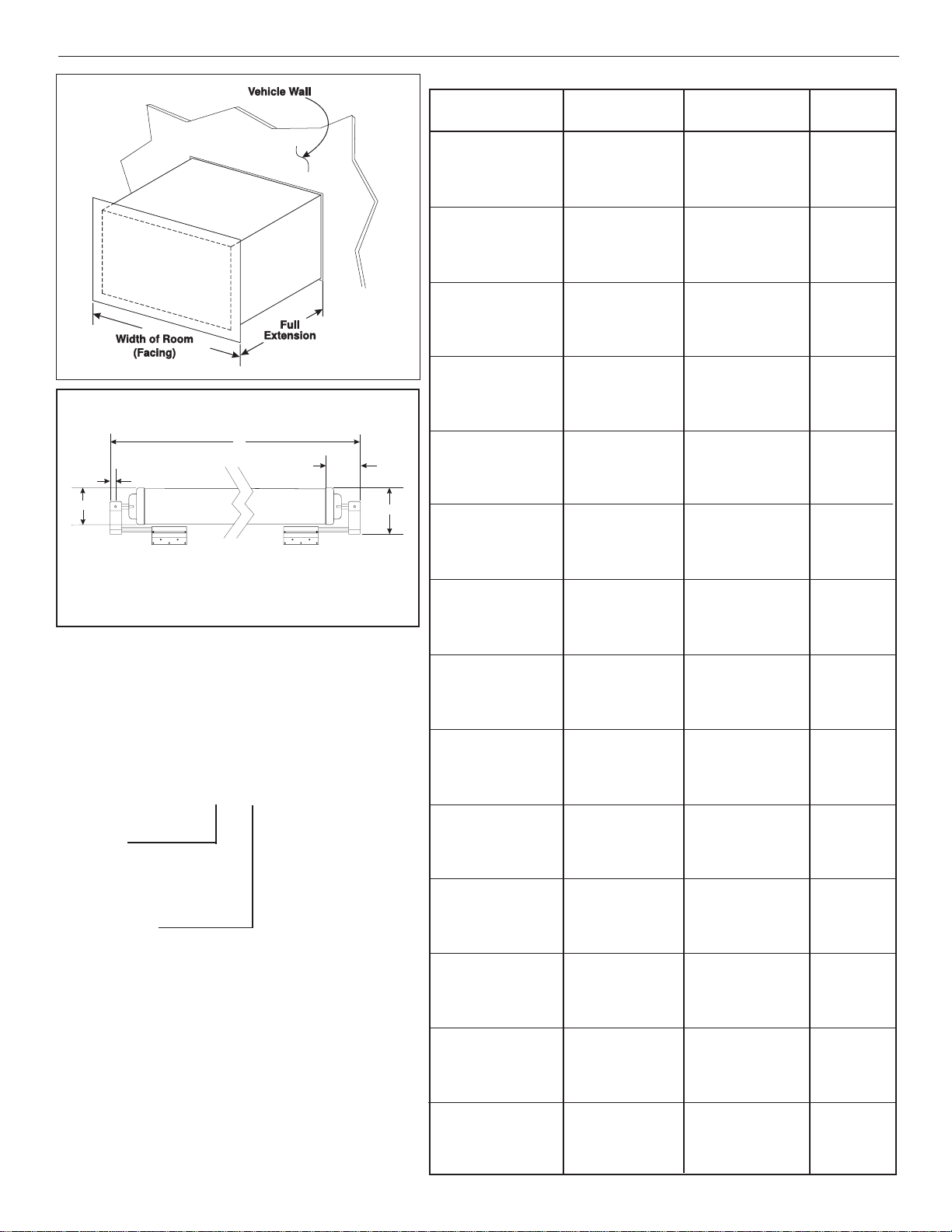
FIG. 1
FIG. 1A
A
E
C
D
A = Awning Length
B = 6-11/16"
D = 2-3/4"
E = 2-7/8"
C = 5/8"
2. DETERMINE BRACKETS REQUIRED FOR
THE SLIDE OUT:
3106992.(X)21(X) Bracket Kit
3106992.(X)39(X) Bracket Kit
3106992.(X)47(X) Bracket Kit
3106992.(X)70(X) Bracket Kit
3106992.(X)88(X) Bracket Kit
3106992.(X)96(X) Bracket Kit
Hex Bar Extension
Length:
0 = Standard 15-3/8"
1 = 18-5/8" ** See Note
Color Code:
B = Polar White
H = Mende White
R = Champagne
S = Satin
U = Black
V = Gold
Note : Use ONLY with 85XXXXX.060, 86XXXXX.060
**
and 87XXXXX.060 Models.
B
Slide Topper Installation & Operating Instructions
Size Chart
Awning Model
Suffix
8XXXXX.060 69-1/4” 50” 55-3/4” **See Note
8XXXXX.066 69-1/4” 56" 61-3/4" 66"
8XXXXX.016 74-1/2" 61-3/4" 66-1/2" 71-1/4"
8XXXXX.072 75-1/4" 62" 67-3/4" 72"
8XXXXX.011 79-1/2" 66-3/4" 72-1/2" 76-1/4"
8XXXXX.078 81-1/4" 68" 73-3/4" 78"
8XXXXX.017 84-1/4" 71" 76-3/4" 81"
8XXXXX.009 84-3/4" 71-3/4" 77-1/2" 81-1/2"
8XXXXX.084 87-1/4" 74" 79-3/4" 84"
8XXXXX.006 89-3/4" 76" 81-3/4" 86-1/2"
8XXXXX.090 93-1/4" 80" 85-3/4" 90"
8XXXXX.001 93-3/4" 80-1/2" 86-3/4" 90-1/2"
8XXXXX.092 95-1/4" 82" 87-3/4" 91-1/2"
8XXXXX.002 98-1/4" 81-3/4" 86-1/2" 95"
8XXXXX.096 99-1/4" 86" 91-3/4" 96"
8XXXXX.102 105-1/4" 92" 97-3/4" 102"
8XXXXX.019 106" 93-1/4" 99" 102-3/4”
8XXXXX.012 110-3/4" 97-1/2" 100-1/4" 107-1/2"
8XXXXX.108 111-1/4" 98" 103-3/4" 108"
8XXXXX.014 115-3/4" 102" 107-3/4" 112-1/2"
8XXXXX.114 117-1/4" 106-1/2" 109-3/4" 114"
8XXXXX.010 119-3/4" 108-1/2" 112-1/4" 116-1/2"
8XXXXX.020 122" 110-3/4" 116-1/2" 118-3/4"
8XXXXX.120 123-1/4" 112" 115-3/4" 120"
8XXXXX.007 127-3/4" 116-1/2" 122-1/4" 124-1/2"
8XXXXX.126 129-1/4" 118" 123-3/4" 126"
8XXXXX.132 135-1/4" 124" 129-3/4" 132"
8XXXXX.138 141-1/4" 130" 135-3/4" 138"
8XXXXX.005 142-1/4" 131" 136-3/4" 139"
8XXXXX.144 147-1/4" 136" 141-3/4" 144"
8XXXXX.021 150-1/4" 140" 145-3/4" 147"
8XXXXX.148 151-1/4" 141" 148-3/4" 148"
8XXXXX.150 152-3/4" 141-1/2" 147-1/4" 150"
8XXXXX.022 154" 142-3/4" 148-1/2" 151-1/4"
8XXXXX.152 154-3/4" 143-1/2" 149-1/4" 152"
8XXXXX.156 158-3/4" 147-1/2" 153-1/4" 156"
8XXXXX.013 159" 147-3/4" 153-3/4" 156-1/4"
8XXXXX.023 162-3/4" 151-1/2" 157-1/4" 160"
8XXXXX.162 164-3/4" 153-1/2" 159-3/4" 162"
8XXXXX.015 165-1/2" 154-1/4" 160" 162-3/4"
8XXXXX.003 168" 156-3/4" 162-1/2" 165-1/4"
8XXXXX.024 168-1/2" 157-1/2" 162-3/4" 165-3/4"
8XXXXX.166 168-3/4" 157-3/4" 163" 166"
8XXXXX.171 173-3/4" 162-1/2" 168-1/4" 171"
8XXXXX.025 174-1/2" 163-1/4" 169" 171-3/4"
8XXXXX.174 176-3/4" 165-1/2" 171-1/4" 174"
8XXXXX.177 179-3/4" 168-1/2" 174-1/4" 177"
8XXXXX.180 182-3/4" 171-1/2" 176-1/4" 180"
8XXXXX.026 184" 172-3/4" 178-1/2" 181-1/4"
8XXXXX.186 188-3/4" 177-1/4" 183" 186"
8XXXXX.192 194-3/4" 183-1/4" 189" 192"
8XXXXX.198 200-3/4" 189-1/4" 195" 198"
8XXXXX.204 206-3/4" 195-1/4" 201" 204"
8XXXXX.210 212-3/4" 201-1/4" 207" 210"
8XXXXX.216 218-3/4" 207-1/4" 213" 216"
8XXXXX.222 224-3/4" 213-1/4" 219" 222"
8XXXXX.228 230-3/4" 219-1/4" 225" 228
8XXXXX.234 236-3/4" 225-1/4" 231" 234"
8XXXXX.240 242-3/4" 231-1/4" 237" 240"
8XXXXX.246 248-3/4" 237-1/4" 243" 246"
8XXXXX.252 254-3/4" 243-1/4" 249" 252"
8XXXXX.258 260-3/4" 249-1/4" 255" 258"
8XXXXX.264 266-3/4" 255-1/4" 261" 264"
8XXXXX.270 272-3/4" 261-1/4" 267" 270"
8XXXXX.276 278-3/4" 267-1/4" 274" 276
8XXXXX.284 286-3/4" 274-1/4" 280" 284"
8XXXXX.290 292-3/4" 280-1/4" 286" 290"
8XXXXX.296 298-3/4" 286-1/4" 292" 296"
8XXXXX.300 302-3/4" 292-1/4" 298" 300"
Total Awning
Length (Dim. A)
Slide-Out Width
Min. - Max.
Awning
Length Req.
3
Page 4

Slide Topper Installation & Operating Instructions
Note: The greater the distance between the awning rail and the mounting bracket, the better water and debris will run off, however,
DO NOT exceed maximum distances shown or excess fabric will be exposed to catch wind.
Note: The 3106992.(X)21(X) mounting bracket kit is used when mounting the slide topper on a slide out room that is not flush to
the side of the coach. This kit is used when the slide out projects 1/4" to 1.0". See FIG. 2.
Slide Out
Projection
1/4” Min.
1” Max.
6” Min.
7” Max.
5.25 inch
Max.
Mounting Bracket
FIG. 2
Awning Rail
Slide-Out
Room
Flange or
Facing
0.74”
Side Flange
of Room
Mounting Bracket
(Kit # 3106992.X21X)
Top Flange
of Room
Mounting
Bracket
Position Bracket adjacent to
top and side flanges as shown.
FIG. 3
6” Min.
7” Max.
5.25 inch
Max.
Mounting Bracket
(Kit # 3106992.X39X, .X54X & .X62X)
Awning Rail
Slide-Out
Room
Flange or
Facing
1.24”
Side Flange
of Room
Mounting Bracket
Top Flange
of Room
Mounting
Bracket
Position Bracket adjacent to
top and side flanges as shown.
4
Page 5

FIG. 4
4” Min.
5” Max.
3.5” Max
Slide Topper Installation & Operating Instructions
Mounting Bracket
(Kit # 3106992.X47X, .X70X, 088X & 096X)
Awning Rail
Slide-Out
Room
Flange or
Facing
Top Flange
of Room
Z-Clip
1.24”
Mounting Bracket
Side Flange
of Room
When installing the A&E model Slide-Topper on vehicles
with extra large slide-out room flanges, it may be necessary to install the mounting bracket directly on the flange.
See FIG. 5 & 6.
FIG. 5
Position Bracket adjacent to
top and side flanges as shown.
Mounting
Bracket
The bracket must only be mounted on the flange where
there is sufficient backing material or framing behind the
flange.
FIG. 6
5
Page 6

Slide Topper Installation & Operating Instructions
OPTIONAL 3107940.003 SPACER KIT
Used when Slide-out flange has a large curve or is recessed
behind the main wall of vehicle.
SOME INSTALLATIONS MAY
REQUIRE USE OF SPACER KIT
3107940.003
FIG. 7
SPACER KIT SHOULD ALSO
BE USED WHEN SLIDE-OUT
ROOM WALL LIES BEHIND MAIN
WALL OF VEHICLE
3106992.039X
BRACKET
SHOWN
0.75”
1.24”
FIG. 8
SOME INSTALLATIONS MAY
REQUIRE USE OF SPACER KIT
3107940.003
SPACER KIT SHOULD ALSO
BE USED WHEN SLIDE-OUT
ROOM WALL LIES BEHIND MAIN
WALL OF VEHICLE
SIDE WALL WITH
RECESSED SLIDE-OUT
SHOWN
3106992.047X BRACKET
SHOWN
0.75”
1.24
PREPARATION: Unpack the awning and check the con-
INSTALLATION INSTRUCTIONS
tents against the following parts list:
(2) 308171.022 Pop Rivet (3/16" x 3/8")
*730099-(X) Awning Rail - Required
*3107216.008 Screw, Awning Rail, S 6-20 x 0.50" Sq Dr
**(1) 3106992.X21(X) Std Wall Brkt W/Anti-Billow
**(1) 3106992.X39(X) Offset Wall 60° Brkt W/Anti-Billow
**(1) 3106992.X47(X) Offset Wall 90° Brkt W/Anti-Billow
**(1) 3106692.X70(X) Offset Wall 90° Brkt W/Anti-Billow
(1)3106992.088(X) Offset Wall 90° W/Steel Hex Bars & Anti-Billow
(1)3106992.096(X) Offset Wall 45° W/Steel Hex Bars & Anti-Billow
*(2) 3309962.003(X) Bracket Spacer
NOTE: Replace (X) with color letter code
B = Polar White H = Mende
S = Satin R = Champagne
U = Black V = Gold
* Not included with all models
** Not included but one of the 3 options required.
WARNING
!
Severe injuries can result from a spinning
bracket. Do Not remove cotter pins until instructed to do so by these instructions.
INSTALL AWNING RAIL
1. See figure 2, 3, 4 and 9 to determine the correct location
for the awning rail.
ASSEMBLE EXTENSION
2. Rivet both extensions into the end brackets using the
two (308171.022) 3/16 x 3/8" pop rivets. Unwind ONLY
ONE wrap of the awning to allow easy insertion into the
awning rail. Slide wall brackets onto each hex extension.
See FIG. 10.
FIG. 9
Measure From
Bottom Of
Awning Rail
Mounting Distance
Measure From Inside
Edge Of Slide-Out
Room Frame.
Apply a sealant to the back edge of the awning rail to
prevent leaks, and install the awning rail using the
(3107216.008) #6 x 1/2" screws or equivalent. The rail
must be FIRMLY mounted to the vehicle.
Remove any drip shields or flashing which conflict with
the awning. The awning can be assembled and held in
location to check for conflicts with flashing.
MOUNTING DISTANCE
MNTG BRKT 3106992.X21X 6" - 7"
MNTG BRKT 3106992.X39X 6" - 7"
MNTG BRKT 3106992.X47X 4" - 5"
MNTG BRKT 3106992.X70X 6" - 7"
MNTG BRKT 3106992.X88X 4" - 5"
MNTG BRKT 3106992.X96X 6" - 7"
6
Page 7

FIG. 10
Slide Topper Installation & Operating Instructions
FIG. 11
Note: The Z-Clip brackets and oscar rivets (not supplied)
should be used when brackets are installed on laminated
walls and are required when using the 90° wall brackets. See
FIG. 12.
FIG. 12
MOUNT BRACKETS
3. Brackets must be mounted to vehicle framing. With the
room completely closed, lift the awning up to the top of
the slide out room. Insert the awning into the awning rail
and slide the awning into position. While one person
holds the awning in place, position the wall brackets at
the inside corners of the slide out room frame and use the
#10 X 1.0" screws ( supplied) to fasten them to the wall.
See FIG. 11.
WARNING
!
Personal injury and property damage hazard.
861 11 Series Slide T opper requires the use of
customer supplied #10 x 1-1/2" screws to fasten the brackets and supplied 1/2" spacer to
the wall. Do not use #10 x 1" screws or personal injury, damage to the Slide Topper, or
vehicle may occur .
Z-Clips
90° Bracket Shown
ALIGN FABRIC
4. Center the awning tube on the slide out room and then
lock it into position by driving two of the #10 x 0.75" selfdrilling screws (supplied) into the hex extension through
the holes in the middle and outside edge of each wall
bracket. (On some brackets, it is necessary to drill the
hole in the middle of the bracket.) (On .088X & .096X kits,
the holes must be predrilled using a #26 drill bit prior to
screw installation.) See figure 13.
FIG. 13
Install Screws
Z-Clips
CAUTION
Cotter pins must be removed before operating the slide-out room. Damages to the slide
topper and slide-out will occur , if cotter pin is
not removed before extending slide-out.
7
Page 8

Slide Topper Installation & Operating Instructions
Approx.
45°
Lock
Mechanism
Rotate
Tube
by
Hand
Vehicle
Wall
Vehicle WallVehicle Wall
Bumper in Rotated PositionBumper
in Rotated Position
Resting
Position is
Straight Up
Resting
Position
is
Straight
Up
Spacer
Edge
Protector
Edge
Protector
Slide-Out
Room Wall
Fully Closed
Slide-Out
Room
Wall
Fully
Closed
#10-12 x 0.75”
Screws
or
Oscar
Rivets
#10-12
x 0.75”
Screws
or
Oscar
Rivets
Secure Spacer
Extension
With
#10-12 x 0.75” Screw
Secure
Spacer
Extension
With
#10-12
x 0.75” Screw
REMOVE COTTER PINS
5. Straighten and then remove the cotter pins from both
sides of the awning. Check that the awning tube is free
to rotate by rotating it slightly by hand. If the tube is free
to rotate, open and close the room several times to
center the fabric in the roller tube and awning rail. Once
the fabric is centered, install a #6 x 0.63" screw through
the awning rail and fabric on both ends of the canopy so
it cannot shift from side to side. See figure 14.
Note: Models with slat assembly roller cover, place the #6
x 0.63" screw (supplied) through the awning rail 1/4" beyond
each end of the slat assembly.
FIG. 14
Remove both cotter pins before oper-
ating the slide out room
Vehicle
Wall
Spacer
Approx.
45°
Rotate
Tube
by Hand
Bumper
Lock
Mechanism
SELF DRILLING
SCREWS
FIG. 16
8. Attach locking mechanism to end cap using #10 selfdrilling screws (supplied). Use care when installing
screws not to move lock or scratch end cap.
9. Use the universal spacer to stop the bumper from
rotating past a 45° angle when the roller tube is rotated
by hand toward the wall. See figure 16. The universal
spacer will allow spacing from 5/16" to 1-1/2". See FIG.
17 & 18.
INSTALL LOCK MECHANISM
6. Position locking mechanism on end cap on leading end
of Slide Topper (end which is toward front of vehicle).
7. Position locking mechanism with bumper pointed straight
up. If either screw should happen to fall into an existing
opening in the end cap, rotate the bumper slightly away
from the wall before attaching. See figures 15 and 16.
FIG. 15
Side
Wall
90°
#10
Self-Drilling Screw
#10
Self-Drilling Screw
FIG. 17
8
Page 9

Slide Topper Installation & Operating Instructions
WARNING
!
CAUTION
FIG.
18
5/16" 1/2" 3/4" 1" 1-1/2"
10. Using 3105445.005 #10-12 x 0.75" screws, (supplied)
fasten spacer to the wall so that the bumper contacts the
spacer as shown in figure 17. If the vehicle has a
fiberglass wall, use Oscar rivets (not supplied) instead of
3105445.005 #10-12 x 0.75" screws.
11. Install edge protector (not supplied) on each end of slideout-room molding. See FIG. 17 & 19. Allow protector to
extend beyond edge of molding by 1/4" to 1/2".
Note: Not all installations will be able to use a Dometic edge
protector. If a Dometic edge protector is not used, a similar
type MUST be used. Units which are damaged by the slideout-room will NOT be covered under warranty.
Note: Oscar rivets and edge protectors are available as
separate items.
113008P10 Oscar Rivet = Package of 10
113008P100 Oscar Rivet = Package of 100
3308176.001 Edge Protector = Package of 10
3308176.019 Edge Protector = Package of 100
OPERATION
The Slide Out Topper will automatically open and close as
your slide out room opens and closes.
Because the awning is level, water may puddle on top of the
canopy. As the slide out room is closed and the awning rolls
up, these puddles will spill over the sides of the awning.
Do Not use your Slide Topper in snowing or
freezing-rain conditions. Such use will prevent the awning from closing, damage to the
awning and room will occur .
To prevent personal injury and damage. Do
Not operate your slide out room without first
checking that there are no people or objects
in the path of the room or the Slide Topper.
HELPFUL HINTS
FOR A WNING CARE
FIG. 19
• If the awning is wet when rolled up, as soon as
conditions allow, roll it out and let it dry before
rolling it up again. This will help prevent mildew
and staining.
• WHEN TO GET MORE HELP:
If malfunctions occur that cannot be corrected by
reviewing this Installation & Operation Instructions, contact a Dometic Service Center or a
qualified service technician. For Service Center
Assistance Call 800-544-4881.
9
 Loading...