

Dometic 57912.531, 57915.336, 57908.521, 57915.331, 57912.532 Installation Instructions Manual
...Page 1
RECORD THIS INFORMATION FOR FUTURE
REFERENCE:
Model Number
Serial Number
ADB Model Number
ADB Serial Number
Date Purchased
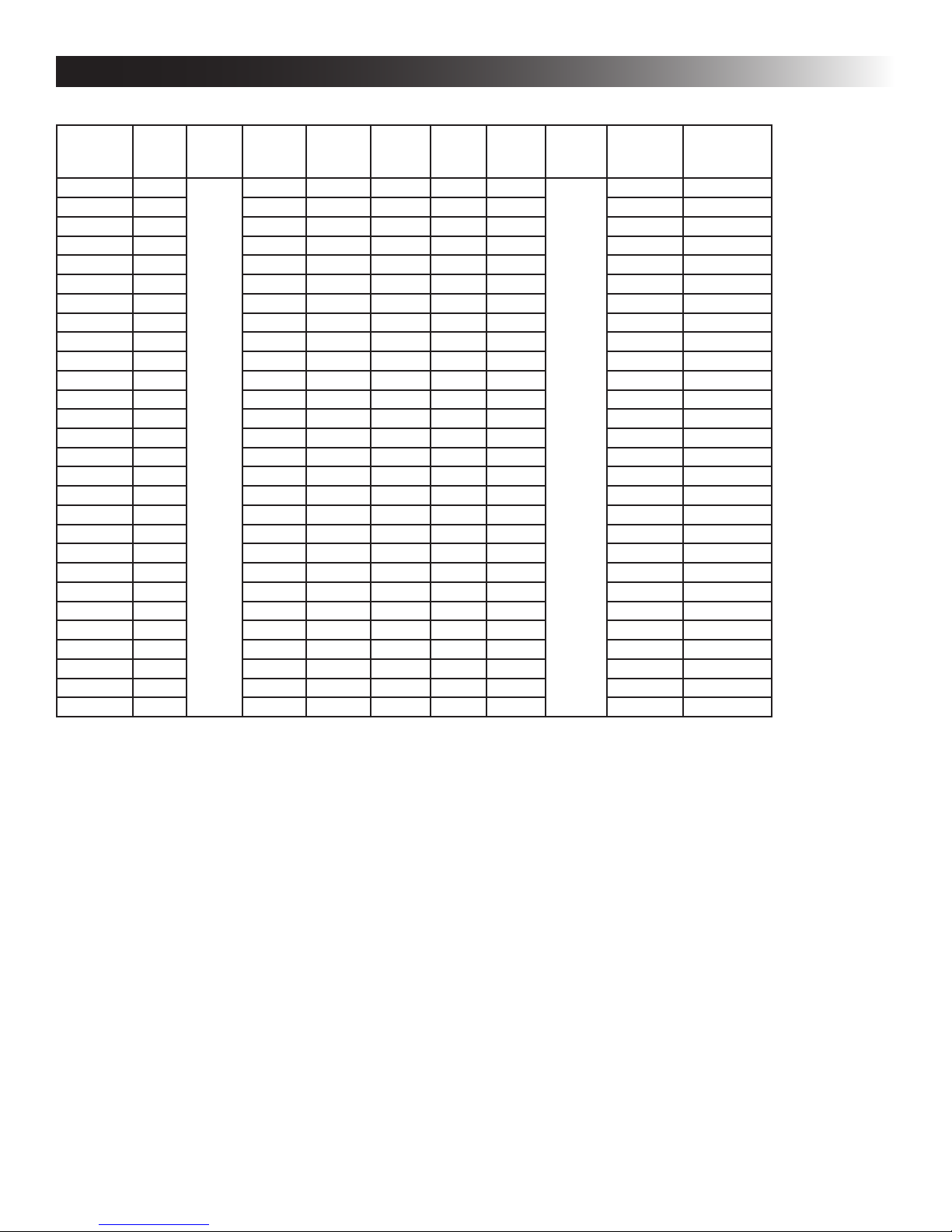
Roof Top Unit Used With 3105007.XXX or 3105935.XXX Air Distribution Box
Description Model Electronic Control Kit Thermostat Optional Indoor
Air Conditioner
LCD SZ Controls 57908
59712
57915
59516
59530
520300
520310
520315
520316
600312
600315
3316155.000 Thermostat Included With
Electronic Control Kit
Temperature
Sensor
N/A
INSTALLATION
INSTRUCTIONS
REVISION C
Form No. 3316570.000 6/18
French (3316571.000_C)
©2018 Dometic Corporation
LaGrange, IN 46761
This Unit is designed for OEM installation.
Read these instructions carefully. These
instructions MUST stay with this product.
USA
SERVICE OFFICE
Dometic Corporation
1120 North Main Street
Elkhart, IN 46514
SERVICE CENTER &
DEALER LOCATIONS
Please Visit:
www.eDometic.com
Page 2

INTRODUCTION
This air conditioner/heat pump (hereinafter referred to as “unit” or “product”) is designed and intended for installation on the
roof of a Recreational Vehicle (hereinafter referred to as RV) during the time it is manufactured.
Read these instructions and highlight the appropriate steps for your particular procedure before starting the installation.
This unit can be installed by one person with brief help from additional personnel. Use these instructions to ensure a properly
installed, and properly functioning product.
Dometic Corporation reserves the right to modify appearances and specications without notice.
TABLE OF CONTENTS
INTRODUCTION ..................................................................................................................................................................2
DOCUMENT SYMBOLS.......................................................................................................................................................2
IMPORTANT SAFETY INSTRUCTIONS ............................................................................................................................3
A. Recognize Safety Information ...................................................................................................................................3
B. Understand Signal Words ..........................................................................................................................................3
C. Supplemental Directives ............................................................................................................................................3
D. General Safety Messages .........................................................................................................................................3
SPECIFICATIONS ................................................................................................................................................................4
A. Table - Unit Data ........................................................................................................................................................4
B. Roof Requirements .................................................................................................................................................... 4
C. Table - Air Distribution Duct Sizing & Design .............................................................................................................5
INSTALLATION INSTRUCTIONS .......................................................................................................................................5
A. Choosing Proper Location For Unit ...........................................................................................................................5
B. Roof Preparation .......................................................................................................................................................6
C. Air Distribution Duct Sizing & Design ........................................................................................................................7
D. Wiring Requirements .................................................................................................................................................8
E. Choosing Thermostat Location ..................................................................................................................................8
F. Thermostat Installation .............................................................................................................................................9
G. Placing Unit On Roof ................................................................................................................................................. 9
H. Installation Preparation ............................................................................................................................................ 10
I. LCD SZ System Low Voltage Wire Connections .....................................................................................................12
J. Upgrading from Bi-Metal Thermostat to SZ LCD Thermostat .................................................................................12
K. Installing Return Air Cover .......................................................................................................................................13
GENERAL INFORMATION ................................................................................................................................................14
A. Frost Formation On Cooling Coil ............................................................................................................................. 14
B. Heat Gain ................................................................................................................................................................14
C. Condensation ..........................................................................................................................................................14
D. Air Distribution ......................................................................................................................................................... 14
WIRING DIAGRAMS ..........................................................................................................................................................15
A. Simple RV Wiring Diagram ......................................................................................................................................15
B. Unit Wiring Diagrams ............................................................................................................................................... 16
DOCUMENT SYMBOLS
Indicates additional information that is NOT related
to physical injury.
Indicates step-by-step instructions.
2
Page 3

IMPORTANT SAFETY INSTRUCTIONS
This manual has safety information and instructions to help
users eliminate or reduce the risk of accidents and injuries.
A. Recognize Safety Information
This is the safety alert symbol. It is used to
alert you to potential physical injury hazards.
Obey all safety messages that follow this
symbol to avoid possible injury or death.
B. Understand Signal Words
A signal word will identify safety messages and
property damage messages, and will indicate the
degree or level of hazard seriousness.
indicates a hazardous situation that,
if NOT avoided, could result in death or serious injury.
indicates a hazardous situation that,
if NOT avoided, could result in minor or moderate
injury.
is used to address practices NOT
related to physical injury.
C. Supplemental Directives
Read and follow all safety information and
instructions to avoid possible injury or death.
Read and understand these instructions before [installing / using / servicing / performing
maintenance on] this product.
Incorrect [installation / operation / servicing /
maintaining] of this product can lead to serious injury. Follow all instructions.
The installation MUST comply with all applicable local or national codes, including
the latest edition of the following standards:
U.S.A.
● ANSI/NFPA70, National Electrical Code
(NEC)
● ANSI/NFPA 1192, Recreational Vehicles
Code
CANADA
● CSA C22.1, Parts l & ll, Canadian Electri-
cal Code
● CSA Z240 RV Series, Recreational
Vehicles
D. General Safety Messages
Failure to obey the following warnings could result in death or serious injury:
● This product MUST be [installed / serviced] by a
qualied service technician.
● Do NOT modify this product in any way. Modica-
tion can be extremely hazardous.
● Do NOT add any devices or accessories to this
product except those specically authorized in
writing by Dometic Corporation.
3
Page 4
SPECIFICATIONS
A. Table - Unit Data
Model No. Nominal
57908.321 7,180 120 VAC
57908.521 7,100 6.6 34.0 2.5 5.8 17.0 20 Amp 2.5 kW / 4.0 kW
57912.531 11,000 8.0 53.0 2.5 5.8 18.5 20 Amp 2.5 kW / 4.0 kW
57912.532 11,000 12.1 59.0 2.5 5.8 16.5 20 Amp 3.5 kW / 5.0 kW
57915.331 13,500 11.4 58.0 2.5 5.8 15.5 20 Amp 3.5 kW / 5.0 kW
57915.336 13,500 12.1 59.0 2.5 5.8 16.5 20 Amp 3.5 kW / 5.0 kW
57915.531 13,500 12.1 59.0 2.5 5.8 16.5 20 Amp 3.5 kW / 5.0 kW
57915.536 13,500 12.1 59.0 2.5 5.8 16.5 20 Amp 3.5 kW / 5.0 kW
57915.541 13,500 11.3 62.0 2.5 5.8 16.0 20 Amp 3.5 kW / 5.0 kW
57915.546 13,500 11.3 62.0 2.5 5.8 16.0 20 Amp 3.5 kW / 5.0 kW
57915.741 13,500 12.0 58.0 2.5 5.8 15.5 20 Amp 3.5 kW / 5.0 kW
57915.746 13,500 12.0 58.0 2.5 5.8 15.5 20 Amp 3.5 kW / 5.0 kW
59516.331 15,000 11.5 50.0 2.5 5.8 29.0 20 Amp 3.5 kW / 5.0 kW
59516.336 15,000 12.7 60.0 2.0 5.6 29.0 20 Amp 3.5 kW / 5.0 kW
59516.531 15,000 11.5 50.0 2.5 5.8 26.5 20 Amp 3.5 kW / 5.0 kW
59516.536 15,000 11.5 50.0 2.5 5.8 29.0 20 Amp 3.5 kW / 5.0 kW
59516.731 15,000 13.3 62.0 2.0 5.6 29.0 20 Amp 3.5 kW / 5.0 kW
59530.532 N/A 8.0 53.0 2.5 5.8 18.5 15 Amp 3.5 kW / 5.0 kW
59530.536 N/A 7.8 53.0 2.0 5.6 19.0 15 Amp 3.5 kW / 5.0 kW
520310.501 9,000 7.8 49.0 3.0 8.5 20.0 20 Amp 2.5 kW / 4.0 kW
520315.501 13,500 10.3 62.0 3.0 8.5 16.5 20 Amp 3.5 kW / 5.0 kW
520315.506 13,500 10.3 62.0 3.0 8.5 16.5 20 Amp 3.5 kW / 5.0 kW
520316.501 15,000 13.2 79.0 2.8 7.6 30.0 20 Amp 3.5 kW / 5.0 kW
520316.506 15,000 13.2 79.0 2.8 7.6 30.0 20 Amp 3.5 kW / 5.0 kW
520300.501 N/A 7.8 49.0 3.0 8.5 20.0 15 Amp 2.5 kW / 4.0 kW
600312.331 11,000 9.5 53.0 3.5 10.0 17.0 20 Amp 2.5 kW / 4.0 kW
600315.331 13,500 12.4 60.0 3.5 10.0 15.2 20 Amp 3.5 kW / 5.0 kW
600315.336 13,500 12.4 60.0 3.5 10.0 15.2 20 Amp 3.5 kW / 5.0 kW
Capacity
(BTU HR)
Cooling
Electrical
Rating
60Hz. 1PH
Compressor
Rated Load
Amps
6.9 36.0 2.5 5.8 16.0 20 Amp 2.5 kW / 4.0 kW
Compressor
Locked
Rotor
Amps
Fan Motor
Rated Load
Amps
Fan Motor
Locked
Rotor
Amps
Refrigerant
R-410A
(Oz.)
Minimum
Wire Size*
AC Circuit
Protection
***Installer
Supplied
Minimum
Generator Size**
1 Unit / 2 Units
* For wire length over 24 ft., consult the National Electrical Code for proper sizing.
** Dometic Corporation gives GENERAL guidelines for generator requirements. These guidelines come from experiences
people have had in actual applications. When sizing the generator, the total power usage of your RV must be considered.
Keep in mind generators lose power at high altitudes and from lack of maintenance.
*** CIRCUIT PROTECTION: Time Delay Fuse or Circuit Breaker Required.
B. Roof Requirements
● A 14-1/4″ x 14-1/4″ (±1/8″) square opening (hereinafter referred to as “roof opening”) is required for installing this
unit. This opening is part of the return air system of the unit and MUST be nished in accordance with NFPA 1192.
● Roof construction with rafters/joists support frames on a minimum of 16 inch centers.
● Minimum of 2 inches and maximum of 5-1/2 inches distance between roof to ceiling of RV.
4
Page 5
SPECIFICATIONS
C. Table - Air Distribution Duct Sizing & Design
Air Distribution Duct Sizing & Design Chart
For Ducted Applications
Return Air Cover Model 3105007.XXX
Roof Cavity Depth 2 in - 2 1/2 in Max.
Duct Cross Section Area (inside) 21 in2 Min.
Duct Size
Depth
Width
Total Duct Length
Duct Length (short run)
Register Requirements per A/C Unit
Number Required
Free Air Area Per Register
Distance From Duct End
Distance From Elbow
Total System Static Air Pressure
Blower At High Speed, Filter &
Grill In Place
Note: Duct sizes listed are inside dimensions
3105935.XXX
1 1/2 in Min. - 2 1/2 in Max.
7 in Min. - 10 in Max.
15 ft Min. - 40 ft Max.
1/3 Min. Of Total Duct Length
4 Min. - 8 Max.
14 in2 Min.
5 in Min. - 8 in Max.
15 in
0.12 - 0.65 in W.C.
INSTALLATION INSTRUCTIONS
A. Choosing Proper Location For Unit
This unit is specically designed for installation on the roof
of an RV. When determining your cooling requirements, the
following should be considered:
● Size of RV;
● Window area (increases heat gain);
● Amount of insulation in walls and roof;
● Geographical location where the RV will be
used;
● Personal comfort level required.
1. For one unit installation: The unit should be
mounted slightly forward of center (front to back)
and centered from side to side.
2. For two unit installations: Install one unit 1/3 and
one unit 2/3’s from front of RV and centered from
side to side.
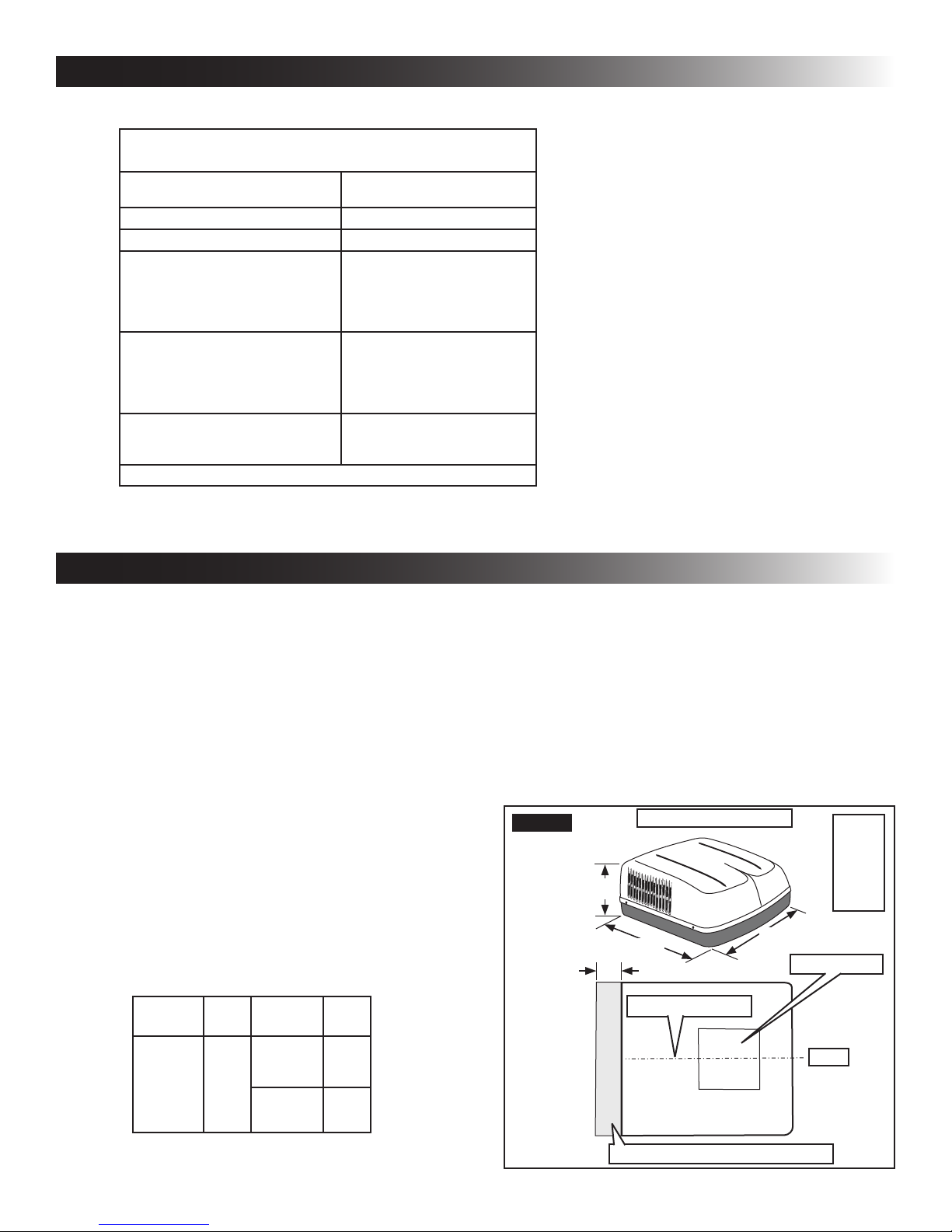
It is preferred that the unit be installed on a relatively at
and level roof section measured with the RV parked on a
level surface. See table below for maximum acceptable tilt.
Model
Number
57908
57912
57915
59516
59530
520300
Max
Tilt
15° 520310
Model
Number
520315
520316
600312
600316
Max
Tilt
15°
8°
FIG. 1
a. Check for obstructions in the area where
unit will be installed. See (FIG. 1), (FIG. 2)
& (FIG. 3).
b. Maintain structural integrity.
Otherwise damage to product and/or RV
could occur.
The roof must be designed to support 130
pounds when RV is in motion. Normally
a 200 lb. static load design will meet this
requirement.
13-1/8″
Dimensions Are Nominal
34-7/8″
18″
Center Line Of Unit
29-7/8″
Model
57908
57912
57915
57916
59530
Roof Opening
Front
3. After Location Has Been Selected:
Keep This Area Free Of Obstructions
5
Page 6

INSTALLATION INSTRUCTIONS
FIG. 2
13″
18″
FIG. 3
Dimensions Are Nominal
39-5/8″
Roof Opening
Center Line Of Unit
Keep This Area Free Of Obstructions
Dimensions Are Nominal
29-7/8″
Front
Model
520300
520310
520315
520316
FIG. 4
3/4″
17″
1-1/4″
Dimensions Are Nominal
17″
1-1/2″
1-1/2″
17″
17″
Roof
Opening
1-3/4″
Model
600312
600315
9-1/2″
40″
29″
12″
Center Line Of Unit
4″
Keep These Areas
Free Of Obstructions
4″
Roof Opening
Front
c. Check inside the RV for return air grille (here-
inafter referred to as “RAG”) obstructions
(i.e. door openings, room dividers, curtains,
ceiling xtures, etc). See (FIG. 4).
B. Roof Preparation
1. FIRE OR ELECTRICAL SHOCK
HAZARD. Make sure there are no obstacles
(wires, pipes, etc.) inside RV’s [roof / oor /
walls]. Shut OFF gas supply, disconnect 120
Vac power from RV, and disconnect positive (+)
12 Vdc terminal from supply battery BEFORE
drilling or cutting into RV. Failure to obey these
warnings could result in death or serious injury.
Opening Requirements - Before preparing
the ceiling opening, the type of system options MUST be decided upon. Read all of
the following instructions before beginning
the installation.
2. Carefully mark and cut the required roof opening.
See "B. Roof Requirements" on page (4).
3. Using the roof opening as a guide, cut the matching hole in the ceiling.
4. Maintain structural integrity. Otherwise damage to product and/or RV could occur.
NEVER create a low spot on RV
roof. Otherwise, water will pool and could cause
a leak.
6
Page 7

INSTALLATION INSTRUCTIONS
The opening created must be framed to provide
adequate support and prevent air from being
drawn from the roof cavity. Framing stock 407
mm or more in thickness must be used. Remember to provide an entrance hole for power supplies, indoor temperature sensor (if applicable),
thermostat communication cable, and furnace
wires (if applicable) at the front of the opening.
See (FIG. 5).
FIG. 5
Do Not Cut Roof
Structure Or
Rafters
19 mm Min.
3/4″ Min.
Good-Rafters
Supported By
Cross Beams
Frame Opening So It
Won't Collapse When
Good Location
Between Roof
Rafters
Bolting Down Unit
Leave Access For
Power Supply Wiring
15" Min. At
Front Of
Opening
C. Air Distribution Duct Sizing & Design
The installer of this system must design the air distribution
system for their particular application. Several requirements
must be met for the unit to operate properly. These requirements are as follows:
1. Make sure ductwork will NOT
bend or collapse during and after installation,
and that it is correctly insulated and sealed.
Otherwise, damage to roof structure and ceiling
could occur.
2. All discharge air ducts must be properly insulated to prevent condensation from forming on
their surfaces or adjacent surfaces during operation of unit. This insulation must be R-7 minimum. See (FIG. 6).
FIG. 6
TOP VIEW
(BACK OF RV)
Frame
Frame
Low Voltage Wires:
12 Vdc
Furnace
Roof
(TOWARD BACK OF RV
Duct
Roof Opening
DuctDuct
AC Power
Supply Wire
Frame
Indoor Temperature
Sensor Cable
SIDE VIEW
Roof Opening
Ceiling
Control Wires
Duct
Insulation
3. Ducts and their joints must be sealed to prevent
condensation from forming on adjacent surfaces
during operation of the unit.
4. Return air openings must have 40 square inches
minimum free area including the lter.
5. Return air to the unit must be ltered to prevent
dirt accumulation on unit cooling surface.
6. Air Distribution System Installation
a. Dometic Corporation recommends the basic
conguration shown in (FIG. 7), for installing
this system. We have found by testing, that
this conguration works best in most applications. It is the responsibility of the installer to
review each RV oor plan to determine the
following:
● Duct size
● Duct layout
● Register size
● Register location
● Thermostat location
● Indoor Temperature Sensor Location
These items must be determined in conjunction with the Air Distribution Duct System
Sizing & Design requirements. See "C. Table
- Air Distribution Duct Sizing & Design" on
page (5).
Alternate congurations and methods
may be used which will allow the unit
to operate properly; however, these
alternate congurations and methods
MUST be approved by Dometic Cor-
poration in writing. The following instructions are based upon the use of
RAG Kits 3105007.XXX & 3105935.
7
XXX.
Page 8

INSTALLATION INSTRUCTIONS
FIG. 7
Duct Size And Requirements For 3105007.XXX And 3105935.XXX RAG
D. Wiring Requirements
1. Route a copper, with ground, 120 Vac supply
wire from the time delay fuse or circuit breaker
box to the roof opening. Use a listed/certied
non metallic - sheathed single strand cable. See
"A. Table - Unit Data" on page (4).
a. This supply wire must be located in the front
portion of the roof opening.
b. The power MUST be on an appropriately
sized separate time delay fuse or circuit
breaker. See "A. Table - Unit Data" on page
(4).
c. Make sure that at least 15" of supply wire
extends into the roof opening. This ensures
an easy connection at the junction box.
d. Protect the wire where it passes into the
opening with approved method.
2. 12 volt DC supply comes from control box.
3. Thermostat Communication Cable
a. LCD SZ Thermostat
I. Route a 3 conductor communication ca-
ble, 18-22 AWG, from the roof opening
to the Liquid Crystal Display Single Zone
(hereinafter referred to a LCD SZ) thermostat mounting location. Make sure that
at least 15" of the wire extends into the
roof opening and 15" extends from the
wall at the thermostat mounting location.
See "E. Choosing Thermostat Location"
on page (8).
Register Required
Registers
4 Min - 8 Max.
(Per Unit)
14 Sq. In. Free
Area Per Register
4. If system includes a gas furnace, route two 1822 AWG thermostat wires from the furnace to
the roof opening of the unit that will control it.
If more than one furnace is to be used, route
the second set of thermostat wires to the second
unit. Make sure that at least 15" of wire extends
into the opening.
If converting from Bi-Metal Thermostat to
Single Zone Thermostat, see "I. LCD SZ
System Low Voltage Wire Connections"
on page (12) for wiring details.
E. Choosing Thermostat Location
1. LCD SZ system
a. The proper location of the thermostat is very
important to ensure that it will provide a comfortable RV temperature. Observe the following rules when selecting a location.
● Locate the thermostat 54" above the oor.
● Install the thermostat on a partition, not
on an outside wall.
● NEVER expose the thermostat to direct
heat from lamps, sun, or other heat producing items.
● Avoid locations close to doors that lead
outside, windows, or adjoining outside
walls.
● Avoid locations close to supply registers
and the air from them.
8
Page 9

INSTALLATION INSTRUCTIONS
F. Thermostat Installation
1. LCD SZ System
Wire colors listed for the communication
cable (3 conductor cable) match the wire
colors in the unit wire harness and the wire
harness at the LCD SZ electronic control
box. Available wire colors may vary.
a. Remove the cover from the LCD SZ thermo-
stat. Depress tab on bottom of thermostat
and separate it from the base.
b. Insert the previously run communication ca-
ble (3 conductor cable) through the hole in
the base assembly.
c. Cut back the outer cable shield approxi-
mately 3 inches and strip 1/4″ insulation from
each wire.
d. Mount the thermostat level on the wall using
the screws provided.
e. Make the following connections to the ther-
mostat. See (FIG. 20).
FIG. 8
G. Placing Unit On Roof
1. Remove the unit from the carton and discard
carton.
2. LIFTING HAZARD. Use proper
lifting technique and control when lifting product.
Failure to obey this caution could result in injury.
Place unit on the roof.
3. Do NOT slide unit. Otherwise,
damage to gasket (on bottom of unit) may occur,
and could cause a leak.
Lift and place the unit over the prepared opening using the gasket on the unit as a guide. See
(FIG. 9).
FIG. 9
Lift And Place
Front
12-
12+
COMMS
● Red/white wire to the 12V+ terminal
● Black wire to the 12V– terminal
● Orange wire to the "COMMS" terminal
f. Inspect all connections to make sure they
are tight and not touching any other terminals or wires.
g. Push the wires back through the base into
the wall. Place cover on the thermostat and
push until an audible click is heard.
Do Not Slide
Models May Vary In Appearance
4. Place the electronic control box kit (if applicable)
and the ADB kit inside the RV. These boxes contain mounting hardware for the unit and will be
used inside the RV.
This completes the outside work. Minor
adjustments can be done from inside the
RV if required.
9
Page 10

INSTALLATION INSTRUCTIONS
H. Installation Preparation
1. Check gasket alignment of the unit over the
roof opening and adjust if necessary. Unit may
be moved from below by slightly lifting. See
(FIG. 10).
FIG. 10
2. Remove return air cover and ceiling template
from carton. See (FIG. 11).
Center Unit From Below
Roof Gasket
FIG. 12
Gasket
5. Hold the ceiling template up to the roof opening.
Make sure the large plate faces the rear of the
RV. See (FIG. 13).
a. Start each mounting bolt through the ceiling
Control
Wires
120 Vac
Electrical
Cord
template and up into the unit base pan by
hand. Install wood screw in each end of the
ceiling template. This ensures a tight t of
the return air cover to ceiling. See (FIG. 13).
Power Supply
FIG. 11
Ceiling
Template
3. All models listed in this manual will use a four (4)
bolt pattern for installing the RAG kit.
4. Reach up into the return air opening and pull the
unit electric cord down for later connection. See
(FIG. 12).
Divider Plate
Return Air
Cover
Return Air
Grille
FIG. 13
Screws
Front Of Vehicle
b. Tighten mounting bolts to
correct torque specications. Overtightening could damage unit’s base pan or ceiling
template. Not enough torque will allow an inadequate roof seal, and could cause a leak.
Tighten all four (4) mounting bolts EVENLY
with in 40 to 50 inch pounds. (FIG. 13)
This will compress the roof gasket to
approximately 3/4″.
Roof
Gasket
Tighten To
Compress
Gasket To
3/4″
10
Page 11

INSTALLATION INSTRUCTIONS
6. Installation Of Divider Plate
a. Measure the ceiling to roof thickness:
● If distance is 2.0″ - 3-3/4″, remove perfo-
rated tab from divider plate. See (FIG. 14).
● If distance is 3-3/4″ - 5-1/2, remove no
tabs.
b. Remove the backing paper from double-
sided tape located on ceiling template. See
(FIG. 14).
FIG. 14
Paper Backing
2.00″ - 3.75″
d. With slight pressure push the divider plate
against the double-sided tape on the ceiling
template.
e. Locate the 1/8″ x 7″ x 18″ self-adhesive insu-
lation supplied with the RAG kit. Remove the
backing paper from the insulation and carefully stick onto the ceiling template divider
plate. See (FIG. 16).
FIG. 16
Place Insulation In Position
(Do Not Cover Unit Rating Plate)
Divider Plate
Foam Tape
FIG. 15
c. Divider plate MUST be in-
stalled correctly. Incorrect installation could
cause compressor to quick-cycle, and could
result in supply circuit overload and reduced
product performance.
The adhesive on the double-sided
tape is extremely sticky. Make sure
the divider plate is properly positioned
before pressing into place.
Place the divider plate up to bottom of the
unit base pan rmly. The foam tape on the divider plate must seal to bottom of base pan.
See (FIG. 15).
● Excess width is intended to seal the di-
vider plate to the sides of the roof opening. This is to help prevent cold air discharge from circulating into the unit return
air opening.
● If the insulation is too high, stick excess
height of the insulation to the unit base
pan. Do not cover up unit rating plate.
f. Place the electronic control box on the ceil-
ing template with the white 6 pin plug on the
curb side of the RV. Do NOT attach at this
time.
g. Plug the 6 pin connector into matching 6 pin
connector in the electronic control box. The
plug is polarized and will only t in one direction. See (FIG. 18).
h. Plug the supplied freeze control sensor and
the 4 wire harness into their matching connectors in the electronic control box.
i. Insert the freeze control sensor into the
evaporator coil ns approximately 1" above
the bottom of the coil ns and on the left side.
See (FIG. 17). Bend ns over sensor to se-
cure in place.
Push Divider Plate Firmly
Onto Base Pan
11
Page 12

INSTALLATION INSTRUCTIONS
FIG. 17
Freeze Control
Sensor
Remove
Hang Tag
Models May Vary
In Appearance
j. Attach electronic control box to the ceiling
template using the two (2) blunt self-tapping
screws provided in the electronic control box
kit. See (FIG. 18).
FIG. 18
Front
Route Up Through
Return Air Opening
Blunt SelfTapping Screw
I. LCD SZ System Low Voltage Wire
Connections
1. All Heat Pump Electronic Control Kit Systems
a. Plug the outdoor temperature sensor from
the unit into the white 2 pin matching connector in the electronic control box.
2. All LCD SZ Systems
a. Connect the previously run furnace thermo-
stat wires (if applicable) to the blue wires
protruding from the roof opening or to the
1/4″ connectors at the electronic control box
using the supplied 1/4″ insulated connectors.
The polarity of this connection does not mater.
FIG. 19
Connection
RV Wall
Splice
Blue
SZ LCD
or CTT
Thermostat
-12V Orange
Yellow
+12V Red
Control
Wires
(Connected
To T-Stat)
6 Pin Plug
From Unit
Low Voltage
Wiring From
Control Box
Electronic
Control Box
120VAC
Power
Supply
From RV
Freeze Sensor
Wire Harness
-12V
+12V
Furnace
AC Roof
Opening
Splice
Blue/White
-12V Black
3316300.000
Control Box
+12V Red
Green
J. Upgrading from Bi-Metal Thermostat to
SZ LCD Thermostat
1. Remove the existing thermostat from the wall.
2. Disconnect the four (4) wires coming from the air
conditioner (red, yellow, orange, blue).
3. Disconnect the two (2) wires coming from the
furnace (+12V, -12V).
Keep the red wires from the air
conditioner and furnace separate, to avoid confusion when connecting the thermostat. Connecting the wires incorrectly could result in property damage.
4. Refer to the wiring diagram (FIG. 19) and make
the connections as shown.
12
Page 13

INSTALLATION INSTRUCTIONS
K. Installing Return Air Cover
1. Remove the return air grille from the return air
cover.
2. Place the return air cover up to the ceiling template.
3. Install cover to template using six (6) supplied
#8 x 10 mm blunt point Phillips head screws.
4. Re-install lter return air grille into return air cov-
er. Align tabs with mating notches and snap into
place.
5. Install two (2) hole plugs into screw holes in
back of return air cover. See (FIG. 20).
FIG. 20
Return Air
Cover
Hole Plug
Return Air
Grille
13
Page 14

GENERAL INFORMATION
A. Frost Formation On Cooling Coil
Frost on a small portion of the coil is not un usual. Under
certain conditions, ice may form on the evaporator coil. This
is indicated by very cold output at very low air speed and
the icing can be seen through the air inlet hole with the lter
removed. If this should occur, inspect the lter and clean
if dirty. Make sure air vents are open and not obstructed.
Units have a greater tendency to frost when the outside
temperature is relatively low. This may be prevented by
ad justing the thermostat control knob to a warmer setting
(counter clockwise). Should frosting con tinue, operate on
any FAN ONLY setting until the cooling coil is free of frost;
then resume nor mal operation. If frost condition persist,
contact your local service center for assistance.
B. Heat Gain
The ability of this air conditioner to maintain the desired
inside temperature depends on the heat gain of the RV.
Some preventative measures taken by the occupants of the
RV can reduce the heat gain and improve the performance
of the air conditioner. During extremely high outdoor temperatures, the heat gain of the RV can may be reduced by:
1. Parking the RV in a shaded area
2. Using window shades (blinds and/or curtains)
3. Keeping windows and doors shut or minimizing
usage
4. Avoid the use of heat producing appliances
Operation on High Fan/Cooling mode will give optimum
or maximum eciency in high humidity or high outside
temperatures.
Starting the air conditioner early in the morning and giving
it a “head start” on the expected high outdoor ambient will
greatly improve its ability to maintain the desired indoor
temperature.
For a more permanent solution to high heat gain, accessories like Dometic outdoor patio and window awnings will
reduce heat gain by removing the direct sun. They also add
a nice area to enjoy company during the cool of the evening.
C. Condensation
The manufacturer of this unit will not be responsible for
damage caused by condensation forming on ceilings,
windows, or other surfaces. Air contains water vapor which
condenses when temperature of a surface is below Dew
point. During normal operation this unit is designed to
remove a certain amount of moisture from the air, depending on the size of the space being conditioned. Keeping
doors and windows closed when this air conditioner is in
operation will greatly reduce the chance of condensation
forming on interior surfaces.
D. Air Distribution
Each A/C unit operating in cool mode, must have a minimum of 2 distribution vents, or the quick cool vent and one
vent open, to avoid the risk of freezing coils and improper
function.
14
Page 15

WIRING DIAGRAMS
A. Simple RV Wiring Diagram
FIG. 21
(OPTIONAL)
15
Page 16

579, 590, 595, 4579, 4590,600,640,520, 540
WIRING DIAGRAMS
B. Unit Wiring Diagrams
1. 57908, 57912, 57915, 59516, 59530, 520300, 520310, 520315, 520316, 600312 & 600315
2. LCD SZ Controls
3316453.000_A
A/C
CONNECTION
FURNACE
FURNACE
COMM TSTAT
12V - TSTAT
12V + TSTAT
1
2
3
4
GRN/YEL
56WHT
4
RED
3
N/C
BLK
2
1
BLU
BL/WT
BL/WT
GRN
BLK
RED
NO
J4
FAN HI
J3
FAN LO
COM
J2
FURNACE
J1
FURNACE
P1
314
115 VAC,
60 HZ, 1Φ
USE COPPER
CONDUCTORS
ONLY
FREEZE
SENSOR
21
P2
J5
2
FOR USE WITH AIR CONDITIONER:
FOR A/C WITHOUT HEAT STRIP OR
C
PART No. 3316300.000
SERIAL No.
HEAT PUMP OPTION
PASSED
DIELECTRIC
FIELD WIRING
FACTORY WIRING
R
154624
US
54-132704-A
16
 Loading...