

Dometic 489516P series, 489516A series, 489516P70X, 489516P71X, 489516A71X Installation & Operating Instruction
...Page 1
RECORD THIS INFORMATION FOR FUTURE
REFERENCE:
Model Number
Serial Number
ADB Model Number
ADB Serial Number
Date Purchased
DuraSea Roof Top Air Conditioner
Roof Top Unit
Description Model Use With Air Distribution Box (not included)
Model Control
Air Conditioner 489516P
489516A
3314861.000 Integral Mechanical
INSTRUCTIONS
INSTALLATION & OPERATING
REVISION B
Form No. 3315430.000 08/16
(French 3315824.000_B)
©2016 Dometic Corporation
LaGrange, IN 46761
USA
SERVICE OFFICE
Dometic Corporation
1120 North Main Street
Elkhart, IN 46514
Read these instructions carefully. These
instructions MUST stay with this product.
CANADA
Dometic Corporation
46 Zatonski, Unit 3
Brantford, ON N3T 5L8
CANADA
SERVICE CENTER &
DEALER LOCATIONS
Please Visit:
www.eDometic.com
Page 2

INTRODUCTION
This air conditioner (hereinafter referred to as “unit” or “product”) is designed and intended for installation on the roof of a
boat during or after the time the vessel is manufactured.
This unit can be installed by one person with brief help from additional personnel. Use these instructions to ensure a properly
installed, and properly functioning product.
Dometic Corporation reserves the right to modify appearances and specications without notice.
TABLE OF CONTENTS
INTRODUCTION .................................................................................................................................................................... 2
IMPORTANT SAFETY INSTRUCTIONS ................................................................................................................................3
A. Recognize Safety Information ...................................................................................................................................3
B. Understand Signal Words ..........................................................................................................................................3
C. Supplemental Directives ............................................................................................................................................3
D. General Safety Messages .........................................................................................................................................3
DOCUMENT SYMBOLS ........................................................................................................................................................3
SPECIFICATIONS .................................................................................................................................................................. 4
A. Table - Unit Data ........................................................................................................................................................4
B. Roof Requirements .................................................................................................................................................... 4
INSTALLATION INSTRUCTIONS ..........................................................................................................................................5
A. Choosing Proper Location For Unit ...........................................................................................................................5
B. Roof Preparation .......................................................................................................................................................5
C. Wiring Requirements .................................................................................................................................................6
D. Placing Unit On Roof .................................................................................................................................................6
E. Installing Unit ............................................................................................................................................................. 7
F. Wiring System ...........................................................................................................................................................9
G. Installing ADB ............................................................................................................................................................9
OPERATING INSTRUCTIONS ............................................................................................................................................. 11
A. Controls ................................................................................................................................................................... 11
B. "OFF" Position ( ) .................................................................................................................................................. 11
C. Cooling Operation (Blue Graphic) ...........................................................................................................................11
D. Heating Operation (With Electric Heater Option Installed). .....................................................................................11
E. Fan Operation (Black Graphic) ................................................................................................................................ 11
F. Center Air Discharge ............................................................................................................................................... 11
MAINTENANCE ...................................................................................................................................................................12
A. Air Filter ...................................................................................................................................................................12
B. ADB Housing ........................................................................................................................................................... 12
C. Fan Motor ................................................................................................................................................................12
GENERAL INFORMATION ...................................................................................................................................................12
A. Frost Formation On Cooling Coil ............................................................................................................................. 12
B. Heat Gain ................................................................................................................................................................12
C. Condensation ..........................................................................................................................................................12
SERVICE - UNIT DOES NOT OPERATE ............................................................................................................................13
WIRING DIAGRAMS ............................................................................................................................................................ 13
A. Unit Wiring Diagram ................................................................................................................................................13
B. ADB Wiring Diagram ...............................................................................................................................................13
OWNER'S LIMITED WARRANTY ........................................................................................................................................14
A. What's Covered .......................................................................................................................................................14
B. What's Not Covered ................................................................................................................................................14
C. Coverage Period ......................................................................................................................................................15
D. Getting Service ........................................................................................................................................................15
E. Table Of Warranty Periods.......................................................................................................................................16
2
Page 3

IMPORTANT SAFETY INSTRUCTIONS
This manual has safety information and instructions to help
users eliminate or reduce the risk of accidents and injuries.
A. Recognize Safety Information
This is the safety alert symbol. It is used to
alert you to potential physical injury hazards.
Obey all safety messages that follow this
symbol to avoid possible injury or death.
B. Understand Signal Words
A signal word will identify safety messages and
property damage messages, and will indicate the
degree or level of hazard seriousness.
indicates a hazardous situation that,
if NOT avoided, could result in death or serious injury.
indicates a hazardous situation that,
if NOT avoided, could result in minor or moderate
injury.
is used to address practices NOT
related to physical injury.
C. Supplemental Directives
Read and follow all safety information and
instructions to avoid possible injury or death.
Read and understand these instructions before [installing / using / servicing / performing
maintenance on] this product.
Incorrect [installation / operation / servicing /
maintaining] of this product can lead to serious injury. Follow all instructions.
The installation MUST comply with all applicable ABYC, local or national codes,
including the latest edition of the following
standards:
U.S.A.
● ANSI/NFPA70, National Electrical Code
(NEC)
CANADA
● CSA C22.1, Parts l & ll, Canadian Electri-
cal Code
DOCUMENT SYMBOLS
Indicates additional information that is NOT related
to physical injury.
D. General Safety Messages
Failure to obey the following warnings could result in death or serious injury:
● This product MUST be [installed / serviced] by a
qualied service technician.
● Do NOT modify this product in any way. Modica-
tion can be extremely hazardous.
● Do NOT add any devices or accessories to this
product except those specically authorized in
writing by Dometic Corporation.
Indicates step-by-step instructions.
3
Page 4

SPECIFICATIONS
A. Table - Unit Data
Model No. Nominal
489516P70X 15,000 120 Vac
489516P71X 15,000 13.3 70.0 2.5 5.8 27.5 20 Amp 3.5 kW / 5.0 kW
489516A71X 15,000 13.3 70.0 2.5 5.8 27.5 20 Amp 3.5 kW / 5.0 kW
Capacity
(BTU HR)
Cooling
Electrical
Rating
60 Hz 1 ph
Compressor
Rated Load
Compressor
Amps
13.3 66.0 2.5 5.8 27.5 12 AWG
Locked
Rotor
Amps
Fan Motor
Rated Load
Amps
Fan Motor
Locked
Rotor
Amps
Refrigerant
R-410A
(oz)
Minimum
Wire Size*
Copper
Up to 24'
AC Circuit
Protection
***Installer
Supplied
20 Amp 3.5 kW / 5.0 kW
Minimum
Generator
Size**
1 Unit / 2 Units
* For wire length over 24 ft., consult the National Electrical Code for proper sizing.
** Dometic Marine gives GENERAL guidelines for generator requirements. To reduce start-up power draw by up to 65%,
consider installing a Dometic SmartStart.
*** CIRCUIT PROTECTION: Time Delay Fuse or Circuit Breaker Required.
B. Roof Requirements
● A 14-1/4″ x 14-1/4″ (±1/8″) square opening (hereinafter referred to as “roof opening”) is required for installing this
unit. This opening is part of the return air system of the unit and MUST be nished in accordance with NFPA 1192.
● If applicable: Roof construction with rafters/joists support frames on a minimum of 16 inch centers.
● Minimum of 1.5 inches and maximum of 6 inches distance between roof to ceiling.
4
Page 5
INSTALLATION INSTRUCTIONS
A. Choosing Proper Location For Unit
This unit is specically designed for installation on the roof
of a boat. Mount only with front of unit facing the bow (the
vented end should face aft). See "FIG. 4" on page (6).
When determining your cooling requirements, the following
should be considered:
● Size of boat;
● Window area (increases heat gain);
● Amount of insulation in walls and roof;
● Geographical location where boat will be used;
● Personal comfort level required.
It is preferred that the unit be installed on a relatively at
and level roof section. See table below for maximum acceptable tilt.
Model
Number
489516P
489516A
1. After Location Has Been Selected:
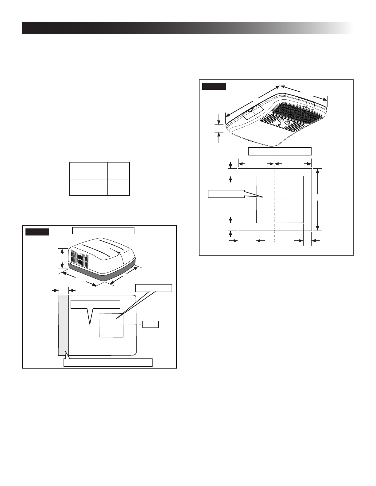
a. Check for obstructions in the area where unit
will be installed. See (FIG. 1).
FIG. 1
Dimensions Are Nominal
Max
Tilt
15°
FIG. 2
2-5/8″
3-7/16″
Roof Opening
3-7/16″
6″
c. Check inside the boat's cabin for air distri-
bution box (hereinafter referred to as "ADB")
obstructions (i.e. space for doors to open,
room dividers, curtains, ceiling xtures, etc.).
See (FIG. 2).
23-1/8″
Dimensions Are Nominal
11-9/16″
11-9/16″
21-1/8″
21-1/8″
2-7/8″
13-1/8″
34-7/8″
18″
Center Line Of Unit
Keep This Area Free Of Obstructions
29-7/8″
Roof Opening
Front
b. Maintain structural integrity.
Otherwise damage to product and/or boat
could occur.
The roof must be designed to support 130
pounds when the boat is in motion. Normally a 200 lb. static load design will meet this
requirement.
B. Roof Preparation
1. FIRE OR ELECTRICAL SHOCK
HAZARD. Verify there are no obstacles inside
boat’s roof and/or walls (wires, pipes, etc.). Shut
OFF gas supply, disconnect 120 Vac power from
boat and disconnect positive (+) 12 Vdc terminal
from supply battery BEFORE drilling or cutting
into boat. Failure to obey these warnings could
result in death or serious injury.
Opening Requirements - Before preparing the ceiling opening, read all of the following instructions before beginning the
installation.
2. Carefully mark and cut the required roof opening.
See "B. Roof Requirements" on page (4).
3. Maintain structural integrity. Otherwise damage to product and/or boat could occur.
NEVER create a low spot on boat
roof. Otherwise, water will pool and could cause
a leak.
5
Page 6

INSTALLATION INSTRUCTIONS
Using the roof opening as a guide, cut the matching hole in the ceiling.
The opening created must be framed to provide
adequate support and prevent air from being
drawn from the roof cavity. Framing stock 3/4″ or
more in thickness must be used. Remember to
provide an entrance hole for power supplies at
the front of the opening. See (FIG. 3).
FIG. 3
Do Not Cut Roof
Structure Or
Rafters
3/4″ Min.
Good-Rafters
Supported By
Cross Beams
Frame Opening So It
Won't Collapse When
Bolting Down Unit
Good Location
Between Roof
Rafters
D. Placing Unit On Roof
1. Remove the unit from the carton and discard
carton.
2. LIFTING HAZARD. Use proper
lifting technique and control when lifting product.
Failure to obey this caution could result in injury.
Place unit on the roof.
3. Do NOT slide unit. Otherwise,
damage to gasket (on bottom of unit) may occur,
and could cause a leak.
Lift and place the unit over the prepared opening using the gasket on the unit as a guide. See
(FIG. 4).
FIG. 4
Lift And Place
Front Towards Bow
Leave Access For
Power Supply Wiring
15″ Min. At
Front Of
Opening
C. Wiring Requirements
1. Route a copper, with ground, 120 Vac supply
wire from the time delay fuse or circuit breaker
box to the roof opening. Use a listed/certied
non metallic - sheathed single strand cable. See
"A. Table - Unit Data" on page (4).
a. This supply wire must be located in the front
portion of the roof opening.
b. The power MUST be on an appropriately
sized separate time delay fuse or circuit
breaker. See "A. Table - Unit Data" on page
(4).
c. Make sure that at least 15″ of supply wire
extends into the roof opening. This insures
an easy connection at the junction box.
d. Protect the wire where it passes into the
opening with approved method.
Do Not Slide
4. Place the ADB kit (ordered separately) inside
the boat. This box contains mounting hardware
for the unit and will be used inside the boat.
This completes the outside work. Minor
adjustments can be done from inside the
boat if required.
6
Page 7

INSTALLATION INSTRUCTIONS
E. Installing Unit
1. Check for correct alignment and adjust the unit
as necessary (roof gasket centers over the roof
opening). See (FIG. 5).
FIG. 5
2. Remove ADB and mounting hardware from carton. See (FIG. 6).
FIG. 6
Duct Divider
Center Unit From Below
Roof Gasket
Ceiling
Template
FIG. 7
Electrical
Cord
Measure Ceiling
Thickness
5. Duct Divider Installation
a. Measure the ceiling thickness. See (FIG. 7).
b. Cut away the number of rows as indicated in
table below. See (FIG. 8).
Ceiling
Thickness
Min. Max. Min. Max.
6.0 6.5 0 3.5 4.0 5
5.5 6.0 1 3.0 3.5 6
5.0 5.5 2 2.5 3.0 7
4.5 5.0 3 2.0 2.5 8
4.0 4.5 4 1.5 2.0 9
# Of
Rows
To Cut
Ceiling
Thickness
FIG. 8
# Of
Rows
To Cut
Control
Box
ADB
3. All models in this manual will use a four (4) bolt
pattern for installing the ADB kit.
4. Reach up into the return air opening of the unit
and pull the unit electrical cord down for later
connection. See (FIG. 7).
Remove Rows
Starting Here
c. Carefully install the duct divider in the roof
opening 5-5/8″ from back of roof opening.
See (FIG. 9).
Foil back faces rear of unit.
FIG. 9
Duct Divider
Front
Base Pan
5-5/8″ From Back
Of Roof Opening
Rear
7
Black Side
To Front
Page 8

INSTALLATION INSTRUCTIONS
6. Ceiling Template Installation
a. Plug the 6 pin electrical cord from the top unit
into the matching 6 pin connector in the electronic control box. The plug is polarized and
will only t in one direction. See (FIG. 10).
FIG. 10
Unit Electrical
Cord
Proper Orientation
Of Cable Connector
b. Install supplied non metallic cable connector
in junction box hole cutout. See (FIG. 10) for
proper orientation.
c. Route the previously run 120 Vac power sup-
ply wire through cable connector and into
junction box.
d. Secure 120 Vac power supply by tightening
cable connector clamp making sure not to
damage wires. See (FIG. 10).
e. Hold the ceiling template up to the roof open-
ing and line up the channel in the ceiling
template with the previously installed duct
divider. See (FIG. 11).
120 Vac
Power Supply
f. Hold the ceiling template up to the roof open-
ing and start each mounting bolt, by hand,
through the ceiling template and up into the
unit base pan. See (FIG. 12) & (FIG. 13).
Cable
Connector
FIG. 12
FIG. 13
Mounting Bolt Pattern Table See (FIG. 13)
Model Bolt Location
489516P
489516A
A
Mounting Bolt
Mounting Bolt
B
A, D, E & H
C
D
FIG. 11
Duct Divider
Channel
FE
g. Tighten mounting bolts to
correct torque specications. Overtightening could damage unit’s base pan or ceiling
template. Not enough torque will allow an inadequate roof seal, and could cause a leak.
Tighten all four (4) mounting bolts EVENLY
with in 40 to 50 inch pounds. See (FIG. 12).
8
HG
Page 9

INSTALLATION INSTRUCTIONS
F. Wiring System
1. 120 Vac Power Supply Connection
a. ELECTRICAL SHOCK HAZ-
ARD. Verify 120 Vac power is disconnected
from boat. Failure to obey this warning could
result in death or serious injury.
b. ELECTRICAL SHOCK HAZ-
ARD. Provide grounding in compliance with
all applicable electrical codes. Failure to
obey this warning could result in death or serious injury.
c. Connect white to white; black to black; using
appropriate size connectors. Secure bare
copper wire under grounding screw in junction box. See (FIG. 14).
FIG. 14
FIG. 15
Ceiling Template
Alignment Holes
ADB Alignment Holes
Junction Box
Cover Screw
d. Tape the connectors to the supply wire to as-
sure they don't vibrate loose.
e. Push the wires into the junction box and in-
stall junction box cover. See (FIG. 14).
Junction
Box Cover
G. Installing ADB
1. Align ADB with ceiling template. See (FIG. 15)
& (FIG. 16).
Front and rear vent doors are supplied
loose. Do NOT install them until all screws
are installed in step 2 & 3.
FIG. 16
ADB Hole
Alignment
Hole In Ceiling
Template
Hole In
ADB Cover
9
Page 10

INSTALLATION INSTRUCTIONS
2. Install two (2) (supplied) sheet metal screws inside return air opening to secure ADB to ceiling
template. See (FIG. 17).
3. Install eight (8) (supplied) wood screws inside
the front, rear and side doors to secure ADB to
ceiling. See (FIG. 17).
FIG. 17
2 Sheet
Metal Screws
FIG. 19
Slot In ADB
Return Air
Vent Grille
7. Install the control knobs into the ADB. See
(FIG. 20).
FIG. 20
8 Wood Screws
4. Install front and rear doors.
5. Place lter in return air vent grille. It may already
be installed on some units. See (FIG. 18).
FIG. 18
Filter
Return Air
Vent Grille
6. Install return air vent grille into the ADB. Slide return air vent grille tab into slot in ADB and rotate
up and snap in place. See (FIG. 19).
Knob
8. The unit installation is now complete and is
ready for operation. The power supply to the unit
may now be turned on.
9. Verify that all features of the installed system
work. Please read the following operating instructions before attempting to run the unit.
10
Page 11

OPERATING INSTRUCTIONS
A. Controls
1. The Selector Switch has (8) positions including
"OFF". This controls fan speeds, cooling modes
and optional heating modes of operation. See
(FIG. 21).
FIG. 21
Black
Graphic Fan
Blue Graphic
Cooling
2. The thermostat controls the compressor On/
OFF operation within a temperature range of
approximately 65° F and 90° F measured at the
ADB inlet.
B. "OFF" Position ( )
1. This is to turn unit off.
C. Cooling Operation (Blue Graphic)
Colder
Wait at least 2 minutes before
restarting the compressor when it has been
manually cycled off with either the selector
switch or the temperature set lever. Otherwise, compressor will quick-cycle and could
result in compressor or supply circuit overload.
D. Heating Operation (With Electric Heater
Option Installed).
The heat mode of operation will NOT replace
a furnace for heating your boat in cold weather. The intent is to remove the chill on cool
days or mornings.
1. Turn the selector switch to "OPT HEAT".
2. The heat strip will come on and begin heating.
3. When desired temperature level in boat is
reached, move the selector switch to "OFF" position or "FAN" position.
Thermostat does NOT control the fan/heater
ON/OFF cycle.
E. Fan Operation (Black Graphic)
This will circulate the air in your boat without
cooling or heating.
1. Turn the selector switch to fan (black graphic).
There are three positions to select from (high,
medium and low). See (FIG. 21).
1. Turn selector switch to cooling (blue graphic).
2. Set the thermostat at the desired temperature
level.
3. Select the fan speed that best satises your
needs:
a. HIGH COOL: Selected when maximum cool-
ing and dehumidication required.
b. MEDIUM COOL: Selected when normal or
average cooling required.
c. LOW COOL: Selected when room is at de-
sired comfort level and needs to be maintained. Normally this speed used for night
time operation.
The compressor will cycle on and off as
cooling is required to maintain the selected temperature level. The fan runs when
the compressor is off to help keep the
temperature uniform throughout the boat.
F. Center Air Discharge
1. Slide lever to open and close. See (FIG. 22).
FIG. 22
Slide To Open
Or Close
11
Page 12

MAINTENANCE
A. Air Filter
1. Periodically (a minimum of every 2 weeks of operation) remove the return air lter located behind the return air vent grille and wash it with
soap and warm water, let dry and then reinstall.
NEVER run unit without return air lter
in place. This will plug the unit evaporator coil with dirt and may substantially
degrade the performance of the unit over
time.
GENERAL INFORMATION
A. Frost Formation On Cooling Coil
1. Frost on a small portion of the coil is not unusual.
Under certain conditions, ice may form on the
evaporator coil. This is indicated by very cold output at very low air speed and the icing can be
seen through the air inlet hole with the lter removed. If this should occur, inspect the lter and
clean if dirty. Make sure air vents are open and
not obstructed. Units have a greater tendency to
frost when the outside temperature is relatively
low. This may be prevented by adjusting the thermostat control knob to a warmer setting (counter clockwise). Should frosting continue, operate
on any FAN ONLY setting until the cooling coil
is free of frost; then resume normal operation. If
frost condition persist, contact your local service
center for assistance.
B. Heat Gain
The ability of this air conditioner to maintain the desired
inside temperature depends on the heat gain of the boat.
B. ADB Housing
1. Clean ADB housing and control panel with a soft
cloth dampened with a mild detergent. Never
use furniture polish or scouring powders.
C. Fan Motor
1. The blower motor is factory lubricated and requires no service.
Operation on High Fan/Cooling mode will give optimum
or maximum efciency in high humidity or high outside
temperatures.
Starting the air conditioner early in the morning and giving
it a “head start” on the expected high outdoor ambient will
greatly improve its ability to maintain the desired indoor
temperature.
C. Condensation
The manufacturer of this unit will not be responsible for
damage caused by condensation forming on ceilings,
windows, or other surfaces. Air contains water vapor which
condenses when temperature of a surface is below Dew
point. During normal operation this unit is designed to
remove a certain amount of moisture from the air, depending on the size of the space being conditioned. Keeping
doors and windows closed when this air conditioner is in
operation will greatly reduce the chance of condensation
forming on interior surfaces.
Some preventative measures taken by the occupants of the
boat can reduce the heat gain and improve the performance
of the air conditioner. During extremely high outdoor temperatures, the heat gain of the vehicle may be reduced by:
1. Mooring the boat in a shaded area
2. Using window shades (blinds and/or curtains)
3. Keeping windows and doors shut or minimizing
usage
4. Avoiding the use of heat producing appliances
5. Add heat-rejection lm on windows
12
Page 13

SERVICE - UNIT DOES NOT OPERATE
*
If your unit fails to operate or operates improperly, check
the following before calling your service center.
● Check your fuse or circuit breaker to see if it is
open. Insure fuse is not burnt, or circuit breaker
is “ON” and not activated.
● After the above checks, call your local service
center for further help. This unit must be ser-
viced by qualied service personnel only.
● If any wiring or supply cord is damaged and
needs to be replaced, it must be replaced by
the manufacturer or its service agent or a simi-
larly qualied person.
To locate a service technician near you:
● Go to WWW.dometic.com/marinedealers or
● Call Dometic Marine at 1-800-542-2477 8:00
AM to 5:00 PM Eastern Time, or 1-888-440-
4494 after hours and weekends.
When calling for service, always give the following:
● Unit type and serial number found on the iden-
tication label located on base pan of unit bottom. Return air grille must be removed from
ADB.
● ADB model and serial number found on rating
plate located on ceiling template. Observe this
rating plate through the lter opening.
WIRING DIAGRAMS
A. Unit Wiring Diagram B. ADB Wiring Diagram
9$&
+=3+
86(&233(5
&21'8&7256
21/<
),(/':,5,1*
)$&725<:,5,1
/,1(63/,&(
:+7
72237,21$/
(/(&+($7
(/(&&211
)520$&
:+7
%/.
<(/
5('
*51<(/
:+7
%/8
*5<
527$5<
6:,7&+
7+(50267$7
&
/
%/.
/
+
&
%/8
+
13
Page 14

OWNER'S LIMITED WARRANTY
As hereinafter described, Dometic limits the duration of any implied warranty to the duration of the underlying express warranty and also disclaims any liability for consequential or incidental damages arising from any application, installation, use or
malfunction of any warranted product.
A. WHAT'S COVERED
What does the Limited Warranty cover?
Products manufactured by Dometic Corporation (Dometic) are under limited warranty to be free from defects in workmanship or
materials. This being under normal use and service, with the obligation of Dometic under this limited warranty, being limited to re-
placing or repairing any component(s) which shall disclose defects within the limits dened in Section C. Which upon examination
by Dometic, shall appear to the satisfaction of Dometic to be defective or not up to specications.
This Limited Warranty is made in lieu of all other express warranties, obligations, or liabilities on the part of Dometic.
In addition, Dometic shall not be responsible for any incidental or consequential damages. In those instances in which a
cash refund is made, such refund shall effect the cancellation of the contract of sale without reservation of rights on the part of
the purchaser. Such refund shall constitute full and nal satisfaction of all claims which the purchaser has or may have
against Dometic due to any actual or alleged breach of warranty, either express or implied, including, without limitation,
any implied warranty or merchantability or tness for a particular purpose. Some states do not allow the exclusion or limitation of incidental or consequential damages so the above limitation may not apply to you.
The Dealer is not an agent for Dometic, except for the purpose of administering the above warranty to the extent herein
provided. Dometic does not authorize the dealer or any other person to assume for Dometic any liability in connection
with such warranty, or any liability or expense incurred in the replacement or repair of its products other than those
expressly authorized herein. Dometic shall not be responsible for any liability or expense except as is specically authorized and provided in this section.
Dometic reserves the right to improve its products, through changes in design or material without being obligated to incorporate
such changes in products of prior manufacture. Dometic can make changes at any time in design, materials, or part of units of any
one, model year, without obligation or liability to owners of units of the same year's model of prior manufacture.
This warranty gives you; the purchaser, specic legal rights, and you may also have other rights which vary from state to state. You
also have implied warranty rights, including an implied warranty of merchantability, which means that your product must be t for
the ordinary purpose for which such goods are used. The duration of any implied warranty rights is limited to the duration of
the express warranty as found in Section C. Some states do not allow limitations on how long an implied warranty lasts, so the
above limitation may not apply to you.
B. WHAT'S NOT COVERED
What does this Limited Warranty not cover?
This Warranty Shall Not Apply to:
1. Failures resulting from improper installation or use contrary to instructions.
2. Failures resulting from abuse, misuse, accident, re, or submergence.
3. Any part manufactured by Dometic, which shall have been altered so as to impair its original characteristics.
4. Any parts which fail as a result of misuse, improper application or improper installation.
5. Items not manufactured by Dometic, i.e., items, which are purchased from another manufacturer and supplied as received
by Dometic without alteration or modication except as any part of a Dometic manufactured unit or component.
6. Components or parts used by or applied by the purchaser, as an integral part of products not manufactured by Dometic.
7. Labor resulting from difcult access to a Dometic product. The original installer or OEM is responsible for accessibility of
unit.
8. Leaks due to improper installation of split systems and refrigeration systems, for example; packing glands, are nuts, quick
disconnects. The adjustment of the refrigerant charge on a split system should be charged to the original installer or OEM.
9. Freight Damage.
10. Pumps that have been run dry, are water damaged or have blown freeze plugs.
11. Pumps with cracked heads.
12. Pump seals are not covered.
13. UV light bulbs are not covered.
14. Liquid line lter dryers are not covered.
15. Blowers with water damage.
16. Logic boards with water damage. Logic boards with blown MOV's (Power Surge). Mis-programmed displays.
14
Page 15

OWNER'S LIMITED WARRANTY
17. Display heads with water damage.
18. Dirty Condensers and/or Evaporators.
19. Failures due to improper winterization.
20. Unit damage as a result of improper return packaging.
21. Replacement of freon with substitute without authorization from factory.
22. Environmental and/or Recovery Fees.
23. Welding and Nitrogen Fees.
24. Travel costs are included in the hourly labor allowances and should not be billed as a separate item without preapproval
from the factory.
Installation and application of Dometic components is not warranted by Dometic, because Dometic has no control or
authority over the selection, location, application, or installation of these components.
C. COVERAGE PERIOD
What is the period of coverage?
(See Limited Warranty Periods at the end of this book).
All Dometic components bear a data plate on which there are model and serial numbers. The serial number is date coded. To
determine whether or not any Dometic component is in warranty, proceed as follows:
1. Determine the manufacture date of the component from the serial number on the data plate. If you are not familiar with the
date code, write or call the Dometic Customer Service Department to obtain the manufacture date. The hours of the Customer Service Department are 8:00 a.m. - 5:00 p.m. (USA, Eastern Standard Time Zone) Monday through Friday excluding
holidays.
2. It is possible that there might exist a considerable time lag between the date a component is manufactured and the date it
is put in service. In such instances, the date of manufacture could indicate that the item is out of warranty. However, based
on the date the equipment is rst put in service, the item may still be covered by the Dometic warranty as described in
Section A. For proof of date put in service, Dometic will require a copy of the bill of sale of the Dometic equipment from the
installer or new boat dealer to the original owner.
D. GETTING SERVICE
How do you get service?
Please read the following Warranty Procedure:
If the failure of a Dometic component is determined to be covered under the Dometic warranty and the time in service is determined
to be within the warranty time limit, the owner has the following three options:
1. Preferred option: Have a Dometic authorized Servicing Dealer, perform the work needed. The customer needs to call
Dometic Customer Service Department for a recommendation as to the closest dealer. If the customer already knows an
authorized servicing dealer, the dealer should be contacted directly.
2. Second option: If the customer contacts Dometic Service Department for a Servicing Dealer and Dometic has no one in that
particular area, Dometic will authorize the use of a local service company and Dometic will work with the local company to
assist in any way possible.
3. Third option: The customer may send his equipment back to the factory to have the repair work done. Dometic will make
every effort to return the equipment to the customer within a three week time period. If the claim represents a legitimate
warranty problem, Dometic will pay the freight both ways. Dometic prefers option one rst, option two second, and option
three only if one and two are not available.
The customer may contact the Dometic Service Department at 954-973-2477 Monday through Friday, 8:00 a.m. - 5:00 p.m. Eastern Time. After hours (evening and weekends) technical support is offered through Dometic's 24/7 Hotline at 888-440-4494.
15
Page 16

OWNER'S LIMITED WARRANTY
E. TABLE OF WARRANTY PERIODS
DOMETIC DURASEA ROOFTOP AIR CONDITIONING
Important Notes:
1. Warranty periods begin from the date of possession of the boat by the rst owner if OEM installed or date
of installation if dealer installed, but not to exceed three (3) years from date of production. The warranty is
transferable and will carry the remainder of the original owner's warranty based on the original date of purchase or date of installation.
2. Proof of purchase or installation may be required to verify warranty coverage.
3. Any unit or replacement part installed due to a warranty failure carries the remainder of the original warranty.
Warranty coverage does not start over from the repair/replacement date.
4. Warranty coverage shall not exceed three (3) years from date of production.
5. These warranty periods are effective March 1, 2010.
Product Sale Type Warranty Coverage
DuraSea Rooftop
OEM or Dealer Installed 1-Year Warranty, parts and labor.
Not to exceed three (3) years from date
of manufacture.
16
 Loading...