

Dometic 489516P series, 489516A series, 489516P70X, 489516P71X, 489516A71X Installation & Operating Instruction
...
RECORD THIS INFORMATION FOR FUTURE
REFERENCE:
Model Number
Serial Number
ADB Model Number
ADB Serial Number
Date Purchased
DuraSea Roof Top Air Conditioner
Roof Top Unit
Description Model Use With Air Distribution Box (not included)
Model Control
Air Conditioner 489516P
489516A
3314861.000 Integral Mechanical
INSTRUCTIONS
INSTALLATION & OPERATING
REVISION B
Form No. 3315430.000 08/16
(French 3315824.000_B)
©2016 Dometic Corporation
LaGrange, IN 46761
USA
SERVICE OFFICE
Dometic Corporation
1120 North Main Street
Elkhart, IN 46514
Read these instructions carefully. These
instructions MUST stay with this product.
CANADA
Dometic Corporation
46 Zatonski, Unit 3
Brantford, ON N3T 5L8
CANADA
SERVICE CENTER &
DEALER LOCATIONS
Please Visit:
www.eDometic.com

INTRODUCTION
This air conditioner (hereinafter referred to as “unit” or “product”) is designed and intended for installation on the roof of a
boat during or after the time the vessel is manufactured.
This unit can be installed by one person with brief help from additional personnel. Use these instructions to ensure a properly
installed, and properly functioning product.
Dometic Corporation reserves the right to modify appearances and specications without notice.
TABLE OF CONTENTS
INTRODUCTION .................................................................................................................................................................... 2
IMPORTANT SAFETY INSTRUCTIONS ................................................................................................................................3
A. Recognize Safety Information ...................................................................................................................................3
B. Understand Signal Words ..........................................................................................................................................3
C. Supplemental Directives ............................................................................................................................................3
D. General Safety Messages .........................................................................................................................................3
DOCUMENT SYMBOLS ........................................................................................................................................................3
SPECIFICATIONS .................................................................................................................................................................. 4
A. Table - Unit Data ........................................................................................................................................................4
B. Roof Requirements .................................................................................................................................................... 4
INSTALLATION INSTRUCTIONS ..........................................................................................................................................5
A. Choosing Proper Location For Unit ...........................................................................................................................5
B. Roof Preparation .......................................................................................................................................................5
C. Wiring Requirements .................................................................................................................................................6
D. Placing Unit On Roof .................................................................................................................................................6
E. Installing Unit ............................................................................................................................................................. 7
F. Wiring System ...........................................................................................................................................................9
G. Installing ADB ............................................................................................................................................................9
OPERATING INSTRUCTIONS ............................................................................................................................................. 11
A. Controls ................................................................................................................................................................... 11
B. "OFF" Position ( ) .................................................................................................................................................. 11
C. Cooling Operation (Blue Graphic) ...........................................................................................................................11
D. Heating Operation (With Electric Heater Option Installed). .....................................................................................11
E. Fan Operation (Black Graphic) ................................................................................................................................ 11
F. Center Air Discharge ............................................................................................................................................... 11
MAINTENANCE ...................................................................................................................................................................12
A. Air Filter ...................................................................................................................................................................12
B. ADB Housing ........................................................................................................................................................... 12
C. Fan Motor ................................................................................................................................................................12
GENERAL INFORMATION ...................................................................................................................................................12
A. Frost Formation On Cooling Coil ............................................................................................................................. 12
B. Heat Gain ................................................................................................................................................................12
C. Condensation ..........................................................................................................................................................12
SERVICE - UNIT DOES NOT OPERATE ............................................................................................................................13
WIRING DIAGRAMS ............................................................................................................................................................ 13
A. Unit Wiring Diagram ................................................................................................................................................13
B. ADB Wiring Diagram ...............................................................................................................................................13
OWNER'S LIMITED WARRANTY ........................................................................................................................................14
A. What's Covered .......................................................................................................................................................14
B. What's Not Covered ................................................................................................................................................14
C. Coverage Period ......................................................................................................................................................15
D. Getting Service ........................................................................................................................................................15
E. Table Of Warranty Periods.......................................................................................................................................16
2

IMPORTANT SAFETY INSTRUCTIONS
This manual has safety information and instructions to help
users eliminate or reduce the risk of accidents and injuries.
A. Recognize Safety Information
This is the safety alert symbol. It is used to
alert you to potential physical injury hazards.
Obey all safety messages that follow this
symbol to avoid possible injury or death.
B. Understand Signal Words
A signal word will identify safety messages and
property damage messages, and will indicate the
degree or level of hazard seriousness.
indicates a hazardous situation that,
if NOT avoided, could result in death or serious injury.
indicates a hazardous situation that,
if NOT avoided, could result in minor or moderate
injury.
is used to address practices NOT
related to physical injury.
C. Supplemental Directives
Read and follow all safety information and
instructions to avoid possible injury or death.
Read and understand these instructions before [installing / using / servicing / performing
maintenance on] this product.
Incorrect [installation / operation / servicing /
maintaining] of this product can lead to serious injury. Follow all instructions.
The installation MUST comply with all applicable ABYC, local or national codes,
including the latest edition of the following
standards:
U.S.A.
● ANSI/NFPA70, National Electrical Code
(NEC)
CANADA
● CSA C22.1, Parts l & ll, Canadian Electri-
cal Code
DOCUMENT SYMBOLS
Indicates additional information that is NOT related
to physical injury.
D. General Safety Messages
Failure to obey the following warnings could result in death or serious injury:
● This product MUST be [installed / serviced] by a
qualied service technician.
● Do NOT modify this product in any way. Modica-
tion can be extremely hazardous.
● Do NOT add any devices or accessories to this
product except those specically authorized in
writing by Dometic Corporation.
Indicates step-by-step instructions.
3

SPECIFICATIONS
A. Table - Unit Data
Model No. Nominal
489516P70X 15,000 120 Vac
489516P71X 15,000 13.3 70.0 2.5 5.8 27.5 20 Amp 3.5 kW / 5.0 kW
489516A71X 15,000 13.3 70.0 2.5 5.8 27.5 20 Amp 3.5 kW / 5.0 kW
Capacity
(BTU HR)
Cooling
Electrical
Rating
60 Hz 1 ph
Compressor
Rated Load
Compressor
Amps
13.3 66.0 2.5 5.8 27.5 12 AWG
Locked
Rotor
Amps
Fan Motor
Rated Load
Amps
Fan Motor
Locked
Rotor
Amps
Refrigerant
R-410A
(oz)
Minimum
Wire Size*
Copper
Up to 24'
AC Circuit
Protection
***Installer
Supplied
20 Amp 3.5 kW / 5.0 kW
Minimum
Generator
Size**
1 Unit / 2 Units
* For wire length over 24 ft., consult the National Electrical Code for proper sizing.
** Dometic Marine gives GENERAL guidelines for generator requirements. To reduce start-up power draw by up to 65%,
consider installing a Dometic SmartStart.
*** CIRCUIT PROTECTION: Time Delay Fuse or Circuit Breaker Required.
B. Roof Requirements
● A 14-1/4″ x 14-1/4″ (±1/8″) square opening (hereinafter referred to as “roof opening”) is required for installing this
unit. This opening is part of the return air system of the unit and MUST be nished in accordance with NFPA 1192.
● If applicable: Roof construction with rafters/joists support frames on a minimum of 16 inch centers.
● Minimum of 1.5 inches and maximum of 6 inches distance between roof to ceiling.
4
INSTALLATION INSTRUCTIONS
A. Choosing Proper Location For Unit
This unit is specically designed for installation on the roof
of a boat. Mount only with front of unit facing the bow (the
vented end should face aft). See "FIG. 4" on page (6).
When determining your cooling requirements, the following
should be considered:
● Size of boat;
● Window area (increases heat gain);
● Amount of insulation in walls and roof;
● Geographical location where boat will be used;
● Personal comfort level required.
It is preferred that the unit be installed on a relatively at
and level roof section. See table below for maximum acceptable tilt.
Model
Number
489516P
489516A
1. After Location Has Been Selected:
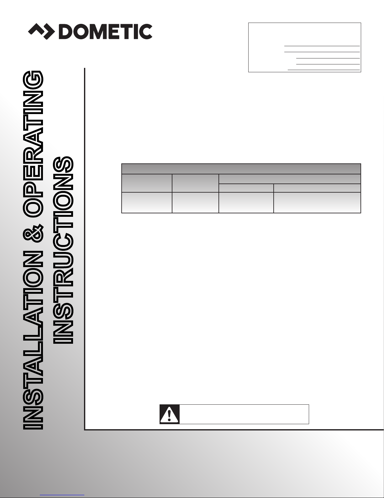
a. Check for obstructions in the area where unit
will be installed. See (FIG. 1).
FIG. 1
Dimensions Are Nominal
Max
Tilt
15°
FIG. 2
2-5/8″
3-7/16″
Roof Opening
3-7/16″
6″
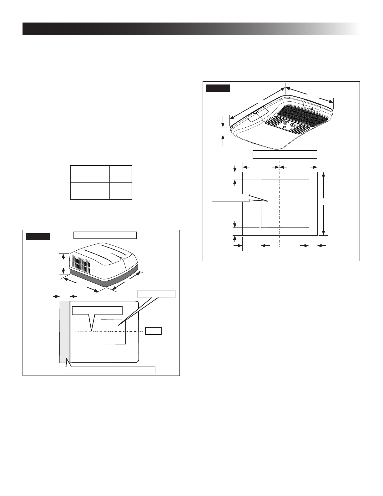
c. Check inside the boat's cabin for air distri-
bution box (hereinafter referred to as "ADB")
obstructions (i.e. space for doors to open,
room dividers, curtains, ceiling xtures, etc.).
See (FIG. 2).
23-1/8″
Dimensions Are Nominal
11-9/16″
11-9/16″
21-1/8″
21-1/8″
2-7/8″
13-1/8″
34-7/8″
18″
Center Line Of Unit
Keep This Area Free Of Obstructions
29-7/8″
Roof Opening
Front
b. Maintain structural integrity.
Otherwise damage to product and/or boat
could occur.
The roof must be designed to support 130
pounds when the boat is in motion. Normally a 200 lb. static load design will meet this
requirement.
B. Roof Preparation
1. FIRE OR ELECTRICAL SHOCK
HAZARD. Verify there are no obstacles inside
boat’s roof and/or walls (wires, pipes, etc.). Shut
OFF gas supply, disconnect 120 Vac power from
boat and disconnect positive (+) 12 Vdc terminal
from supply battery BEFORE drilling or cutting
into boat. Failure to obey these warnings could
result in death or serious injury.
Opening Requirements - Before preparing the ceiling opening, read all of the following instructions before beginning the
installation.
2. Carefully mark and cut the required roof opening.
See "B. Roof Requirements" on page (4).
3. Maintain structural integrity. Otherwise damage to product and/or boat could occur.
NEVER create a low spot on boat
roof. Otherwise, water will pool and could cause
a leak.
5
 Loading...