

Page 1
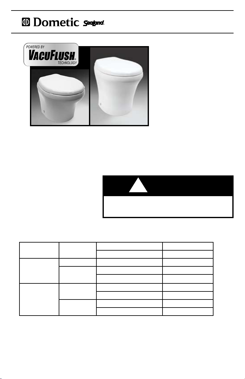
4806 4809, 4848
4800 SERIES VACUFLUSH® TOILETS
INSTRUCTION MANUAL
IMPORTANT NOTICE
VacuFlush® sanitation systems must
be installed according to Dometic’s
recommended procedures.
Do not attempt installation without rst
contacting a VacuFlush® certied dealer or
Dometic Corporation.
This manual must be read and understood before
adjustment, maintenance, or service is performed.
Modification of this product can result in property damage.
WARNING
!
SYSTEM SPECIFICATIONS
Water
Supply
Discharge
Piping
Electrical
System
* See page 8 for further information.
** Each toilet must be on separate circuit breaker. Does not include electrical requirements of vacuum pump.
Water hose
connection
Hose ID Standard 1.5 inch/38 mm
Hose runs
Amp draw
(avg.)
Circuit breaker
Thread size 1/2 inch MPT
Flow rate at toilet 2 GPM/7.6 LPM
Max. horizontal run 50 ft./15 m*
Max. vertical run
12 volts DC 2.0 amps
24 volts DC 1.0 amp
12 volts DC 2 amps**
24 volts DC 2 amps**
6 ft./1.8 m*
Page 2
48 00 S ERIES VA CU FLUSH T OI LE TS
TABLE OF CONTENTS
Product Features 1
System Specications 1
Toilet Specications and Dimensions 2
Toilet Model Identication 3
Warnings 3
Toilet System Components 4
Marine Sanitation Regulations 4
Important Information Before Operation 5
System Start-Up 5
Toilet Operation 5
Service Mode 6
Proper Bowl Cleaning 6
Clearing Discharge Lines 6
Winterizing 7
Maintaining the System 7
Spare Parts 7
Ordering Parts 8
Installation - General Information 8-10
Deodorants and Special Tissue 10
Troubleshooting Guide 11-15
Customer Service and Warranty 16
TOILET SPECIFICATIONS
Model Description Weight
4806
4809
4848
All-ceramic, low-prole vacuum toilet with full-size seat and
bowl. Through-oor discharge.
All-ceramic, standard height vacuum toilet with full-size
seat and bowl. Through-oor discharge.
All-ceramic, standard height vacuum toilet with full-size
seat and bowl. Above-oor discharge.
Weights may vary ± 2-3%. Specications subject to change without notice.
42 lbs.
(19 Kg)
50 lbs.
(22.7 Kg)
50 lbs.
(22.7 Kg)
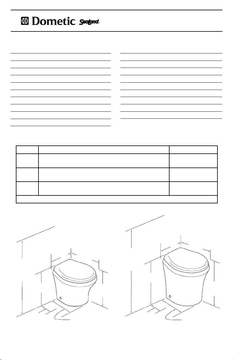
DIMENSIONS
14-3/4 - inch
[375mm]
30-1/4 - inch
[768mm]
Overall height
- seat lid up
14-3/4 - inch
[375mm]
9-3/4 - inch
[248mm]
Back wall to
discharge centerline
rough-in
Model 4806
16-1/4 - inch
[464mm]
13-5/8- inch
[316mm]
Seat Height
14-7/8- inch
[378mm]
Back wall to
front of base
All dimensions may vary ± 3/8-inch (10mm).
33-1/2 - inch
[851mm]
Overall height
- seat lid up
2
discharge centerline
18-1/8 - inch
[460mm]
9-3/4 - inch
[248mm]
Back wall to
rough-in
Models 4809, 4848
14-3/4 - inch
[375mm]
18-5/8 - inch
[473mm]
15-3/4- inch
[400mm]
Back wall to
front of base
17- inch
[452mm]
Seat Height
Page 3
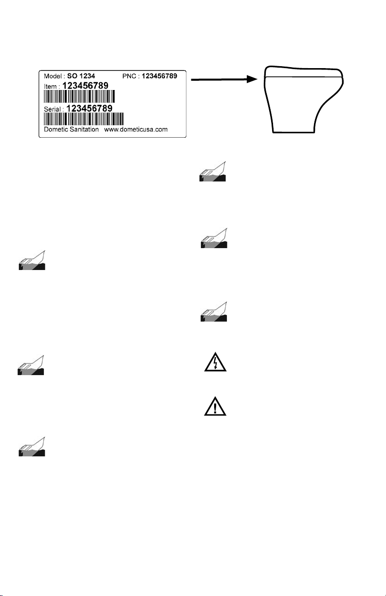
TOILET MODEL IDENTIFICATION
The model identication label is located on the back of the toilet. It shows the model number and serial number of
the product.
WARNINGS
Dometic vacuum toilet systems must be installed
according to Dometic’s recommended procedures.
Dometic also recommends that a qualied marine
technician or electrician install or service this product.
Equipment damage, injury to personnel or death
could result from improper installation. DOMETIC
SANITATION CORPORATION ACCEPTS NO
RESPONSIBILITY OR LIABILITY FOR DAMAGE TO
EQUIPMENT, OR INJURY OR DEATH TO PERSONNEL
THAT MAY RESULT FROM IMPROPER INSTALLATION,
SERVICE OR OPERATION OF THIS PRODUCT.
WARNING!
HAZARD OF FLOODING – If the toilet
system is connected to ANY through-the-hull ttings,
properly installed seacocks MUST be installed in all
piping connected to through-the-hull ttings. Seacocks
MUST be easily accessible to all users of the toilet
system or secondary valves tted in hoses where they
are easily accessible. ALWAYS close seacocks when
toilet system is not in use (even if boat is unattended
for a brief period. All valves MUST be full bore valves
and marine quality. Screw-to-close gate valves are not
recommended. Failure to comply can result in ooding
which can cause loss of property and life.
WARNING!
HAZARD OF FLOODING – If toilet is
connected to ANY through-the-hull ttings, ALL
exible hoses must be of marine sanitation quality
and must be secured to ANY ttings (such as those at
seacock, vented loop or toilet) with two stainless steel,
worm-drive hose band clamps at each connection.
Connections MUST be checked frequently for integrity.
Failure to comply can result in ooding which can
cause loss of property and life.
WARNING!
HAZARD OF FLOODING – If toilet rim is
below the waterline at ANY time (during any conditions
of heel, load or trim) and is connected to ANY throughthe-hull ttings, properly positioned ventilated (vented)
loops MUST be installed in intake* or discharge piping
to prevent potential back siphonage of seawater into
the boat. Failure to do so can result in ooding which
can cause loss of property and life.
* if connected to raw water
HAZARD OF FLOODING – If the toilet
uses fresh water for ushing and is connected
directly or indirectly to a shoreside municipal water
system at ANY time, shoreside water connections
MUST be disconnected if the boat is unattended (even
for a brief period). Failure to comply can result in
ooding which can cause loss of property and life.
HAZARD OF FLOODING – If toilet uses
raw water for ushing at ANY time, a raw water pump
controlled by an automatically operating demand
switch MUST NOT be installed. If the onboard water
valve or any plumbing connections were to leak, the
automatically operated pump would start and could
ood the boat. Failure to comply can cause loss of
property and life.
HAZARD OF FLOODING – Before
beginning any work on this product, be sure that all
electrical power to the unit has been turned off. Failure
to do so can result in ooding which can cause loss of
property and life.
HAZARD OF SHOCK OR FIRE –
Always use recommended fuse, circuit breaker and
wire size. Failure to do so can result in re that can
cause the loss of property and life.
CAUTION:
can create serious damage to the sanitation system,
such as rupturing the holding tank and releasing tank
contents into the bilge. To prevent this possibility,
Dometic strongly recommends the addition of a “full”
tank safety shut-down relay to the toilet’s incoming
electric power wiring. The “full” signal from the holding
tank can be generated by an optional Dometic Tank
Monitor system.
WARNING!
WARNING!
WARNING!
WARNING!
Overlling the holding tank
3
Page 4
48 00 S ERIES VA CU FLUSH T OI LE TS
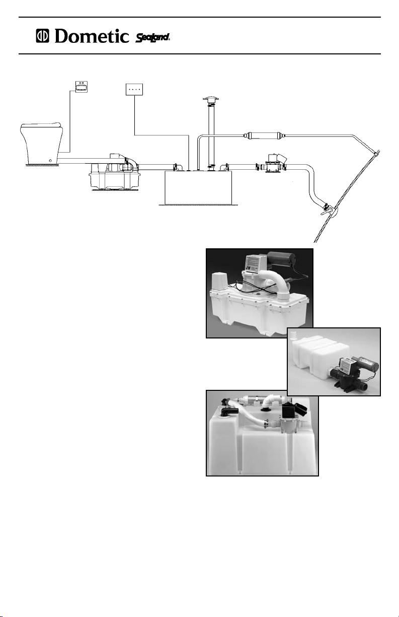
TOILET SYSTEM COMPONENTS
Flush
Switch/
Vacuum
Status
Panel
Vacuum
Toilet
Vacuum
Generator
A VacuFlush 4800 series toilet is part of a total
sanitation system that includes a vacuum source and
usually a holding tank. Because of the wide variation
of boat types and models, Dometic produces a wide
range of vacuum-generating components, holding
tanks and accessories. The VacuFlush system diagram
(above) provides a general orientation to a typical
vacuum sanitation system.
Vacuum Source: A variety of Dometic vacuum sources
provide vacuum energy to move the waste from the
toilet to the holding tank. All consist of a vacuum
storage reservoir and vacuum pump. These can be
separate or combined units (vacuum generators).
Holding Tanks: Many boats are equipped with a
holding tank, and many of those are SeaLand holding
tank systems. SeaLand tanks are available in many
capacities, and can include pre-installed vacuum
generator, tank level monitor, discharge pump,
and other accessories to enhance the comfort and
convenience of marine sanitation.
Tank Monitor
Panel
Holding Tank System
Deck
Discharge
Vent Filter
Discharge
Pump
S-Series
Low-profile
Vacuum
Generator
Vent Fitting
J-Series
Vacuum
Generator
28HTS-T
Holding
Tank
Overboard
Discharge
MARINE SANITATION REGULATIONS
All boats with xed toilets in U.S. waters and in the waters of some other countries are required to have an
operable marine sanitation device (MSD). The VacuFlush vacuum sanitation system, when installed in a boat, is
a holding tank or Type III system as dened by the U.S. Coast Guard. Type III systems permit operation of the
toilet without direct discharge of untreated waste after every ush. Type III systems can be discharged at marina
dockside pump-out stations or, if in coastal waters, a minimum of three miles offshore. Overboard discharge
capability must remain secured while within the three-mile limit. The overboard discharge pump is activated
by a keyed switch in the toilet compartment. This key should be removed at all times except when discharge
pump is operating.
Sewage from any source should not be discharged directly into our waters. If you are interested in learning more
about this issue, please visit our website at www.DometicSanitation.com.
4
Page 5
IMPORTANT INFORMATION BEFORE OPERATION
1. Make sure all guests understand toilet and seacock operation and that the ushing
instruction label is easy for guests to read. The label is located under the seat.
2. Remember, the vacuum pump starts automatically. Shut off electrical power to
the toilet system before servicing and do not leave the boat with the toilet system
electrical power on.
3. Never use solvents, alcohol, chlorine or caustic chemicals, such as laundry bleach
or drain-opening types, in the toilet system.
4. If the toilet system does not operate properly, refer to the Troubleshooting section
and repair as necessary. If problem persists, contact your local VacuFlush dealer or
see the Customer Service section of this manual.
Label located
under toilet seat.
SYSTEM START-UP
1. Fill freshwater tank.
2. Turn on electrical power and water supply to toilet system.
3. Flush water into system by ushing the toilet ve times (press Flush switch and allow each ush cycle to
complete until vacuum pump stops, about 60-90 seconds each).
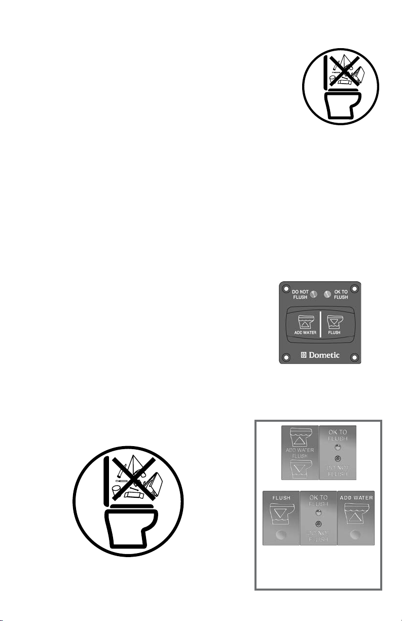
TOILET OPERATION
1. Adding More Water To Toilet Bowl
Press Add Water switch until desired water level is attained. Do not
overll toilet bowl. More water is usually added only when ushing
solids.
2.
Flushing The Toilet
Press the Flush switch down for a moment, then release it. Flush
only when the panel’s green “OK to Flush” light is on. Some models
will not ush unless the “OK to Flush” light is on. It takes about one
minute for vacuum to recharge to the proper level for the next ush.
If the red “Do Not Flush” light is lit, the system is either recharging
the vacuum to the proper level, or the holding tank is full. Do not
ush the toilet during these conditions or system clogs may occur.
3. DO NOT FLUSH FOREIGN OBJECTS
CAUTION!
bodily wastes and rapid-dissolving toilet tissue. Do not ush wet
wipes, sanitary napkins, condoms, diapers, razor blades, paper
cups, cotton swabs, food, hair or liquids such as oils or solvents.
Clogging or damage to the toilet or sanitation system may occur.
VacuFlush toilets are designed to ush only water,
Standard 4800 Flush Switch
Add Water to bowl, press
• To
left side of switch.
• To
Flush, press right side of
switch.
Vimar
Gewiss
Other Dometic Flush/
Add Water Switches with
Status Panels (optional)
5
Page 6

48 00 S ERIES VA CU FLUSH T OI LE TS
SERVICE MODE
To clean toilet bowl or perform other service that requires
keeping the ush ball open without running water, locate the
Service Mode switch at the back left side of the seat mounting
bracket. Slide the switch to the right. (On some models the
Service Switch is a toggle type that’s located on the check valve
of the toilet. It can be reached behind the left side of the toilet
bowl. See page 11 for location.) Press the toilet’s Flush switch
until the ush ball opens, then release it to keep the ush ball
open. Perform the service operation. To close the ush ball and
return to Normal operation, slide the Service Mode switch to the
left.
SERVICE MODE
Switc h behind seat
.
PROPER BOWL CLEANING
For stubborn bowl stains, use SeaLand® Toilet Bowl Cleaner (Fig. A).
It’s manufactured especially for use with all SeaLand toilets. In certain
locations where water is hard, a build-up of lime may dull the toilet bowl
nish. Restore the shine with this SeaLand cleaner. If you cannot nd it
in your area, contact Dometic for your nearest dealer. If the cleaner is not
available, you can also use most non-abrasive bathroom and toilet bowl
cleaners (Bar Keeper's Friend® spray cleaner, Clorox® toilet bowl cleaner,
SaniFlush® toilet bowl cleaner, etc.). Please follow label instructions.
To avoid damaging the Teon®-coated seal,
DO NOT USE
– abrasives (Comet
– caustic chemicals (Drano
– lubricants and cleaners containing alcohols or petroleum distillates
(Pam
® Bar Keepers Friend is a registered trademark of SerVaas Laboratories Inc.
® Clorox, Pine-Sol and Soft Scrub are registered trademarks of The Clorox Co.
® Comet is a registered trademark of Prestige Brands International.
® Drano is a registered trademark of S.C. Johnson & Son Inc.
® Pam is a registered trademark of ConAgra Foods.
® Sani-Flush is a registered trademark of Reckitt Benckiser Inc.
® Teon is a registered trademark of DuPont Co.
® WD-40 is a registered trademark of WD-40 Company.
:
®
cooking spray, Pine-Sol® cleaner, WD-40® lubricant, etc.).
®
, Soft Scrub® cleansers etc.)
®
clog remover, etc.)
Fig. A
EXTENDED PERIODS OF NON-USE –
CLEARING DISCHARGE LINES
Toilet system sanitation hoses should be cleared if toilet will not be needed for an extended period of time (more
than two weeks).
1. Fill toilet bowl with water and add 4 oz. (120 ml) of biodegradable laundry detergent (should
bleach).
2. Open ush ball in Service Mode (see directions above). Hold the Add Water switch down for about two
minutes. Release the Add Water switch and return the Service Mode switch to the Normal position.
3. Turn off water supply to toilet.
4. Flush the toilet without water, allowing the vacuum pump to shut off after the ush. Repeat three times. (This
procedure will minimize any remaining water in the sanitation hoses.)
5. Turn off power to the vacuum pump.
6. Completely pump out holding tank.
If system will be subjected to freezing temperatures, please follow above procedure, then winterize system as
described on next page.
TURN OFF ELECTRICITY AND WATER TO TOILET IF IDLE FOR LONG PERIODS OF TIME
If people will not be using the boat for a long time (vacation, maintenance, off-season, etc.), or in the event of a
long electrical power interruption, electrical power and water supply to the toilet and vacuum generator should be
shut off.
6
NOT contain
Page 7

WINTERIZING
At the end of each season, the VacuFlush toilet system should be winterized for storage. The following procedure
should be used:
1. Pump out holding tank.
2. Thoroughly ush system with fresh water.
3. Drain freshwater tank.
4. Add freshwater antifreeze to freshwater tank.
5. Flush freshwater water antifreeze and water mixture through toilet and into the waste holding tank. Each
installation is different, so amounts may vary. User discretion is required to assure adequate protection.
6. Empty holding tank.
NOTE: Use nontoxic antifreeze designated for potable water systems. (See vehicle owner’s manual.)
Never use automotive-type antifreeze in freshwater systems.
MAINTAINING THE SYSTEM
Maintenance intervals and normal parts replacement vary widely depending on factors such as frequency of
system use, quality of ushing water, etc. The chart below is intended as a general guide in keeping your sanitation
system 100% ready for use at any time.
Maintenance Procedure Service Interval Additional Information
ROUTINE
Check all clamped hose joints below
water line for leaks.
Check lter screen in water valve.
Replace vent lter (if installed in holding
tank vent line).
Monthly
After rst year of service,
then as needed if water ow
is noticeably slower.
Annually
–
Screen is located inside water
valve inlet.
–
MAJOR SYSTEM MAINTENANCE
Replace duckbill valves in vacuum
generator or vacuum pump.
Replace ush ball seal and ush ball
(if required).
Every three years
Every three years
See vacuum generator or
vacuum pump parts list for
replacement kit part number.
See toilet parts list for
replacement kit part number.
SPARE PARTS
Boats operating in remote waters should carry the following parts on board.
Description Where Used
Flush ball seal 4800 series vacuum toilet. See parts list.
Flush ball 4800 series vacuum toilet. See parts list.
Electric water valve 4800 series vacuum toilet. See parts list.
Vacuum switch kit Vacuum tank or vacuum generator. See parts list.
Duckbill valves Vacuum pump or vacuum generator. See parts list.
7
Page 8

48 00 S ERIES VA CU FLUSH T OI LE TS
ORDERING PARTS
Dometic is ready to assist you in the event service is required. Before calling, please have the following information
available. Your cooperation in having this information ready is appreciated and allows us to better meet your needs.
Please refer to Customer Service section in this manual.
1. Toilet Model Number (See Toilet Model Identication section, page 3.)
2. Serial Number
3. Part Number, Description and Quantity (see separate parts list sheet.)
INSTALLATION – GENERAL INFORMATION
Special Installation Notes
1. Each 4800 series toilet installation must include a separate vacuum generator or vacuum pump/tank
combination (available separately).
2. See WARNINGS on page 3 for additional toilet system installation and operation information.
Flush Water Options
FRESH WATER SYSTEM – VacuFlush vacuum toilets
can ush with fresh water or sea water. Fresh water
is highly recommended because it reduces odors
often associated with sea water and reduces system
maintenance.
RAW WATER SYSTEM – VacuFlush vacuum toilets can ush with sea water but require a separate pump and
water ltration for this purpose. Please contact your nearest VacuFlush dealer, distributor, or Dometic Sanitation
sales ofce for complete information.
INSTALLATION NOTES
• See Notes from Freshwater System (above).
• Seacock must be full-ow, marine quality valve
(not screw-to-close type).
• Use primary and secondary raw water lters (see
illustration).
• Position vented loop between discharge side of
water pump and toilet. Must be equipped with
integral check valve that permits air into line to
prevent siphoning.
5/8-in. [16mm] Hose
1-inch [25mm] Hose
Seacock
Small Engine Intake Strainer (Coarse)
To Suction Side of Raw
Water Filter (Fine)
INSTALLATION NOTES
• Use cold water only.
• Water supply line: 1/2-in. (13mm) ID; toilet inlet
tting is 1/2-in. (13mm), 14 TPI.
• Requires 2.0 GPM (7.6 LPM) ow rate at toilet
water valve.
• Include shut-off valve in water line for maintenance
purposes.
Vented loop must be at
least 8 inches [203mm]
above water line in toilet
during all conditions of
heel, trim or load.
Water Line
Raw Water
Pump
Water Pump
100 Mesh
1/2-in. [13mm] Water
Hose
Flush
Switch
Vacuum
Toilet
Discharge Piping (see System Layout, page 4)
HORIZONTAL AND VERTICAL RUNS – All discharge piping and seacocks (including seacocks) must be 1.5-inch
(38 mm) ID nominal pipe size. Maximum vertical piping from toilet outlet to vacuum source inlet is 6 feet (1.8
meters). Maximum horizontal length of vacuum piping from toilet outlet to vacuum source is 50 feet (15 meters).
Other restrictions on discharge piping apply. Contact your nearest VacuFlush dealer, distributor, or Dometic
Sanitation customer service for more information.
8
Page 9

INSTALLATION – GENERAL INFORMATIONINSTALLATION – GENERAL INFORMATION (cont’d)
Discharge Piping Layouts
VacuFlush toilets must be connected to 1.5-inch (38mm) ID exible sanitation hose. Connections can be made
either through the oor or out the rear of the toilet above the oor.
Flexible hoses that contain sewage from any marine toilet will create unpleasant odor that permeates through the
wall of the hose. Avoid this condition by installing the tank in the lowest position in the boat so that hose contents
will drain into the holding tank. Rigid PVC pipe can also be installed in runs that hold trapped sewage. The marine
sanitation hose most resistant to odor permeation is OdorSafe Plus® hose, available from your local SeaLand or
VacuFlush product dealer.
Flush
Switch
Vacuum
Toilet
Vacuum
Toilet
Vacuum
Generator
Flush
Switch
Vacuum
Generator
Wye
Valve
Holding Tank
Problem
Hose
Problem Hose
must use rigid
PVC pipe or
OdorSafe Plus
hose
Holding Tank
Discharge
Pump
Discharge
Pump
Problem
Hoses
Seacock
Seacock
Vented Loops
Ventilated or vented loops are intended to prevent back siphonage of sea water into the toilet. If the toilet rim is
below the waterline at ANY time in ANY conditions of heel, load or trim, a vented loop MUST be installed in the
hose run at a point at least 8-in. (203 mm) above the toilet water line in all such conditions. See vented loop tting
manufacturer’s recommendation for further information.
Vented loop must be at least 8 inches
[203mm] above water line during all
conditions of heel, trim or load.
Heeled Water Line
Water Line
Vacuum
Toilet
Flush
Switch
Vacuum
Generator
Seacock
9
Page 10

48 00 S ERIES VA CU FLUSH T OI LE TS
INSTALLATION – GENERAL INFORMATION (cont’d)
Holding Tanks
VacuFlush toilets operate with most holding tank or
treatment systems. When installed with a holding
tank, the maximum capacity of the tank should be
large enough to avoid the inconvenience of frequent
discharges. A 30-gallon tank (114-liter) will become
full in about 90 ushes.
Electrical Requirements
Refer to wiring diagram on Parts List/Wiring Diagram
sheet (shipped with toilet).
Seacocks
Seacocks are required by various marine
regulations. Only full-ow, marine quality valves
are recommended. Some regulations require the
seacocks be congured so they can be locked in
a closed position. Seacocks MUST be installed
according to the manufacturer’s instructions.
Toilet Installation
See Toilet Mounting Template and instructions on
separate sheet (supplied with toilet).
DEODORANTS AND SPECIAL TISSUE
Your VacuFlush toilet system may require the regular addition of a deodorant product to reduce malodors and to
help break down holding tank contents. Several factors should be considered in selecting a deodorant product.
Liquid or Granulated. Liquid products work more quickly by readily going into solution. Granulated powder
formulations have the advantage of requiring less storage space and are less likely to leak if the package is
inadvertently damaged.
Formaldehyde versus Non-Formaldehyde. Dometic manufactures both types of deodorants. Generally
speaking, formaldehyde formulas control odor very effectively at all temperatures and with all degrees of water
hardness. Both SeaLand® Environment-Friendly and Clean ‘n Green™ brands, which are formaldehyde-free, are
similarly effective.
How Much Deodorant and How to Add It. The deodorant is added directly into the toilet bowl, then ushed
into the holding tank. Follow bottle or package instructions. Conditions of extremely warm weather, longer waste
holding time and larger tank capacities may require more deodorant treatment. Also, to maintain optimum
efciency in odor control, the waste holding tank should be cleaned thoroughly at least once or more each season
depending on use.
Why Not Use Household Toilet Paper in Your Toilet. Household tissues often contain adhesives which bond
together the paper bers from which the tissue is made. The adhesives prevent the tissue from breaking apart, and
their use in “ultra-low ow” systems can cause system clogging. SeaLand tissue is especially designed for use in
low water toilet systems. Its rapid-dissolving properties minimize the amount of residual paper in the holding tank
and allow deodorizers to work more efciently.
SeaLand Brand versus Other Brands. We constantly strive to provide our system owners with effective products
that have minimal environmental impact and good value. Many deodorant products do not measure up to our
standards of performance and value.
SeaLand®
Rapid-Dissolving
Toilet Tissue
Four 400-sheet rolls
Part No. 379441204
SeaLand®
Cleaner
16-oz. bottle
Part No.
379314016
SeaLand®
Clean ‘n Green
Bowl Cleaner/Tank Deodorant
12-2 oz. drop-in pouches
Part No. 379512602
10
SeaLand® Liquid
Deodorant -
Environment Friendly
32-oz. bottle
Part No.
379114032
Page 11

TROUBLESHOOTING GUIDE
Toilet base assembly
Check Valve
SERVICE MODE
Toggle Switch
(alternate location
on some models)
Electric Water
Valve
Filter
Screen
Drive Arm
Linkage
Flush
Spring
Circuit Board
Sealing
Grommet
Motor
Bowl Seal
Flush Ball Seal
Retaining Ring
Flush Ball
Rotor Shaft Cam
Cam Switch
Problem Possible Cause Service Instructions
1. Water does not enter bowl
and toilet does not ush.
2. Water enters toilet bowl, but
toilet does not ush.
a. Toilet fuse is blown or circuit
breaker is tripped.
b. Loose wiring connections.
c. Incorrect wiring of toilet to
incoming power.
d. Defective circuit board.
a. Electrical failure from ush switch
to toilet.
b. Flush switch may be defective.
c. Loose ush ball motor wires.
d. Defective ush ball motor.
e. Flush ball motor drive arm failure.
f. Drive linkage failure.
g. 4800L & 4800WL series require
“OK to Flush” light to be lit for
toilet to ush.
11
a. Check toilet fuse or circuit
breaker.
b. Check for loose or defective
wiring at circuit board pins 9
and 10.
c. Check for reverse polarity of
incoming power.
d. Replace circuit board.
a. Check for loose or defective
wiring between ush switch
and circuit board pins 2 and 4.
b. Replace if necessary.
c. Check for loose wires between
motor and circuit board pins 17
and 18.
d. Replace if necessary.
e. See page 15 for replacement
instructions.
f. See page 15 for replacement
instructions.
g. Check for loose or defective
wires between vacuum switch
on vacuum generator and pin 6
of circuit board.
Page 12

48 00 S ERIES VA CU FLUSH T OI LE TS
TROUBLESHOOTING GUIDE (cont’d)
Problem Possible Cause Service Instructions
3. Water does not enter toilet
bowl, but toilet ushes.
4. Water does not enter toilet in
“Add Water” switch position.
5. Water does not shut off and
toilet bowl overows.
6. Flush ball cycles constantly
between open and closed
positions.
7. Flush ball opens slowly.
8. Flush switch must be held in
FLUSH position to close ush
ball.
9. Flush ball does not close
completely.
10. Flush ball does not open
completely.
11. Squeaky noise occurs during
ush cycle.
a. Blocked water supply.
b. Loose or defective wiring.
c. Defective water valve.
d. Defective circuit board.
a. Electrical failure.
b. Defective ush switch.
a. Debris inside water valve or
defective water valve.
a. Electrical short circuit.
b. Cam switch needs adjustment to
align ush ball.
c. Defective cam switch.
d. Defective drive linkage.
a. Excessive drag between ush ball
and seal.
b. Defective spring assembly.
a. Loose or defective wiring.
b. Defective cam switch.
c. Service Mode switch is in Service
position.
a. Cam switch needs adjustment/
ush ball alignment or replacement.
b. Rotor cam shaft loose or
defective.
a. Rotor cam shaft is loose or
defective.
b. Weak or defective spring
assembly.
c. Excessive drag between ush
ball and seal.
a. Lubrication needed between ush
ball and seal.
b. Lubrication needed between drive
arm/linkage joint.
a. Clear blockage in water line or
lter screen at water valve inlet.
b. Check wiring between water
valve and circuit board pins 15
and 16.
c. Replace if necessary.
d. Replace circuit board.
a. Check for loose or defective
wiring between ush switch
and circuit board pins 1 and 4.
b. Replace if necessary.
a. Replace water valve.
a. Check wiring between ush
switch and circuit board pins 1
and 4.
b. See page 14 for cam
switch adjustment/ush ball
alignment.
c. Replace cam switch. See page
15 for replacement details.
d. Replace drive linkage. See
page 15 for details.
a. Clean surface of ush ball and
under edge of seal. Lubricate
with alcohol-free cooking spray.
b. Replace spring.
a. Check wiring between cam
switch and circuit board pins
11 and 12.
b. Replace cam switch. See page
15 for details.
c. Return Service Mode switch to
Normal position.
a. See adjustment/alignment or
replacement details on page
14.
b. See replacement instructions
on page 15.
a. See instructions for repair or
replacement on page 15.
b. Replace spring.
c. Clean surface of ush ball and
under edge of seal. Lubricate
with alcohol-free cooking
spray.
a. Lubricate with alcohol-free
cooking spray.
b. Lubricate joint with silicone
grease.
12
Page 13

TROUBLESHOOTING GUIDE (cont’d)
Problem Possible Cause Service Instructions
12. Water does not stay in toilet
bowl (leaks between ush ball
and seal).
13. Toilet ushes in both ADD
WATER and FLUSH position.
14. Water leaks from toilet onto
oor.
15. Green OKAY TO FLUSH light
does not illuminate.
16. Red DO NOT FLUSH light
does not illuminate.
17. Flush ball opens and closes,
but waste does not leave
bowl (no vacuum).
a. Flush ball seal is worn and needs
replaced.
b. Flush ball is scratched or worn
and needs replaced.
c. Cam switch/ush ball alignment
needs adjustment.
d. Bolts that hold base to toilet need
tightened to 20-25 in.-lbs.
a. Defective circuit board.
a. Loose water line connection.
b. Defective water valve.
c. Toilet bowl seal is defective.
d. Mounting bolts holding base to
toilet need tightened to 20-25
in.-lbs.
a. Loose wire at circuit board.
b. Loose wire at Flush Switch.
c. Loose or defective wire between
vacuum switch and toilet.
d. Defective green light.
a. Loose wire at circuit board.
b. Loose wire at Flush Switch.
c. Loose or defective wire between
vacuum switch and toilet.
d. Loose or defective wire between
tank FULL relay and toilet circuit
board pin 8.
e. Defective red light.
a. No electrical power to vacuum
pump.
b. Tank FULL shut-down relay
prevents vacuum pump from
operating.
c. Blockage inside bottom of toilet
base.
a. See instructions on page 15 for
replacement.
b. See instructions on page 15 for
replacement.
c. See instructions on page 14 for
adjustment.
d. DO NOT OVERTIGHTEN or
damage to toilet may occur.
a. Replace circuit board.
a. Tighten water line connections.
b. Replace water valve.
c. Replace bowl seal. See
instructions on page 15.
d. DO NOT OVERTIGHTEN or
damage to toilet may occur.
a. Check wires at pins 3 and 6 of
circuit board.
b. Check green wire at Flush
Switch.
c. Repair or replace wires.
d. Replace Status Panel.
a. Check wires at pins 5, 7 and 8
of circuit board.
b. Check red wire at Flush Switch.
c. Repair or replace wires.
d. Repair or replace wire.
e. Replace status panel.
a. Check power wires, fuse or
circuit breaker to vacuum
pump.
b. Pump out holding tank.
c. See instructions below to clear
blockage.
Clearing Blockage in Toilet Base
1. Turn off water to the toilet.
2. Open the ush ball in Service Mode.
3. Pull the foreign material from the 1-inch diameter orice at the bottom of the base or, using a small diameter
blunt rod, attempt to push the blockage through the orice.
Locating Potential Vacuum Leaks in Toilet Base
The VacuFlush toilet is part of a vacuum system that includes a vacuum pump and vacuum tank, or a vacuum
generator and discharge plumbing lines. If a vacuum leak is suspected, special equipment will isolate the source of
the leak. If the toilet is determined to be the source of the leak, there are three possible areas to investigate:
1. Flush ball and ush ball seal. See Problem 12 in Troubleshooting Guide.
2. O-rings on the rotor shaft.
3. O-rings around bottom of toilet base assembly.
Sources 1 and 2 will require the base assembly to be removed from the toilet and partially disassembled.
13
Page 14

48 00 S ERIES VA CU FLUSH T OI LE TS
TROUBLESHOOTING GUIDE (cont’d)
Adjusting cam switch/flush ball
alignment
The ush ball should be properly positioned so that
the “A” and “B” distances are equal (see illustration at
right). If the ush ball becomes misaligned (resulting in
water leaking from bowl or other ushing problems),
follow instructions below to resolve problem.
REMOVING TOILET FROM FLOOR
1. Turn off water and electrical power to
toilet.
2. Remove water inlet hose from toilet.
3. Remove toilet from oor and turn it upside down.
MAKE SURE POWER WIRES REMAIN SECURE.
TO CORRECT PROBLEMS 6b, 9a and 12c:
4. Loosen cam switch mounting screws with 3/32inch hex tool and 1/4-inch box-end wrench. Slide
cam switch up or down (see illustrations below)
depending on ush ball position.
5. Tighten cam switch mounting screws, apply
electrical power and check adjustment. Repeat as
necessary.
6. After cam switch and ush ball are properly
positioned, connect water line and reinstall toilet.
OVER-TRAVEL CONDITION
back
Slide cam switch down.
UNDER-TRAVEL CONDITION
front back front
Slide cam switch up.
14
Page 15

TROUBLESHOOTING GUIDE (cont’d)
Replacing the flush ball seal and bowl seal
1. Turn off water and electrical power to toilet.
2. Remove water inlet hose from toilet.
3. Remove toilet from oor and turn it upside down.
Disconnect Service Switch wires at
in-line connectors.
4. Remove three nuts and at washers securing base
assembly to toilet bowl using a 1/4-inch drive ratchet
wrench, 7/16-inch deep-well socket and extension.
5. Pull check valve out of the sealing grommet located
in rear of toilet bowl.
6. Lift base assembly from toilet.
7. Replace old seals with a complete seal kit.
8. Reconnect base assembly to toilet with new
mounting bolts (L-shaped) included with seal kit.
Tighten nuts to 20-25 in.-lbs. torque.
9. Reconnect Service Switch wires. Reattach water
inlet hose to toilet.
10. Reinstall toilet to oor.
Replacing the flush ball
1. Turn off water to toilet.
2. Open ush ball in Service Mode, then turn off power
to toilet.
3. Disconnect water inlet hose.
4. Remove toilet from oor and turn upside down,
and disconnect Service Switch wires at in-line
connectors.
5. Pull check valve out of sealing grommet located in
rear of toilet bowl.
6. Remove three nuts and at washers securing base
assembly to ceramic toilet bowl using a 1/4-inch
drive ratchet wrench, 7/16-inch deep-well socket
and extension.
7. Lift base assembly from toilet.
8. Remove bowl seal, ush ball seal, and retainer plate
to expose ush ball.
9. Loosen set screw in the rotor shaft cam using
a 1/8-inch hex tool.
10. Remove the #8 x 1/4-inch long screw and at washer
from linkage slot.
11. Remove the four screws securing the mounting
bracket to base.
12. Pull mounting bracket and rotor cam off base.
13. Rotate ush ball forward and remove ush ball
retaining screw.
14. Replace ush ball and reverse disassembly through
step 10.
15. Push rotor cam all the way onto rotor shaft. Tighten
set screw.
16. Lubricate moving parts with silicone grease.
17. Before reassembling entire toilet, the cam switch
may require adjustment. See “Adjusting The Cam
Switch” on page 14.
Replacing the rotor shaft
1. Follow disassembly steps 1 through 14 under
“Replacing the Flush Ball”.
2. Pull rotor shaft out from inside of the base.
3. Lubricate O-rings on new shaft with silicone grease.
4. Align at section on rotor shaft with at section in
cam during assembly. Push rotor shaft cam fully
onto rotor shaft. Tighten set screw.
5. Lubricate moving parts with silicone grease.
6. Reverse the disassembly procedure.
7. Before attaching base to toilet, the cam
switch may require adjustment. See
“Adjusting The Cam Switch” on page 14.
Replacing the rotor shaft cam
1. Follow disassembly steps 1 through 14 under
“Replacing the Flush Ball”.
2. Remove linkage pin clip and pin.
3. Attach new rotor shaft cam to linkage using
pin and clip.
4. Lubricate moving parts with silicone grease.
5. Reverse the disassembly procedure.
6. Before attaching base to toilet, the cam
switch may require adjustment. See
“Adjusting The Cam Switch” on page 14.
Replacing the motor drive arm
1. Follow disassembly steps 1 through 11 under
“Replacing the Flush Ball”.
2. Remove the four motor mounting screws.
3. Remove the motor from the mounting bracket.
4. Loosen the Drive Arm set screw using a 3/32-inch
hex tool, then remove old Drive Arm.
5. Install new Drive Arm and push onto motor shaft as
far as possible. Tighten the set screw.
6. Lubricate moving parts with silicone grease.
7. Reverse disassembly procedure.
8. Before attaching base to toilet, the cam
switch may require adjustment. See
“Adjusting The Cam Switch” on page 14.
Replacing the drive linkage
1. Follow disassembly steps 1 through 13 under
“Replacing The Flush Ball”.
2. Remove linkage pin clip and pin at rotor shaft cam.
3. Remove the ush spring retaining screw and washer
from the retaining post.
4. Remove the ush spring from the old linkage.
5. Insert the ush spring into the new linkage
and reattach the spring to the retaining post.
6. Attach linkage to rotor shaft cam using pin
and clip.
7. Lubricate moving parts with silicone grease.
8. Reverse the disassembly procedure.
15
Page 16

48 00 S ERIES VA CU FLUSH T OI LE TS
CUSTOMER SERVICE
There is a strong, worldwide network to assist in
servicing and maintaining your sanitation system.
For the Authorized Service Center near you, please
call from 8:00 a.m. to 5:00 p.m. (ET) Monday through
Friday.
Telephone: 1 800-321-9886 U.S.A. and Canada
330-496-3211 International
Fax: 330-496-3097 U.S.A. and Canada
330-496-3220 International
Website: http://www.DometicSanitation.com
http://www.DometicSanitation.com/locate.asp
MANUFACTURER’S ONE-YEAR LIMITED WARRANTY
Dometic Corporation warrants, to the original purchaser only, that this VacuFlush vacuum discharge toilet, if used
for personal, family or household-like purposes, and if installed according to Dometic’s recommended procedures,
is free from defects in material and workmanship for a period of one (1) year from the date of purchase.
If this Dometic product is placed in commercial or business use, it will be warranted, to the original purchaser only,
to be free of defects in material and workmanship for a period of ninety (90) days from the date of purchase.
Dometic reserves the right to replace or repair any part of this product that proves, upon inspection by Dometic,
to be defective in material or workmanship. All labor and transportation costs or charges incidental to warranty
service are to be borne by the purchaser-user.
EXCLUSIONS
IN NO EVENT SHALL DOMETIC BE LIABLE FOR INCIDENTAL OR CONSEQUENTIAL DAMAGES, FOR
DAMAGES RESULTING FROM IMPROPER INSTALLATION, OR FOR DAMAGES CAUSED BY NEGLECT, ABUSE,
ALTERATION, OR USE OF UNAUTHORIZED COMPONENTS. THIS INCLUDES FAILURES WHICH MAY RESULT
FROM NOT FOLLOWING THE WINTERIZATION OR CLEANING PROCEDURES AS DESCRIBED IN THIS MANUAL.
ALL IMPLIED WARRANTIES, INCLUDING ANY IMPLIED WARRANTY OF MERCHANTABILITY OR FITNESS FOR
ANY PARTICULAR PURPOSE, ARE LIMITED TO A PERIOD OF ONE (1) YEAR FROM DATE OF PURCHASE.
IMPLIED WARRANTIES
No person is authorized to change, add to, or create any warranty or obligation other than that set forth herein.
Implied warranties, including those of merchantability and tness for a particular purpose, are limited to one (1)
year from the date of purchase for products used for personal, family or household-like purposes, and ninety (90)
days from the date of purchase for products placed in commercial or business use.
OTHER RIGHTS
Some states do not allow limitations on the duration of an implied warranty, and some states do not allow
exclusions or limitations regarding incidental or consequential damages; so, the above limitations may not apply to
you. This warranty gives you specic legal rights, and you may have other rights which vary from state to state. To
obtain warranty service, rst contact your local dealer from whom you purchased this product.
You may also contact or have your local dealer contact
the Parts Distributor nearest you for quick response to
your replacement parts needs. They carry a complete
inventory for the SeaLand product line.
Dometic is a customer-driven, world-leading provider
of innovative leisure products for the caravan,
motor-home and marine markets. Dometic offers
a complete range of air conditioners, refrigerators,
awnings, cookers, sanitation systems, lighting,
windows, doors and other equipment that makes
leisure life more comfortable away from home.
Dometic also provides refrigerators for specic use
in hotel rooms, ofces and for storage of medical
products and wine. Dometic’s products are sold
in almost 100 countries and are produced mainly
in Dometic’s own production facilities around the
world. Dometic has more than 4,400 employees.
16
® Registered; ™ Trademark of Dometic Corporation
© Dometic Corporation
600345371 2/08
13128 SR 226 | BIG PRAI RIE, OHIO 446 11 USA
www.Do metic Sanita tion.co m
 Loading...