

Page 1

®
Dolphin
For
Windows Mobile
Windows Mobile
Windows
®
CE 5.0 (Dolphin 6100, 6500, 7600)
Power Tools
®
5.0
®
2003 Second Edition
User’s Guide
Page 2

Disclaimer
Honeywell International Inc. (“HII”) reserves the right to make changes in specifications and other
information contained in this document without prior notice, and the reader should in all cases consult HII
to determine whether any such changes have been made. The information in this publication does not
represent a commitment on the part of HII.
HII shall not be liable for technical or editorial errors or omissions contained herein; nor for incidental or
consequential damages resulting from the furnishing, performance, or use of this material.
This document contains proprietary information that is protected by copyright. All rights are reserved. No
part of this document may be photocopied, reproduced, or translated into another language without the
prior written consent of HII.
©2007–2010 Honeywell International Inc. All rights reserved.
Web Address: www.honeywellaidc.com
Trademarks
Dolphin, Dolphin RF, HomeBase, Mobile Base, and QuadCharger are trademarks or registered
trademarks of Hand Held Products, Inc. or Honeywell International Inc.
Microsoft, Windows, Windows Mobile, Windows CE, Windows NT, Windows 2000, Windows ME,
Windows XP, ActiveSync, Outlook, and the Windows logo are trademarks or registered trademarks of
Microsoft Corporation.
Other product names mentioned in this manual may be trademarks or registered trademarks of their
respective companies and are the property of their respective owners.
Patents
Please refer to the product packaging for a list of patents.
Other Trademarks
The Bluetooth trademarks are owned by Bluetooth SIG, Inc. U.S.A. and licensed to Honeywell.
Page 3

Table of Contents
Chapter 1 - Accessing and Upgrading Power Tools
Dolphin Power Tools Overview............................................................................................1-1
Software Requirements .......................................................................................................1-2
Dolphin Power Tools Main Window .....................................................................................1-2
Additional Dolphin Power Tools ...........................................................................................1-4
Dolphin 6100, 6500, and 7600 Power Tools........................................................................1-5
Upgrading Power Tools .......................................................................................................1-6
Chapter 2 - EZConfig
EZConfig Editor....................................................................................................................2-2
Sample EXM Files..........................................................................................................2-2
Opening EZConfig Editor on the Workstation ................................................................2-3
Menu and Toolbar Options ..................................................................................................2-3
File Menu .......................................................................................................................2-3
Working with Open EXM Files .......................................................................................2-7
Working with Sections....................................................................................................2-7
Working with Keys........................................................................................................2-11
Creating New Configuration Documents......................................................................2-14
Associating Applications ..............................................................................................2-15
Registry Documents...........................................................................................................2-16
Processing Registry Documents on the Terminal ........................................................2-18
Creating Bar Codes ...........................................................................................................2-19
Converting Known INI and MNU Files ...............................................................................2-25
EZConfig Editor on the Terminal........................................................................................2-27
Editing Sections ...........................................................................................................2-28
Editing Keys .................................................................................................................2-29
Launching Associated Applications..............................................................................2-30
EZConfig Client..................................................................................................................2-31
Using EZConfig Client..................................................................................................2-31
EZConfig Client Window ..............................................................................................2-33
Command Line Arguments ..........................................................................................2-34
Chapter 3 - DeviceConfig
DeviceConfig.exm File .........................................................................................................3-1
Settings in Control Panel Applets...................................................................................3-1
DeviceConfig.exm Sections and Keys .................................................................................3-2
Connections Section ......................................................................................................3-2
Radio Manager Section..................................................................................................3-2
System Section ............................................................................................................3-12
Applications Section.....................................................................................................3-15
Launching DeviceConfig.exe Manually..............................................................................3-17
Temporary Option for Bar Code Deployment ....................................................................3-17
iii
Page 4

Chapter 4 - Startup Power Tools
Autorun ................................................................................................................................ 4-1
Autorun.exm File............................................................................................................ 4-1
Start Options.................................................................................................................. 4-5
AutoInstall............................................................................................................................ 4-7
Program Install Locations .............................................................................................. 4-7
AutoInstall.exm .............................................................................................................. 4-8
Command Line Arguments............................................................................................ 4-8
Chapter 5 - ScanWedge
Enabling ScanWedge .......................................................................................................... 5-1
ScanWedge.exm Sections .................................................................................................. 5-2
Settings Section............................................................................................................. 5-3
Comm Section ............................................................................................................... 5-6
Decode Section .............................................................................................................5-9
Centering Section ........................................................................................................ 5-12
Formatting.................................................................................................................... 5-13
Symbologies Section ................................................................................................... 5-18
VK (Virtual Key) Mapping Section ...............................................................................5-21
Virtual Key Codes Table.................................................................................................... 5-22
Command Line Arguments................................................................................................ 5-27
Chapter 6 - Additional Power Tools
BattMon ............................................................................................................................... 6-2
InstallerCE ........................................................................................................................... 6-4
HotKeys ............................................................................................................................... 6-5
Keyboard Status .................................................................................................................. 6-7
NoSIP .................................................................................................................................. 6-9
RASMan ............................................................................................................................ 6-11
Reboot ............................................................................................................................... 6-14
Suspend ............................................................................................................................ 6-15
SysInfo............................................................................................................................... 6-16
Chapter 7 - Battery Analyzer
Requirements ...................................................................................................................... 7-1
Recommendation........................................................................................................... 7-1
Analyzing a Battery.............................................................................................................. 7-2
Stopping an Analyze Cycle............................................................................................ 7-2
Command Line Arguments.................................................................................................. 7-3
Advanced Mode...................................................................................................................7-3
Chapter 8 - RegEdit
Editing the Registry ............................................................................................................. 8-1
Menus.................................................................................................................................. 8-3
File Menu.......................................................................................................................8-3
Edit Menu.......................................................................................................................8-3
View Menu..................................................................................................................... 8-4
iv
Page 5

Importing Registry Files....................................................................................................... 8-5
Exporting Specific Registry Settings.................................................................................... 8-6
Other Export Options..................................................................................................... 8-6
Backing Up the Registry ...................................................................................................... 8-6
Restoring the Registry ................................................................................................... 8-7
RegBackup .......................................................................................................................... 8-8
Command Line Arguments................................................................................................ 8-10
Dolphin 7600 Registry Power Tools .................................................................................. 8-11
Registry Edit Options in EZConfig ..................................................................................... 8-13
Chapter 9 - EZMenu
Default EZMenu Configuration Files.................................................................................... 9-1
Menu Configuration File Sections........................................................................................ 9-3
Start Options.................................................................................................................. 9-6
Locking Down the Application Window................................................................................ 9-9
Chapter 10 - Network Utilities
Accessing Network Utilities .............................................................................................. 10-1
IP Config............................................................................................................................ 10-2
Ping ...................................................................................................................................10-4
Route ................................................................................................................................. 10-6
WiFi Status ...................................................................................................................... 10-10
Backup Radio Settings .................................................................................................... 10-12
Restore Radio Settings.............................................................................................. 10-12
Chapter 11 - SetRAM
Accessing SetRAM............................................................................................................ 11-2
RAM Memory Allocation in DeviceConfig.......................................................................... 11-2
SetRAM Window ............................................................................................................... 11-2
RAM Memory Restrictions................................................................................................. 11-3
Chapter 12 - Print Power Tools
Print Demo......................................................................................................................... 12-1
BTPrint............................................................................................................................... 12-1
Chapter 13 - Customer Support
Technical Assistance......................................................................................................... 13-1
Online Technical Assistance........................................................................................ 13-1
v
Page 6

vi
Page 7

1
Accessing and Upgrading Power Tools
Dolphin Power Tools Overview
Dolphin Power Tools are installed in every Dolphin terminal. Different versions of Power Tools apply to
different Dolphin terminals depending on their model or operating system. Consequently, screen captures
that appear in this document may contain tools that do not apply to your device. Please consult the
following table.
Power Tool
AutoInstall
Autorun
Battery Analyzer
BattMon
DeviceConfig
EZConfig Editor
EZConfig Client
EZMenu
HotKeys
Keyboard Status
Network Utilities:
Windows Mobile
5/6
6.0: 7600 (GSM)
5.0: 7850/7900/
9500/
••••
••••
•
•••
••••
••••
••••
••••
••
•••
Windows Mobile
2003 Second
Edition
7900/9500 7600 6100/6500
Windows CE
5.0
Windows CE
5.0
IPConfig
Ping
Route
WiFi Status
Backup Radio Settings
Restore Radio Settings
NoSIP
RASMan
Reboot
RegBackup
RegEdit
RegRestore
••••
••••
••••
•
•
•
••
••
••••
••••
••••
••••
1 - 1
Page 8
Power Tool
Windows Mobile
5/6
Windows Mobile
2003 Second
Edition
Windows CE
5.0
Windows CE
5.0
ScanWedge
SetRAM
Suspend
SysInfo
••••
•
••••
••••
Software Requirements
Dolphin Terminals
Power Tools are designed to work with the following mobile device platforms:
•Microsoft
•Microsoft
•Microsoft
•Microsoft
Desktop
The Power Tools installer and the workstation version of EZConfig Editor are designed to work with the
following operating systems:
•Microsoft
•Microsoft
•Microsoft
•Microsoft
•Microsoft
®
Windows Mobile® 2003 Software for Pocket PCs
®
Windows Mobile® 2003 Second Edition Software for Pocket PCs
®
Windows Mobile® 5.0
®
Windows® CE 5.0 (Dolphin 7600, 6100, 6500)
®
Windows® XP
®
Windows® 2000
®
Windows® NT
®
.NET Framework 2.0
®
ActiveSync® (version 4.2 or higher)
Dolphin Power Tools Main Window
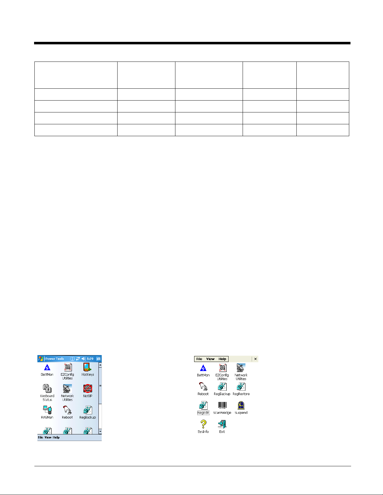
Note: Check the Dolphin Power Tools Overview (see page 1-1) to determine the applicable tools for your device.
On Windows Mobile-based Dolphins,
Start > Power Tools.
tap
1 - 2
On the Dolphin 7600, 6100, 6500
tap Start > Programs > Power To ols.
Page 9
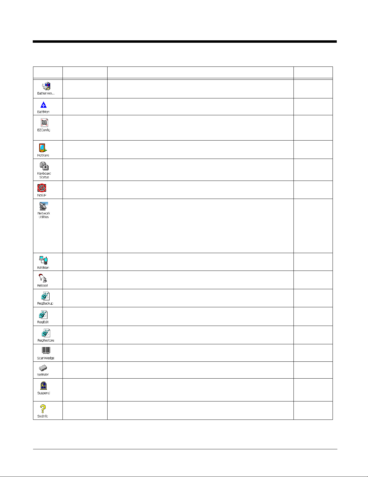
Icon Name Description See Page
Battery
Analyzer
BattMon Programs the LEDs on the top panel to monitor battery power. 6-2
EZConfig
Utilities
HotKeys* Activates button assignments in the Buttons setting. 6-5
Keyboard
Status*
NoSIP* Turns off the Soft Input Panel (SIP) in every application window. 6-9
Network
Utilities
RASMan* Establishes a remote access service (RAS) connection. 6-11
Helps manage the battery. 7-1
Opens a window that displays the EZConfig utilities on the terminal.
• EZConfig Editor on the Terminal (see page 2-27)
• EZConfig Client (see page 2-31)
Puts an icon on the Navigation bar that indicates the alpha-numeric
status of the keyboard.
Opens a window that displays the Network utilities:
• IP Config (see page 10-2)
• Ping (see page 10-4)
• Route (see page 10-6)
• WiFi Status (see page 10-10)
• Backup Radio Settings (see page 10-12)
• Restore Radio Settings (see page 10-12)
2-1
6-7
10-1
Reboot Performs a warm or cold boot from the touch screen, as opposed to
the keyboard commands.
RegBackup Backs up the registry. 8-6 & 8-11
RegEdit Allows you to edit the registry and import and export registry keys. 8-1
RegRestore Loads the RegBackup file. 8-7 & 8-12
ScanWedge Enables the Dolphin terminal to interpret as keystrokes data
received via the decoder, serial port, or IrDA interface.
SetRAM* Allows you to re-set the memory allocation; applies only to Windows
Mobile 5.0-based terminals.
Suspend Manually puts the terminal into Suspend mode from the touch
screen, as opposed to the keyboard commands or time-out
settings.
SysInfo Displays system information. 6-16
6-14
5-1
11-1
6-15
1 - 3
Page 10

Exiting the Power Tools Main Window
• Scroll down and tap the Exit icon .
•Tap File > Exit (ESC).
• Press ESC on the keyboard.
View Options
The View menu changes the organization of the Power Tools main window and is located at the bottom
(Windows Mobile) or the top (Windows CE) of the screen. A checkmark appears next to the selected view.
This menu enables you to choose between:
•Small Icon View
• Large Icon View (Default view)
•List View
• Detail View (This view displays a description of the Power Tool in a column to the right of the name.)
Additional Dolphin Power Tools
These Power Tools are in the Dolphin terminal but do not appear on the main window.
Note: The storage location on the Dolphin 6100/6500 is \Honeywell.
Name Function Storage Location Access Location Page
AutoInstall Installs CAB files after a
hard reset.
AutoRun Programs which
applications launch at
startup.
BTPrint Prints to a Bluetooth
device.
DeviceConfig Configures the terminal
EZMenu Programs custom
application windows.
\IPSM (\Honeywell
for 6100/6500)
\IPSM (\Honeywell
for 6100/6500)
\Program
Files\Power Tools
\IPSM (\Honeywell
for 6100/6500)
\Program
Files\Power Tools
\IPSM\AutoInstall
(\Honeywell for
6100/6500)
\IPSM (\Honeywell
for 6100/6500)
\Program
Files\Power Tools
\IPSM
Dolphin 7600:
\Program
Files\Power Tools
\IPSM\*Menu.exm files
(\Honeywell for
6100/6500)
4-7
4-1
12-1
3-1
9-1
1 - 4
Page 11

Name Function Storage Location Access Location Page
InstallerCE Stores CAB files after they
install instead of deleting
them.
\Program
Files\Power Tools
You do not launch
InstallerCE.
4-1
Dolphin 6100, 6500, and 7600 Power Tools
The Dolphin 6100, 6500, and 7600 with Windows CE 5.0 contain the following Power Tools (except where
noted):
• AutoInstall (see page 4-7)
• Autorun (see page 4-1)
• BattMon (see page 6-2) (does not apply to Dolphin 6100/6500)
• BTPrint (see page 12-1)
• DeviceConfig (see page 3-1)
• EZConfig (see page 2-1)
• EZMenu (see page 9-1)
• IP Config (see page 10-2)
• InstallerCE (see page 6-4) (does not apply to Dolphin 6100/6500)
• Ping (see page 10-4)
• Reboot (see page 6-14)
• RegBackup (see page 8-8)
• RegEdit (see page 8-1)
• RegRestore (see page 8-12)
• Route (see page 10-6)
• ScanWedge (see page 5-1)
• Suspend (see page 6-15)
• SysInfo (see page 6-16)
1 - 5
Page 12
Upgrading Power Tools
Dolphin Power Tools come loaded in every Dolphin terminal and are included in system upgrades. The
Power Tools CAB file is part of a Demos and Power Tools upgrade.
Acquiring Upgrades
Upgrades are available from Customer Support (see page 13-1) or www.honeywellaidc.com.
Installing an Upgrade to the Workstation
Dolphin Power Tools upgrades come in the form of an upgrade executable that installs upgrade files to
the workstation and transfers the appropriate upgrade files to the Dolphin terminal.
Requirements
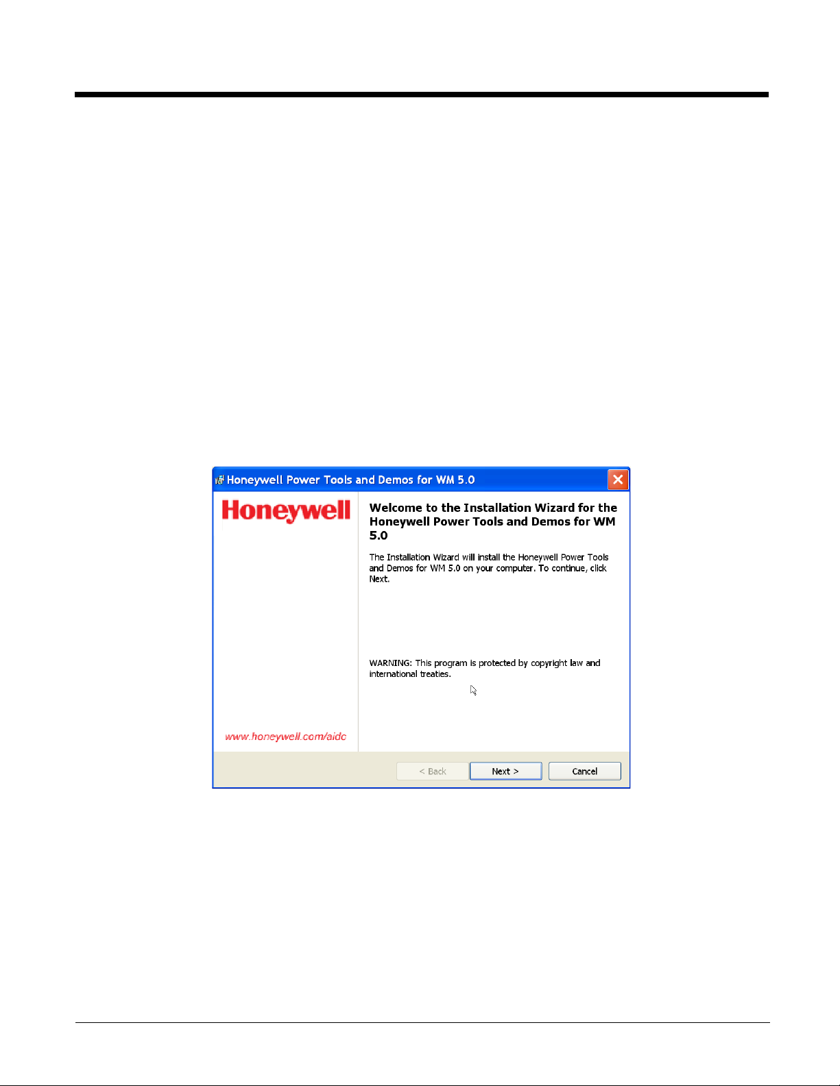
1. Download the new Honeywell Power Tools and Demos for WM 5.0 Setup rx.xx.exe to the
Program Files folder on the workstation.
2. Click the Honeywell Power Tools and Demos for WM 5.0 Setup rx.xx.exe to install.
An active Microsoft® ActiveSync® connection between a host workstation and the terminal.
1 - 6
Page 13
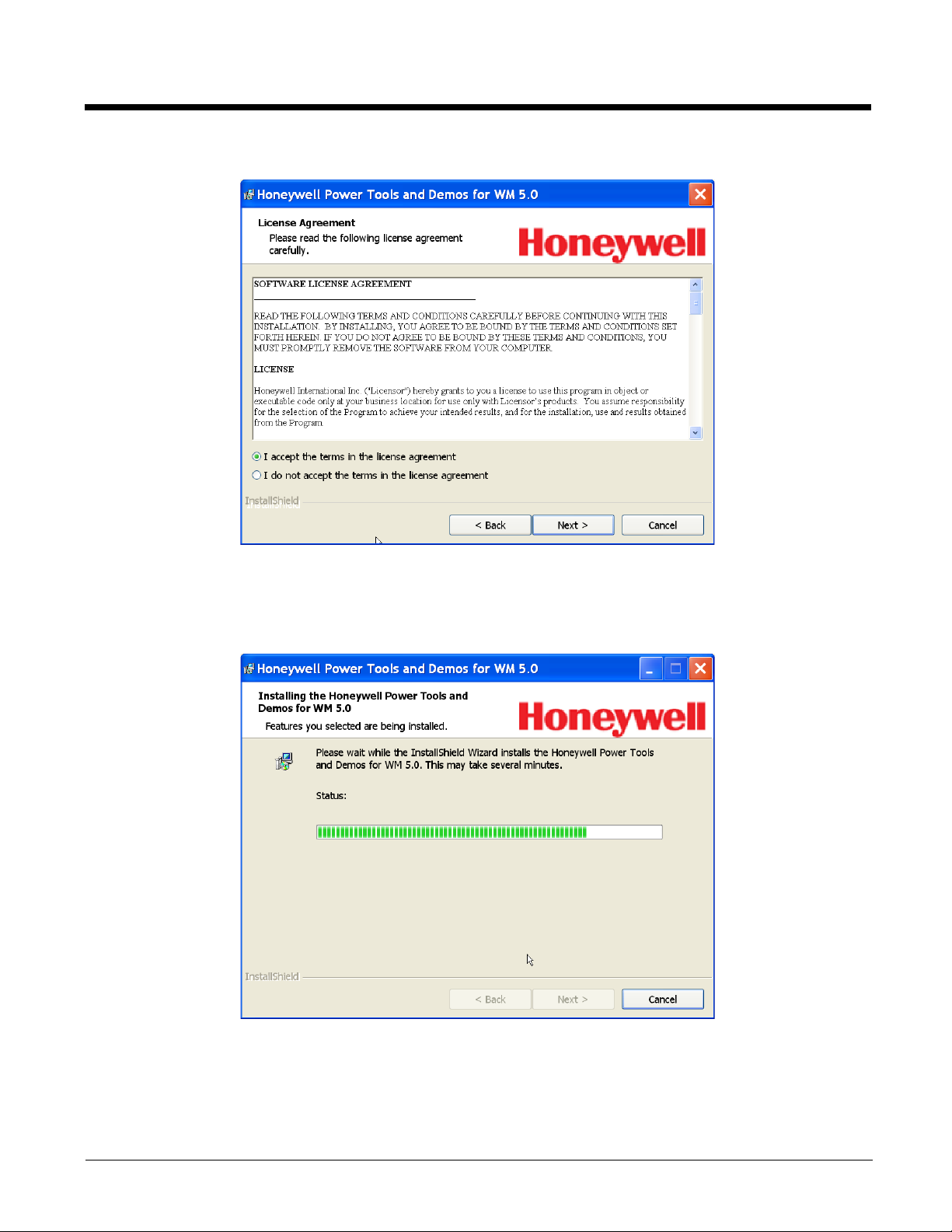
3. Click Next.
4. If you accept the terms of the license agreement, select I accept the terms… click Next.
5. Read the description on the screen and click Install.
6. On the next screen, click Install and program begins installing.
7. When the installation is complete, click Finish.
1 - 7
Page 14
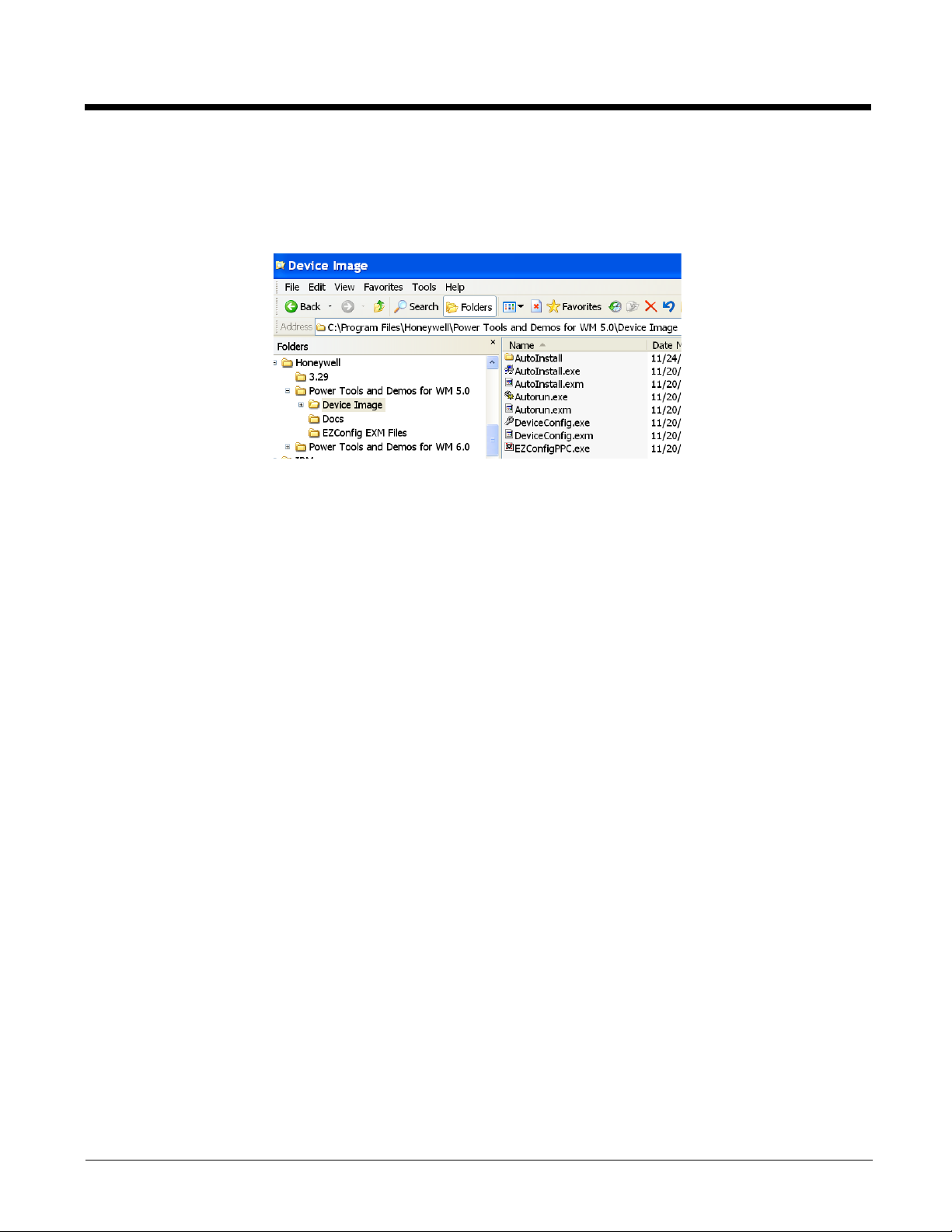
Dolphin Power Tools and Demos Folder on the Workstation
After installation on the workstation is complete, the upgrade files are stored in the C:\Program
Files\Honeywell\Power Tools and Demos for WM 5.0\Device Image folder. The Device Image folder
contains a subfolder for each operating system on the Dolphin terminal.
Note: If a Honeywell folder does not already exist in the Program Files folder, the installation creates one.
The Demos and Power Tools folder on the workstation contains three folders:
Folder This folder contains…
DOCS User guides for Demos and Power Tools (including this guide).
EZConfig Editor EZConfig Editor program and sample EXM files.
Device Image Ghost images of the IPSM upgrade. The contents of each subfolder should replace the
contents of the
\IPSM (\Honeywell for 6100/6500) folder on the Dolphin terminal.
1 - 8
Page 15
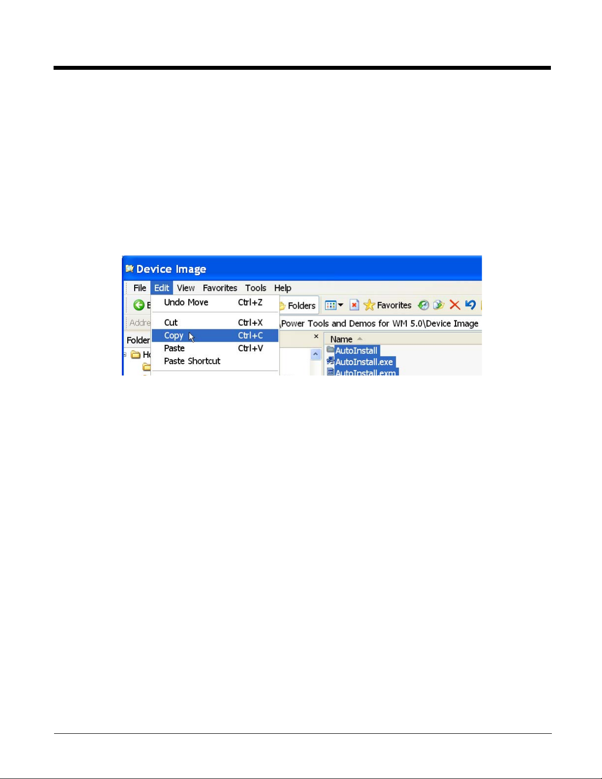
Installing an Upgrade on the Terminal
1. Using the appropriate Dolphin communication peripheral for your series, connect the Dolphin
terminal to the workstation and ensure that the ActiveSync connection is running.
2. On the workstation, open Windows Explorer and navigate to the
\IPSM (\Honeywell for 6100/6500)
folder on the Dolphin terminal.
3. Back up your current \IPSM
4. On the terminal, delete the entire contents of the \IPSM
(\Honeywell for 6100/6500) folder to the workstation.
(\Honeywell for 6100/6500) folder.
5. Tap Start > Programs > Honeywell > Power Tools and Demos for WM 5.0 > Device Image.
6. Copy all items (including the Autoinstall folder).
7. Navigate to the
8. Copy and paste radio CABs, application CAB files, and programs to the \IPSM
6100/6500)
\IPSM (\Honeywell for 6100/6500) folder on the Dolphin terminal and paste.
(\Honeywell for
and \IPSM\Autoinstall (\Honeywell\Autoinstall for 6100/6500) folders.
If you have custom EXM files with settings you want to keep, merge those EXM files with the new
EXM files, and paste them on to the Dolphin terminal.
9. When all the files are pasted, cold boot the terminal.
10. The Power Tools upgrade installs during startup.
1 - 9
Page 16

1 - 10
Page 17

2
EZConfig
Overview
EZConfig is a suite of products that configures Dolphin terminals quickly and efficiently. With the tools in
the EZConfig suite, you can package data on the workstation, then deploy and unpackage that data on
the Dolphin terminal.
Components
There are two main components: EZConfig Editor and EZConfig Client.
EZConfig Editor
Edits and creates configuration and registry documents in the EXM file format for Dolphin terminals. There
are two versions of EZConfig Editor: one for the workstation and one for the terminal.
Both editors:
• Create and modify EXM files–Working with Open EXM Files (see page 2-7)
• Convert INI files to EXM files–Converting Known INI and MNU Files (see page 2-25)
In addition, EZConfig Editor on the workstation
• Generates bar codes from EXM files–Creating Bar Codes (see page 2-19)
For details about the workstation editor, see EZConfig Editor on page 2-2.
For details about the terminal editor, see EZConfig Editor on the Terminal on page 2-27.
EZConfig Client
Decodes the bar codes generated by EZConfig Editor on the workstation.
For details, see EZConfig Client on page 2-31.
Upgrades
EZConfig Editor on the workstation must be installed on the workstation separately from the Power Tools
upgrade. Obtain the Honeywell EZConfig Editor Setup rXX.exe from www.honeywellaidc.com and
install the EXE on the workstation.
All components on the terminal–the EZConfig Editor and EZConfig Client–are installed during Power
Tools and Demos upgrades. For more information, see Upgrading Power Tools on page 1-6.
2 - 1
Page 18

EZConfig Editor
EZConfig Editor creates, edits, and manages EXM files for Dolphin terminals. There is an EZConfig Editor
on the workstation and an EZConfig Editor on the terminal. In the workstation editor, EXM files are edited,
saved, then transferred to the terminal. In the terminal editor, EXM files are edited and saved right on the
terminal; see EZConfig Editor on the Terminal (page 2-27).
EXM Files
The EXM file format is an XML format customized for Dolphin terminals that are comprised of sections
that sometimes contain child sections and keys. Keys contain the values that configure the terminal.
The EXM file format supports a multi-level, hierarchical, tree structure. The terminal reads the highest
level section first and then reads the key values in each section.
EXM files replace INI files for Power Tools and terminal configuration settings. If both an INI file and an
EXM file are present for the same application, the terminal defaults to the EXM file and a warning
message appears at startup. Remove the INI file from the terminal to avoid this warning message.
Types of Configuration Files
There are two types of configuration files in the EXM file format:
Configuration documents Program and configure the terminal; see Opening EXM Files on page 2-6.
Registry documents Update and modify the registry; see Registry Documents (page 2-16).
Sample EXM Files
After you install the new build on the workstation, default EXM files are stored in the C:\Program
Files\Honeywell\Power Tools and Demos for WM 5.0\EZConfig EXM Files folder.
Use these files as templates to create new EXM files.
2 - 2
Page 19
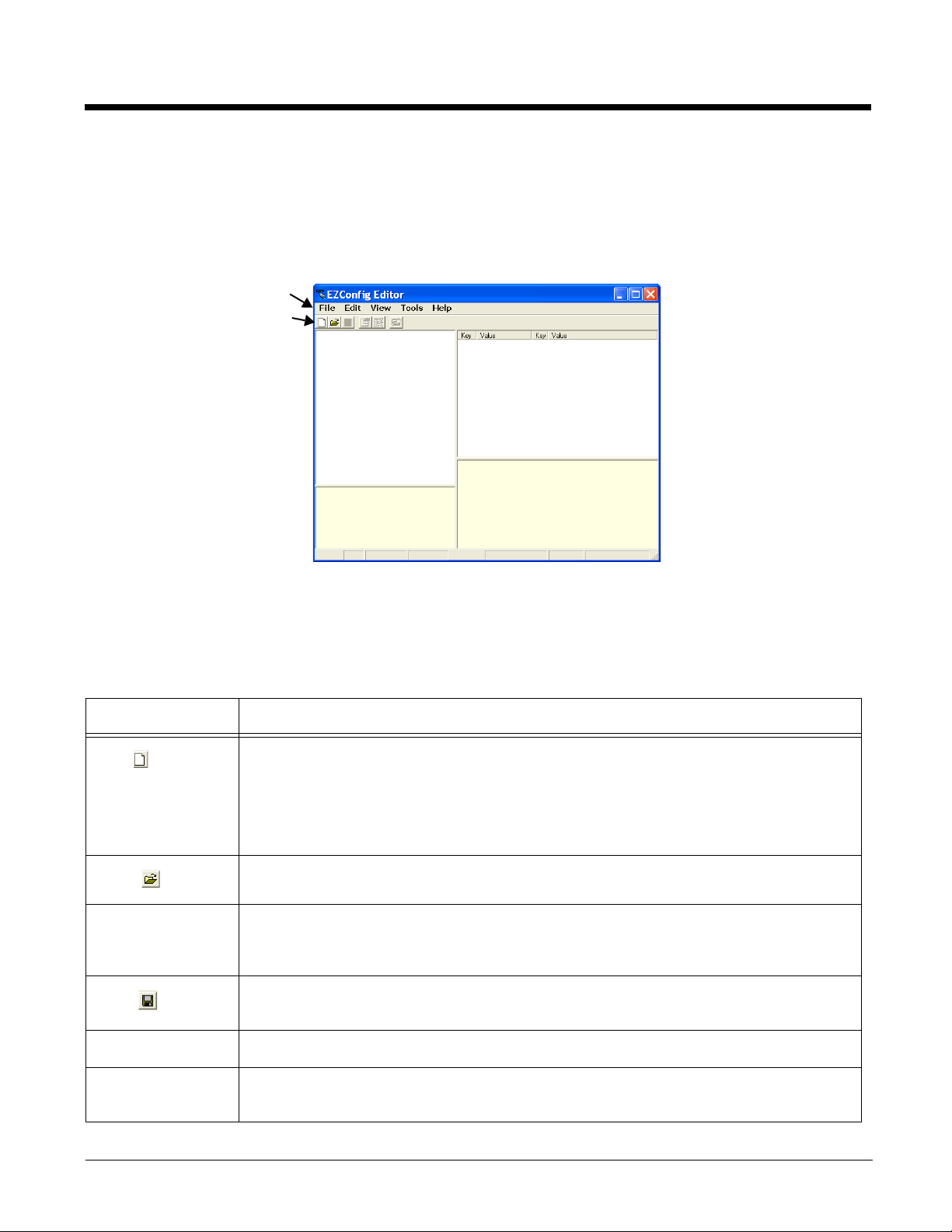
Opening EZConfig Editor on the Workstation
Menu
Toolbar
After you complete installation, EZConfig Editor is available on the workstation from the Start menu.
On Windows Mobile-based devices, click Start > Programs > Honeywell > EZConfig Editor >
EZConfig Editor.
On the Dolphin 7600, click Start > Programs > Power Tools > EZConfig Utilities > EZConfig Editor.
Menu and Toolbar Options
The menu and toolbar at the top of the window contains many options.
File Menu
Menu Item Description
New
Open
Open from Device Opens an EXM file located on the terminal. The location of the file appears in the title bar
Save
Save As Saves the open file with a new name to the location you select on the workstation.
Save to Device As Saves an open file to the terminal; see Saving to the Device on page 2-13.
Creates a new document. There are two options:
• Configuration Document - Creates a configuration file;
Creating New Configuration Documents (page 2-14).
• Registry Document - Creates a registry file in the EXM file format;
Registry Documents (page 2-16).
Opens an EXM file located on the workstation.
with the word “[Remote]” to identify that the open file is located on the terminal.
Note: Requires an ActiveSync connection between the workstation and the terminal.
Saves the open file to the location you select on the workstation.
This option is disabled for new and imported files; use Save As instead.
Note: Requires an ActiveSync connection between the workstation and the terminal.
2 - 3
Page 20
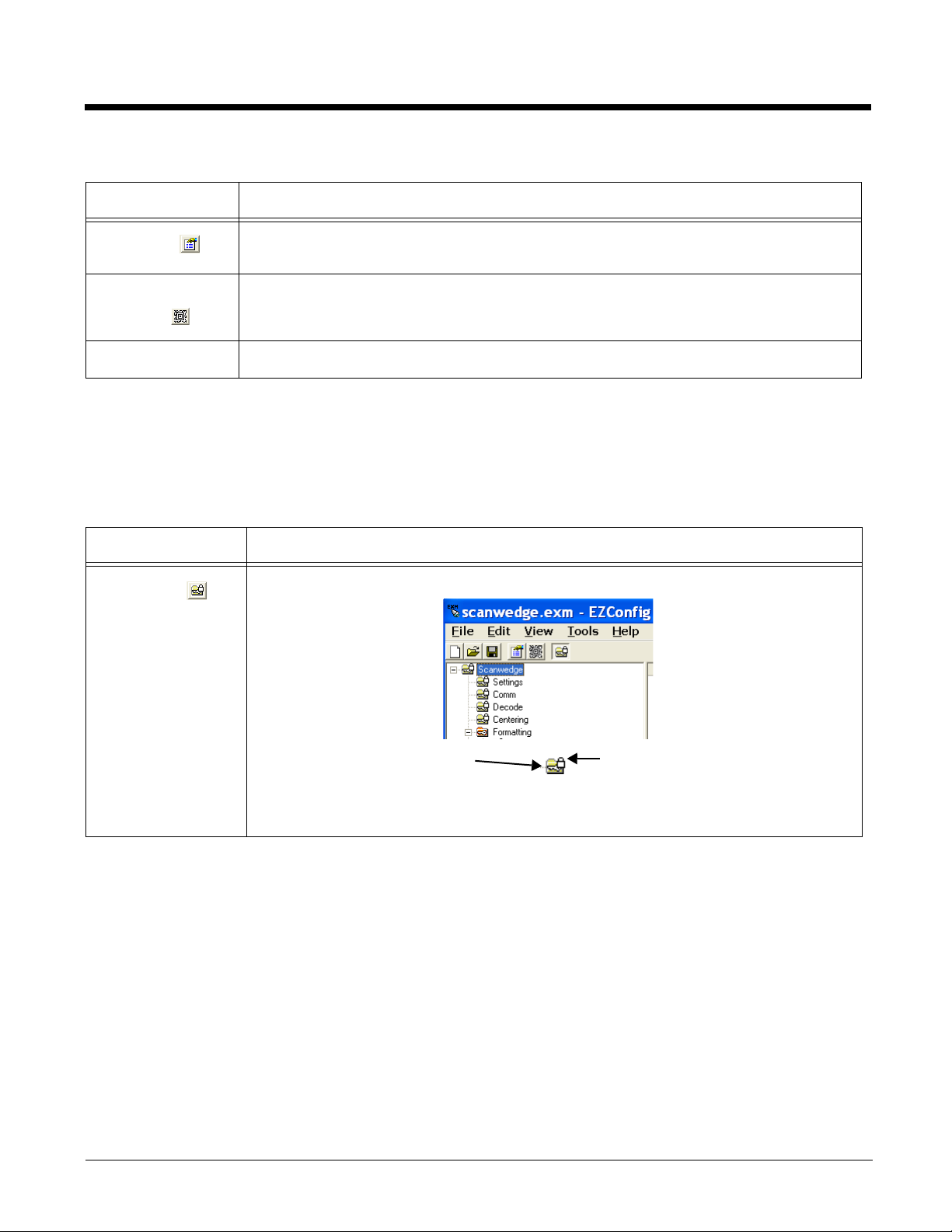
File Menu
The lock icon means the section’s
subsections are locked.
The key icon means that the
section’s keys are locked.
Menu Item Description
Properties
Create EZConfig
Bar Code
Exit Closes EZConfig Editor.
Associates the EXM file with an application on the terminal; see Associating Applications
on page 2-15.
Embeds the open EXM file in an Aztec bar code; see Generating Bar Codes on page 2-
20.
Edit Menu
For Section Edit menu options, see Working with Sections on page 2-7.
For Key Edit menu options, see Working with Keys on page 2-11.
View Menu
Menu Item Description
View Locks
Displays an icon over locked sections. For example,
2 - 4
Information about locks on subsections and keys also appears in the Status Bar (see
page 2-7).
Page 21

Tool s Menu
Menu Item Description
Simplify Document
Note: You cannot
Simplifies the EXM file, which makes it smaller.
Simplifying
permanently removes
undo this
action!
Because the following menu items execute commands on the terminal, there must be an ActiveSync connection
between the workstation and the terminal.
Launch Associated
Application
• Disabled sections and keys
• Descriptions
• Bar code settings
When you create a bar code, you can simplify the file embedded in the bar code without
affecting the open EXM file. This reduces the size of the bar code package yet keeps the
disabled sections, descriptions, and bar code settings in the open EXM file for future
reference.
For more information, see Simplified (page 2-21) on the Advanced Tab (see page 2-21).
If the open EXM file is associated with an application on the terminal, this item is active
and launches the associated application on the terminal.
Note: You would use this option after saving the EXM file to the terminal; see Save to
Device As on page 2-3.
*Warm Boot Warm boots the terminal.
*Cold Boot Cold boots the terminal.
*Some settings affect the boot process and these menu items can help you run a test
without switching to the terminal.
Upgrade Remote
INI Files*
Launches the tool that converts existing INI files stored on a device to the EXM file
format. For more details, see Converting Known INI and MNU Files on page 2-25.
Note: Does not apply to the 6100/6500.
2 - 5
Page 22

Opening EXM Files
EZConfig Editor opens EXM files stored on the workstation or the terminal (if an ActiveSync connection
is established).
Opening EXM Files on the Workstation
Click File > Open or the Open toolbar button and select the EXM file.
When you select a known MNU or INI file, EZConfig Editor prompts you to convert the file. When you
select Yes, EZConfig Editor imports the file and converts it to the EXM file format. Then, you can click
File > Save As to save the file with the EXM extension.
You cannot save known INI or MNU files in their original format. For a list of known files, see Known INI
and MNU Files on page 2-25.
The preferred conversion method is to use the batch conversion tool and then make your edits to the new
EXM files. For details, see Converting Known INI and MNU Files on page 2-25.
Opening Remote EXM Files
The workstation and the terminal must be connected via ActiveSync!
EZConfig Editor can open EXM files located on the terminal so that you can make edits to the terminal’s
configuration real-time.
When the terminal and workstation are connected by ActiveSync, click File > Open From Device and the
remote open window opens. (\Honeywell for 6100/6500)
To open, double-tap on a file or select it and click OK.
Note: You can also open EXM files in the editor on the terminal; see EZConfig Editor on the Terminal (page 2-27).
2 - 6
Page 23
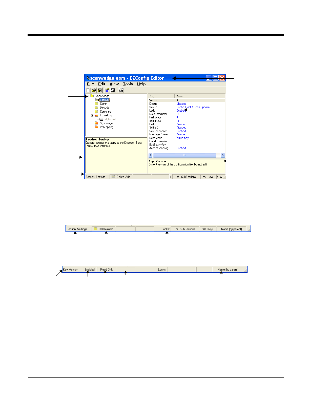
Working with Open EXM Files
Displays the root node
and sections.
Select a section and the
details appear in the
other portions of the
window.
The folders appear in
different colors to
indicate their status.
Displays the section
name and description.
Displays the keys in the
selected section.
Text that appears in blue
can be edited.
Displays the selected
key’s name and
description.
Displays the file name.
If the file is on the
terminal, the title bar
displays the remote
path.
Status Bar
Section Name Merge Mode Locks on subsections and keys
Key Name
Enabled or
Disabled
Read Only Encrypted
Key locked by
section
Whether you open an EXM or INI file, EZConfig Editor displays the content in four different sections of
the window.
Status Bar
The Status Bar appears at the bottom of the window and displays information about selected sections and
keys.
Selected Section
See Section Locks on page 2-9.
Selected Key
See Key Types on page 2-13.
Working with Sections
The EXM file format supports a multi-level tree structure. The section tree appears in the top left quadrant
of the window. The root node identifies the EXM file and “Root” appears in the description.
Sections have a Name and Description and contain keys that appear in the upper right quadrant when
you select the section name. Select a section by clicking on it. You can select only one section at a time.
2 - 7
Page 24
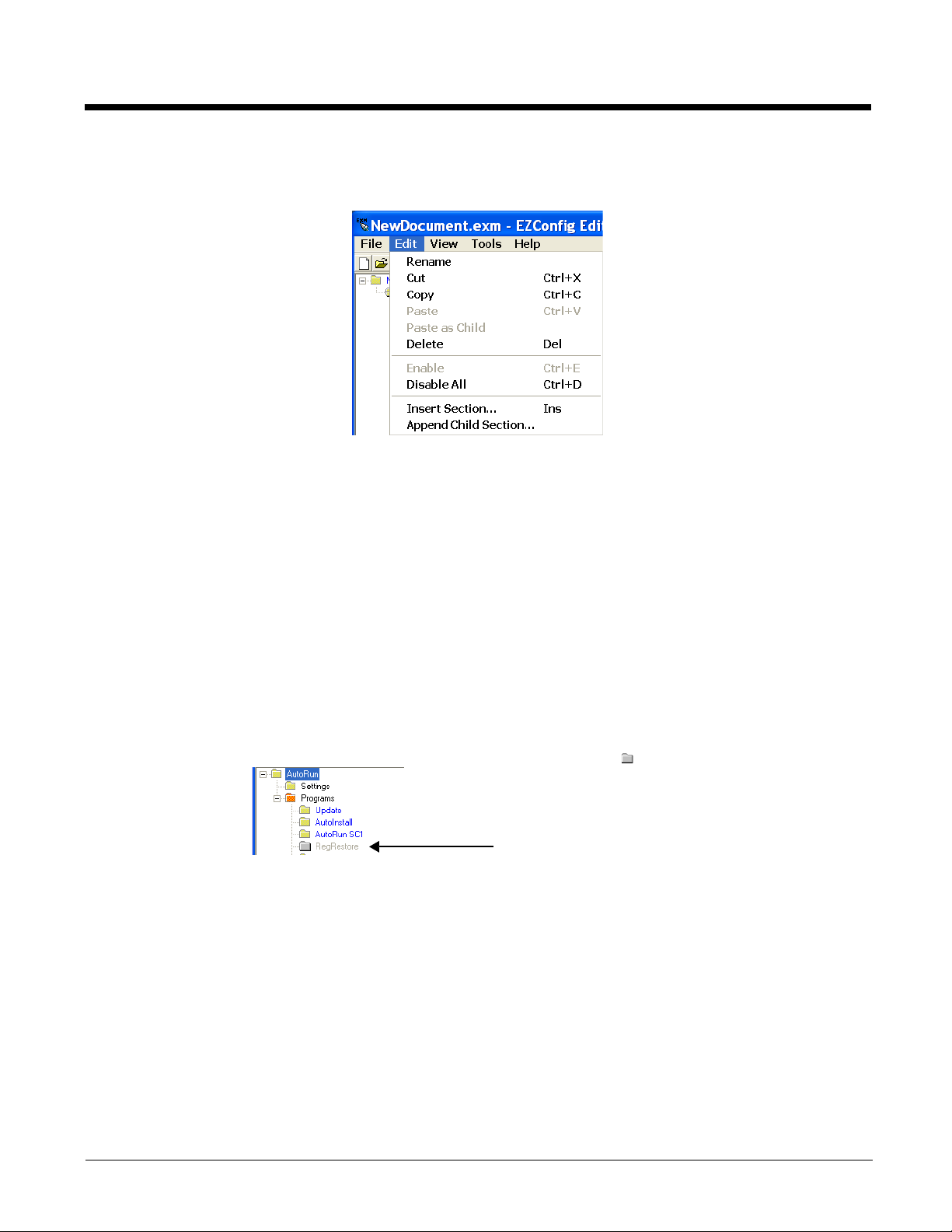
Edit Menu Options
Select a section click Edit to see the available options.
Rename Activates the section name so that you can rename the section.
Note: You cannot modify the name if the section is locked; see Section Locks (page 2-9).
Cut Cuts a selected section.
Copy Copies a selected section.
Paste Pastes the section that was just cut or copied at the same level as the selected section.
Paste as Child Pastes the section that was just cut or copied as a child of the selected section.
Note: You can cut, copy and paste sections within an EXM file or across EXM files.
Delete Deletes a selected section.
Note: Because you cannot undo a delete, consider disabling rather than deleting.
Enable Sections are enabled by default. This menu item enables sections that have been disabled
prior. You can enable a section only if its parent section is enabled. To enable all the keys
inside a section you are enabling, SHIFT + right-click and select
Disable All Sections are enabled by default. This menu item disables sections and all of its keys.
Disabled sections remain in the file with a gray folder .
If you disable a section that has child sections, all of its child sections (and the child section
keys) are disabled automatically. The child section folders are also in gray.
When reading the EXM file, the terminal behaves as though disabled sections are not there
and moves on to read the next enabled section.
Disabled sections can be removed from the EXM file permanently using the Simplify
Document (see page 2-5) option. If you want to keep disabled sections in the EXM file on
the workstation but not in the file deployed to the terminal, use the Simplified option (see
page 2-21) when creating the bar code.
Insert Section This menu item inserts a new section. You can also press the Insert key (INS).
Append Child Section This menu item adds a new child section to a selected section. The new child section is
inserted below the previous section.
Enable All.
2 - 8
Page 25
Modifying Section Names
To change a section name, double-click on the folder and type in the new name or select Rename on the
Edit menu. Type in the new name and press ENTER.
Note: You cannot modify the name if the section is locked or disabled; see Section Locks (page 2-9).
Modifying Section Descriptions
Descriptions are not required to process key values but do help document the EXM file and often contain
valuable information. If you want to modify a section description, select the section, click inside the section
description, and begin typing. You cannot modify descriptions of locked sections.
Moving Sections
To move sections within an EXM file, use the drag and drop method. By default, sections are dropped at
the same level in the tree.
For additional functionality when dragging and dropping, press and hold:
• ALT to drop a section as a child section.
• CTRL to copy a section and drop the copy at the same level in the tree.
• CTRL + ALT to copy a section and drop the copy as a child section.
Note: You can select only one section at a time; you cannot use SHIFT+Click or CTRL+Click to select more than
one section.
To move sections between EXM files, open two instances of EZConfig Editor and drag and drop sections
between them. When dragging, a copy of the section is dragged to the new file. When dropping, drop the
section directly on top of the section you want it to be a child section of.
Note: To drop the first section into a new file, press and hold the ALT key and drop the section on the root node. (All
sections must be child sections of the root node.)
Section Locks
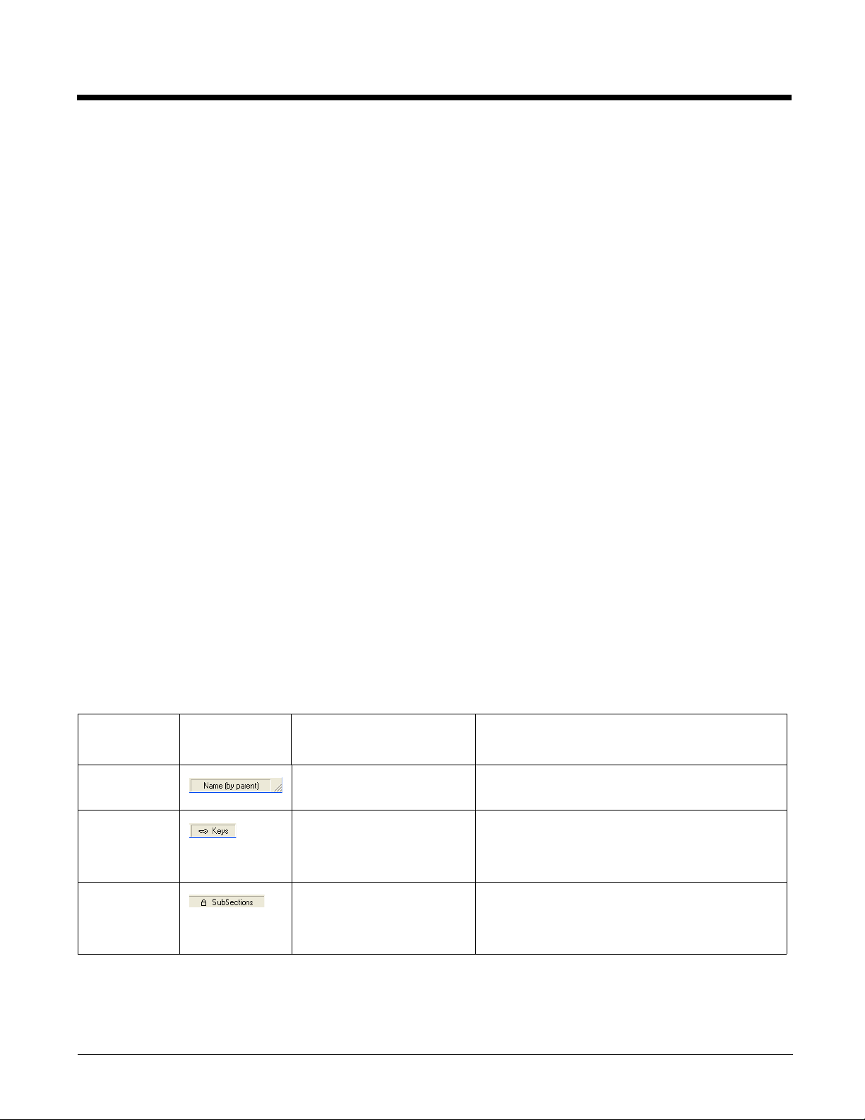
There are different types of locks on sections. The status bar indicates what type of lock is applied to a
selected section.
Lock Type Status Bar
Indicator
Name Lock The section name is
Key Lock All keys are locked.
Subsection
Lock
Note: All locks are applied to each individual section and are not recursive. Only text that appears in blue can be
modified.
Description Effect
• Section Name and Description cannot be
locked.
All immediate subsections
are locked.
modified.
• Key Names and Descriptions cannot be
modified.
• Keys cannot be added, moved, or deleted
within the section.
• Immediate subsection Names and
Descriptions cannot be modified.
• Immediate subsections cannot be added,
moved, or deleted.
2 - 9
Page 26
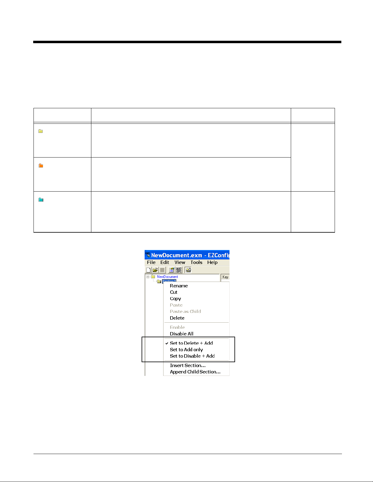
Section-Level Merge Modes
EXM files ship with section-level merge modes already defined according to section content. Merge
modes determine how section information is handled when an updated EXM file is deployed to the
terminal where an existing version of that EXM file is stored.
Merge modes are indicated by folder icons and in the Status bar.
Mode Description Merge Effect
Delete + Add Deletes non-common children elements (i.e., subsections, and keys) in
the target file, then adds the new information from the bar code.
Basically, the new section replaces the old section.
This is the default merge mode for new sections.
Disable +
Add
Add Only Adds new information (sections and keys) to the existing section. If this
Disables non-common children elements (i.e., subsections, and keys) in
the target file, then adds the new information from the bar code.
Note: Disabled sections and keys removed from the simplified bar code
end up as disabled in the target file.
is a brand new section, the new section is added to the existing EXM
file.
Note: Disabled sections removed from the simplified bar code are not
modified in the target file.
To change section-level merge modes, select a section and right click.
Exclusive
Inclusive
The folder colors change immediately after selection.
2 - 10
Page 27
Working with Keys
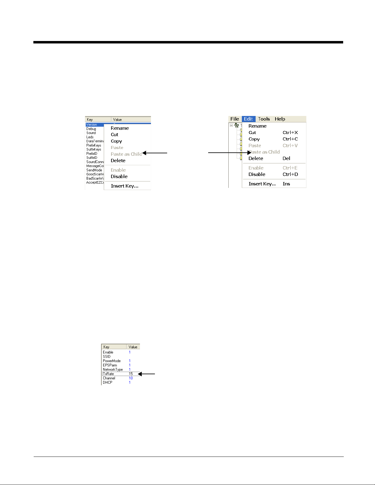
The same options
appear on both
menus.
Keys have a Name, a Description, and a Value and reside inside sections. For specific key values, consult
the chapters of this user’s guide that describe the EXM file you’re attempting to edit.
Edit Menu Options
Select a key and right-click or click Edit to see the available options.
Rename Activates the key name so that you can rename the key.
Note: Rename is disabled if the key is locked or disabled; see Key Types (page 2-13).
Cut Cuts a selected key.
Copy Copies a selected key.
Paste Disabled; keys can be pasted only as children of a section.
Paste as Child Pastes the key just cut or copied in the selected section. Keys are not multi-level; all keys
paste at the same level within a section.
Note: You can cut, copy and paste keys within an EXM file or across EXM files.
Delete Deletes a selected key.
Note: You cannot undo a delete; you might want to consider disabling rather than deleting.
Enable Enables keys that were disabled. When a key is enabled, the client application can read
and apply its value. When you enable a key, make sure to specify a value for that key; do
not leave it blank.
Note: To enable a key, its parent section must be enabled.
Disable Disables keys. Enabled keys have key values in blue. Disabled keys have key values in
black.
The terminal does not read disabled keys and disabled keys are removed if the file is
simplified; see Simplify Document (page 2-5).
Because many key values are 1 for enable and 0 for disable, remember that disabling
a key means that the terminal behaves as if the key is not there when reading the file,
NOT that the key’s value is set to disabled. The terminal simply moves on to read the
next enabled key.
Insert New Key This menu item inserts a new key above the selected key.
Note: You can also press the Insert key (INS).
2 - 11
Page 28

Modifying Key Names
To modify key names, double-click on the key name or select Rename on the Edit menu. Type in the new
name and press ENTER or TAB.
Note: You cannot modify the description if the key is locked; see Key Types (page 2-13). Only text that appears in
blue can be modified.
Modifying Key Values
You can modify a key value only if its text appears in blue. In that case, double-click on the value or select
the key and press ENTER. Type in the new value and press ENTER or TAB to save.
Modifying Key Descriptions
Descriptions are not required to process key values but do help document the EXM file and often contain
valuable information. To modify a key’s description, click on the key, then click in the key description area.
When the cursor is active, you can type in the text.
Note: You cannot modify the description if the key is locked; see Key Types (page 2-13).
Moving Keys
To move keys within an EXM file, use the drag and drop method. Press and hold the CTRL key to drag
and drop a copy of the key to the new location.
Note: You cannot move a key if it is locked by its section.
To move keys between EXM files, open two instances of EZConfig Editor and drag and drop keys
between them. When you select the key and drag, a copy of the key is dragged to the new file. In the new
file, drop the key in the key area of a selected section; keys are always dropped at the same level within
a section.
2 - 12
Page 29
Key Types
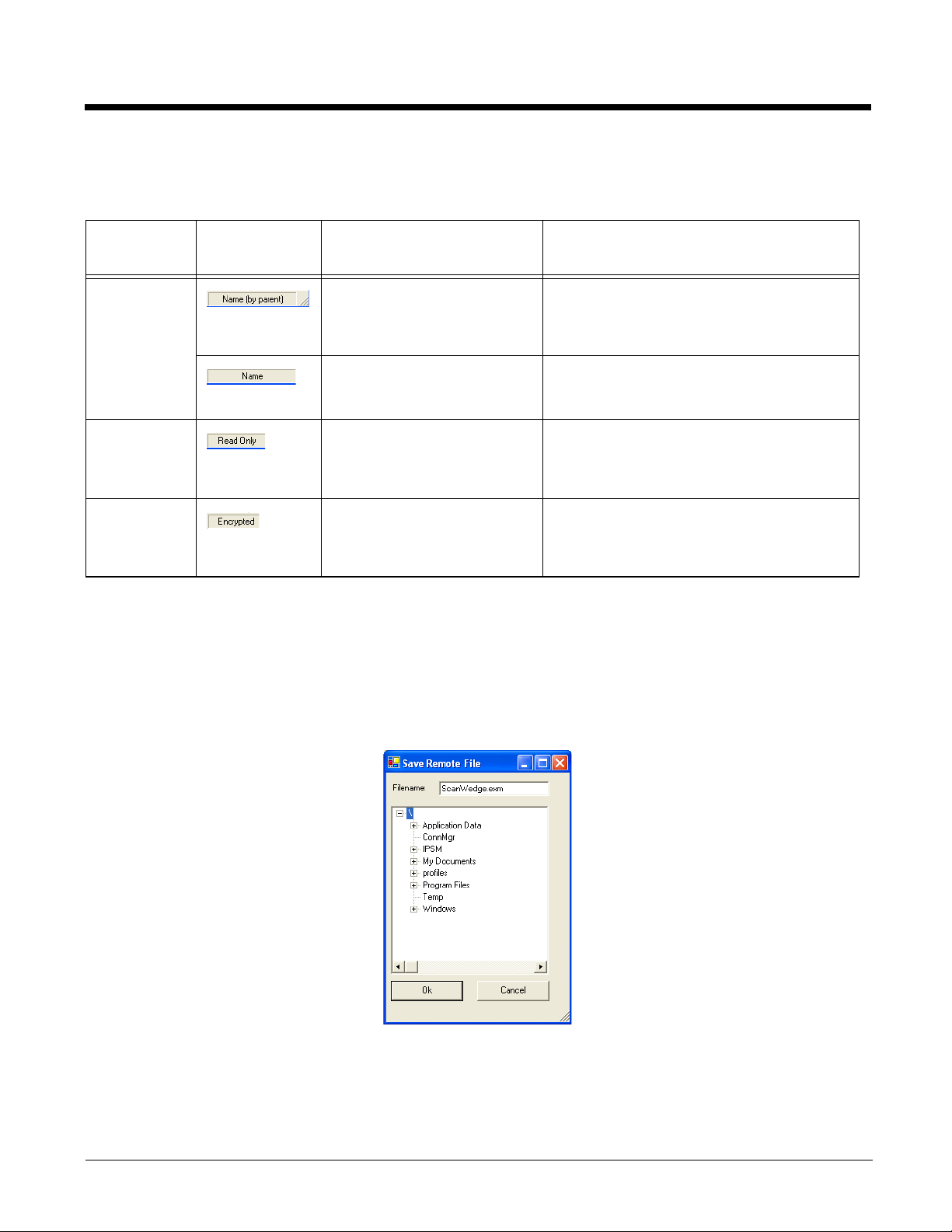
When a key is selected, its properties display in the Status bar.
Lock Type Status Bar
Indicator
Name Lock Keys are locked by the
Read Only Read-only keys cannot be
Encrypted
Note: Locked and Read Only properties are not recursive. Properties are applied to each individual key. Only text
that appears in blue can be modified.
Description Effect
• Name and Description cannot be
section.
The key name is locked
individually.
modified in any way. They
appear in red.
Key’s value appears as
asterisks (*) for added
security.
modified.
• Keys cannot be added, moved, or
deleted within the section.
• Name and Description cannot be
modified.
• These keys can be moved.
• Name, Description, and Value cannot be
modified.
• Keys cannot be added, moved, or
deleted within the section.
Note: Encrypted keys are also stored
encrypted in the EXM file. If you open
the EXM file in a text editor, you won't
see the data as clear text.
Saving to the Device
You can save EXM files directly to the terminal when there is an ActiveSync connection between the
terminal and the workstation. Select File > Save to the Device As and the Save Remote File window
opens.
Select the location on the terminal where you want to store the file and click OK. The file is downloaded
directly to the terminal via ActiveSync.
Note: EXM files for Dolphin Power Tools must be stored in the
\IPSM (\Honeywell
for 6100/6500) folder.
2 - 13
Page 30
Creating New Configuration Documents
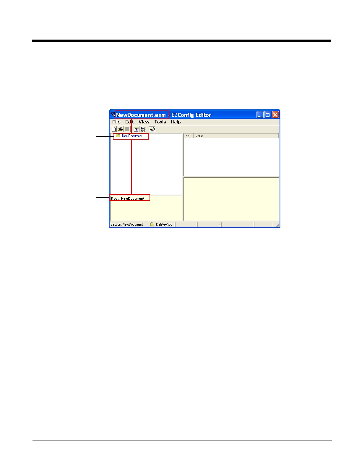
The terminal reads
root node first.
The Description
says “Root” to
indicate that this is
the root section.
To create new EXM files that are configuration documents, you can open an existing EXM file and save
it with a new name or create an EXM file from scratch.
1. Click File > New > Configuration Document. The root node is created and appears as the top level
section. All sections must be at least one level down from the root node. The name of the root node
is always the same as the filename.
Note: You can also create registry documents in the EXM file format. For details, see Registry Documents on page
2-16.
2. To create the first subsection, select the root node, right-click, and select Append Child Section.
Insert Section is disabled because you cannot insert sections at the same level as the root node.
3. Enter a Name and a Description and click OK.
The name is required, the description is optional.
4. To add a new section at the same level, right-click and select Insert Section.
To add a new section one level down, right-click and select Append Child Section.
5. To add keys, select a section, right-click in the key value section, and select Append Key.
6. Enter the Name, Value, and Description and click OK.
The name is required, the description is optional.
7. Continue adding sections and keys.
8. If necessary, associate this EXM file with an application; see Associating Applications (page 2-15).
9. Click File > Save As to save the file.
Save is disabled so that you save the document with a name other than “NewDocument.exm.”
2 - 14
Page 31
Associating Applications
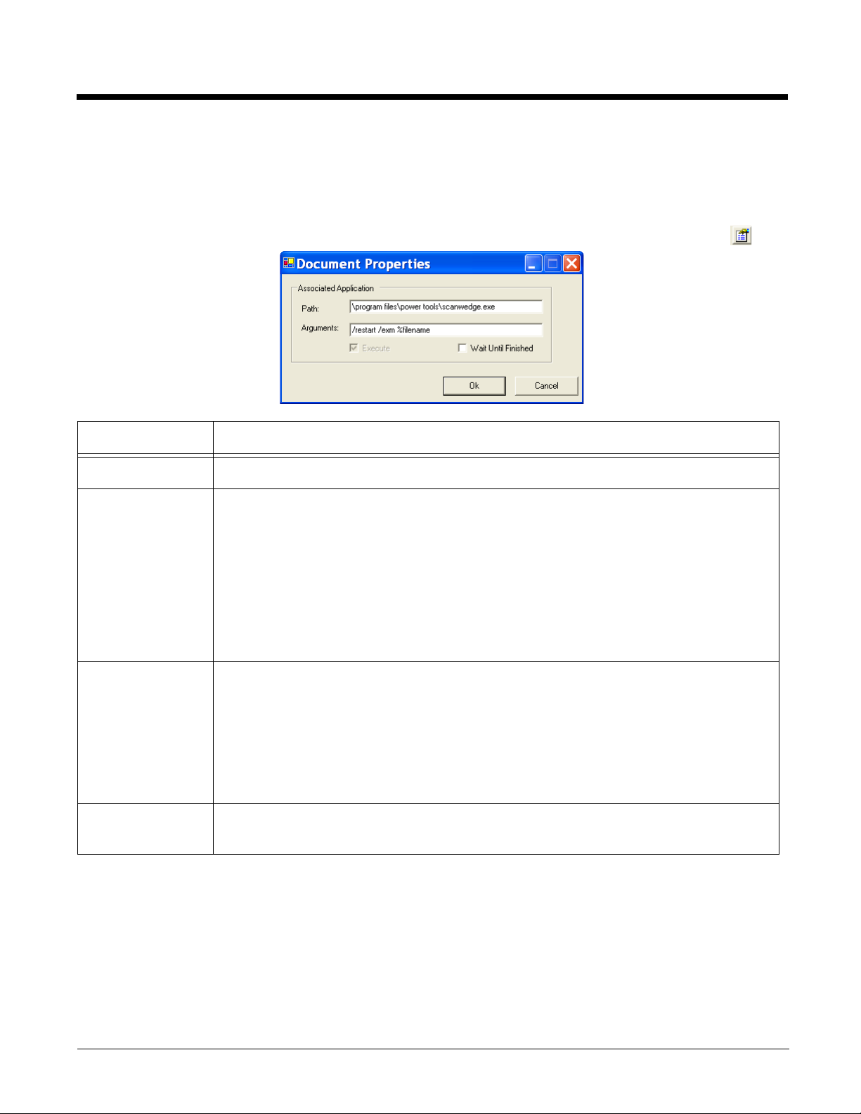
The Properties function associates an EXM file with an application on the terminal. The associated
application launches after EZConfig Client decodes the bar code containing the EXM file. For more
information, see Creating Bar Codes on page 2-19.
While the EXM file is open, click File > Properties or the Document Properties toolbar button .
Field Description
Path Enter the location of the EXE on the terminal.
Arguments Enter the command line argument you want applied when the application launches.
When an application is entered in the Path field, the following command line appears as
the argument:
/exm %filename.
Enter additional command line arguments (see Command Line Arguments on page 2-
34) next to /exm %filename in this field.
“%filename” means that the value immediately after the “%” is variable and the file name
will be replaced with the remote path entered on the Bar Codes tab; for more information,
see Remote Path on page 2-20.
Execute Tells EZConfig Client to launch the application after decoding the bar code. Execute
selects automatically when an application is entered in the Path field.
You cannot de-select Execute for configuration documents.
You can de-select Execute for registry documents; however, EZConfig Client cannot
update the registry unless Execute is selected. For more information, see Default
Application Association (page 2-16).
Wait Until
Finished
Tells EZConfig Client to wait until the associated application is finished processing before
finalizing.
2 - 15
Page 32
Registry Documents
EZConfig Editor creates registry documents in the EXM file format and also opens existing REG files and
converts them to the EXM file format. EZConfig Editor cannot save registry documents in the REG file
format.
Updating the Registry on the Terminal
To update the terminal’s registry, you must
• Create an EXM file that is a registry document–Creating Registry Documents (page 2-16),
• Create a bar code package from that EXM file–Creating Bar Codes (page 2-19), and
• Scan the bar code with the terminal
By default, EZConfig Client on the terminal updates the Windows registry immediately after decoding the
bar code.
Default Application Association
By default, registry documents are associated with EZConfig Client. While a registry document is open,
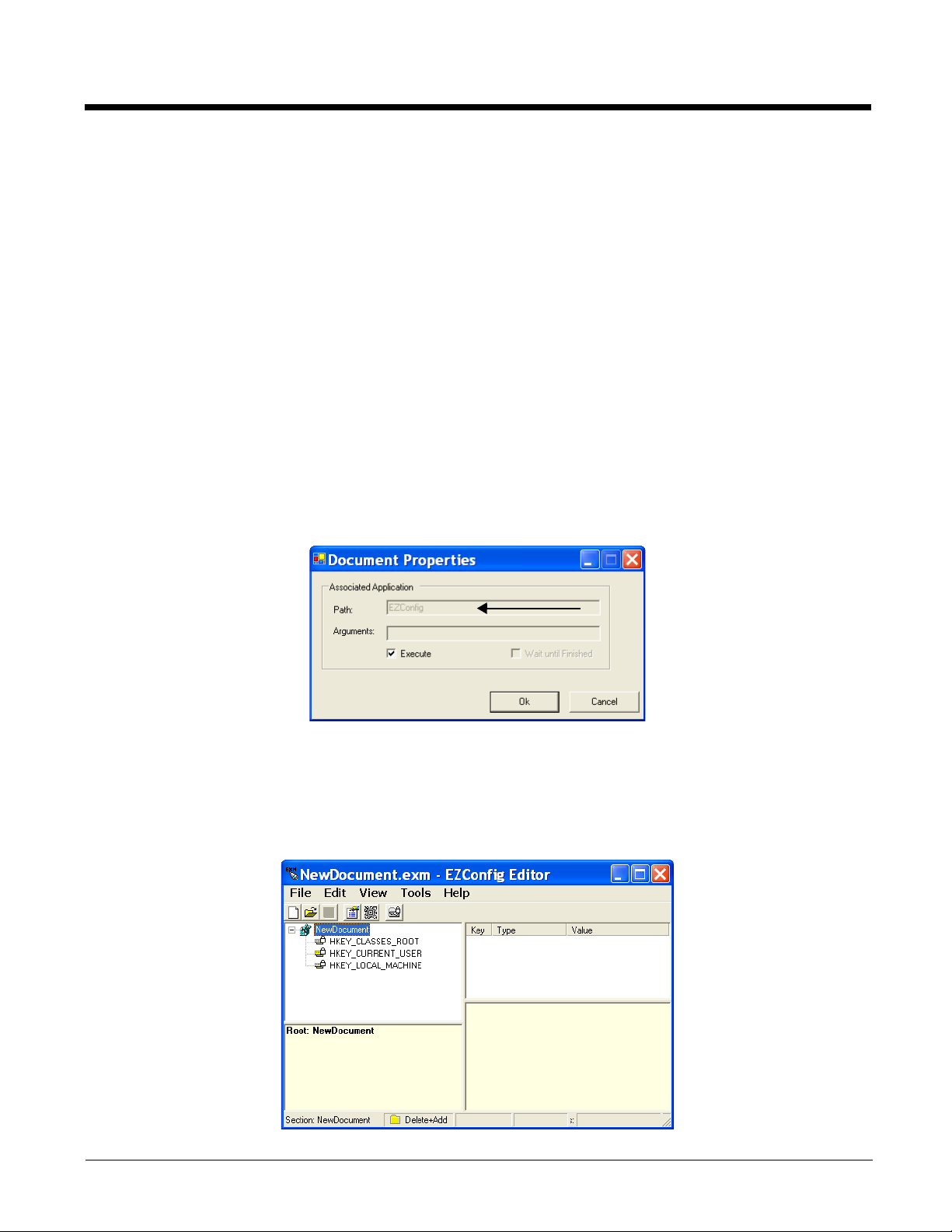
click File > Properties.
Execute must remain selected for EZConfig Client to update the registry after decoding the bar code. If
Execute is not selected, the registry document is deployed after decoding but the registry is not updated.
Creating Registry Documents
1. In EZConfig Editor, click File > New > Registry Document.
2 - 16
Page 33
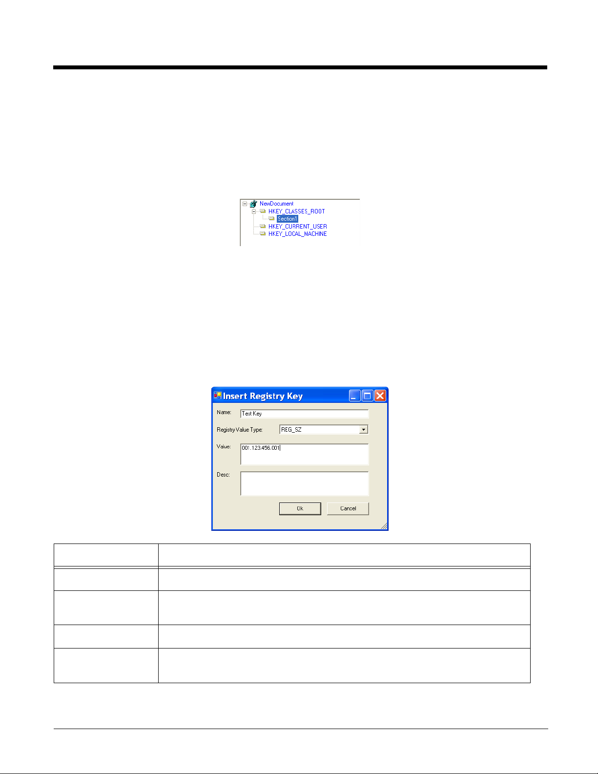
The new document contains the three top-level sections in a registry. These sections are locked and cannot be
changed. You can add subsections to each section and then add keys to those subsections.
2. Click File > Save As.
3. Choose the name and location and click Save.
You cannot save the document as a .reg file; you must save it as an EXM file.
4. To add sections, select one of the registry levels, right-click, and select Append Child Section.
Enter the section information, and click OK.
For more information about adding sections, see Working with Sections on page 2-7.
5. To add keys to the new section, select the section, and right-click in the key value area.
For details, see Adding Registry Keys on page 2-17.
6. Continue adding sections and keys.
7. Save the file.
Adding Registry Keys
To add a key, select a section, and right-click in the key area of the EZConfig Editor window.
Field Description
Name Enter the key’s name.
Registry Value Type Select the registry type from the drop down list. This value appears in the Type
column.
Val ue Enter the key’s value.
Desc Enter a description for the key; descriptions appear in the lower half of the EZConfig
Editor window when the key is selected.
2 - 17
Page 34
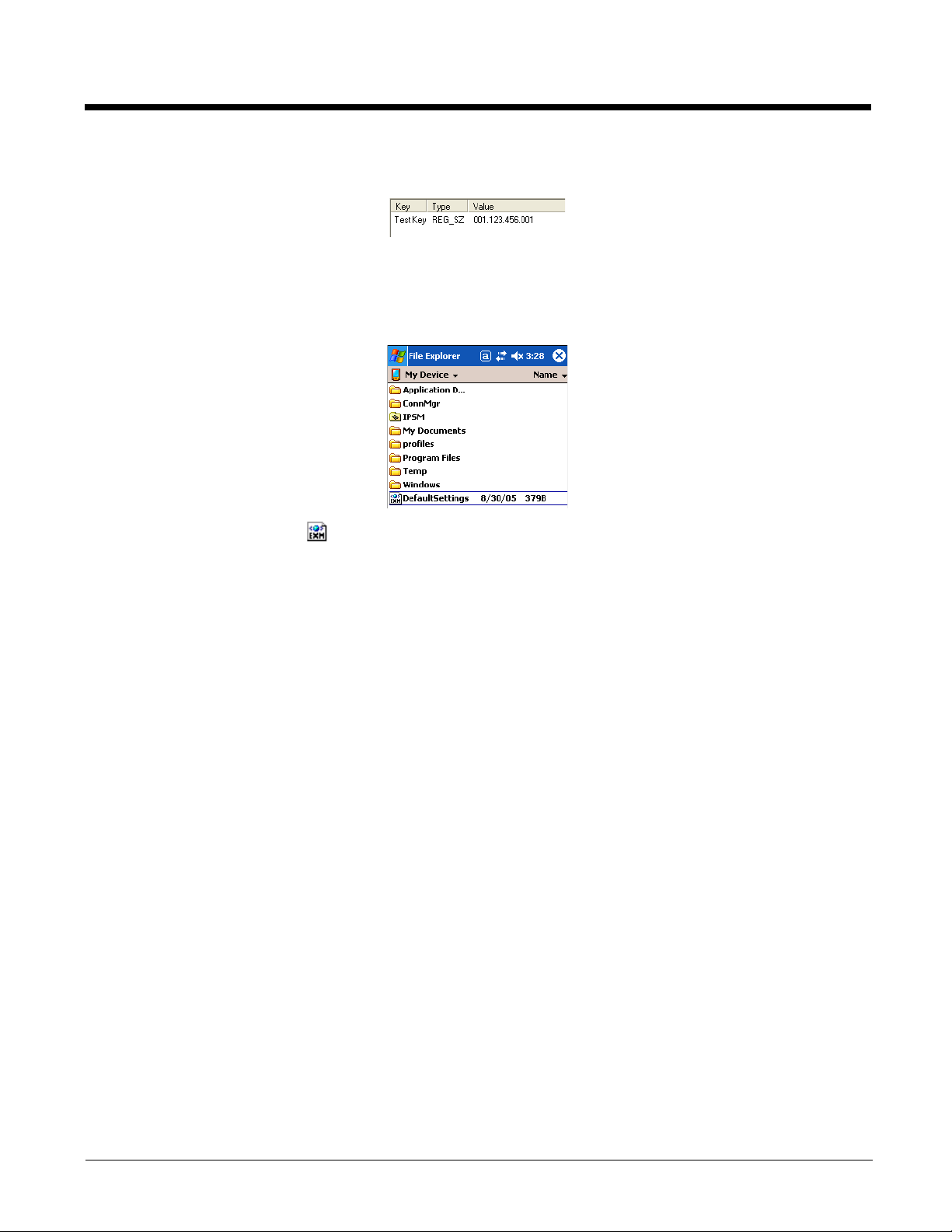
When you click OK to save the key, the data appears in columns in the key area of the EZConfig Editor
window.
Processing Registry Documents on the Terminal
After EZConfig Client updates the registry, the EXM file itself is deployed to the location entered in the
Remote Path (page 2-20) field on the Bar Codes Tab (page 2-20).
Note: EXM files appear with an icon on terminal windows.
If you do not want to store the registry EXM file on the terminal after updating the registry, select the
Temporary (page 2-22) option on the Bar Codes Tab (page 2-20).
Persistent Registry Documents
If you want to update the registry during every cold boot, create a registry document in the EXM format,
save it to the terminal in the
registry settings in the EXM file will load during startup.
Note: Of course, if you want to save a registry file but not load it every startup, simply store the registry EXM file in
the
\IPSM
(\Honeywell for 6100/6500)
\IPSM\Autoinstall (\Honeywell for 6100/6500) folder, and cold boot. The
folder.
2 - 18
Page 35

Creating Bar Codes
EZConfig Editor embeds EXM files in bar codes. The EZConfig Client on the terminal decodes the bar
code and deploys the data. Using bar codes quickly and easily configures Dolphin terminals without an
IrDA, ActiveSync, or network connection to a workstation.
Document Types
EZConfig Editor produces two kinds of EXM files: configuration documents and registry documents. Both
can be embedded in bar codes and processed by EZConfig Client on the terminal.
Configuration Documents
EZConfig Client deploys the EXM file in the terminal. If an EXM file is associated with an
application, EZConfig Client deploys the data to that application for processing; see
Associating Applications on page 2-15.
Note: The DeviceConfig.exm file must be associated with DeviceConfig.exe to be
processed appropriately on the terminal.
Registry Documents EZConfig Client updates the registry immediately without launching another application.
Bar Code Type
EZConfig Editor creates an Aztec bar code; for example, .
Time and Date Stamp
EXM files are stamped with the time and date the moment EZConfig Editor creates the barcode.
Bar Code Size and Number
The amount of data in the EXM file determines how many bar codes are generated and the physical size
of each bar code. More data means more bar codes and larger bar codes.
EZConfig Editor offers four ways to control how many bar codes are produced and adjust the size of each
bar code:
1. Set byte size limits on how much data each bar code can contain—see Max Barcode Size on page
2-22.
2. Split the data across a specified number of bar codes—see # Bar codes to generate on page 2-21.
3. Simplify the EXM file in the bar code—see Simplified on page 2-21.
4. Scale the bar codes on the bar code sheet—see Bar Code Scaling Factor on page 2-23.
Bar Code Sheet
EZConfig Editor produces a bar code sheet that contains the generated bar codes. Bar code sheets can
be printed from a laser printer, copied to the clipboard, and saved as an HTML file; see Printing and
Saving Options on page 2-23.
In addition, individual bar codes can be saved as .tif or .png graphic files that can then be emailed and
printed; see Bar Codes Tab on page 2-20.
2 - 19
Page 36
Generating Bar Codes
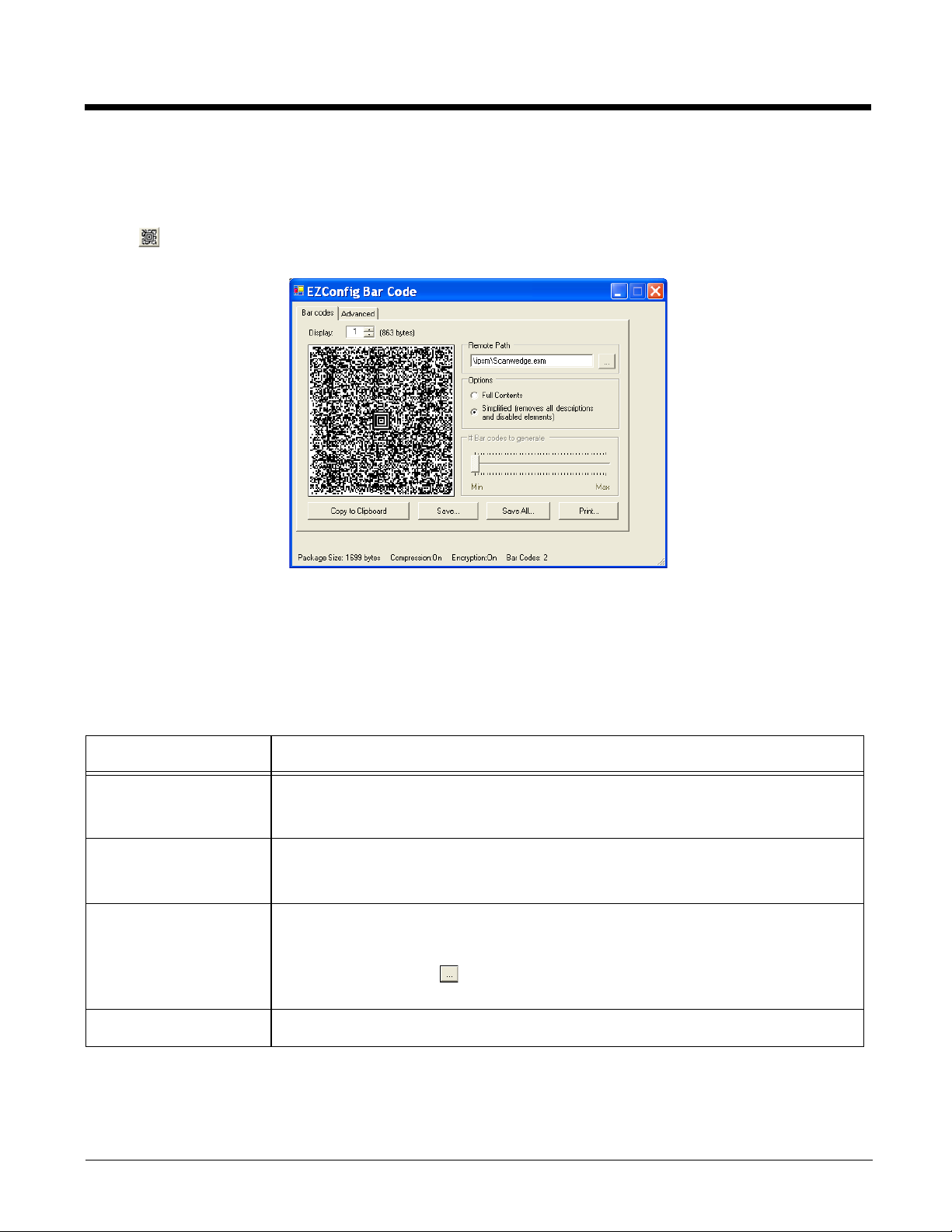
When creating a bar code, EZConfig Editor automatically encrypts and compresses the data in the EXM
file. To generate a bar code, click File > Create EZConfig Bar Code OR the Create Bar Code toolbar
button while the EXM file is open. EZConfig Editor generates a bar code or codes. The Bar Codes tab
window opens displaying the details of the bar code package generated.
The Bar Codes and Advanced tabs offers several processing options.
Note: The number of bar codes produced depends on the amount of data present in the EXM file. The more data
present, the more bar codes generated. You must scan all bar codes to deploy the package!
Bar Codes Tab
The Bar Codes tab previews and customizes generated bar code(s).
Field/Option Description
Display Indicates which bar code is displayed in the preview area; the default is “1,” the first
(___ bytes) Displays the exact byte size of the bar code displayed in the preview area.
Remote Path Type in the location and filename where the EXM file should be deployed on the
Full Contents Includes the full content of the EXM file in the bar code, without simplifying.
bar code in the package. If more than one bar code was generated, you can use the
up and down arrows to scroll through the bar codes.
To ta l Package Size (page 2-23) is displayed at the bottom of the window.
Note: The sum of bar code size is typically larger than the package size.
terminal. For instance,
\ipsm\deviceconfig.exm (\Honeywell for 6100/6500)
Tap the browse button to navigate to the location on the terminal. Your
ActiveSync connection must be active.
2 - 20
Page 37
Field/Option Description
Simplified Simplified is selected by default. This option simplifies the EXM file in the bar code,
which removes disabled sections, description information, and bar code settings (if
any), which decreases the size of the bar code. The open EXM file is
The differences in total package size are displayed in the Package Size (page 2-23)
field. Individual bar code size can be seen in the Display (page 2-20) field.
not simplified.
# Bar codes to
generate
Copy to Clipboard Copies the bar code displayed in the preview area to the clipboard.
Save Saves the bar code displayed in the preview area as a graphic file as a .png or .tiff.
Save All Saves all bar codes in the package as individual graphic files.
Print Opens the printing window where you can select print options and print the bar code
This is active only if the Always use minimum # bar codes (see page 2-22) is
selected. When this slider is active, you can move the slider toward minimum or
maximum to change the number of bar codes generated. As you move the slider,
you’ll see the number of bar codes in the counter at the bottom of the window
and you’ll notice the graphic of the bar code in the preview area change.
Use this option to paste the bar code into another application.
By default, the name of the graphic file is the same as the name of the open EXM
file. You can enter a different name when saving.
By default, the graphic files are saved with the same name as the open EXM file with
a number at the end to distinguish the individual graphic files from each other.
package. For details, see Printing and Saving Options on page 2-23.
not
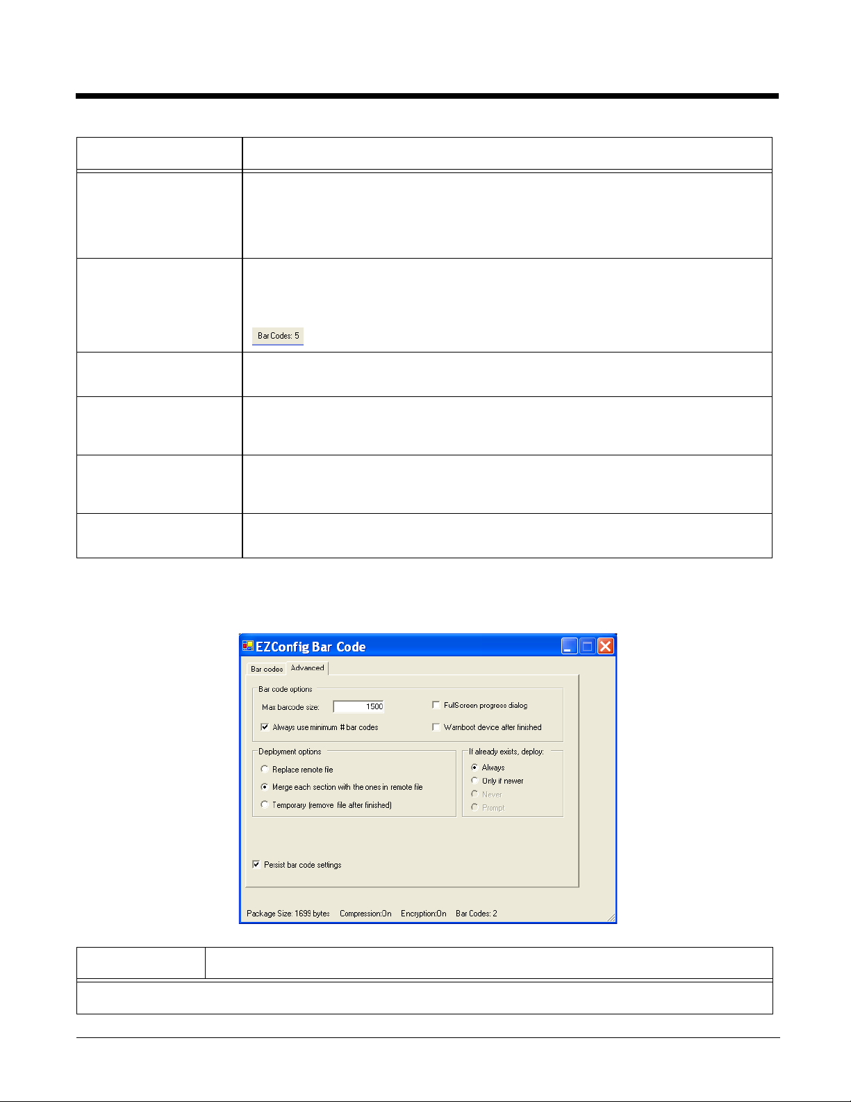
Advanced Tab
The Options tab contains settings that tell EZConfig Client how to process the EXM file on the terminal.
Field Description
Bar Code Options
2 - 21
Page 38

Field Description
Max Barcode
Size
Always use
minimum # bar
codes
Full screen
progress dialog
Warm boot after
finished
Set the maximum amount of data (in bytes) one bar code can contain. The lower the
number of bytes, the smaller the bar code. Bar code size is displayed to the right of the
Display (page 2-20) field. The total number of bar codes created is displayed at the bottom
of the window; see Bar Codes (page 2-23).
This option is selected by default. It calibrates the data so that the minimum number of bar
codes are used. When this option is selected, the number of bar codes slider on the Bar
Codes tab is disabled.
This option runs the deployment progress dialog box on the terminal in full screen mode
so that the user cannot open another application while the bar codes are being deployed
on the terminal.
This option automatically launches a warm boot on the terminal after the bar code is
deployed. Use this options with EXM files that contain application information requiring a
warm boot to take effect, such as registry settings.
Deployment Options–These options determine how to deploy the EXM file embedded in the bar
code. For each deployment option selected, there are corresponding overwrite options under If
already exists, deploy:.
Replace remote
file
Replaces the existing file; no section-level merge modes are applied.
If already exists, deploy:
• Always—Select to always replace the existing file.
•
Only if newer—Select to replace the existing file only if the file in the bar code is newer
than the existing.
•
Never—Do not deploy the new file; this preserves the existing file.
•
Prompt—EZConfig Client asks the user if they want to overwrite the existing file during
deployment.
Merge each
section…
(Default
selection)
Tempora ry Deploys the EXM file temporarily. The settings in the EXM file are applied, but the file does
Persist Bar Code
Settings
Deploys information according to the section-level merge mode settings; see Section-
Level Merge Modes on page 2-10.
If already exists, deploy:
• Always—Select to always use the section-level merge mode settings.
• Only if newer—Select to use the section-level merge mode settings only if the sections
are newer than the existing file.
not remain in the system after EZConfig Client is done.
If the terminal contains a previous EXM file with the same name, the previous EXM file is
preserved.
Stores the settings from the Options, Bar Codes, and Web Page tabs within the EXM file
so that the same bar code settings are applied the next time a bar code is created. This
increases the size of both the EXM file and the bar code(s).
If the Simplify option is selected, bar code setting information is not included in the bar
code but remains in the open EXM file.
2 - 22
Page 39
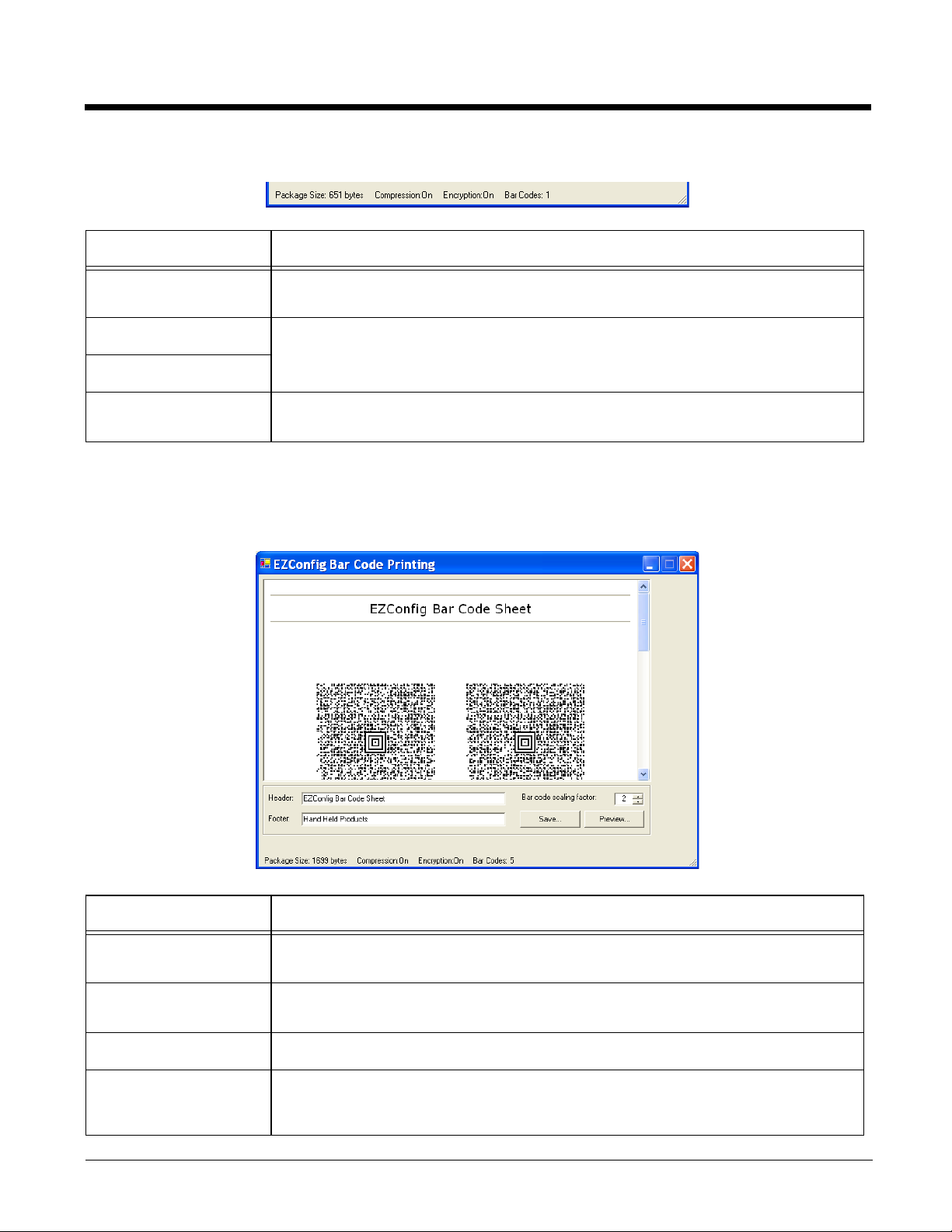
Information at the Bottom of Tab Windows
Field Description
Package Size Displays the total size of the bar code package. This number changes with
simplifying.
Compression On Notifies you that compression and encryption are both on.
Compression and encryption are always on by default. EZConfig Editor uses 128-bit
Encryption On
Bar Codes Displays the total number of bar codes generated. This number changes as you
encryption automatically.
move the slider on the Bar Codes tab.
Printing and Saving Options
On the Bar Codes tab, when you click Print, a bar code printing window opens offering you a number of
printing options.
Field/Option Description
Preview Area This is the largest section of the tab window and displays a preview of the bar code
sheet. Use the scroll bars to see all the bar codes.
Header Type in a custom header for the page. “EZConfig Bar Code Sheet” is the default
header.
Footer Type in a custom footer for the page. “Hand Held Products” is the default footer.
Bar Code Scaling
Factor
Adjusts the size of each bar code by scaling all of them up or down, which
determines how many bar codes can fit on each page. This does not change the
amount of data in each bar code, just the size of the bar code on the page.
2 - 23
Page 40
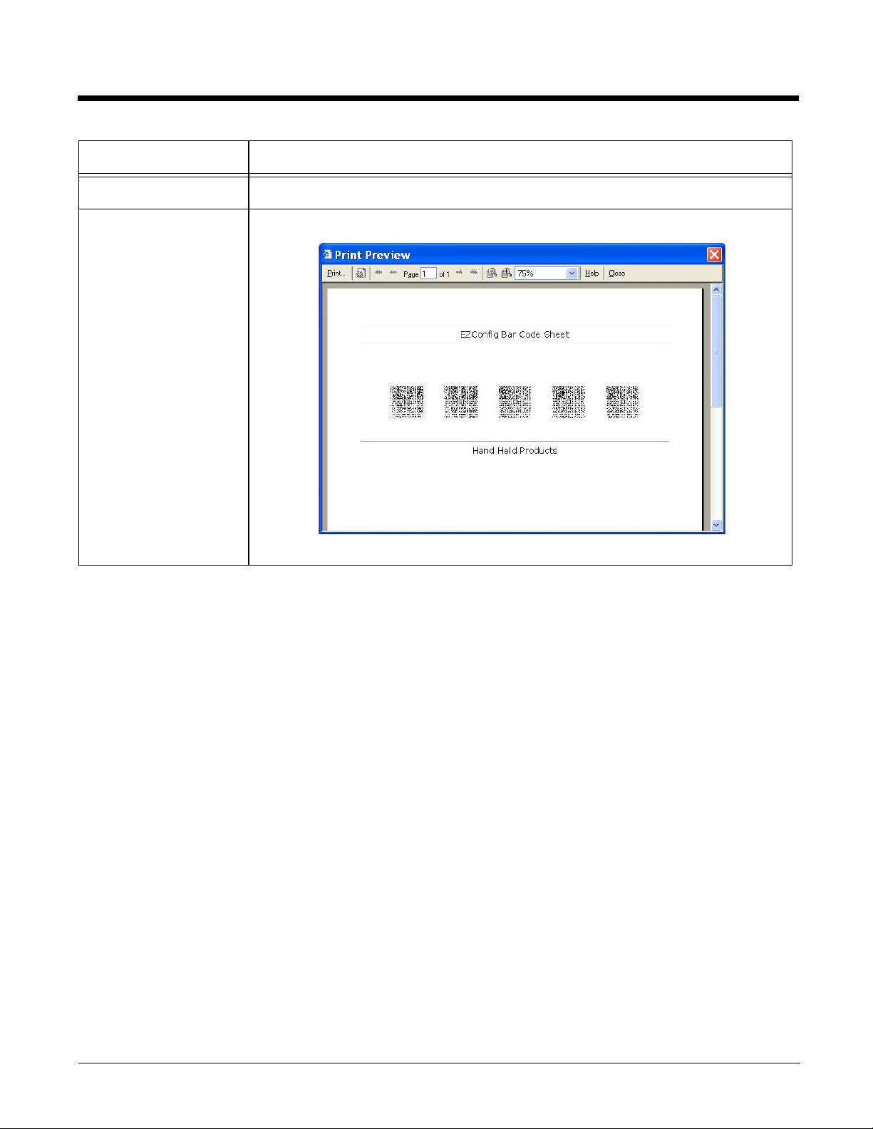
Field/Option Description
Save Saves the bar code sheet as an HTML file.
Preview Click to see a print preview.
Print on this window to print your bar codes.
Click
2 - 24
Page 41
Converting Known INI and MNU Files
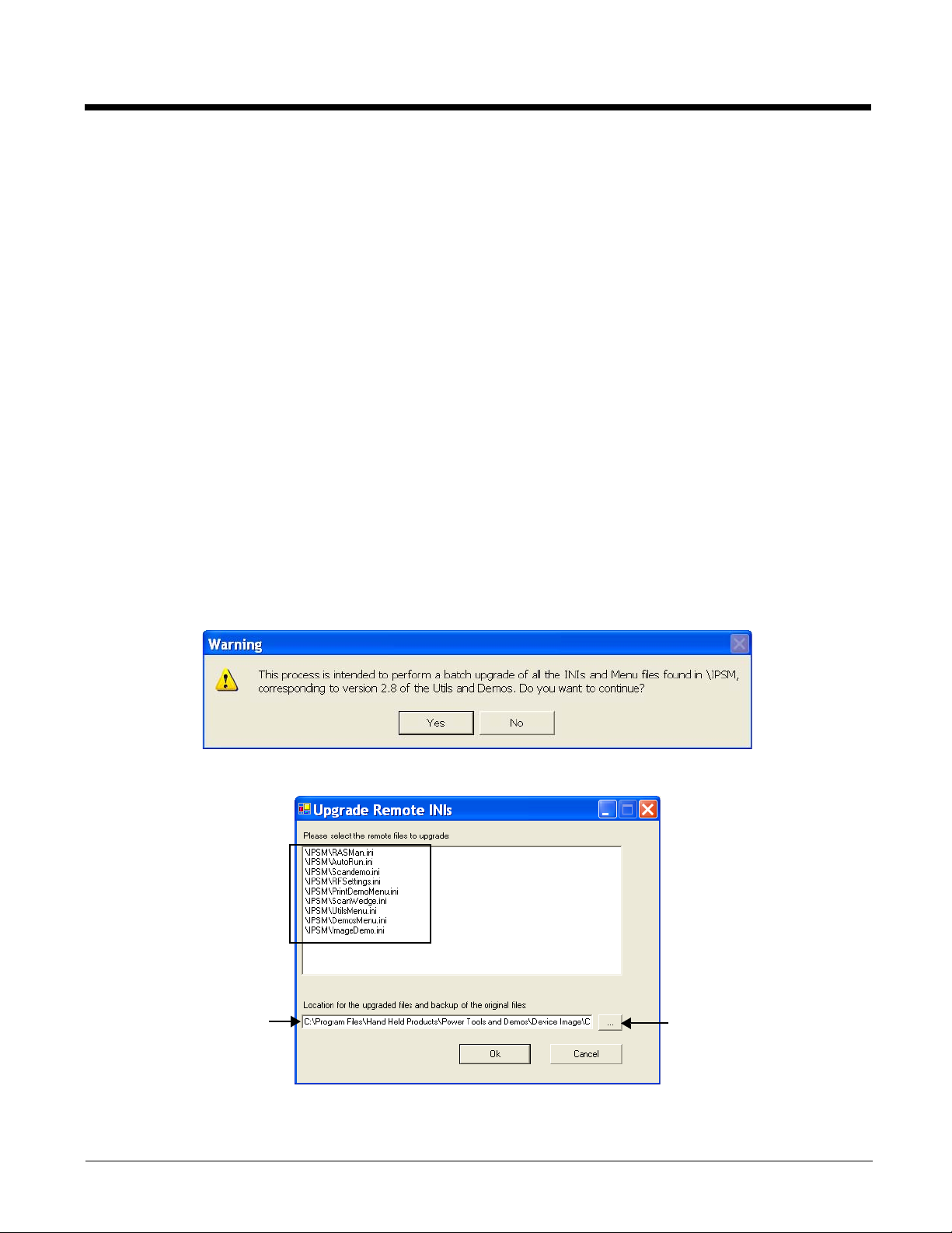
These are the INI
files found. Select
the files you would
like to convert.
SHIFT + click to
select more than
one file to convert.
This is the location
on the workstation
where the original
and converted file
will be stored.
Click this Browse
button to select
another location.
EZConfig Editor contains a batch conversion tool that converts known INI files on the terminal to the new
EXM file format.
EZConfig Editor pulls INI files from the
\IPSM folder of a remote device, converts them to the EXM file
format, and saves both original INI files and the converted EXM files in folders created on the workstation.
You don’t lose your original INI files in the conversion.
Note: You must have an ActiveSync connection between the workstation and the device to use this tool.
Known INI and MNU Files
•*Autorun.ini
•RASMan.ini
• Scanwedge.ini
• RFSettings.ini
• ImageDemo.ini
• ScanDemo.ini
• *Any EZMenu file (*.ini or *.mnu)
*These files must be converted using this tool to run properly on Dolphin terminals.
Converting Files
1. In EZConfig Editor on the workstation, click Tools > Upgrade Remote INI Files. You receive a
warning message describing what is about to happen.
2. Click Yes and EZConfig Editor retrieves remote INI files on the terminal and displays them in a list.
3. Select the files and the location on the workstation for the files. The default location on the
workstation is:
2 - 25
Page 42

C:\Program Files\Honeywell\Dolphin Power Tools and Demos\Device Image\Converted Files\Upgrade
X.
The X increases by one each time you run a batch conversion.
4. When you click OK, the conversion runs.
5. EZConfig Editor creates two folders inside the Upgrade X folder: Converted EXMs and Original
INIs.
Note: An Upgrade X folder with these two subfolders is created every time you run a conversion. Upgrades do not
save over each other.
6. Check each converted EXM file in EZConfig Editor.
Note: Even though conversion is complete, you have not yet upgraded your terminal! The old INI files remain in their
original location on the terminal.
Upgrading Dolphin Terminals
Once you approve of the converted EXM files, you must transfer them to the Dolphin terminals manually.
1. Delete the old INI files stored in the terminal.
2. Follow the steps for installing an upgrade on a Dolphin terminal (see Installing an Upgrade on the
Terminal on page 1-9) but don’t cold boot yet.
Note: You want to install an upgrade to make sure that you have the latest versions of AutoInstall.exe, Autorun.exe,
and EZConfig Editor on the terminal.
3. Transfer the new converted EXM files to the terminal and say yes when you are asked to replace the
existing files.
4. Cold boot the terminal. The new, converted EXM files install during AutoInstall.
2 - 26
Page 43
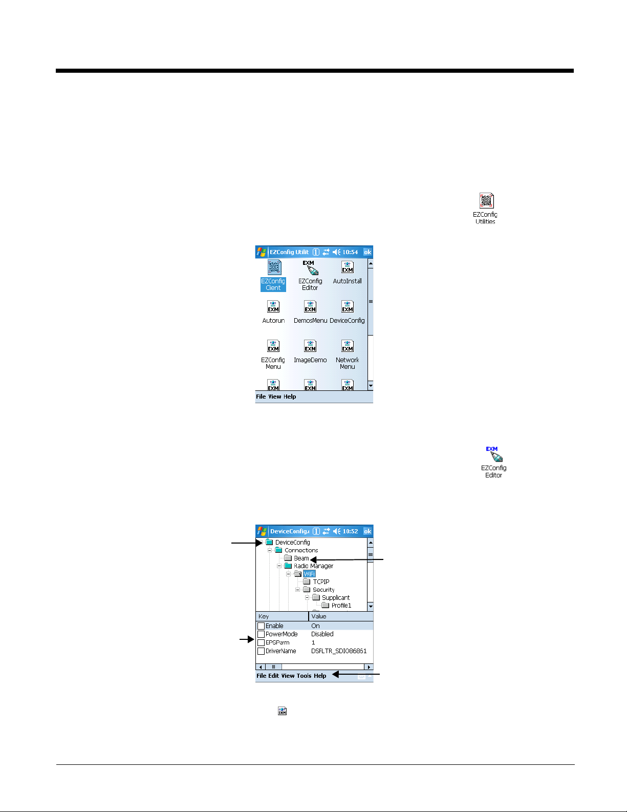
EZConfig Editor on the Terminal
The menus contain the same options as the
menus in EZConfig Editor on the
Sections appear in the top half of
the window.
Keys appear in the bottom half of
the window.
Enabled keys have a checkmark.
Disabled keys have a blank box.
Disabled sections appear in gray.
EZConfig Editor on the terminal edits and creates EXM files in the terminal and contains the same basic
functionality as the editor on the workstation.
Accessing EZConfig Editor
On Windows Mobile-based devices, tap Start > Power Tools > EZConfig Utilities .
On the Dolphin 7600, tap Start > Programs > Power Tools > EZConfig Utilities.
The EZConfig Utilities window provides access to both the EZConfig Editor and the EZConfig Client (see
EZConfig Client on page 2-31) as well as the EXM files on the terminal.
• To open EZConfig Editor without opening an EXM file, tap the EZConfig Editor icon . (You would
then tap File > Open to open an EXM file.)
• Tap directly on an EXM file to open it in EZConfig Editor.
The EZConfig Editor window opens displaying the contents of the selected EXM file.
Note: You can also use File Explorer to navigate to an EXM file and tap once on the file to open it in EZConfig Editor.
On the terminal, EXM files appear with an icon.
2 - 27
Page 44
Available Menus
The menus in the Command bar contain the same items as the menus in the EZConfig Editor on the
workstation.
File Menu
Edit Menu For details about each menu item, see Edit Menu on page 2-4. The Edit menu pops up
View Menu This menu enables you to view the locked icon over locked section folders.
Tools Menu For details about each menu item, see Tools Menu on page 2-5.
For details about each menu item, see File Menu on page 2-3.
Note: You cannot generate bar codes from EXM files on the terminal.
when you tap and hold on a section or key.
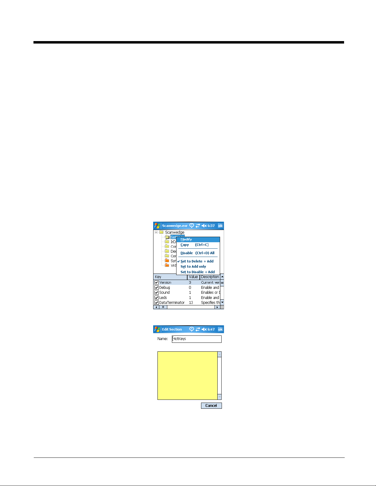
Editing Sections
Modifying the Section Name
To edit a section name or description, you have three options:
1. Select the section and tap Edit > Modify,
Select the section and press the ENTER key, OR
Tap and hold on the section name, then select Modify on the Edit menu that pops up.
2. All three options open the Edit Section window.
3. Tap inside the Name or Description fields and edit the text.
4. Tap OK to save changes. (You can also press the ENTER key.)
5. Tap Cancel to close the window without changes.
2 - 28
Page 45
Moving Sections
You cannot drag and drop to move sections in the tree. Use the Cut, Copy, Paste, and Paste as Child
items on the Edit menu to move sections.
Note: The Paste function pastes sections at the same level they were cut by default.
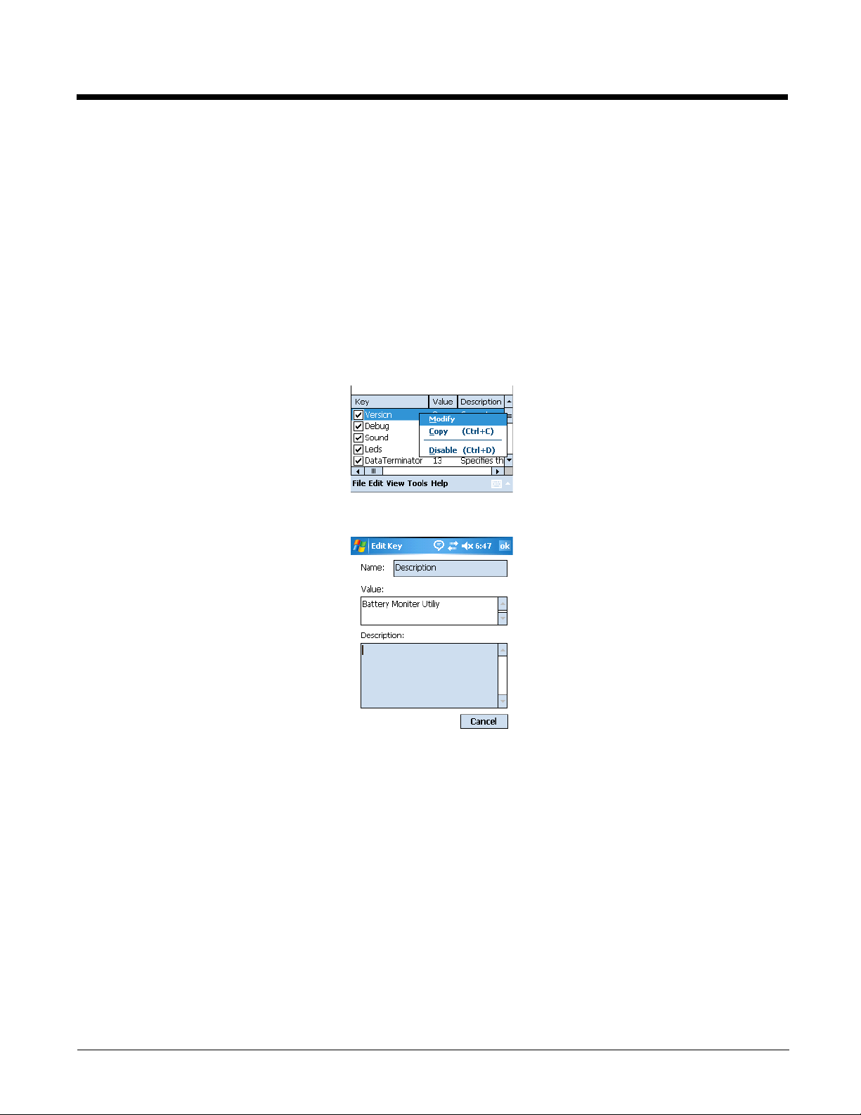
Editing Keys
Modifying Key Names and Descriptions
To edit a key’s name, value, or description, you have three options:
1. Select the key and tap Edit > Modify,
Select the key and press the ENTER key, OR
Tap and hold on the key’s name, then select Modify on the Edit menu that pops up.
2. All three edit options open the Edit Key window.
3. Tap inside the Name, Value or Description fields and edit the text.
4. Tap OK to save changes. (You can also press the ENTER key.)
5. Tap Cancel to close the window without changes.
Moving Keys
You cannot drag and drop to move keys. Use the Cut, Copy, and Paste as Child items on the Edit menu
to move keys.
2 - 29
Page 46
Launching Associated Applications
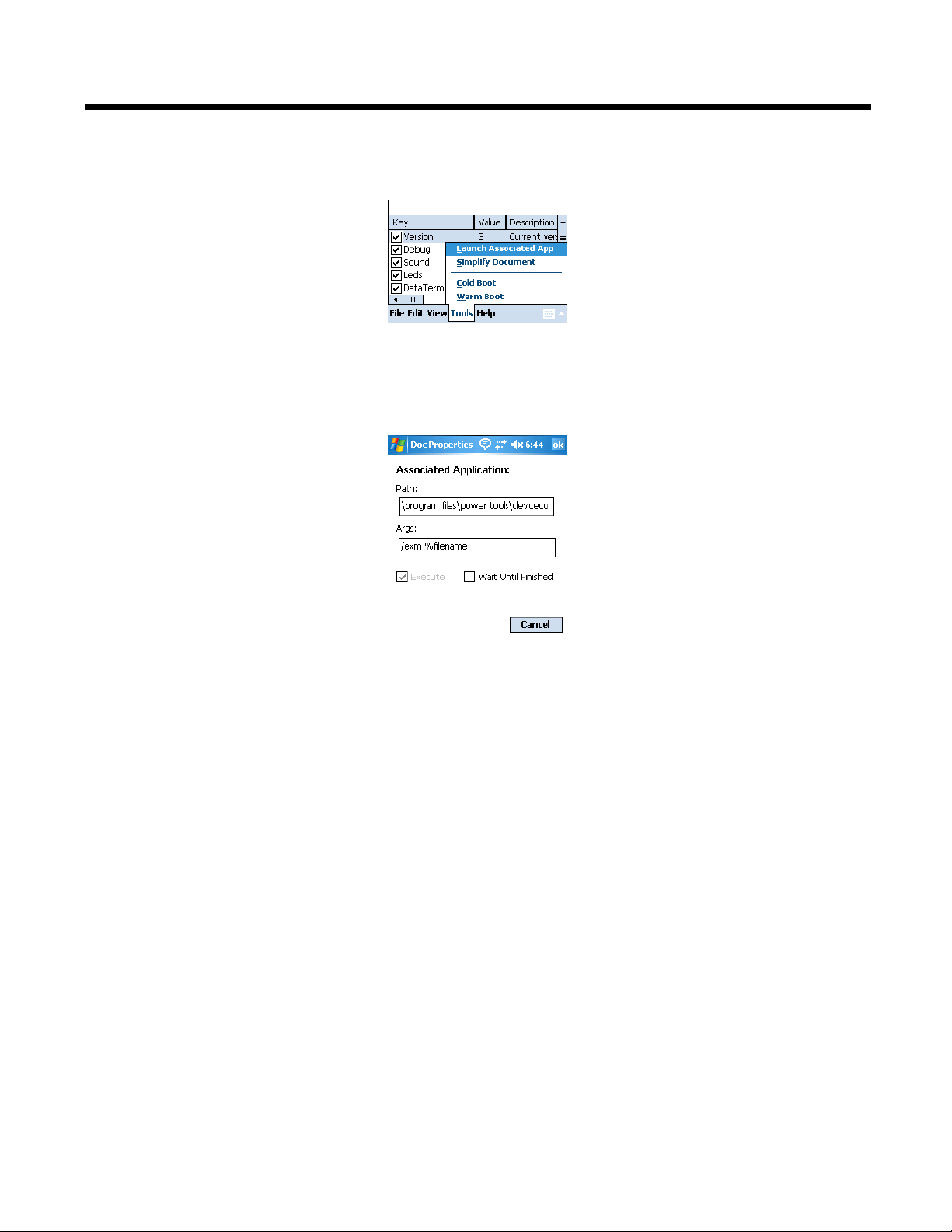
The Tools menu contains an item named Launch Associated App.
Launch Associated App is enabled only when there is an application associated with the EXM file.
Selecting this item automatically saves the open EXM file and launches the associated application while
the EXM file remains open.
To see the associated application, tap File > Properties.
The Path field contains the launch location of the application.
The Args field contains any command line arguments to execute when the application launches.
For more information about associating applications, see Associating Applications on page 2-15.
Example 1 - You’ve saved changes to an open DeviceConfig.exm file.
To apply those changes immediately, tap Tools > Launch Associated App. Because the
DeviceConfig.exm file is associated with DeviceConfig.exe by default, DeviceConfig launches and
applies the settings in the DeviceConfig.exm file.
Example 2 - You’ve saved changes to an open registry document.
Because registry documents are always associated with EZConfig Client, tapping Tools > Launch
Associated App updates the registry. EZConfig Client always updates the registry when launched from
an EXM file that is a registry document.
Example 3 - You’ve saved changes to an open ScanWedge.exm file.
And that ScanWedge.exm file has the following parameters as the associated application:
Path: \program files\power tools\scanwedge.exe
Args: /restart
Tapping Tools > Launch Associated App refreshes ScanWedge with the new settings.
2 - 30
Page 47
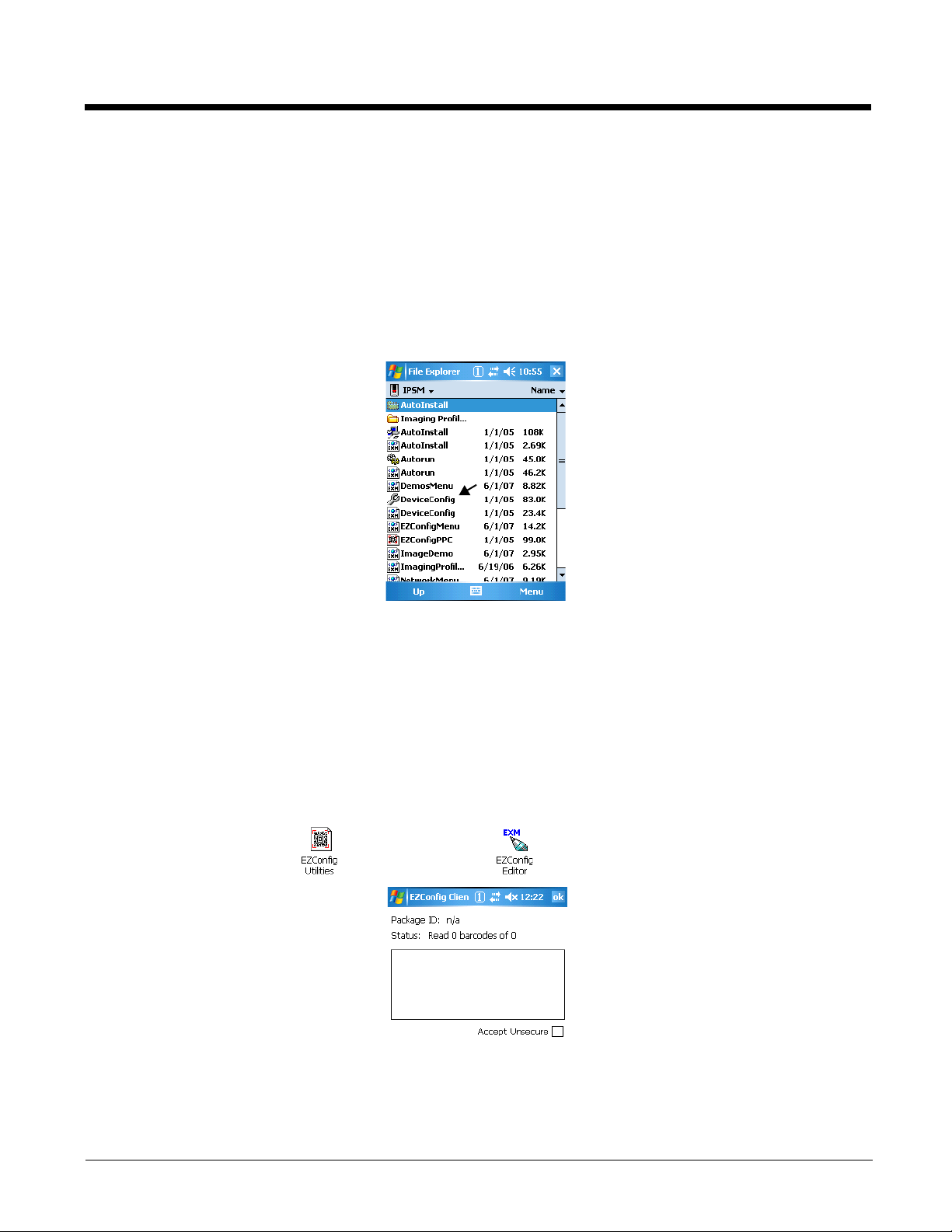
EZConfig Client
EZConfig Client decodes bar codes created in EZConfig Editor and deploys the data in the terminal. In
addition, if the EXM file in the bar code is associated with an application, EZConfig Client launches that
application, which then processes the decoded data.
EZConfig Client decodes bar codes with 40-bit and 128-bit encryption.
Storage Location
The EZConfig Client executable is stored in the \IPSM (\Honeywell for 6100/6500) folder.
For upgrades, EZConfig Client is located in the IPSM
workstation. This EXE must be copied and pasted into the \IPSM
the terminal. For more information, see Installing an Upgrade on the Terminal on page 1-9.
(\Honeywell for 6100/6500) image installed on the
(\Honeywell for 6100/6500) folder on
Using EZConfig Client
1. On the Dolphin terminal, tap Start > Power Tools. The Dolphin Power Tools Main Window (see
page 1-2) opens.
You can scan the first bar code from the Power Tools main window by pressing the SCAN key; see
page 2-34 for details.
EZConfig Client can also be launched with a HotKey from any window; see page 2-34 for details.
2. Tap EZConfig Utilities > EZConfig Editor . The EZConfig Client window opens.
3. Point the terminal at the first EZConfig Editor bar code, then press the SCAN key.
4. EZConfig Client decodes the bar code.
2 - 31
Page 48
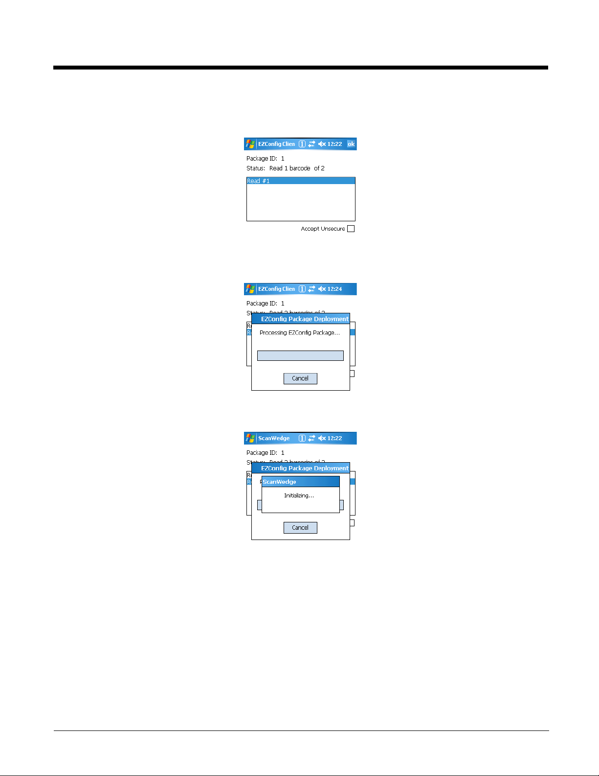
If there is only one bar code in the package, EZConfig Client deploys the package.
If there is more than one bar code in the package, EZConfig Client decodes the bar code, records that one bar
code has been read, and waits for the next scan.
5. Scan all the bar codes in the package. Bar codes can be scanned in any order.
6. When all bar codes in the package have been scanned, the EZConfig client deploys the data.
Note: If the EXM file is programmed to launch an application such as ScanWedge, a window pops up informing you
of initialization.
2 - 32
Page 49
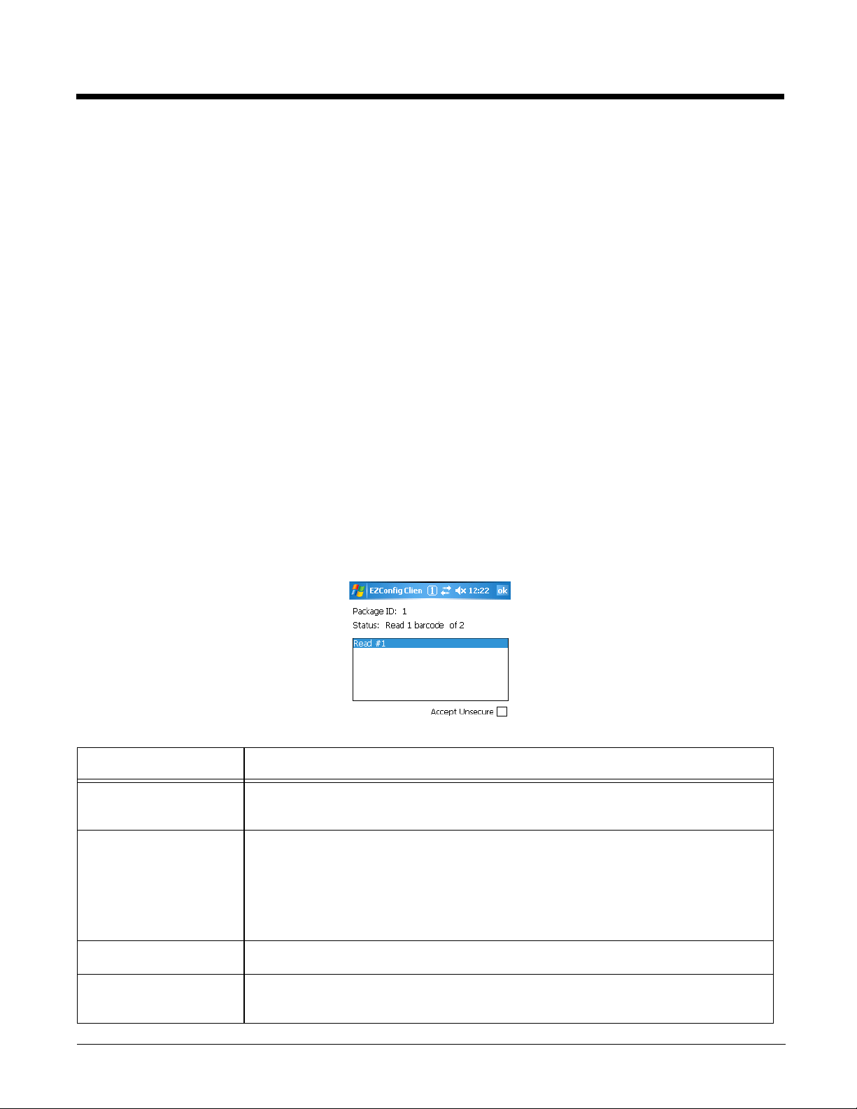
EXM File Processing
After decoding, EZConfig Client saves EXM files to the location in the terminal selected in the Remote
Path (page 2-20) field on the Bar Codes Tab (page 2-20). (If the Temporary, page 2-22, option is selected
in the bar code, EZConfig Client does not save the EXM file.)
There are two types of EXM files: configuration documents and registry documents. EZConfig Client
processes each type of file differently.
Configuration Documents
If the EXM file was associated with an application, EZConfig Client launches and deploys
the data to that application for processing.
Note: DeviceConfig.exm
the terminal appropriately. After decoding the bar code, EZConfig Client deploys the
data to DeviceConfig.exe, which applies the settings to the terminal.
must
be associated with DeviceConfig.exe to be processed on
Registry DocumentsRegistry documents are always associated with EZConfig Client. The Execute option
(Execute, page 2-15) determines whether the registry is updated or not. If Execute is
selected, EZConfig Client updates the registry immediately after decoding the bar code.
Multiple Bar Codes
Some EXM files generate more than one bar code. If multiple bar codes were generated, EZConfig Client
recognizes that there is more than one bar code in the package and tracks each bar code scanned and
decoded. Bar codes can be scanned in any order, but EZConfig Client does not deploy the data until all
the bar codes in the package have been scanned.
EZConfig Client Window
Field Description
Package ID This is the ID of the entire package.
EZConfig Editor assigns an ID to bar code packages when creating the bar code.
Status This field displays the decode status of the bar codes scanned so far.
If there is more than one bar code in the package, this field acts as a decode
counter.
The Status field displays:
• How many bar codes have been scanned and
• How many bar codes are in the package
Read # box This box displays the list of bar codes scanned and decoded.
Accept Unsecure This option allows EZConfig Client to scan bar codes that are not encrypted.
Note: By default, all bar codes created in EZConfig Editor are encrypted.
2 - 33
Page 50

Scanning Bar Codes Directly from the Power Tools Main Window
When the Power Tools or Demos main windows are open, press the SCAN key and:
• If there is only one bar code in the package, EZConfig Client decodes and deploys the bar code without
opening the EZConfig Client window.
• If there are multiple bar codes in the package, EZConfig Client decodes the first bar code and opens
the EZConfig Client window showing that one bar code in the package has been scanned.
Launching EZConfig Client with a HotKey
Pressing ALT + SCAN launches EZConfig Client from any application window after you activate the
HotKeys Power Tool; see HotKeys on page 6-5.
ScanWedge
Bar code decoding in EZConfig Client is compatible with ScanWedge. You can set ScanWedge to pass
bar code information to EZConfig Client for further processing. For details, see Accept EZConfig on page
5-4.
Command Line Arguments
/%filename Executes the EXM file; this is the default entry.
/q Quiet mode
/s Full screen
/o No menu
/e Exit if first scan fails to deliver a valid bar code
/u Accept (decode) unsecure bar codes
2 - 34
Page 51

3
DeviceConfig
Overview
DeviceConfig consists of the DeviceConfig.exe and the DeviceConfig.exm file located in the \IPSM
(\Honeywell for 6100/6500) folder. DeviceConfig.exe looks for and applies the settings in the
DeviceConfig.exm file.
Note: On the Dolphin 7600, the DeviceConfig.exe is located in the \Program Files\Power Tools folder.
DeviceConfig.exm File
The DeviceConfig.exm file contains terminal configuration settings. Because this file is stored in the
\IPSM
be considered system defaults.
Enabling DeviceConfig Functionality
By default, all sections except the About Section (see page 3-12) are disabled, which means that the key
values are not applied to the terminal. To use the DeviceConfig.exm file to configure the terminal, enable
the sections and keys required by your configuration in EZConfig Editor (page 2-2) on the workstation or
EZConfig Editor on the Terminal (page 2-27).
(\Honeywell for 6100/6500) folder, its configuration settings persist through cold boots and should
Autorun
Autorun (see page 4-1) launches DeviceConfig.exe, which applies the DeviceConfig.exm settings, then
launches a cold boot followed by a warm boot.
Bar Code Delivery
When the DeviceConfig.exm file is delivered to the terminal via bar code, EZConfig Client launches
DeviceConfig.exe automatically after decoding. DeviceConfig.exe then applies the settings in
theDeviceConfig.exm file in the terminal. For more information, see Creating Bar Codes (page 2-19) and
EZConfig Client (page 2-31).
The DeviceConfig.exm file must be associated with DeviceConfig.exe for EZConfig Client to launch
DeviceConfig.exe after decoding the bar code. In EZConfig Editor, the associated application path must
be
\IPSM\deviceconfig.exe
For more information, see Associating Applications, page 2-15.
(\Honeywell for 6100/6500)
Settings in Control Panel Applets
Many settings in the DeviceConfig.exm file have matching Control Panel applets on the terminal that allow
the user to enter and save the same values. If a user changes a setting in the Control Panel applet on the
terminal, that setting is applied but stored in RAM memory and erased during the next cold boot. During
the next cold boot, Autorun launches DeviceConfig, which then re-applies the settings in the
DeviceConfig.exm file.
WLAN Settings
When enabled, the WiFi section of the DeviceConfig.exm file creates profiles that will
appear in the WLAN control panel applets. Those profiles will have the same names as the
value entered in the SSID (see page 3-4) key.
3 - 1
Page 52

DeviceConfig.exm Sections and Keys
The sections and keys in the DeviceConfig.exm file are locked, which means that you can change values
but not names or descriptions.
Section Name Description See
Page
Connections Configures communication parameters. There are child sections that
configure the IrDA port, the on-board radios, and the ActiveSync
connection.
System Configures basic system settings. 3-12
Applications Configures software applications. 3-15
3-2
Connections Section
The Connections section contains child sections that set communication parameters on the terminal.
Beam Section
The Beam section enables and disables the IrDA port.
Radio Manager Section
Note: Only the Enable key is supported on the Dolphin 6100/6500/7600. You can use DeviceConfig to enable and
disable the radio but not to configure it.
In the Radio Manager, typically, you would enable the radio in the WiFi section, enable DHCP in the
TCPIP section, then configure the radio settings in the Security\Supplicant\ProfileX or
Security\NonSupplicant section.
WiFi Section–Dolphins 7850, 7900, and 9500
The keys in the WiFi section control the settings of the WLAN radio.
Key Description Defaul
t Value
Enable Enables and disables the WLAN radio. 1
PowerMode Specifies the power save mode. 1
EPSParm When PowerMode is set to 3 (Auto
Enable), this parameter specifies radio
vs. battery performance.
3 - 2
N/A
Available Values
0=Disabled
1=Enabled; if enabled, the GSM radio
section is disabled automatically
1=Disable; radio is powered constantly
(power save mode is not used)
2=Always Enable; power save mode is
used
3=Auto Enable; EPSParm key defines
radio vs. battery performance
X=A value between 1 and 10, where:
1=Best Radio Performance (Minimum)
10=Best Battery Life (Maximum)
Page 53

WiFi Section–Dolphins 7850, 7900, and 9500
The keys in the WiFi section control the settings of the WLAN radio.
Key Description Defaul
Available Values
t Value
DriverName Specifies the name of the radio driver.
This string must match the name of the
driver for the current device.
N/A
X=A value in the drop-down list; radio
driver names are terminal-specific.
Different Dolphins have different radio
drivers.
TCPIP Section
The keys in the TCPIP section determine how the radio handles IP addresses.
Key Description Defaul
t Value
DHCP Enables and disables DHCP (Dynamic
1
Host Configuration Protocol).
The remaining keys need to be set when DHCP is disabled. When DHCP is enabled, these numbers are
dynamically requested from a DHCP server.
IPAddress Static IP address for the radio interface. N/A Static IP address
Available Values
0=Disabled; the static IP address in the
IPAddress key is used for the radio
interface.
1=Enabled; the IP address for the radio
interface is requested from a DHCP
server.
SubnetMask SubNet mask for the static IP address. N/A Subnet mask address
DefaultGateway
DNS Domain name server for the static IP
Default gateway for the static IP address. N/A Gateway address
N/A Domain name server address
address.
Domain Domain name for the terminal N/A Terminal’s domain name
WINS Windows name server. N/A Windows name server address
3 - 3
Page 54
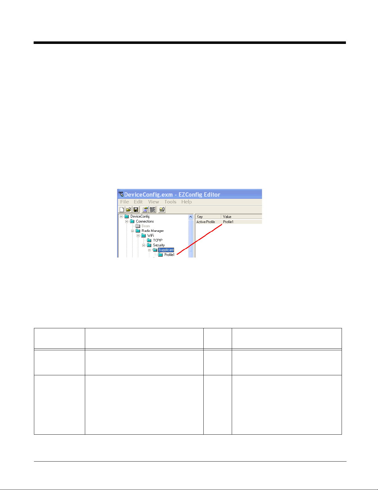
Security Section
The Security section has no keys but two child sections: Supplicant and Non Supplicant.
Supplicant Use this section to configure the WLAN radio on Dolphin 7850 terminals; see Supplicant
Section–Dolphin 7850 on page 3-4.
NonSupplicant Use this section to configure the WLAN radio on Dolphin 7900 and 9500 terminals; see
NonSupplicant Section–Dolphins 7900 and 9500 on page 3-6.
Supplicant Section–Dolphin 7850
The Supplicant section consists of a number of child sections. The default child section is named Profile1
and contains all the keys necessary to create a configuration profile for the WLAN radio.
To create multiple radio configurations, copy the Profile1 section and paste it at the root level of the
Supplicant section. Then, rename that profile and configure the keys according the desired network
configuration. Each child section name is arbitrary, but each name must be different.
The Supplicant section contains one key named ActiveProfile. Type in the Value equal to name of one
of the desired profile child sections.
When DeviceConfig is activated on the terminal, the terminal will apply the settings in the profile specified
in the ActiveProfile key. If the ActiveProfile key does not have a matching profile, the radio will be enabled
by DeviceConfig but no specific radio configuration will be activated, which means that the radio will not
connect to your network.
Profile Subsections–Dolphin 7850
Each Profile subsection contains the keys that configure the radio connection from the terminal to the
network.
Key Description
SSID The service set identifier used to
connect to network; usually the network
name of the access point or peer station.
Assoc. Mode The general association mode
(sometimes called “authentication”) of
the radio.
Default
Val ue
N/A
N/A
Available Values
X=Your network’s SSID
Any=Connect to any network
• None (no authentication or
encryption)
•WEP
• IEEE 802.1X
• WPA-Personal (PSK)
• WPA-Enterprise (EAP)
• WPA(2)-Personal (PSK)
• WPA(2)-Enterprise (EAP)
3 - 4
Page 55

Profile Subsections–Dolphin 7850
Each Profile subsection contains the keys that configure the radio connection from the terminal to the
network.
Key Description
Encryption The encryption mode available for the
association mode.
EAP Method Available EAP methods for IEEE 802.1X
and WPA(2)-Enterprise (EAP)
association modes.
PSK Enter the private share key for the WEP
association mode.
Identity This is the 802.1X identity supplied to
the authenticator. The identity value can
be up to 63 ASCII characters and is
case-sensitive.
Default
Val ue
N/A
N/A
N/A User-defined
N/A User-defined
Available Values
• Open & Shared (WEP)
• TKIP, AES-CCMP, TKIP & CCMP
(WPA)
•LEAP
• PEAPv0-MSCHAPV2
• PEAPv1-MSCHAPV2
• PEAPv1-GTC
• PEAPv1-TLS
• FAST-MSCHAPV2
•FAST-GTC
• FAST-TLS
•TLS
• TTLS-MD5
• TTLS-MSCHAPV2
•TTLS-GTC
Password This is the password used for MD5-
Anonymous ID Enter the anonymous ID. This ID creates
Tunne l PAC
Machine PAC
Provisioning Provisioning refers to service activation
Challenge or EAP authentication. It may
contain up to 63 ASCII characters and is
case-sensitive. Asterisks appear instead
of characters for enhanced security.
a tunnel through which the real ID (as
entered in the Identity field) can pass.
For additional security, make this ID
different than the one entered in the
Identity field.
For EAP-FAST, a one-time provisioning
exchange establishes a shared secret,
called a Protected Access Credential
(PAC) Key. That PAC Key is used for all
subsequent authentications.
and involves programming various
network databases with the customer's
information.
N/A User-defined
N/A User-defined
N/A Enter the address on the Dolphin
terminal of either PAC (tunnel or
machine).
The PACs must be located on the
Dolphin terminal!
N/A
• No Provisioning
• Anonymous
• Authenticated
• Anonymous + Authenticated
3 - 5
Page 56

Profile Subsections–Dolphin 7850
Each Profile subsection contains the keys that configure the radio connection from the terminal to the
network.
Key Description
CA and/or
Client
Certificate
Private Key Private keys are used with certain types
Priv Key
Password
WEP Key
Mode
• CA certificates are any certificates
created by a certified authority (CA).
• Client certificates contain information
that identifies the user, as well as
information about the organization that
issued the certificate. This ensures
that you can encrypt data end-to-end.
of EAP authentication.
Private keys can be locked by
passwords.
Mode being used by the WEP keys (in
Key1–Key4 keys).
Note: Key validation occurs when
DeviceConfig is loaded on the
terminal (often during Autoinstall),
not when you save the
DeviceConfig.exm file.
Default
Val ue
N/A
N/A
N/A
N/A
Available Values
Enter the address on the Dolphin
terminal of either certificate (CA or
Client).
The certificates must be located on
the Dolphin terminal!
Enter the address on the Dolphin
terminal of the private key.
The private key must be located on
the Dolphin terminal!
Enter the password that unlocks the
private key.
ASCII uses all alpha numeric
characters. HEX uses only numerics
and A-F.
Valid lengths are as follows:
• 64-bit ASCII=5
• 128-bit ASCII=13
• 64-bit HEX=10
• 128-bit HEX=26
WEP Key1–
Key4
Active Key Enter the number of the key that you
In fields Key 1—Key 4, enter the specific
key. The format of each key must match
the key length type selected in the WEP
Key Mode key.
To use dynamic keys in your
configuration, leave all the key fields
blank.
want to be active in this configuration.
N/A User-defined
N/A 1, 2, 3, or 4
NonSupplicant Section–Dolphins 7900 and 9500
Key Description Defaul
t Value
SSID The service set identifier used to
connect to network; usually the network
name of the access point or peer station.
3 - 6
N/A
Available Values
X=Your network’s SSID
Any=Connect to any network
Page 57

NonSupplicant Section–Dolphins 7900 and 9500
Key Description Defaul
t Value
NetworkType Determines the type of network the radio
1
should access.
TxRate Defines the transmit rate. 15
Channel Channel (1-11) of the RF adapter.
10
In general, this parameter is used only in
AdHoc network mode.
APSearchThre
shold
Specifies how easily the radio switches
from the current access point to a new
Low
Density
one in a roaming network. Selecting
Low, Medium, or High depends on how
close the coverage areas or the access
points are in your installation.
Available Values
0=AdHoc (Minimum)
1=Infrastructure
2=Pseudo-AdHoc
1=1 Mb (Minimum)
2=2 Mb
3=Auto 1/2 Mb
4=5.5 Mb
8=11 Mb
15=Fully Auto (Maximum)
1=Minimum
11=Maximum
Low Density=Select if your installation
consists of access points with little
overlap in their coverage areas to make
the radio switch faster before its signal
becomes too low.
Medium Density=Select if your installation
consists of access points with medium
overlap in their coverage areas.
High Density=Select if your installation
consists of access points with high
overlap in their coverage areas to
prevent the radio from switching too
often.
Encryption Specifies the encryption method. 0
Authentication Specifies the authentication mode. 0
Active Key Specifies the key to use to encrypt
transmitted data.
Note: These keys are used only if 1 or 2
is selected as the Encryption
method.
Key1–4 Defines keys 1–4.
Note: The keys in this section are
encrypted; see Encrypted on page
2-13. EZConfig Editor and
EZConfig Client both support
encryption
.
0
None
0=No Encryption
1=WEP 64-bit RC4 encryption
2=WEP 128-bit RC4 encryption
0=Open; WEP keys are not used
1=Shared; WEP keys are used
2=Automatic; auto-discriminates between
Open and Shared authentication
modes
1=Key1 key
2=Key2 key
3=Key3 key
4=Key4 key
ASCII–Use quotes for the value; e.g.,
"hello")
Hex–Type the pair of hex values in a row;
e.g., AFB0FF415A
64-bit encryption–Length must be 5
characters or 5 hex pairs
128-bit encryption–Length must be 13
characters or 13 hex pairs
3 - 7
Page 58

Bluetooth Section
Bluetooth Section—Dolphin 6100/6500/7600
The keys in this section enable the Bluetooth radio and configure Bluetooth printer settings.
Key Description Default
Available Values
Value
Enable Enable and disable the Bluetooth radio.
This is the top level of the tree; printer
1
0=Disable
1=Enable;
settings are in a child section.
Default Printer This section configures a default Bluetooth printer by setting it up as a virtual COM Port.
Address
Channel
COMPort
Bluetooth MAC Address of the printer. N/A MAC Address
Printer's RFCOMM protocol channel (1–31). 0
Number to assign to the virtual COM Port. 0
X=1–31
0=Autodiscovery (recommended)
X=The specific COM port
0=Autofind (recommended); the
terminal detects the next available
port and selects it for the BT
printer.
Bluetooth Section—Dolphins 7850, 7900 and 9500
The keys in this section enable the Bluetooth radio and configure a Bluetooth printer as a Favorite.
If there is no Bluetooth radio installed in the terminal, disable this section.
Key Description Default
Value
Available Values
Enable Enable and disable the Bluetooth radio.
This is the top level of the tree; printer
settings are in a child section.
1
0=Disable
1=Enable; the GSM radio is disabled
automatically
Default Printer This is a child section that configures a Bluetooth printer as a Favorite Bluetooth Device. By
entering the necessary information from the Bluetooth printer in the DeviceConfig.exm file,
and then distributing that file to a group of terminals, you can bypass the manual process of
setting up a printer as a Bluetooth Favorite on each terminal.
Address
Bluetooth MAC Address of the printer;
N/A MAC Address
see Obtaining the MAC Address–
Dolphins 7900 and 9500 on page 3-9.
Service
Hex value of the printer serial service to
1101 Hex value
use.
DeviceName
Friendly name of the printer. N/A Printer name
3 - 8
Page 59
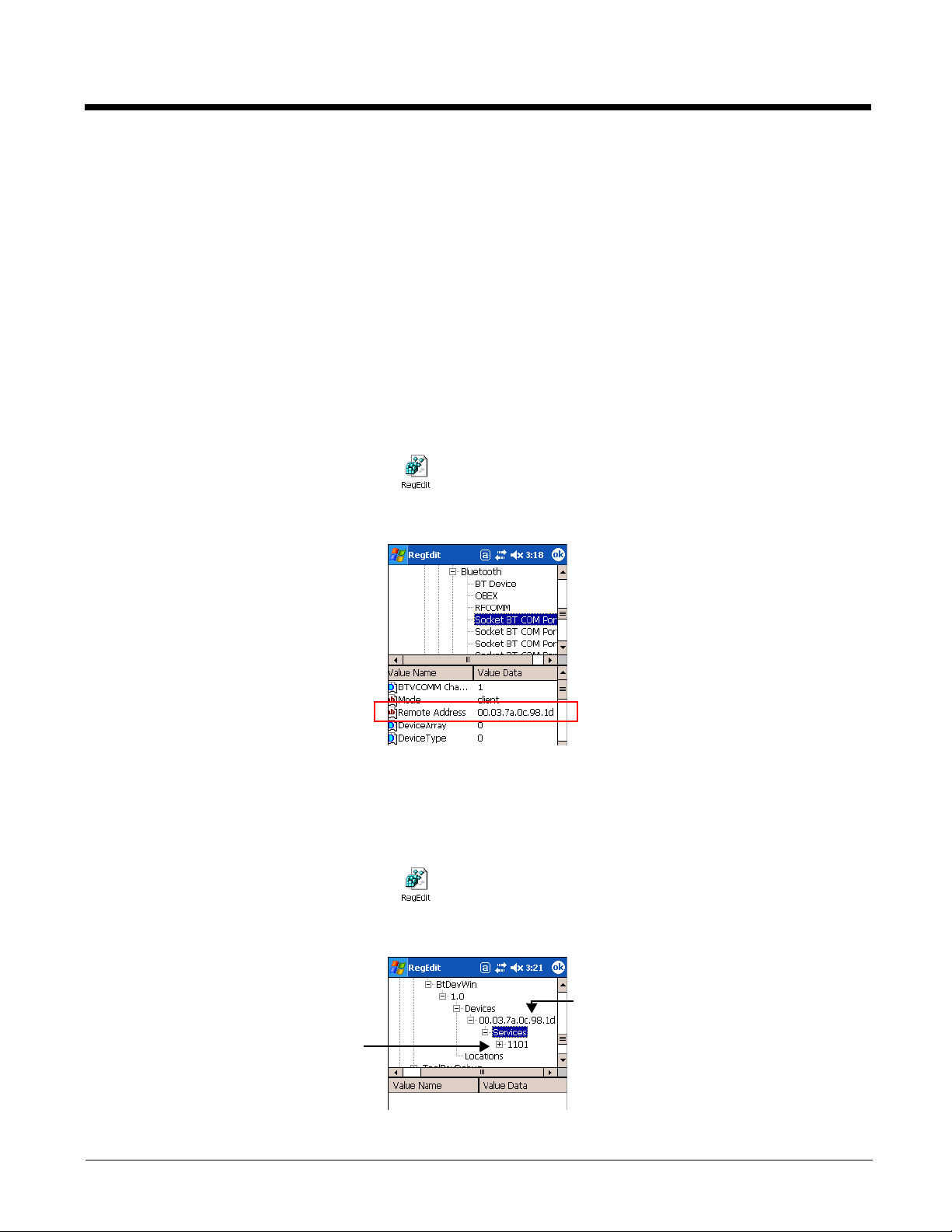
Bluetooth Default Printer Values–Dolphins 7900 and 9500
This is the MAC
Address of the
printer.
This is the hex
value of the
printer’s serial
service.
In general, to establish a printer as a Bluetooth Favorite Device, you must establish the printer as a
Bluetooth Favorite on the terminal. The problem is that Bluetooth Favorite settings are stored in RAM
memory and therefore erased during each cold boot. The Default Printer section stores these settings
permanently in the DeviceConfig.exm file so the printer remains a Favorite after a hard reset.
Furthermore, you can distribute a DeviceConfig.exm file with the printer settings to multiple terminals.
After DeviceConfig.exe applies the settings in the DeviceConfig.exm file (launched manually or after a
hard reset), the printer is set up as a Favorite automatically, without any special configuration to each
terminal.
After you have established a printer as a Bluetooth Favorite Device on an individual terminal, obtain the
values for the Address and Service keys from the registry in RegEdit.
Obtaining the MAC Address–Dolphins 7900 and 9500
After you have set up the Bluetooth printer on the terminal, use RegEdit to find the printer values.
1. Tap Start > Power Tools > RegEdit .
2. Navigate to HKEY_LOCAL_MACHINE > SOFTWARE > Socket Communications > Bluetooth >
Socket BT Com Port.
3. Copy the Value Data in the Remote Address field. This is the MAC address of the printer.
4. Enter this address in the Address key in the Bluetooth > DefaultPrinter section of the
Hex Value of the Printer’s Serial Service–Dolphins 7900 and 9500
1. Tap Start > Power Tools > RegEdit .
2. Navigate to HKEY_LOCAL_MACHINE > SOFTWARE > Socket Communications > BtDevWin >
DeviceConfig.exm file.
1.0 > Devices > [MAC Address] > Services.
3 - 9
Page 60

3. Copy the first number underneath Services. This is the hex value for the Service key field; “1101” in
the illustration above.
Note: For more detailed information about RegEdit, see RegEdit on page 8-1.
GSM Section—Dolphins 7900 and 9500
The GSM section configures the GSM/GPRS radio on the Dolphin 7900 and 9500. If there is no GSM
radio installed in the terminal, disable this section.
Key Description Default
Value
Enable Enables and disables the GSM radio. 0
APN Enter the Access Point Name (APN) for
Empty
the GPRS network.
IPAddress Enter the IP Address. Empty
Protocol Enter the protocol to use. IP
Username Enter the username for the GPRS
Variable
connection.
Password Enter the password associated with the
Variable
username for the GPRS connection.
Note: This key is encrypted; see
Encrypted on page 2-13.
Available Value
0=Disable
1=Enable; when enabled, the WLAN
radio turns off automatically.
APN value
Empty=GSM uses DHCP (server-
assigned IP address)
X=IP address
Protocol type
Empty=Disabled
0=Disabled
X=The username for the GPRS
connection.
Empty=Disabled
0=Disabled
X=The password for the GPRS
connection.
ActiveSync Section
The ActiveSync Section configures the terminal’s ActiveSync connection parameters.
Key Description Default
Value
AutoConnect Enables and disables the ActiveSync
1
connection when the terminal first
connects to the communication peripheral.
3 - 10
Available Values
0=Disable ActiveSync connection
1=Enable ActiveSync connection
Page 61

ActiveSync Section
The ActiveSync Section configures the terminal’s ActiveSync connection parameters.
Key Description Default
Value
Connection Specifies the connection type and baud
rate.
‘USB
Connect
ion
Available Values
Dolphins 7850, 7900, & 9500:
`USB Connection
`115200 Default
`19200 Default
`38400 Default
`57600 Default
Dolphin 6100/6500/7600:
`115200@Desktop
`Infrared Port (not applicable to
6100/6500)
`USB
`Bluetooth
Note: These values must be typed
in exactly as they appear
here.
3 - 11
Page 62
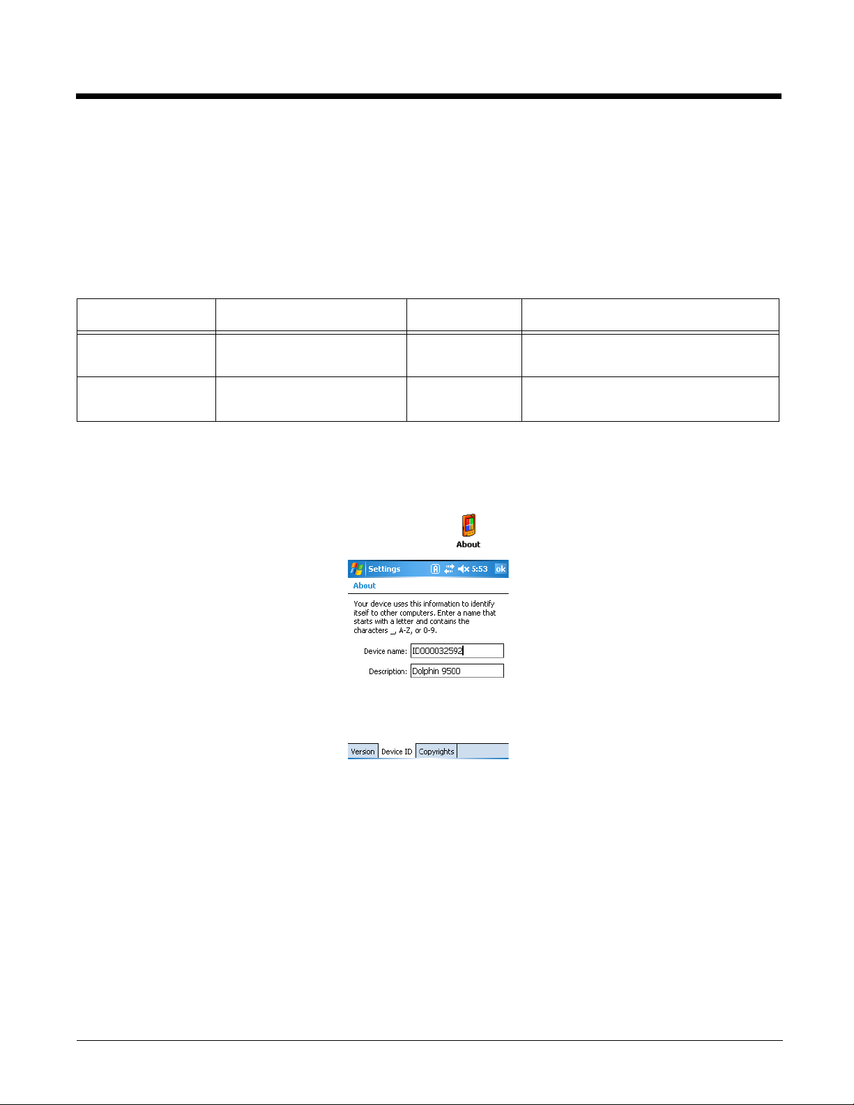
System Section
The System section contains child sections that configure various system settings. For specifics on each
sections and their keys, refer to the Description sections in the DeviceConfig.exm file itself.
About Section
The About section sets a unique device name and description for the terminal.
By default, this section is enabled and applied to the terminal after each cold boot.
Key Name Description Default Value Available Values
DeviceName Sets the name of the device. ID[SerialNumb
er]
DeviceDescription Sets the device description Dolphin 9500 User-defined; however, the description
See DeviceName Restrictions on page
3-12.
cannot exceed 15 characters in length.
Device ID Tab—Dolphins 7850, 7900, & 9500
The values of the DeviceName and DeviceDescription keys appear in the Device name and
Description fields on the Device ID tab on the terminal.
On the Dolphin terminal, tap Start > Settings > About > Device ID tab.
Note: ActiveSync recognizes the Device name and Description from this applet.
DeviceName Restrictions
• The DeviceName must begin with a letter.
• The DeviceName cannot exceed 15 characters in length.
• Any text outside brackets (“[xxxx]”) will appear as text in the Device name field.
Content What appears in the Device name field…
[SERIALNUMBER] The terminal’s serial number pulled dynamically from the kernel.
[MODELNUMBER] The terminal’s model number pulled dynamically from the kernel.
3 - 12
This is the serial number that appears in SysInfo (see page 6-16) as the Terminal Serial
Number (see page 6-18).
This is the serial number that appears in SysInfo (see page 6-16) as the Model Number
(see page 6-18).
Page 63
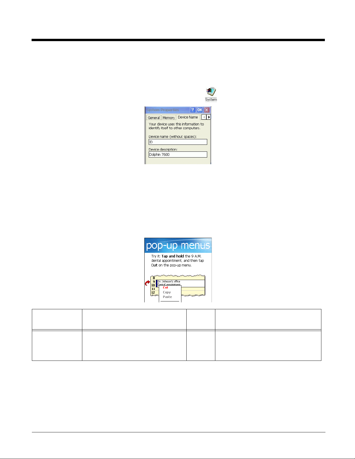
Device Name Tab—Dolphin 6100/6500/7600
The values of the DeviceName and DeviceDescription keys appear on the Device Name tab in the
System control panel applet.
Tap Start > Settings > Control Panel > double-tap System > Device Name tab.
Power Management Section
Note: The RS232 5V Power Out section is not supported on the Dolphin 7850 terminal.
Welcome Screen Section–Dolphins 7850, 7900, & 9500
The Welcome Screen section allows you to bypass the Windows Mobile startup screens after each cold
boot. These screens are the standard windows that walk you through using the stylus and pop-up menus;
for example:
Key Description Default
Value
Enable This is a special key that bypasses
the Windows Mobile startup screens
at startup.
0 0=Enable; the Pocket workstation screens
Available Values
do not appear after each hard reset.
1=Disable; the Pocket workstation screens
appear after each hard reset.
Launching DeviceConfig.exe
Because the settings in the User Interface section alter the AutoInstall process, DeviceConfig.exe must
be launched manually after the DeviceConfig.exm file is uploaded to the terminal. DeviceConfig.exe
processes the DeviceConfig.exm file and applies this setting before the next hard reset.
3 - 13
Page 64

If DeviceConfig.exe is not launched manually prior to the next hard reset, this setting is not applied and
the Welcome screens appear during the next startup. Then, when Autorun launches DeviceConfig.exe
next
during startup, this setting is applied and the Welcome screens are removed from the
hard reset.
See Launching DeviceConfig.exe Manually on page 3-17.
Autorun.ini
When the Welcome section is enabled and applied by DeviceConfig.exe, a small Autorun.ini file is created
in the \IPSM folder. This .ini file contains the Welcome screen information. Do not remove this created
file!
RAM Section
The RAM section allows you to provision RAM memory on Windows Mobile 5.0-based terminals.
Key Description Default
Val ue
Split This is the RAM split percentage;
the percentage that will be
allocated to the filesystem.
Prompt Determines whether the system
prompts you before the memory is
re-allocated.
50
1
Available Values
Min=0
Max=100
See Split Restrictions on page 3-14.
0=Disabled; you will not be prompted.
DeviceConfig’s settings are applied
automatically.
1=Enabled; you are prompted before the
memory is re-allocated.
Note: If the allocation is the same, nothing
will occur.
Split Restrictions
The percentage split you are able to enter is specific to each terminal’s memory configuration. Min/max
ranges can be retrieved from SysInfo or SetRAM.
•See RAM INFO on page 6-21.
•See SetRAM Window on page 11-2.
AutoInstall
When the RAM section is enabled on Windows Mobile 5.0-based devices, AutoInstall.exe launches
DeviceConfig in a mode that checks only the memory allocation in the RAM section of DeviceConfig.exm
against the terminal’s current memory allocation.
If there is a discrepancy and the Prompt key in the RAM section is enabled, a prompt appears asking if
you want to apply the memory allocation in DeviceConfig. If there is a discrepancy and the Prompt key in
the RAM section is disabled, the memory allocation in DeviceConfig is applied.
Note: AutoInstall.exe launches the RAM section of DeviceConfig prior to installing cab files. No other DeviceConfig
settings are applied at this time.
3 - 14
Page 65

Applications Section
The Applications section configures specific software applications installed on the terminal.
MSM Section
The keys in this section configure the MSM agent. Disable this section if there is no MSM agent on the
terminal.
Key Description Default
Value
ServerAddres
sPrimary
ServerAddres
sSecondary
PortNumber The port number of the primary server. N/A Port number
SSL Enable and disable SSL.
ConfigFile Specifies the path of the MSM
The IP address of the primary server. N/A
The IP address of the secondary server. N/A
N/A
SSL=Secure Sockets Layer.
SSL increases your data transfer
security but slightly degrades download
performance.
Empty–
configuration file, when it's different from
the default
Products\MSM\mawce.cfg
\Program Files\Hand Held
.
Default
location is
used.
Available Values
IP address
IP address
0=Disable; do not use SSL
1=Enable; the terminal agent uses
SSL security protocol as part of
HTTP secure sockets. over the
Internet.
The new location of the
mawce.cfg file.
Internet Explorer Section
The Internet Explorer section defines the home page for Pocket® Internet Explorer.
MobiConrol Section
If the terminal includes the MobiControl Bootstrap Agent (\IPSM/MCBootstrapAgent.exe) (\Honeywell for
6100/6500)
and download the appropriate agent to the device.
This section is disabled by default and should only be enabled when configuring the device to connect to
the MobiControl Server for the first time.
The root level of the MobiControl section contains the main ConfigPath. By default, this is
“\IPSM\MCBootstap.ini. (\Honeywell
Key Description Default
Device Subsection
NameType Mandatory
, then DeviceConfig can be used to configure the terminal to connect to a MobiControl Server
for 6100/6500)”
Available Value
Value
1 1=Use Device ID as the device name
The name the device will register as on
the server.
2=Use custom name
3 - 15
Page 66

Key Description Default
Value
Available Value
DeviceName Mandatory when NameType is set to 2.
This is the custom name of the device.
DeviceClass Optional
The rule tag of the Add devices rule.
When the rule tag is not specified here,
the device will use an Open, Add
devices rule.
DeviceIDType Optional
Specifies what is used for the device ID.
Info Subsection
SiteName Mandatory
This is the site name of the MobiControl
Server
Method Mandatory
The installation method.
Comm Subsection
Broadcast Optional
Enable broadcasting for discovering
server addresses.
N/A X=Custom name can contain
customized macros; e.g.,
“%AUTONUM%”
N/A X=The specific rule tag. Please refer
to MobiControl Help on how to
create an open rule.
3 1=HAL Old Device ID
2=HAL New Device ID
3=HAL UUID
4=User Defined
5=Server specified
6=MAC
N/A X=MobiControl Server name
1 1 (Honeywell standard)
0 0=Disable
1=Enable
RetryDelay Optional
Retry delay time when connection to the
server fails.
Connection Subsection
DeploySvr1 Mandatory when Broadcast key is
disabled.
This is the MobiControl Server IP
address and port.
30000 X=Milliseconds
N/A X=IP address:port
e.g., 192.168.1.238:5494
Command Line Arguments
/q Quits the program; this command line in the Args field of the Associated Application window
stops the confirmation message from appearing after DeviceConfig.exe finishes
processing.
/boot Reboots DeviceConfig.exe
3 - 16
Page 67
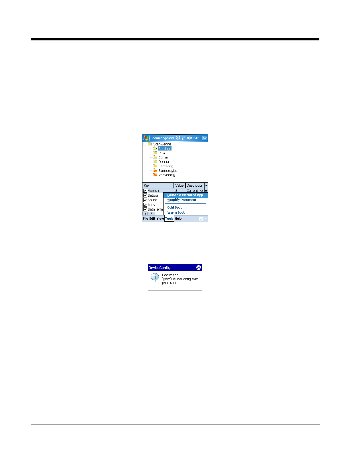
Launching DeviceConfig.exe Manually
DeviceConfig.exe does launch automatically after each cold boot. However, if you make changes to the
DeviceConfig.exm file that you want applied in the terminal immediately, manually launch
DeviceConfig.exe.
1. Tap Start > Power Tools > EZConfig Utilities > DeviceConfig.exm.
On the Dolphin 6100/6500/7600, tap Start > Programs > Power Tools > EZConfig Utilities >
DeviceConfig.exm
The DeviceConfig.exm file opens in EZConfig Editor.
2. Tap Tools > Launch Associated App.
3. The settings in the DeviceConfig.exm file are saved and applied to the terminal configuration by
DeviceConfig.exe.
4. A message appears confirming that DeviceConfig.exe has finished processing the
DeviceConfig.exm file.
Temporary Option for Bar Code Deployment
The Bar Codes Tab (see page 2-20) in EZConfig Editor contains a Temporary option (see page 2-22)
that, when selected during bar code creation, applies the settings in the DeviceConfig.exm file
temporarily, which means until the next cold boot.
In the terminal, EZConfig Client deploys the DeviceConfig.exm file and launches DeviceConfig.exe, which
applies the settings in the DeviceConfig.exm file as usual. However, when the Temporary option is
selected, the DeviceConfig.exm file is not saved after processing is finished. The original file is preserved
instead, and its settings will be restored during the next cold boot.
Select this option when you want establish a temporary configuration in the Dolphin (such as access to a specific
network in a facility) without changing the default configuration.
3 - 17
Page 68

3 - 18
Page 69
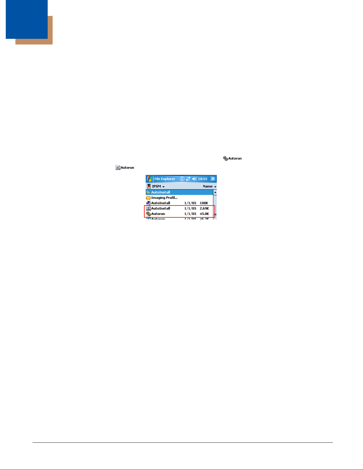
4
Startup Power Tools
Overview
Startup is the launch sequence when a Dolphin terminal is booted.
There are two startup Power Tools:
1. Autorun (see page 4-1)
2. AutoInstall (see page 4-7)
Autorun
Autorun specifies the software applications to launch after each hard reset. Autorun is located in the \IPSM
(\Honeywell for 6100/6500) folder and consists of an Autorun.exe that is programmed by the
Autorun.exm File (page 4-1) .
During startup, after a soft or hard reset, the operating system looks for and launches
(\Honeywell for 6100/6500). If the Autorun.exe is configured (by Autorun.exm) to launch an application,
that application launches when Autorun.exe launches. Autorun can launch up to 32 applications or utility
programs after each hard reset.
Note: The Autorun.exm file allows applications to be launched based on conditional situations, including the return
code of another application launched previously and specific characteristics of the Dolphin terminal itself.
\IPSM\Autorun.exe
Autorun.exm File
The Autorun.exm file has a multi-level tree structure. There are two top level sections: Settings and
Programs.
Settings Section
The Settings section stores general Autorun settings.
•See Settings Section Keys—Dolphins 7850, 7900, & 9500 on page 4-2.
•See Settings Section Keys—Dolphin 6100/6500/7600 on page 4-2.
Programs Section
The Programs section contains many child sections and determines the sequence of events at startup,
including which programs launch and when.
Program Sections and Launch Sequence
Each section is a program to launch at startup. The sequence of sections determines the launch
sequence on the terminal; the terminal reads this file consecutively. To change the launch sequence,
move the section up or down in the list; see Working with Sections (page 2-7).
4 - 1
Page 70

Enabling and Disabling Sections
If you don’t want to the application to launch at startup, you can delete the section. However, program
sections contain settings you’ll want to keep when adding that same application back to startup. To keep
the program section in the file for future reference, disable the program section instead of deleting it.
Disabled sections appear in gray.
When processing files, the terminal behaves as though disabled sections are not there and moves on to
the next enabled section.
Settings Section Keys—Dolphins 7850, 7900, & 9500
Note: This section and most of its keys are locked, which means that you can change the value but not the name
or description.
Key Function Default Available Values
Version Stores the EXM file version.
ByPassKey Defines the key that can be pressed to bypass
Autorun
StartMenu Enables and disables the Start menu during
Autorun
Debug Controls the debug function at AutoInstall.
TestMode Runs the terminal in test mode and tests the
functionality of AutoInstall. This is a diagnostic tool.
When enabled, applications stored in the
AutoInstall folder, including the radio drivers, are
not loaded during startup.
EZConfigKey Specifies a key that launches EZConfig Client
before Autorun starts processing the Programs
section; i.e., before Autorun starts launching
programs.
22
You cannot modify this
value!
42=SCAN
key
1
00=Disable
00=Disable
9=Tab key Empty=You must launch
0=Disable; the Start menu
is disabled during
Autorun.
1=Enable; the Start menu
is enabled.
1=Enable, an autorun.log
file is created in the
\IPSM folder.
1=Enable
EZConfig Client to scan
bar codes from
EZConfig Editor
Settings Section Keys—Dolphin 6100/6500/7600
Note: This section and most of its keys are locked, which means that you can change the value but not the name
or description.
Key Function Default Available Values
Version Stores the EXM file version.
4 - 2
22
You cannot modify this
value!
Page 71

Key Function Default Available Values
StartMenu Enables and disables the Start menu during
1
Autorun
Debug Controls the debug function at AutoInstall.
TestMode Runs the terminal in test mode and tests the
00=Disable
00=Disable
functionality of AutoInstall. This is a diagnostic tool.
When enabled, applications stored in the
AutoInstall folder, including the radio drivers, are
not loaded during startup.
MaskPassword If a password is entered in the Password key, this
10=Disable
key determines if that password is masked when
entered on the screen.
Programs’ Subsections—Dolphins 7850, 7900, & 9500
Here are a few of the standard child sections of the Programs section:
Section Description
0=Disable; the Start menu
is disabled during
Autorun.
1=Enable; the Start menu
is enabled.
1=Enable, an autorun.log
file is created in the
\IPSM
for 6100/6500)
1=Enable
1=Enable
(\Honeywell
folder.
Update Attempts to launch an Update.exe application from the SD (Secure Digital) card, if one exists.
AutoRun
SC1 & SC2
Attempts to process an Autorun configuration file from the SD card (if one exists); for example,
to install CAB files from the AutoInstall folder in the SD card. One section applies to cold boots
and the other to warm boots.
Reset Initiates a warm boot after the cold boot during startup. Do NOT disable the Reset section!
Note: Other subsections launch the executable entered in the Program (see page 4-3) key.
Keys in Each Programs’ Subsection—Dolphins 6100, 6500, 7600, 7850, 7900, & 9500
Each Programs’ subsection contains or can contain the following keys:
Key Function
Required Keys—These keys must be present in each Program subsection.
Program Specifies the command line to execute. This is the location of the program’s
Args Specifies the command line arguments to execute at startup.
executable. If you want a Power Tool to launch at startup, enter the location of that
tool’s EXE here.
4 - 3
Page 72
Key Function
Wait Determines if Autorun should wait for the program to complete and close before
continuing to the next program in the sequence.
• 0=Continue to the next program immediately
• 1=Wait enabled
StartOption Specifies the startup options for the program. Autorun launches the program only if
the startup options entered here are met.
• Blank= Always run the program.
• X=See Start Options on page 4-5.
Optional Keys—These are keys you can add but don’t appear in the default file.
PNPID Specifies a card description. This option needs to be entered only when PNPID or
NONPNPID values are specified in the StartOption key.
DependIndex Specifies the index of a dependent program.
DependExitCode Specifies the required result of the dependent program. If the result of the
dependent program does not equal the DependExitCode entered here, the current
program will not be executed at startup.
Editing the Autorun.exm File
Edit Autorun.exm in EZConfig Editor. For details, see Working with Open EXM Files on page 2-7.
Adding a Program Subsection
To launch at startup, a new program must be a child section of the Programs section.
1. In EZConfig Editor, right click on the Programs section and select Append Child Section.
2. On the Add New Section window, enter the Name and Description and click OK.
3. The new section is added to the bottom of the list.
4. Use the click and drag method to move the section to the desired launch sequence.
Press and hold the ALT key to make sure that you move the section at the same level. Do
not
append the section to an existing section!
5. Right-click in the key area and select Append Key. You must add all the required Autorun keys; see
Keys in Each Programs’ Subsection—Dolphins 6100, 6500, 7600, 7850, 7900, & 9500 on page 4-3.
6. Save the file and transport it to the terminal.
Copying a File
If you want to copy a file and move it to another location, use AutoInstall and the /copy command line
argument. For details, see Command Line Arguments on page 4-8.
4 - 4
Page 73

Sample Autorun Configuration File
A sample Autorun.exm file installs on the workstation to C:\Program Files\Honeywell\Power Tools and
Demos for WM 5.0\EZConfig EXM Files.
For more information, see Sample EXM Files on page 2-2.
Start Options
Start Options define the required system parameters for a software application to launch. The following values can be entered
for the StartOption key, wherever it appears:
Option Name The program launches if … Category
DISABLED Never, regardless of other startup options specified.
COLDBOOT The terminal has performed a cold boot.
WARMBOOT The terminal has performed a warm boot.
TOUCH The terminal has a touch screen display installed.
NONTOUCH The terminal doesn’t have a touch screen display installed.
BATCH The terminal is a batch unit (no RF or internal modem cards
installed).
RF The terminal has an RF card installed (e.g., Cisco 802.11b).
GSM The terminal has a GSM radio.
BT The terminal has a Bluetooth radio.
MODEM The terminal has an internal modem card installed.
IMAGER The terminal has an imager installed.
LASER The terminal has a laser scanner installed.
BLIND The terminal has no laser or imager installed.
None
Boot type
Touch screen
Mobility
Scanner
ANYSCAN The terminal has either an imager or a laser scanner installed.
RFON RF Radio is Enabled.
GSMON GSM is enabled.
BTON Bluetooth is enabled.
RFGSMBTOFF RF, GSM, & Bluetooth are disabled.
4 - 5
Page 74

Start Options
Start Options define the required system parameters for a software application to launch. The following values can be entered
for the StartOption key, wherever it appears:
Option Name The program launches if … Category
35KEY The terminal has a 35-key keyboard installed.
43KEY The terminal has a 43-key keyboard installed.
56KEY The terminal has a 56-key keyboard installed.
7600 The terminal is a Dolphin 7600.
7850 The terminal is a Dolphin 7850.
9500 The terminal is a Dolphin 9500.
9501 The terminal is a Dolphin 9501.
9550 The terminal is a Dolphin 9550.
9551 The terminal is a Dolphin 9551.
95XX The terminal is a Dolphin 9500, 9501, 9550, or 9551.
7900 The terminal is a Dolphin 7900.
PNPID The terminal has a card installed whose identification contains
ALL of the strings specified in the PNPID setting.
NONPNPID The terminal doesn’t have a card installed whose identification
contains ALL of the strings specified in the PNPID setting.
Keyboard
Model
Expansion Card
Multiple options can be specified for each category. For example, you can specify both 35KEY and
43KEY options to request that the program run in either a 35- or 43-key keyboard terminal. Seperate
multiple options with commas.
To ignore a category, don’t specify any of its options.
Applying Startup Options to the Autorun Configuration File
For each category, Autorun validates each startup option specified in the StartOption key. If no specified
option is valid in a category, Autorun does not execute the program. If at least one of the specified options
is valid in each category evaluated, the program is executed.
To always execute a program, specify no options in the StartOption key.
4 - 6
Page 75
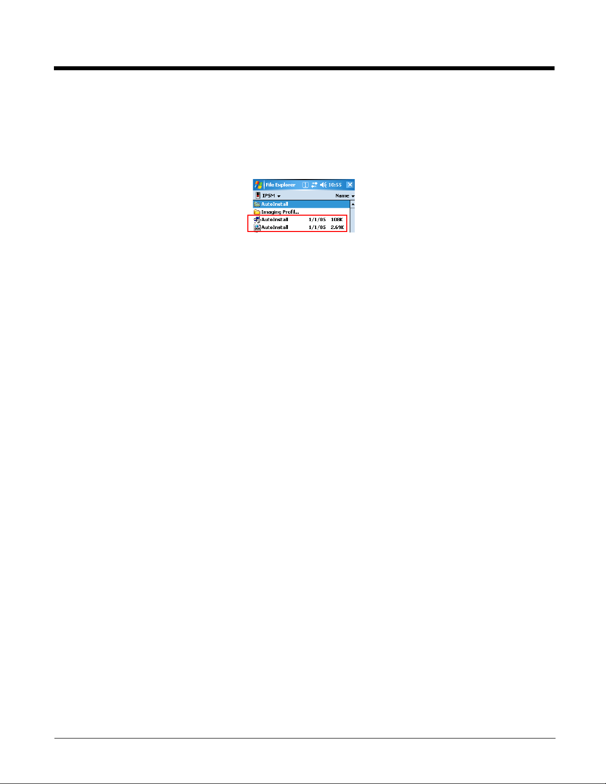
AutoInstall
AutoInstall consists of an AutoInstall.exe that, when launched, installs the cab files in the AutoInstall
folder. The AutoInstall folder is where you store cab files for software applications if you want them to
persist through hard resets.
Note: Cab files on the 6100/6500 are deleted from the Autoinstall folder after they are successfully installed.
The AutoInstall program runs according to the settings in the AutoInstall.exm file.
Program Install Locations
When triggered by a reset, the CAB file installs the applications to the directories established in the CAB
file. For most applications, this means that an EXE for the software application is placed in the \Program
Files
folder.
4 - 7
Page 76
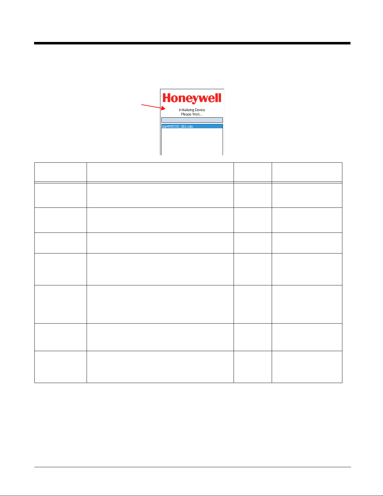
AutoInstall.exm
AutoInstall
window
The AutoInstall.exm file controls the behavior and appearance of the Autoinstall window and install
process.
Key Function Default
Available Values
Value
Version This is the current version of the AutoInstall.exm
3N/A
file.
This key is read-only and cannot be modified.
Debug Enable and disables logging of debug information
to
\IPSM\AUTOINSTALL.LOG (\Honeywell for
0
0=Disabled
1=Enabled
6100/6500).
Cancel Enable and disables the Cancel button on the
AutoInstall window.
FullScreen Determines if the AutoInstall window runs in full
screen mode (barring access to other windows).
HaltOnError Sets the behavior of AutoInstall when an error is
encountered.
MaskPassword If a password is entered in the Password key, this
key determines if that password is masked when
0
1
1
1
0=Disabled
1=Enabled
0=Disabled
1=Enabled
2=Autoselects based on
the operating platform.
0=Log the error and
continue AutoInstall
1=Halt AutoInstall and
prompt the user to
continue or cancel
0=Disabled
1=Enabled
entered on the screen.
Password Establishes a password required to halt
AutoInstall.
Blank
Blank=User can halt and
exit AutoInstall without
entering a password
X=Password
Note: Remember! It’s the Autorun.exm file that determines the programs and install sequence, not AutoInstall.exm.
Command Line Arguments
/copy Add /copy to the Autorun.exm file to automatically move a file from one location to another.
Usage autoinstall /copy <sourcefilename> <destination>
Example autoinstall /copy "/windows/data.mdf" "/storage card/data.mdf"
4 - 8
Page 77
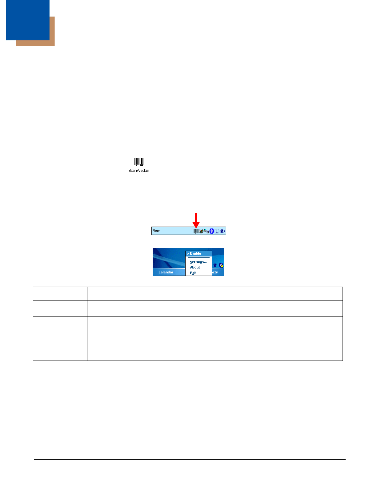
5
ScanWedge
Overview
ScanWedge sends data from the Dolphin decoder, serial port, or IrDA interface to the foreground
application as keystrokes (as if the data were entered via the keyboard). The foreground application is
the open software application whose window is currently active on the display.
As a result, you can review input data in Windows Mobile applications such as Pocket Word, Pocket
Excel, and Inbox without having to load third-party applications.
Enabling ScanWedge
Tap the ScanWedge icon once . ScanWedge initializes and enables.
Command Bar Menu
When ScanWedge is enabled, a smaller ScanWedge icon appears in the command bar at the bottom of
the Today screen.
Tap this icon to open the command bar menu.
Menu Item This item …
Enable Enables and disables ScanWedge without exiting ScanWedge.
Settings Opens the ScanWedge.exm file in EZConfig Editor.
About Opens the About screen for ScanWedge.
Exit Exits ScanWedge. The icon no longer appears in the Command bar.
Enabling ScanWedge at Startup
To run ScanWedge automatically when the Dolphin terminal boots up,
Add a link to the Scanwedge.exe in the
OR
Enable the ScanWedge section of the Autorun.exm File (see page 4-1).
\WINDOWS\STARTUP folder
5 - 1
Page 78

Disabling ScanWedge
Navigate to the Dolphin Power Tools Main Window (see page 1-2) and tap the ScanWedge icon again.
OR
Select Exit on the Command Bar Menu (page 5-1).
Modifying the ScanWedge Configuration File
When ScanWedge is installed, a ScanWedge.exm file is inserted in the \IPSM (\Honeywell for 6100/6500)
(\Honeywell for 6100/6500)
be located in the
\IPSM (\Honeywell for 6100/6500) directory. Do not move ScanWedge.exm!
folder. This file specifies configuration parameters for ScanWedge and must
Use EZConfig Editor on the workstation to modify ScanWedge.exm. For more information, see Working
with Open EXM Files on page 2-7.
ScanWedge.exm Sections
Section Description See
Page
Settings Programs general settings for ScanWedge. 5-3
Comm Specifies how the serial (RS-232) port interfaces with ScanWedge. 5-6
Decode Specifies how the decoder/scanner interfaces with ScanWedge. 5-9
Centering Defines the centering window for scanning bar codes when ScanWedge
is interfacing with the decoder.
Formatting Defines data formatting functionality. 5-13
Symbologies Defines the symbologies that the scanner can decode and send to
ScanWedge.
VK Mapping Defines the virtual key sent to ScanWedge for any decoded ASCII
character.
5-12
5-18
5-21
Basic Values
In each section, the following values apply (unless otherwise specified in the tables below):
0 = Disable
1 = Enable
5 - 2
Page 79

Settings Section
The Settings section determines how ScanWedge interprets data from the decoder, serial port, and IrDA
interface.
0 = Disable 1 = Enable
Settings Section
Description
Key
Version This is the version of ScanWedge 3
Debug Enables and disables the logging of debug
information to a SCANWEDGE.TXT file.
Sound Enables and disables the audio notification
for decode/data reception. There is one
sound for success and another sound for
an error.
Leds Enables and disables LED notification for
decode/data reception.
DataTerminator
Specifies the character to
recognize as the data
terminator when
receiving data from the
IrDA interface or serial
port.
When the data terminator character is
received, ScanWedge considers the data
received as successful, and sends the
specified prefix key + data received +
specified suffix key to the foreground
application.
Note: The data terminator character itself
will not be transmitted. If required,
put this character in the suffix.
Default
Val ue
0
1
1
13
Available Values
You cannot modify this value.
1=Enable. Debug data is logged in
a Scanwedge.txt file stored in the
(\Honeywell for
\IPSM
6100/6500)
0=Disable; no sound on decoding.
1=Enable; sound on decoding.
0=Disable; no LEDs on decoding.
1=Enable; LEDs on decoding.
Set to the desired character.
This parameter is ignored for the
decoder. The decoder knows when
the data ends by itself.
folder.
PrefixKeys Defines the ASCII keys to be sent prior to
the decoded/received data. The ASCII
keys are converted to virtual keys; for
conversion parameters, see Virtual Key
Codes Table on page 5-22.
This field supports up to 16 ASCII keys;
data is comma-delimited.
SuffixKeys Defines the ASCII keys to be sent after the
decoded/received data. The ASCII keys
are converted to virtual keys; for
conversion parameters, see Virtual Key
Codes Table on page 5-22.
This field supports up to 16 ASCII keys;
data is comma-delimited.
PrefixID Specifies the symbology identifier sent
prior to the decoded/received data.
0
Empty,
No
prefix
sent
13
ENTE
R key
0
For example:
PrefixKeys=80,82,69,70,73,88
The example listed above would
cause “PREFIX” to be sent prior to
any decoded data.
For example:
SuffixKeys=83,85,70,70,73,88,13
The example listed above would
cause “SUFFIX” and the ENTER
key to be sent after any decoded
data.
0=No symbology identifier is sent.
1=The Code ID is sent.
2=The AIM ID is sent.
3=The SymModifier is sent.
5 - 3
Page 80

Settings Section
The Settings section determines how ScanWedge interprets data from the decoder, serial port, and IrDA
interface.
0 = Disable 1 = Enable
Settings Section
Description
Key
SuffixID Specifies the symbology identifier sent
after the decoded/received data.
SoundConnect Enables and disables
• The sound that ScanWedge makes
when starting up, shutting down, or
restarting.
• The audio notification when an IrDA
session is established and closed and
the serial port is opened and closed.
MessageConnect
This key applies only to
the IrDA and serial ports.
Enable and disables a notification
message when an IrDA session is
established and closed and the serial port
is opened and closed.
Accept EZConfig
This key applies only to
the decoder.
Enables and disables ScanWedge’s
compatibility with EZConfig Client when
decoding bar codes.
Default
Val ue
0
1
0
1
Available Values
0=No symbology identifier is sent.
1=The Code ID is sent.
2=The AIM ID is sent.
3=The SymModifier is sent.
0=Disabled
1=Enabled
Audio notifications for errors can’t
be disabled.
0=Disabled
1=Enabled
0=Disabled; ScanWedge processes
EZConfig barcodes as it would
any other barcode.
1=Enabled; ScanWedge recognizes
EZConfig barcodes and passes
them on to the EZConfig Client
for further processing.
5 - 4
Page 81

Settings Section
The Settings section determines how ScanWedge interprets data from the decoder, serial port, and IrDA
interface.
0 = Disable 1 = Enable
Settings Section
Description
Key
SendMode Specifies the method to use when sending
the decoded message to the foreground
application.
Note: This setting affects only the decoded
message; the prefix and suffix are
always sent using the virtual key
method to allow navigational
functionality.
Note: This key does not appear in the
ScanWedge.exm file for the Dolphin
6100/6500/7600.
Default
Val ue
0
Available Values
0=Virtual key method: each
character is sent as a virtual
keystroke. This method works
well with almost any Windows
Mobile or Windows CE
application.
1=Direct Text method: the decoded
message is sent as text directly
to the window that has the
keyboard focus in the foreground
application. This method is faster
than the virtual key and supports
barcodes with ASCII characters
between 1 and 255 but works
only if the foreground application
uses standard Window’s Edit
controls for user input.
2=Virtual Key (safe) method: each
character is sent as a virtual
keystroke using
PostKeybdMessage().
This method only support bar
codes containing ASCII
characters and does not support
VKMapping. This method only
generates WM_CHAR
messages, it does not generate
WM_KEYDOWN and
WM_KEYUP messages.
GoodScanWav Specifies a .wav file played on the
completion of a successful decode/data
reception.
BadScanWav Specifies a .wav file played for an
unsuccessful decode/data reception.
Empty
Empty
Empty=No .wav file is specified.
The default beep or sound is
played. Use the Sound (page 5-
3) key to enable and disable all
audio notification.
X=The path to the specific .wav file
you want played for either option.
The .wav files should be 8-bit,
11KHz, mono, and PCM.
5 - 5
Page 82

Comm Section
The serial port settings in the Comm section determine the interaction between ScanWedge and the serial
port.
Comm Section
Description Default
Key
Enable
Enables (or disables) ScanWedge to
receive and interpret data from the
serial port.
AutoConnect
Enables or disables the autoconnection between ScanWedge
and the serial port.
Port Specifies the serial port to use to
connect to ScanWedge.
Note: This setting is ignored for Port 4.
FlowControl Specifies the flow control method to
use–software only, hardware only, or
software and hardware.
Note: This setting is ignored for Port 4.
Value
0
0
7900=1
9500=1
4
Available Values
0=Disabled; no data is received
1=Enabled; ScanWedge receives data
from the serial port (specified in the
Port key) as keystrokes to the
foreground application.
0=Disabled; ScanWedge opens the
serial port immediately at startup and
doesn’t close until ScanWedge is
closed. This is the recommended
setting when the serial port is port 2
or 3.
1=Enabled; ScanWedge connects to the
serial port when a power source is
detected and disconnects when the
power source is removed/not
detected.
The use of port 4/6 is not encouraged.
See Dolphin 7900/9500 Port Tables
on page 5-8.
1=Software (Xon-Xoff)
2=Hardware
3=Hardware and software
4=No flow control
BaudRate Specifies the baud rate for the serial
port.
Note: This setting is ignored for Port 4.
Parity Specified the parity for the connection.
Note: This setting is ignored for Port 4.
DataBits Specifies the number of bits per byte to
use.
Note: This setting is ignored for Port 4.
StopBits Specified the number of stop bits to
use.
Note: This setting is ignored for Port 4.
5 - 6
38400
0
8
0
X=The appropriate baud rate.
0=No parity
1=Odd parity
2=Even parity
3=Mark parity
4=Space parity
X=Number of bits per byte
0=1 stop bit
1=1.5 stop bits
2=2 stop bits
Page 83

Comm Section
The serial port settings in the Comm section determine the interaction between ScanWedge and the serial
port.
Comm Section
Description Default
Key
Powerout Enables and disables power out of the
serial port for ScanWedge specifically.
General power out settings are
established in the registry.
The serial port powers out 5V at
500mA.
This parameter is supported for all
software configurations of the Dolphin
7900 and for the following software
configurations of the Dolphin 9500:
• Kernel 7.01, SP8 or later
• Kernel 7.03, SP1 or later (Kernel 7.03
alone is not supported.)
EnablePrefixData Enables or disables all prefix data
received via COM port after a
successful scan.
All prefix data is defined in the Settings
Section (see page 5-3).
EnableSuffixData Enables or disables all suffix data
received via COM port after a
successful scan.
All suffix data is defined in the Settings
Section (see page 5-3).
Value
0
0
0
Available Values
0=Disabled; do not power out when
scanning with ScanWedge
1=Enabled; power out when scanning
with ScanWedge.
2=No change for ScanWedge. This
means that ScanWedge is not altering
the default power out setting in the
registry. The terminal defaults to the
power-out setting in the registry.
0=Disabled
1=Enabled
0=Disabled
1=Enabled
5 - 7
Page 84

Dolphin 7900/9500 Port Tables
7900
Port
11Mini-RS-232, RS-232
22Bluetooth module–If there is no Bluetooth
33Raw infrared (IR)
44Unassigned
55USB virtual serial port
66IrDA port
7,8,9 7,8,9 Unassigned–These are virtual COM ports
9500
Port
Interface
hardware installed on the terminal, this
COM port is unassigned.
available for selection only when
connecting to devices that use virtual COM
ports, such as Bluetooth devices.
5 - 8
Page 85

Decode Section
The Decode section specifies decoder settings when using the decoder with ScanWedge.
ScanWedge Entry Description Default
Value
Enable Enables and disables the decoder for
1
ScanWedge.
Trigger Sets the key used by ScanWedge to
42
initiate a scan/decode. The key is
registered as a system hotkey and
cannot be registered as a hot key by
any other applications.
ContScan Enables and disables continuous
0
scan.
PowerSave Enables and disables power saving
1
mode.
Note: This key does not appear in the
ScanWedge.exm file for the
Dolphin 6100/6500/7600.
Available Values
0=Disabled; decoder is not used.
1=Enabled; decoder sends bar
code data as keystrokes to the
active window.
42=OnScan or Scan key
0=Disabled; trigger key must be
released between scans.
1=Enabled; data is continuously
decoded and sent to the
application while the trigger key
is depressed.
1=Enabled; the decoder
automatically initializes and uninitializes as needed. A slight
delay occurs when the trigger is
activated.
0=Disabled; the decoder initializes
when the utility starts and uninitializes when the utility
terminates.
ScanTimeout Specifies the decode time out in 1/
1000th seconds. If a barcode is not
decoded within the specified timeout
an audio and visual notification
indicates that an error occurred.
ScanMode Specifies the decode mode. 1
LinearRange Specifies the linear search range to
be used while in ALD mode.
5000
3
X=Time in 1/1000th of a second.
1=Full Omni/Normal
2=ALD (Aggressive Linear
Decode) mode
4=Quick Omni
X=Range from 1 to 6.
1 indicates a tight vertical range
near the aimer.
6 indicates a vertical range of
the entire height of the imager.
5 - 9
Page 86

Decode Section
The Decode section specifies decoder settings when using the decoder with ScanWedge.
ScanWedge Entry Description Default
Value
AimerDuration The number of milliseconds the
scanner aimer is displayed, after the
trigger key has been pressed down,
before attempting to decode a
barcode.
AimerDelay The amount of time between scans
0
[Decode
begins
instantly.
]
500
before the aimer turns on again.
AimerDurationALR The amount of time the aimer stays
2000
on. This setting is for an ALR
decoder.
AimerDelayALR The amount of time between scans
500
before the aimer turns on again.
This setting is for an ALR decoder.
DefaultEnabledSymbo
logies
Specifies which symbologies should
be enabled before processing the
Symbologies section; see
0
Symbologies Section on page 5-18.
Available Values
Enter times in 1/1000th of a
second.
0=Use internal list
1=All symbologies are disabled
initially. Enable specific
symbologies in the Symbologies
section.
2=All symbologies are enabled
initially. Disable specific
symbologies in the Symbologies
section.
EnablePrefixData Enables or disables all prefix data
received from the decoder after a
successful scan.
All prefix data is defined in the
Settings Section (see page 5-3).
EnableSuffixData Enables or disables all suffix data
received via decoder after a
successful scan.
All suffix data is defined in the
Settings Section (see page 5-3).
5 - 10
1
1
0=Disabled
1=Enabled
0=Disabled
1=Enabled
Page 87

Decode Section
The Decode section specifies decoder settings when using the decoder with ScanWedge.
ScanWedge Entry Description Default
Value
GoodScanFreq Sound frequency used for play a
2749
custom good scan beep.
The Window's "Good Decode" sound
(if defined in the control panel) takes
precedence over this option.
GoodScanLen Number of milliseconds to play the
50
sound as specified in GoodScanFreq
key.
BadScanFreq Sound frequency used for play a
523
custom bad scan beep.
The Window's "Bad Decode" sound
(if defined in the control panel) takes
precedence over this option.
BadScanLen Number of milliseconds to play the
25
sound as specified in BadScanFreq
key.
Available Values
Var iabl e
Use the up and down arrows to
change the number
OR
Type in the code for the sound you
want.
5 - 11
Page 88

Centering Section
The Centering section determines the centering window for bar code scanning.
ScanWedge Entry Description Default
Value
CenteringEnable= Enable and disables the decode
centering window for the decoder.
0
Available Values
0=Disabled; centering is disabled
for ScanWedge.
1=Enabled; bar codes are decoded
only if they are within the
centering window specified by
the rest of the keys in this
section.
Note: On Dolphins 7850, 7900, & 9500, the keys in this section are disabled by default.
CenteringTop=
Specifies the top coordinate of the
210 Enter the coordinates in pixels.
centering window.
CenteringBottom=
Specifies the bottom coordinate of
270
the centering window.
CenteringLeft=
Specifies the left coordinate of the
346
centering window.
CenteringRight=
Specifies the right coordinate of
406
the centering window.
5 - 12
Page 89

Formatting
ScanWedge supports data formatting. The Formatting section contains subsections. Each subsection
supports one data format.
Formatting Subsections
Subsection
Key
Format Specifies data formatting parameters Empty
CodeID Identifies the Hand Held Products Code ID that
Length Determines the length the bar code data must
Description
the bar code's symbology must have for the
format to be applied. The Code ID is a single
character that is case-sensitive; e.g., set
CodeID=j to apply the format to Code 128 only.
have for the format to be applied.
Default
Val ue
Empty
Empty
Available Values
See Available Data Formatting
Commands on page 5-13.
Empty=No Code ID
X=See Code ID on page 5-15.
Empty=Format applies to any
length
0=Format applies to any length
X=The length
Available Data Formatting Commands
These are the data formatting operations applied to the bar code data. The entire command string is
entered into the Format key.
Command Description
Send Commands
F1xx Send all characters followed by “xx” key or function code, starting from current cursor
position.
F2nnxx Send “nn” characters followed by “xx” key or function code, starting from current cursor
position.
F3ssxx Send up to but not including “ss” character (Search and Send) starting from current
cursor position, leaving cursor pointing to “ss” character followed by “xx” key or function
code.
F4xxnn Send “xx” character “nn” times (Insert) leaving cursor in current cursor position.
E9nn Send all but the last “nn” characters, starting from the current cursor position.
Move Commands
F5nn Move the cursor ahead “nn” characters from current cursor position.
F6nn Move the cursor back “nn” characters from current cursor position.
F7 Move the cursor to the beginning of the data string.
5 - 13
Page 90

Available Data Formatting Commands
These are the data formatting operations applied to the bar code data. The entire command string is
entered into the Format key.
Command Description
EA Move the cursor to the end of the data string.
Search Commands
F8xx Search ahead for “xx” character from current cursor position, leaving cursor pointing to
“xx” character.
F9xx Search back for “xx” character from current cursor position, leaving cursor pointing to
“xx” character.
E6xx Search ahead for the first non “xx” character from the current cursor position, leaving
cursor pointing to non “xx” character.
E7xx Search back for the first non “xx” character from the current cursor position, leaving
cursor pointing to non “xx” character.
Miscellaneous Commands
FExx Compare character in current cursor position to the character “xx.” If characters are
equal, increment cursor. If characters are not equal, no format match.
EC Check to make sure there is an ASCII number at the current cursor position.If character
is not numeric, format is aborted.
ED Check to make sure there is a non-numeric ASCII character at the current cursor
position. If character is numeric, format is aborted.
FBnnxxyy…zz Suppress all occurrences of up to 15 different characters, starting at the current cursor
FC Disables suppress filter and clear all suppressed characters.
E4nnxx1xx2yy1
yy2…zz1zz2
E5 Terminates character replacement.
position, as the cursor is advanced by other commands. When the FC command is
encountered, the suppress function is terminated. The cursor is not moved by the FB
command. nn is a count of the number of suppressed characters in the list and xxyy…zz
is the list of characters to be suppressed.
Replaces up to 15 characters in the data string with user specified characters.
Replacement continues until the E5 command is encountered. nn is the total count of
both characters to be replaced plus replacement characters; xx1 defines characters to
be replaced and xx2 defines replacement characters, continuing through zz1 and zz2.
Note: xx and ss stand for hex values of a character (00-FF), nn for a numeric count (00-99).
5 - 14
Page 91

Code ID
Symbology Name ID
Australian Post A (0x41)
Aztec Code z (0x7A)
Aztec Mesa Code Z (0x5A)
British Post B (0x42)
Canadian Post C (0x43)
China Post Q (0x51)
Codabar a (0x61)
Codablock F q (0x71)
Code 11 h (0x68)
Code 128 j (0x6A)
Code 16K o (0x6F)
Code 32 Pharmaceutical (PARAF) < (0x3C)
Code 39 b (0x62)
Code 49 l (0x6C
Code 93 and 93i i (0x69)
Coupon Code c (0x63)
Data Matrix w (0x77)
EAN·UCC Composite y (0x79)
GS1-128 I (0x49)
EAN-13 d (0x64)
EAN-8 D (0x44)
Grid Matrix X (0x57)
Han Xin H (0X48)
Interleaved 2 of 5 e (0x65)
5 - 15
Page 92

Code ID
Symbology Name ID
ISBT j (0x6A)
Japanese Post J (0x4A)
KIX (Netherlands) Post K (0x4B)
Korea Post ? (0x3F)
Matrix 2 of 5 m (0x6D)
MaxiCode x (0x78)
MicroPDF417 R (0x52)
MSI g (0x67)
OCR US Money Font,
MICR (E 13 B) and SEMI Font
OCR-A O (0x4F)
OCR-B O (0x4F)
PDF417 r (0x72)
Planet Code L (0x4C)
Plessey Code n (0x6E)
PosiCode W (0x57)
Postnet P (0x50)
QR Code s (0x73)
Reduced Space Symbology
(RSS-14,RSS Limited, RSS
Expanded)
Straight 2 of 5 IATA (two-bar start/
stop)
O (0x4F)
y (0x79)
f (0x66)
Straight 2 of 5 Industrial
(three-bar start/stop)
TCIF Linked Code 39 (TLC39) T (0x54)
Telepen t (0x74)
f (0x66)
5 - 16
Page 93

Code ID
Symbology Name ID
Trioptic Code = (0x3D)
UPC-A c (0x63)
UPC-E0 E (0x45)
UPC-E1 E (0x45)
5 - 17
Page 94

Symbologies Section
The Symbologies section specifies the settings for each of the symbologies supported by the decoder.
The settings are in the form:
Symbology Name=Enable(1 or 0), Parm1, Parm2, Parm3, Parm4, Parm5, Parm6, Parm7,
Parm8
Where
• Enable specifies that the symbology is enabled or disabled.
• Parms1–8 specify the settings for the symbology.
For more information regarding the individual settings for each of the symbologies, refer to the Dolphin
Decode API documentation in the Dolphin SDK documentation.
Symbologies Settings
0=Disabled 1=Enabled
ScanWedge Entry Default Enabled/
Disabled Value
Australian Post 0=Disabled 0,0,0,0,0,0,0,0,0
Aztec Code 1=Enabled 1,1,3750,0,0,0,0,0,0
Aztec Mesas
(This code is not available on
the Dolphin 6100/6500/7600.)
British Post 0=Disabled 0,0,0,0,0,0,0,0,0
Canadian Post 0=Disabled 0,0,0,0,0,0,0,0,0
China Post 0=Disabled 0,4,80,0,0,0,0,0,0
Codabar 1=Enabled 1,0,0,0,4,60,0,0,0
Codablock 0=Disabled 0,1,2048,0,0,0,0,0,0
Code 11 0=Disabled 0,1,4,80,0,0,0,0,0
Code 128/GS1-128 1=Enabled 1,0,80,0,0,0,0,0,0
0=Disabled 0,0,0,0,0,0,0,0,0
Default Value
Code 16K 0=Disabled 0,1,160,0,0,0,0,0,0
Code 32 0=Disabled 0,0,0,0,0,0,0,0,0
Code 39 1=Enabled 1,0,0,0,0,0,0,48,0
5 - 18
Page 95

Symbologies Settings
0=Disabled 1=Enabled
ScanWedge Entry Default Enabled/
Disabled Value
Code 49 0=Disabled 0,1,81,0,0,0,0,0,0
Code 93 0=Disabled 0,0,80,0,0,0,0,0,0
Coupon Code 0=Disabled 0,0,0,0,0,0,0,0,0
Data Matrix 0=Disabled 0,1,1500,0,0,0,0,0,0
Dutch Post 0=Disabled 0,0,0,0,0,0,0,0,0
EAN-8 0=Disabled 0,1,0,0,0,1,0,0,0
EAN-13 1=Enabled 1,1,0,0,0,1,0,0,0
EAN.UCC Composites 0=Disabled 0,1,300,0,0,0,0,0,0
Grid Matrix 0=Disabled 0,1,6000,0,0,0,0,0,0
Han Xin 0=Disabled 0,1,2751,0,0,0,0,0,0
Interleaved 2 of 5 1=Enabled 1,0,0,4,80,0,0,0,0
Default Value
ISBT 0=Disabled 0,0,0,0,0,0,0,0,0
Japanense Post 0=Disabled 0,0,0,0,0,0,0,0,0
Korea Post 0=Disabled 0,4,48,0,0,0,0,0,0
Matrix 2 of 5 0=Disabled 0,4,80,0,0,0,0,0,0
MaxiCode 0=Disabled 0,0,1,150,0,0,0,0,0
MicroPDF417 1=Enabled 1,1,366,0,0,0,0,0,0
MSI 0=Disabled 0,4,48,0,0,0,0,0,0
OCR 0=Disabled 0,2,dddddddd,,,,0
PDF417 1=Enabled 1,1,2750,0,0,0,0,0,0
Planet Code 0=Disabled 0,0,0,0,0,0,0,0,0
Plessey 0=Disabled 0,4,48,0,0,0,0,0,0
PosiCode 0=Disabled 0,4,48,2,0,0,0,0,0
5 - 19
Page 96

Symbologies Settings
0=Disabled 1=Enabled
ScanWedge Entry Default Enabled/
Disabled Value
Postnet 0=Disabled 0,0,0,0,0,0,0,0,0
QR Code 0=Disabled 0,1,3500,0,0,0,0,0,0
Reduced Space
Symbology (RSS)
Straight 2 of 5 IATA 0=Disabled 0,4,48,0,0,0,0,0,0
Straight 2 of 5
Industrial
TCIF Linked Code 39
(TLC39)
Telepen 0=Disabled 0,1,60,0,0,0,0,0,0
Trioptic Code 0=Disabled 0,0,0,0,0,0,0,0,0
UPC-A 1=Enabled 1,1,1,0,0,0,1,0,0
UPC-E0 0=Disabled 0,1,1,0,0,0,0,1,0
0=Disabled 0,4,74,0,0,0,0,0,0
0=Disabled 0,4,48,0,0,0,0,0,0
0=Disabled 0,0,0,0,0,0,0,0,0
Default Value
UPC-E1 0=Disabled 0,1,1,0,0,0,0,1,0
5 - 20
Page 97

VK (Virtual Key) Mapping Section
The virtual key map settings are located in the VKMapping section in the ScanWedge configuration file.
The virtual key map settings define the virtual key that will be sent to ScanWedge for any decoded ASCII
character.
The settings are in the form: ASCII Key = Virtual Key, ShiftMode
Where
• ASCII Key is an ASCII value between 0 an 255 (decimal)
• Virtual Key is the virtual key to be sent when the specified ASCII key is decoded
• ShiftMode can have the following values:
• 0=the virtual key is never shifted
• 1=the virtual key must be shifted
• 2=the virtual key needs to be shifted if Caps Lock is off
• 3=the virtual key needs to be shifted if Caps Lock is on
For detailed information about the values in this section, see Virtual Key Codes Table on page 5-22.
5 - 21
Page 98

Virtual Key Codes Table
The following table shows the symbolic constant names, hexadecimal values, and keyboard equivalents
for the virtual-key codes used by the Windows Mobile and Windows CE operating systems. The codes
are listed in numeric order.
Note: To use these codes in the VKMapping section, the hexadecimal values need to be converted to decimals.
Virtual Key Codes Table
Symbolic Constant
Name
VK_LBUTTON 1 01 Touch screen
VK_CANCEL 3 03 Control-break processing
—— 5-7 05-07 Undefined
VK_BACK 8 08 BACKSPACE key
VK_TAB 9 09 TAB key
—— 10-11 0A-0B Undefined
VK_CLEAR 12 0C CLEAR key
VK_RETURN 13 0D ENTER key
—— 14-15 0E-0F Undefined
VK_SHIFT 16 10 SHIFT key
VK_CONTROL 17 11 CTRL key
Decimal
Val ue
Hexadecimal
Val ue
Touch Screen or Keyboard Equivalent
VK_MENU 1812ALT key
VK_CAPITAL 20 14 CAPS LOCK key
—— 21-25 15-19 Reserved for Kanji systems
—— 26 1A Undefined
VK_CLEAR 12 0C CLEAR key
VK_RETURN 13 0D ENTER key
—— 14-15 0E-0F Undefined
VK_SHIFT 16 10 SHIFT key
VK_CONTROL 17 11 CTRL key
5 - 22
Page 99

Virtual Key Codes Table
Symbolic Constant
Name
VK_MENU 1812ALT key
VK_CAPITAL 20 14 CAPS LOCK key
—— 21-25 15-19 Reserved for Kanji systems
—— 26 1A Undefined
VK_ESCAPE 27 1B ESC key
—— 28-31 1C-1F Reserved for Kanji systems
VK_SPACE 32 20 SPACEBAR key
VK_PRIOR 33 21 PAGE UP key
VK_NEXT 34 22 PAGE DOWN key
VK_END 35 23 END key
VK_HOME 3624HOME key
Decimal
Val ue
Hexadecimal
Val ue
Touch Screen or Keyboard Equivalent
VK_LEFT 37 25 LEFT ARROW key
VK_UP 3826UP ARROW key
VK_RIGHT 39 27 RIGHT ARROW key
VK_DOWN 4028DOWN ARROW key
VK_SELECT 41 29 SELECT key
—— 42 2A Original equipment manufacturer
(OEM)– specific
VK_EXECUTE 43 2B EXECUTE key
VK_SNAPSHOT 44 2C PRINT SCREEN key for Windows 3.0 and
later
VK_HELP 47 2F HELP key
VK_0 48 30 0 key
VK_1 49 31 1 key
VK_2 50 32 2 key
5 - 23
Page 100

Virtual Key Codes Table
Symbolic Constant
Name
VK_3 51 33 3 key
VK_4 52 34 4 key
VK_5 53 35 5 key
VK_6 54 36 6 key
VK_7 55 37 7 key
VK_8 56 38 8 key
VK_9 57 39 9 key
—— 58-64 3A-40 Undefined
VK_A 65 41 A key
VK_B 66 42 B key
VK_C 67 43 C key
Decimal
Val ue
Hexadecimal
Val ue
Touch Screen or Keyboard Equivalent
VK_D 68 44 D key
VK_E 69 45 E key
VK_F 70 46 F key
VK_G 71 47 G key
VK_H 72 48 H key
VK_I 73 49 I key
VK_J 74 4A J key
VK_K 75 4B K key
VK_L 76 4C L key
VK_M 77 4D M key
VK_N 78 4E N key
VK_O 79 4F O key
VK_P 80 50 P key
5 - 24
 Loading...