

Dolmar 109, 110i, 111, 111i, 115i Service Manual
DOLMAR GmbH • Postfach 70 04 20 • D-2000 Hamburg 70 • Germany
Service Manual
2/93
DOLMAR 109
DOLMAR 110i
DOLMAR 111
DOLMAR 111i
DOLMAR 115i

2
Table of contents
Index Technical data Page 3
Special tools 4
01 Chain brake 5
02 Clutch, clutch drum 6
03 Oil pump 7
04 Ignition system 8
05 Starter assembly 10
06 Carburettor, intake system 11
07 Cover system, air filter 13
08 Vibration dampers, handle 14
09 Fuel tank 15
10 Cylinder and piston 16
11 Crankcase, crankshaft 17
12 Checking operations 18
Torques 19
DOLMAR GmbH
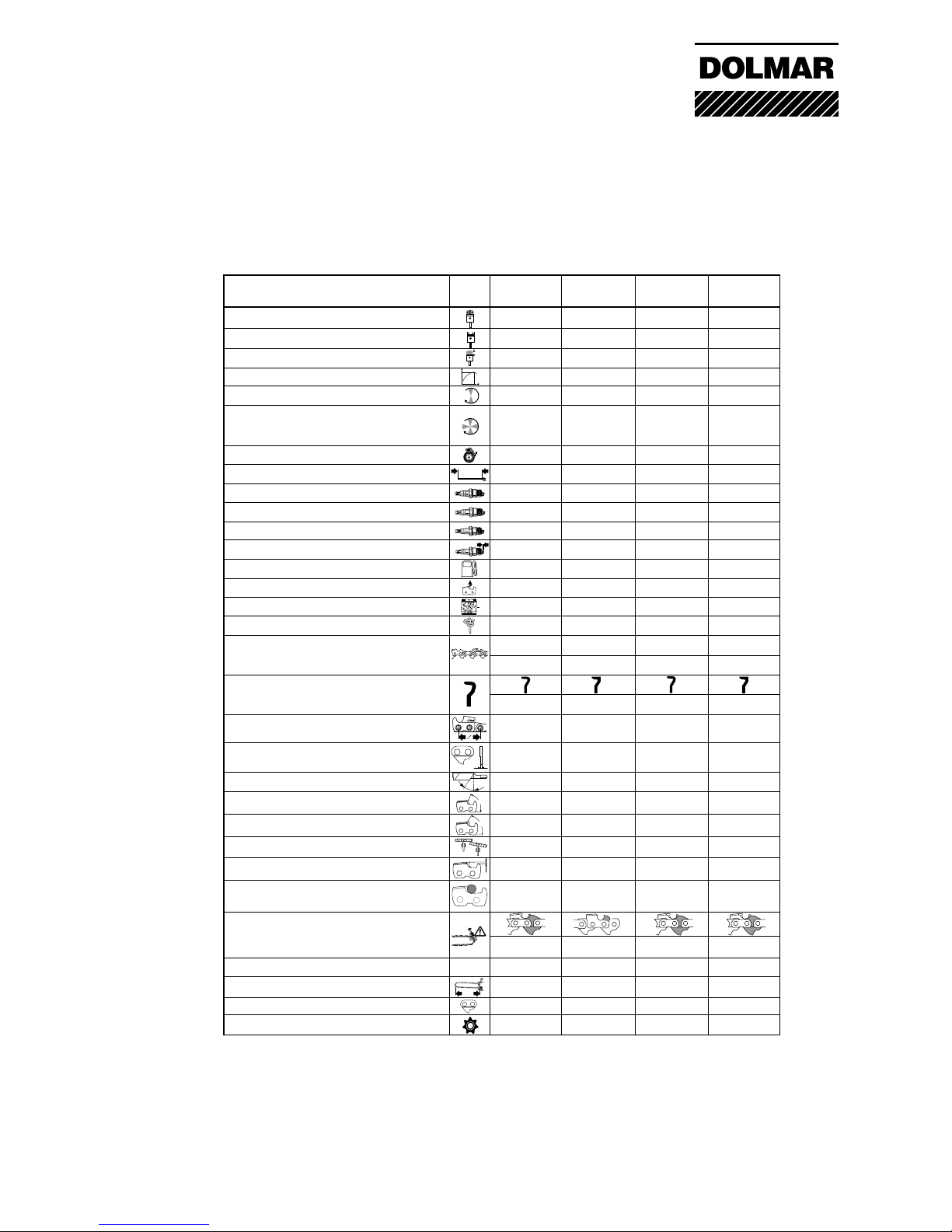
- Bumper Depth Gauge Bumper Bumper
Drive Link Drive Link Drive Link
Type Spur (fixed) Rim (loose) Spur (fixed) Rim (loose)
Cutting length cm 38 33/38 38 45
Drive Link count 56 56/64 56 64
Sprocket Z 7877
Model
109 110i 115i
Displacement cm
3
43 43 52 52
Bore mm 40 40 44 44
Stroke mm 34 34 34 34
Rating kW 2,0 2,3 2,4 2,7
Idling 1/min 2500 2500 2500 2500
Allowed max. engine speed
with bar and chain 1/min 12500 13200 12500 13000
(* with speed limitation)
Gap Flywheel / Coil mm 0,2-0,3 0,2-0,3 0,2-0,3 0,2-0,3
High tension wire length mm 180 180 180 180
Spark plug NGK BPMR-7A BPMR-7A BPMR-7A BPMR-7A
BOSCH WSR-6F WSR-6F WSR-6F WSR-6F
CHAMPION
Elektrode gap mm 0,5 0,5 0,5 0,5
Fuel tank capacity Ltr. 0,56 0,56 0,56 0,56
Oil tank capacity Ltr. 0,28 0,28 0,28 0,28
Carb. adjustment L / H 1/1 1/ 1 1/8 1/1 1/ 1 1/8
Starter rope ø / length mm 3,5 / 980 3,5 / 980 3,5 / 980 3,5 / 980
Saw chain Model 093 084 093 099
Normal profil Low profil Normal profil Low profil
Cutter type
Semi chisel Chisel Semi chisel Chisel
Gauge inch 3/8 .325 3/8 3/8
mm (9,52) (8,2) (9,52) (9,52)
Drive link inch 0.58 0.58 0.58 0.58
mm (1,5) (1,5) (1,5) (1,5)
Filling Angle 35° 30° 35° 25°
Side Angle 85° 75° 85° 60°
Cutting Angle 60° 60° 60° 60°
File Guide Angle 90° 10° 90° 90°
Depth Gage Setting mm 0,65 0,65 0,65 0,65
File ø mm 5,5 4,5 5,5 5,5
Technical data
Kick back reduction
r.p.m.
H
Max.
L
H
S
1
2
90°
10°
r.p.m.
L
From 1/2 Cutter mm 4,8 4,0 4,8 4,8
3
DOLMAR GmbH
111/111i
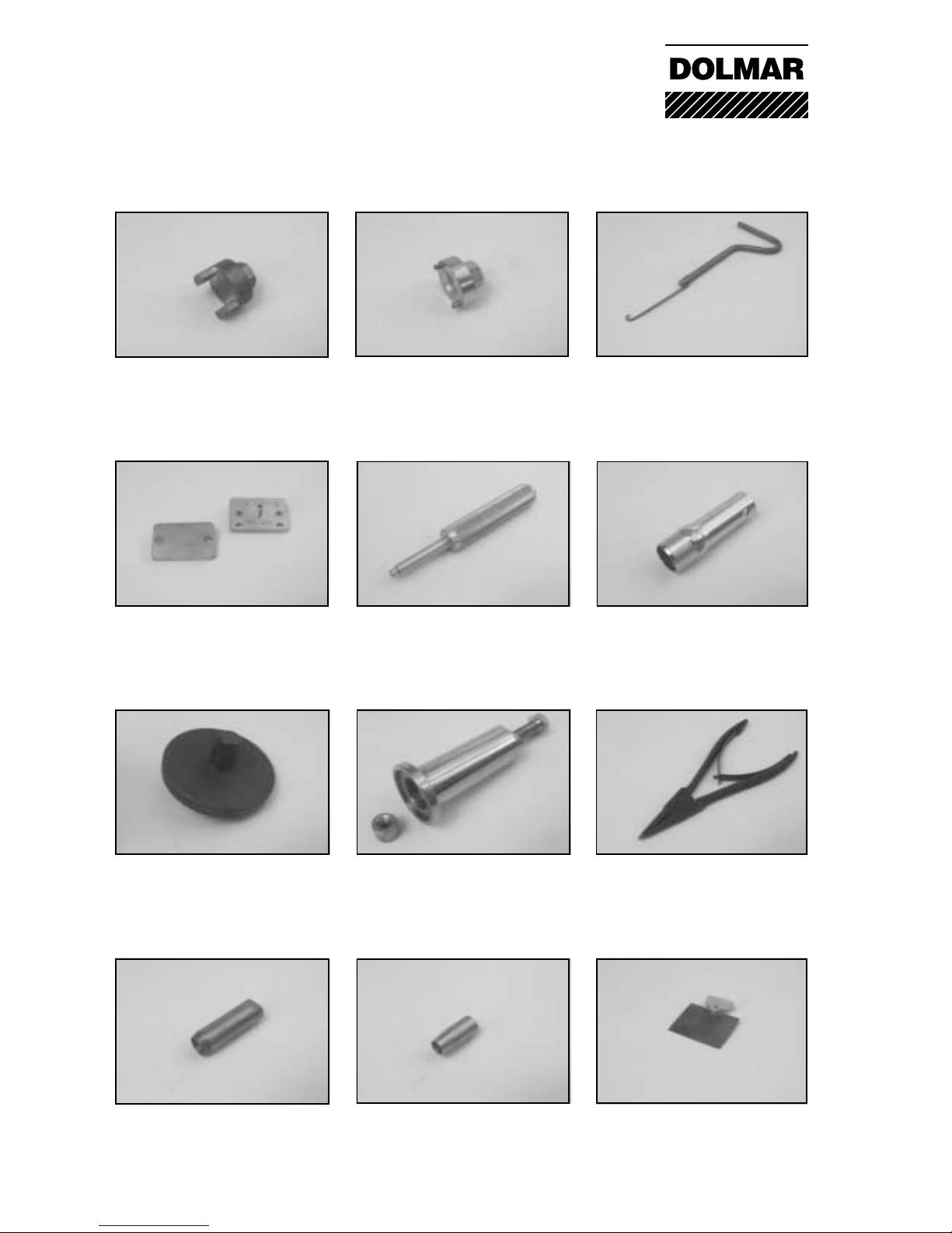
Special tools
Puller for tension spring
of chain brake
950 237 000
Mounting tool for
clutch hub
944 500 690
Mounting tool for
clutch hub
944 500 680
Special socket wrench
for rubber buffer
944 500 621
Drift for piston pin
944 603 260
Sealing plate for
leakage test of crankcase
944 603 020 / 944 603 030
Mounting for roler bearing
crankcase
950 500 050
Puller for drive worm
of oil pump
957 433 000
Snap ring pincer for external snap
rings of starting system
946 101 010
Radial ring extractor
944 500 900
Mounting sleeve
for radial rings
944 500 550
Setting gauge for
ignition armature
944 500 890
4
DOLMAR GmbH
DOLMAR GmbH
3
4
5
5
7
6
5
4
2
1
9
10
6
8
11
12
13
14
16
12
11
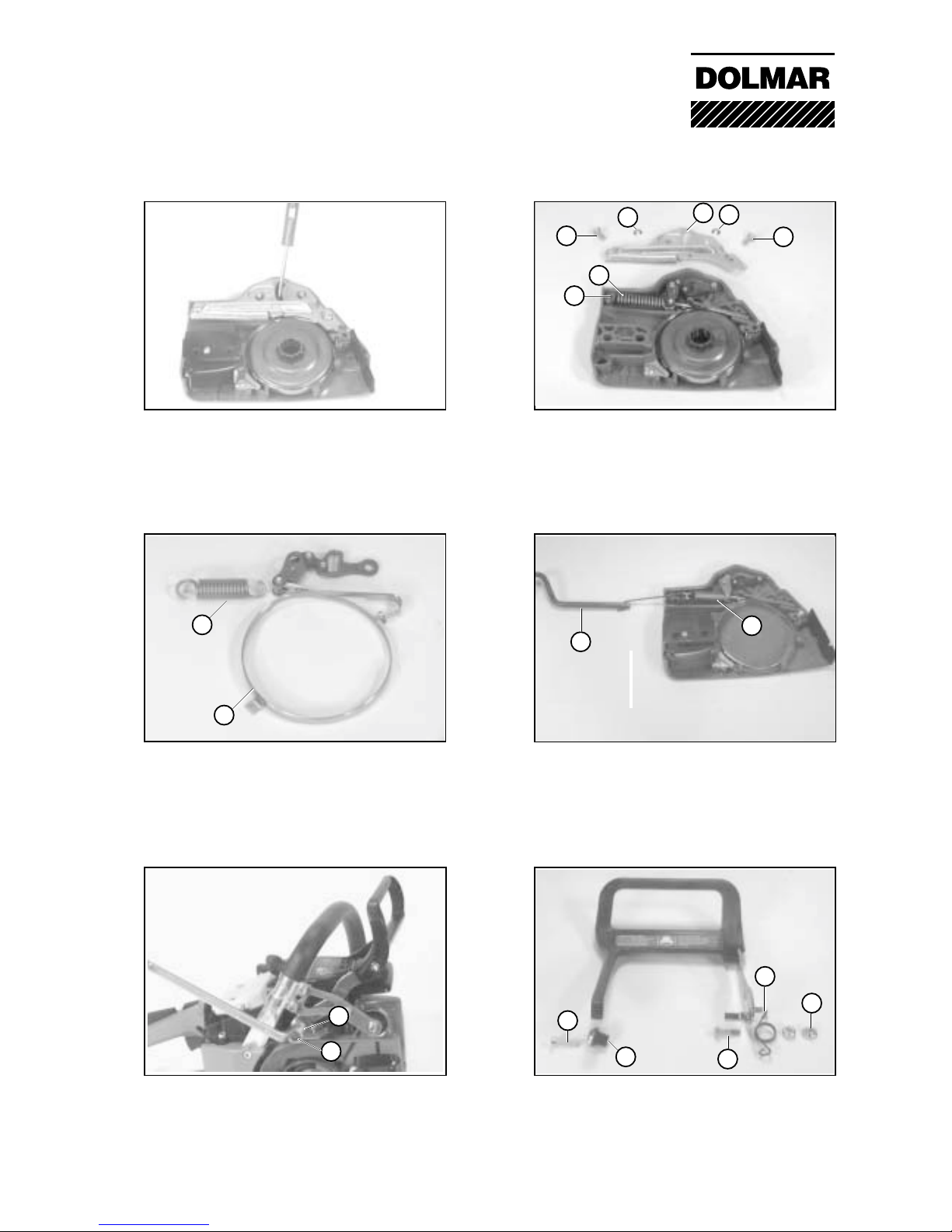
01-04 Removing the hand guard
Remove the nut (11) and push the screw (12)
in direction of the cylinder. Unscrew screw
(13) on the starter side and remove the insert
(14).
01-02 Relieving the tension spring
To remove the brake band it is necessary to
remove the cover plate (3). For this purpose
unscrew screws (4) and remove retaining
rings (5). Relieve the tension spring (6) by
levering it off the housing peg (7).
01-02 Replacing the brake band
A damaged or defective brake band (8) and a
damaged or defective tension spring must be
replaced without delay (6).
Caution: Safety components
01-04 Fitting the hand guard
When fitting the hand guard, ensure that the
compression spring (16) is installed correctly.
01-02 Pretensioning the tension spring and
the brake gate
Following the installation of the brake band,
engage the tension spring in the brake gate
(9) and using the pulling hook (10) no.
950.237.000 pass the spring over the peg (7).
01-02 Releasing the chain brake
Insert the clutch drum (1) and by levering
down the brake gate, using a screwdriver (2),
release the chain brake.
01 Chain brake
DOLMAR GmbH
6
4
2
6
3
5
6
7
8
1
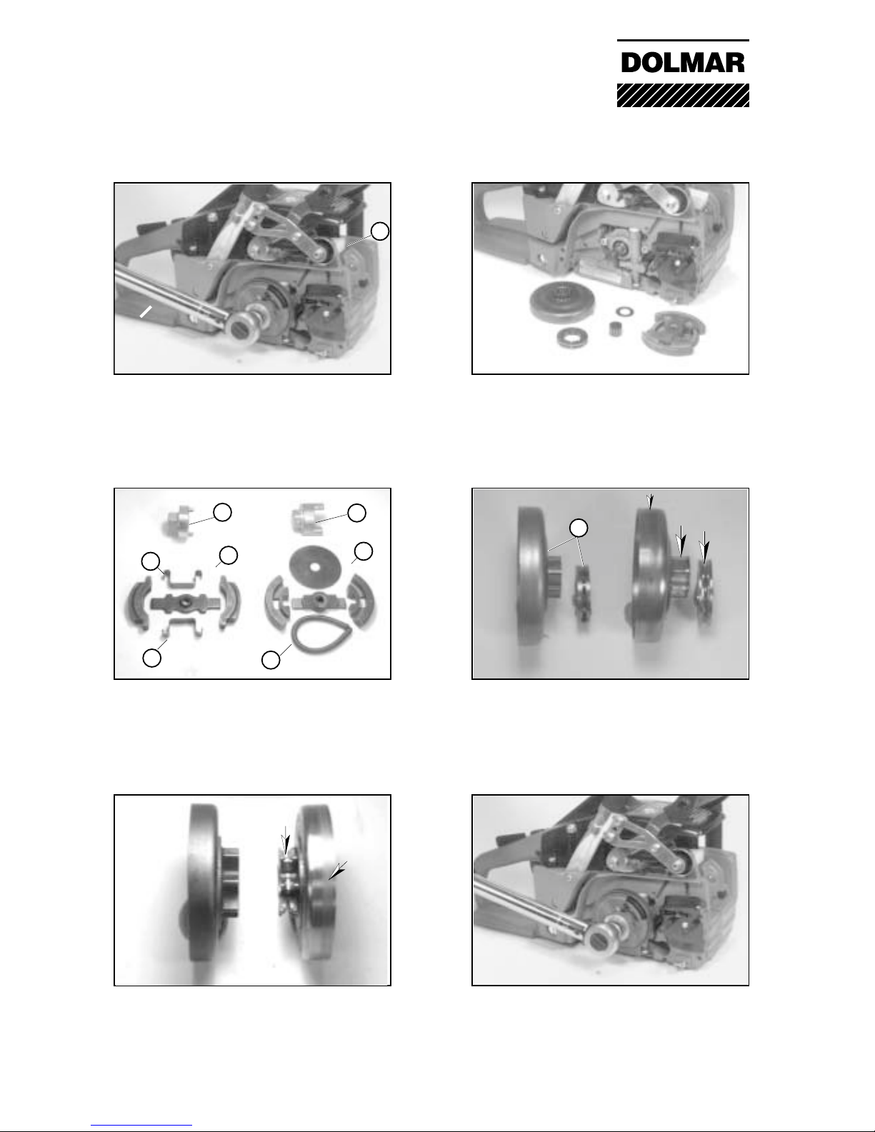
02-03 Checking the clutch drum /sprocket
of models 109 / 111
Worn sprockets or clutch drums (arrows)
must be replaced.
02-01 Removing the clutch drum
For the removal of the clutch/clutch drum it is
necessary to immobilize the cylinder unit.
For this purpose unscrew the silencer and
insert the piston stopper wedge (1) into the
exhaust duct of the cylinder.
02-01 Unscrewing the clutch
Use spanner (2), no. 944 500 680 for clutch
(3) and use spanner (4) no. 944 500 690
for clutch (5) .
Caution: Left-hand thread
02-01 Differing clutch designs
Clutch (5) for models 109, 110, 111.
Clutch (3) for model 115.
Clutch springs may be replaced as a
complete set (6) or individually (7).
02-03 Mounting the clutch drum and clutch
Prior to installation, lightly grease the clutch
drum bearing and tighten the clutch using a
torque of 35 Nm.
02-03 Checking the clutch drum /sprocket
Worn sprockets (arrows) or clutch drums must
be replaced.
Ring pinion system (8) is standard equipment
only for models 110/115. As replacement also
available for models 109/111.
02 Clutch drum
 Loading...