

Page 1

((OOrriiggiinnaall mmaannuuaall))
Page 2

Page 3
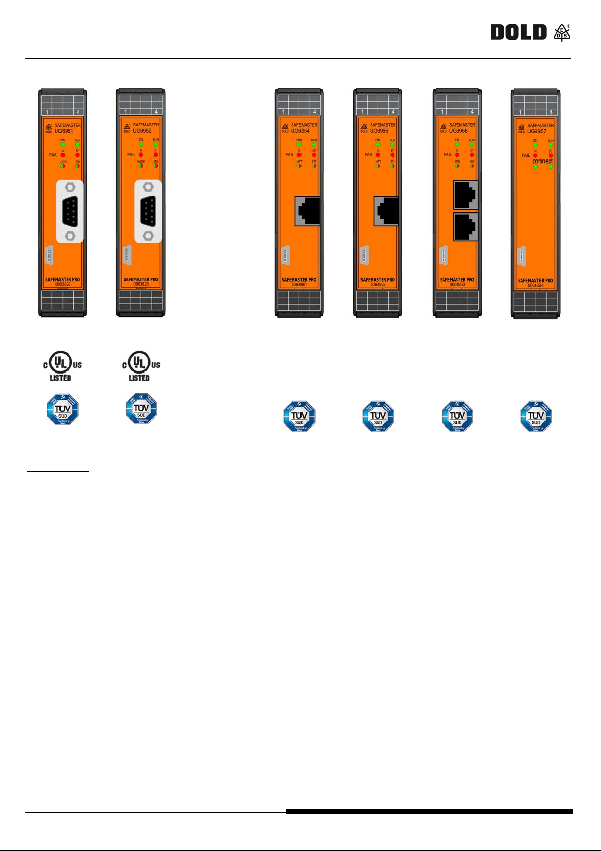
UG6951 / UG6952 / UG6954/ UG6955 / UG 6956 / UG6957
UG6951
UG6952
UG6954
UG6955
UG6956
UG6957
SAFE MAST ER PRO fieldbus mo d ules
CANopen
PROFIBUS DP
PROFINET
Ethernet/IP
EtherCAT
USB
CONTENTS
INTRODUCTION....................................................................................................................................................2
ELECTRICAL CONNECTIONS, DIMENSIONS..................................................................................................2
PROTOCOL DATA PACKAGE COMPOSITION ................................................................................................3
DIAGNOSTICS .......................................................................................................................................................5
1. Byte : "I/O inde x " ..............................................................................................................................................5
2. Byte: "Diagnostic code" ...................................................................................................................................5
Inputs ................................................................................................................................................................5
Safety outputs OSSD........................................................................................................................................5
EXAMPLES OF DIAGNOSTICS ...........................................................................................................................6
Example 1.............................................................................................................................................................6
Example 2.........................................................................................................................................................6
Example 3.........................................................................................................................................................7
Example 4.........................................................................................................................................................7
SOFTWARE BUS CONFIGURATOR"..................................................................................................................8
CONFIGURATION .................................................................................................................................................8
STATUS MONITOR .............................................................................................................................................10
Diagnostic e xa mp le ............................................................................................................................................11
VISUALISATIONS ...............................................................................................................................................12
TECHNICAL FEATURES ....................................................................................................................................15
ORDERING DATA ...............................................................................................................................................16
Declaration of conformity ......................................................................................................................................17
0265998 09.05.2017 LA 822P 1/17
Page 4
U G6951 / U G6952 / U G6954 / UG 6955 / UG6956 / U G6957
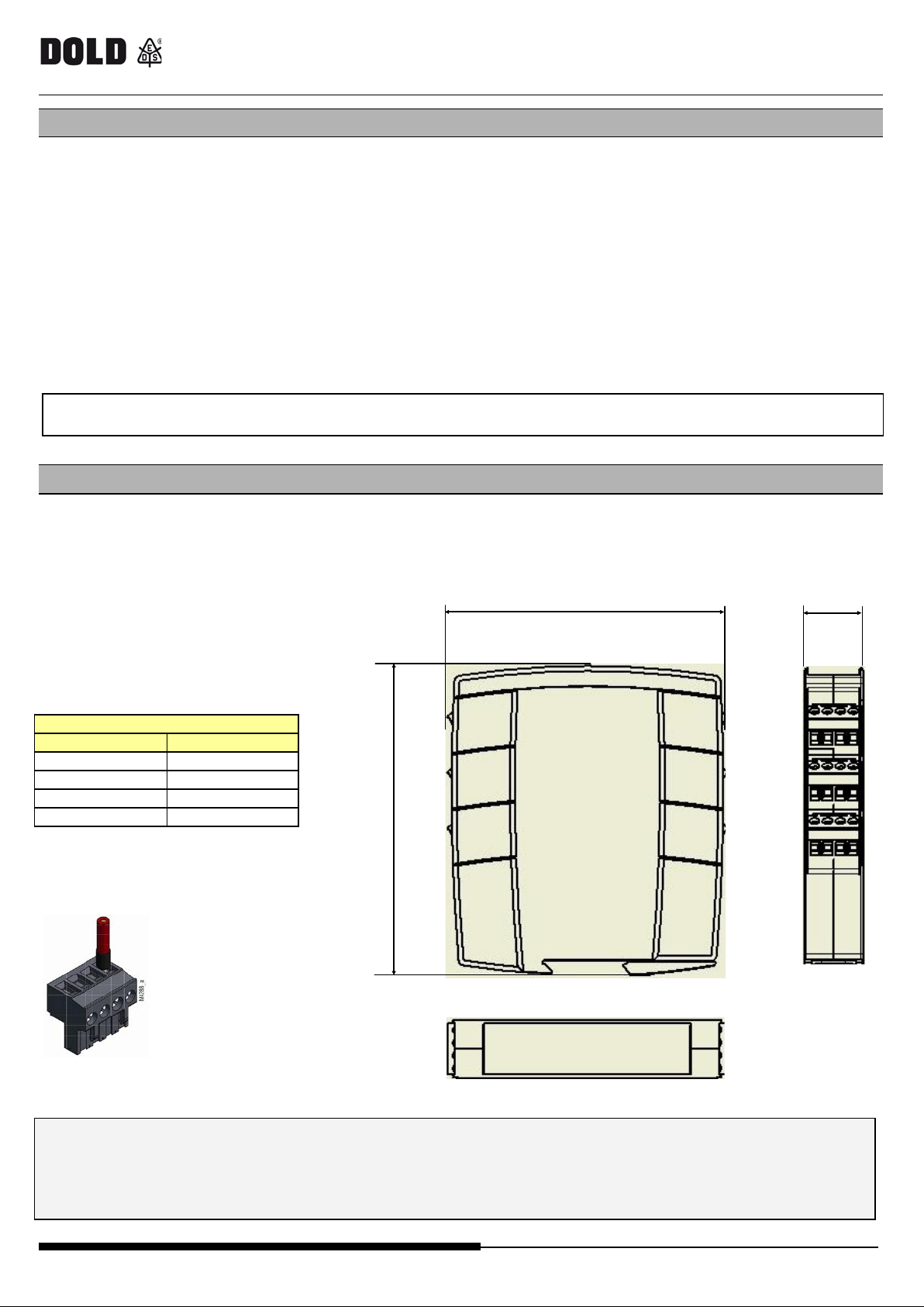
TERMINAL BLOCK
Terminal
Signal
1
+24VDC ±20%
2 3 4
GND
The s ame ground connection (0VD C) must be used for a ll syste m components.
22,5mm
109mm
122,6mm
SAFE MAST ER PRO fieldbus mo d ules
INTRODUCTION
This technical data she et describe s the oper at ion of t he fieldbus modules of the conf igurable safety system
SAFEMA STER P RO :
UG6951 Fieldbus module (CANope n)
UG6952 Fieldbus module (P ROFIBUS DP -V1)
UG6954 Fieldbus module (P ROFINET)
UG6955 Fieldbus module (Etherne t IP)
UG6956 Fieldbus module (EtherC AT)
UG6957 Fieldbus module (U SB)
The fieldbus module e xports the s ys tem s ta tus a nd the st at us a nd diagnost ic s e leme nts of all I/ Os conf igured on the
SAF EM AST ER PRO system .
These fieldbus modules have no influence on the safety functions of the configurable safety system
SAFEMASTER PRO.
ELECTRICAL CONNECTIONS, DIMENSIONS
Eac h module is provide d with four connec t ors :
- 5 way IN-RAIL-BUS connector to the system SAFEMASTER PRO
- micro US B c onnect or --> to the PC (for SW programming)
- BUS connector --> to the fieldbus
- Termin a l blo c k --> power supply
Table 1
Figure 1
Install SA F E MAST ER PRO modules in a n enclosur e with a protection class of at least IP54.
The s upply voltage to t he units must be 24Vdc ±20% (PEL V, in complia nce w ith the standar d EN 60204-1).
Do not use SAFEMA ST ER PRO to supply exter nal devic es.
2/17 0265998 09.05.2017 LA822P
Page 5

UG6951 / UG6952 / UG6954/ UG6955 / UG 6956 / UG6957
SAFE MAST ER PRO fieldbus mo d ules
PROTOCOL DATA PACKAGE COMPOSITION
The fieldbus module exports the system status and the status and diagnostics elements of all I/Os configured on the
SAF EMAS TER P RO syst em. Also import of eight inputs fr om f ieldbus is pos sible.
The system status is shown as 1 byte:
- Bit 0 indica t es whether the S AFE MAST E R P R O is online/offline
- Bit 1 indicates the presence of diagnostics elements.
Thi s byte is always present .
Each input and each output (OSSD) configured on the system is associated with two information elements: status
and diagnostics.
- Sta tus is a bina ry value , 0 or 1
Ea ch module with inputs ha s a number of bits c orr es pondin g to t he numbe r of phys ica l inputs tha t ar e
present; thus modules UG6911.10, UG6913.08, UG6916.10 are associ at ed wit h 1 byt e, modules UG6913.12,
UG6913. 1 6 w i t h 2 byt es.
The input byte loc at io n va ries ac c ording to the type of modules tha t a re insta lle d , in the followi ng orde r :
UG6911.10, UG6916.10, UG6913.16, UG6913.08, UG6913.12.
If se ver a l module s of the sa me t ype a re insta lled the orde r follows the node numbe r.
All safety out p ut s ar e s um maris ed i n 1 or 2 byt es (dep en di ng on sys t em conf i g urati on ).
- Diagnostic s is a code indicating t he condition of the I /O , w hic h c an be OK or indicate a problem on t he I /O .
Diagnostics elements are in the form of 2 byte s w hich indica te the index of the I/O with the problem a nd
the value of the dia gnost ic s element.
If there is more than one diagnostics element, the relative values alternate every 500 ms.
Eac h set of information:
- input status,
- input diagnostics,
- fieldbus inputs sta tus ,
- fieldbus pr obes s tat us,
- sa fety output status,
- sa fe ty out put dia gnostic s
can be enabled/disabled in order to control the information and thus the number of output bytes exported to the
fieldbus.
One input byte with the whishe d stat e of fieldbus inputs must always be pr esent, also if no fieldbus inputs a re used in the
electric schema.
For t he f ie ldbuses in which t he mapping position is mandatory (i. e. PR OFI BU S ) the input byte mus t be mapped be fore the
output byt es .
For t he fieldbuses based on CANOpen the data can be accessed only via PDO. SDO access is not supported.
0265998 09.05.2017 LA 822P 3/17
Page 6
U G6951 / U G6952 / U G6954 / UG 6955 / UG6956 / U G6957
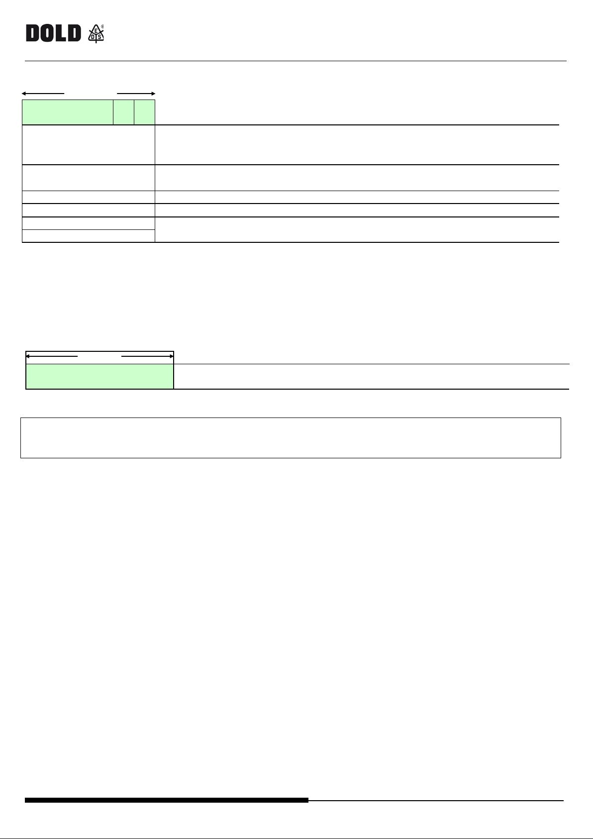
(1 byte)
SY STEM STATUS
(always present )
B0=1: SAFEMASTER PRO onli ne
B1=1: Diagnostics present
INPUTS
Ma ximum: 16 bytes)
recognised state of Fieldbus inputs
Fieldbus probes (2 bytes)
OUTPUTS OSSD (max. 2 bytes)
Index of I/O
DIAGNOSTICS
(2 bytes)
Diagnos tic c ode
(1 B yt e)
whished state of fieldbus inputs
(1 B yt e)
This byte must always be present, also if no
fieldbus inputs a re used in the electric schema.
SAFE MAST ER PRO fieldbus mo d ules
This table show s the pla ceme nt of t he Fie ldbus out put byte s ( F ieldbus module t o F ie ldbus PLC)
B1 B0
(Minimum: 1byte
(1 byte)
see Table 2, 3
One input byte ( Fie ldbus PLC to Fieldbus module) must always be de fined f or the whishe d stat es of fieldbus inputs.
If the SAFEMASTER PRO system includes a fieldbus module, the SAFEMASTER PRO Designer report will
include a table with the I / O index for all the inputs , fieldbus probe s and s afety outputs used in t he elect ric
circuit.
4/17 0265998 09.05.2017 LA822P
Page 7
UG6951 / UG6952 / UG6954/ UG6955 / UG 6956 / UG6957
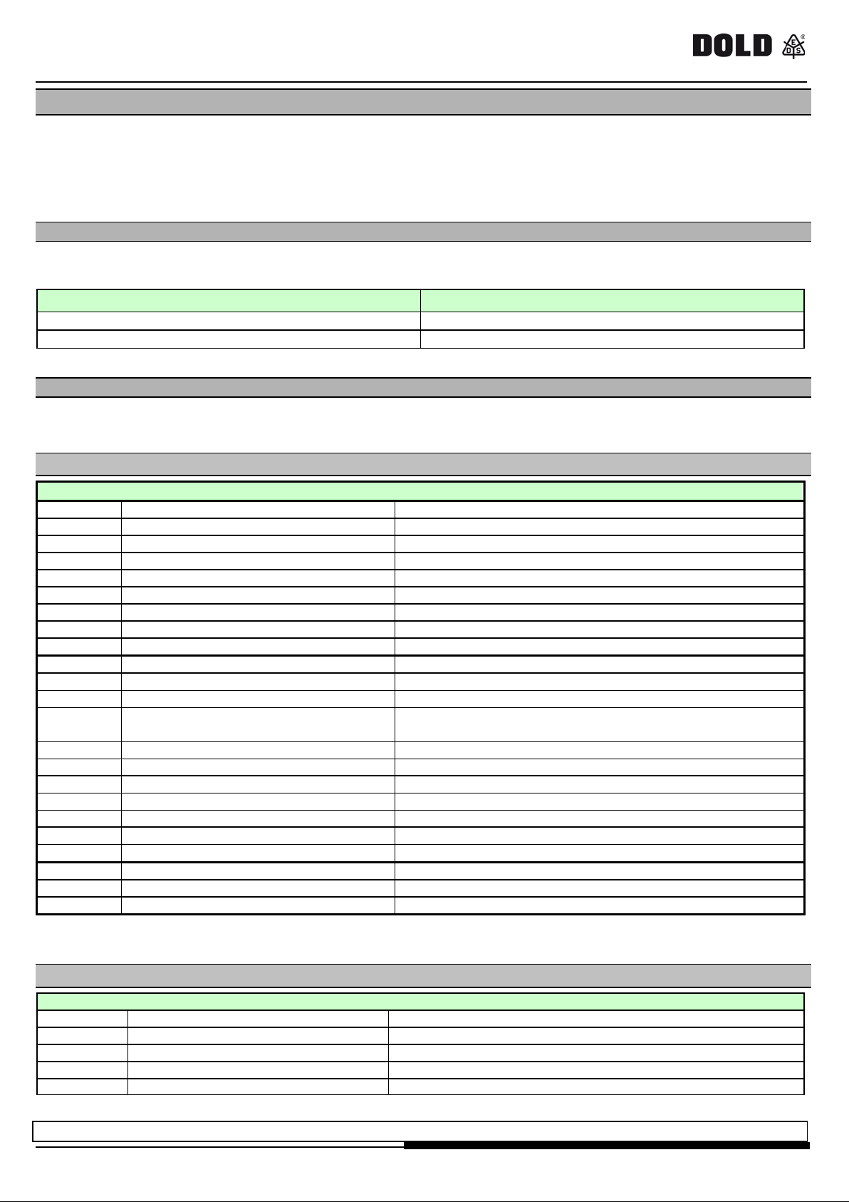
TY PE OF SIGNAL
I/O INDEX
Input
1-128
Output
192-255
In put di ag n ostics
128 (0x80)
Input diagnostics OK
1 No t in in itia l p o s itio n
Both s witches have to go to rest condition
2
Concu rrent failed
Both switches have to change state s imultaneously
3
Concurrent failed hand1
Wrong connection on one side of a two-hands s witch
4
Concurrent failed hand2
Wrong connection on one side of a two-hands s witch
7
invalid switch pos ition
The selector can't have more than one input s et
8
Switch not connected
The s elect or can't have any input s et
10 (0x0A)
OUT_TEST error
OUT_TEST fai lure on this input
11 (0x0B)
Se c ond i nput de fecti ve
Redundancy check failed on input
12
O UT_ T EST diagnostics OK
13
O utput c onne c t e d to ot he r inputs
Test output not connected to the right input
14
O utput OK but input connected t o 24VDC
Stuck input
Shor t cir cui t betwee n photocel l test and
photocell input
16
N o r esponse fr om photocel l
The test s ignal on the photocell emitter is not seen on the receiver
17
Short ci rcuit between phot oc e lls
The test s ignal is present on two different photcells
18
MAT discon nected
Wrong mat c onne c t ion
19
O utput inconsistent w ith f e e dba c k
The test s ignal on input is present on more than one OUT_TEST
20
Connection incorrect
The test signal is pre sent on more than one input
21
Output stuck
The test signal on the input is not pre sent on t he OUT_TEST
22 (0x16)
Second OUT_TEST KO
Redundanc y c he c k fa iled on OUT_TEST
133 (0x85)*)
TWO-HAN D concurrent fai l ed
Two-hands switch has to change state simultaneously
134 (0x86)*)
Not started
Start test failed
137 (0x89)*)
W ait in g fo r re st a rt
The input has manual reset and has not been res tarted
OSSD Diagnostics
0
OSSD DIAGNOSTICS OK
1 ENABLE MISSING
2 WAITING FOR RESTART OSSD
3 FEEDBACK K1/K2 M ISSING
4 WAITING FOR OTHER MICRO
Redundancy check failed on OSSD
SAFE MAST ER PRO fieldbus mo d ules
DIAGNOSTICS
Each input and safety output i s associated with a relative diagnostic code.
When the I/O is connected correctly the dia gnostic c ode is OK and is not exported to the fieldbus;
if the re is a proble m on the I/O, the syst em exports 2 byt es to the fieldbus with:
- the index of t he I/O in que stion
- the related diagnostic code
1. Byte: "I/O index"
This fie ld indicates the number used to identify the I /O with a diagnost ic c ode other than OK .
Possible values f or this field are show n in Table 2.
Table 2
2. Byte: "Diagnostic code"
The "Diagnostic code" field indicates the diagnost ics for the I/O. Possible values for this field are shown in the
following tables.
Inputs
15
Photoc el l response ti m e too low
)
*
The diagnos tic 133, 134 and 137 do not provide visua l err or messa ge on the LED from SAFEMA STE R P RO
Table 3
Safety outputs OSSD
Table 4
If there are more than one diagnostic codes, the information changes every 500ms.
0265998 09.05.2017 LA 822P 5/17
Page 8
U G6951 / U G6952 / U G6954 / UG 6955 / UG6956 / U G6957
Ind e x I /O 1
Ind e x I /O 2
SAFE MAST ER PRO fieldbus mo d ules
EXAMPLES OF DIA GNOSTICS
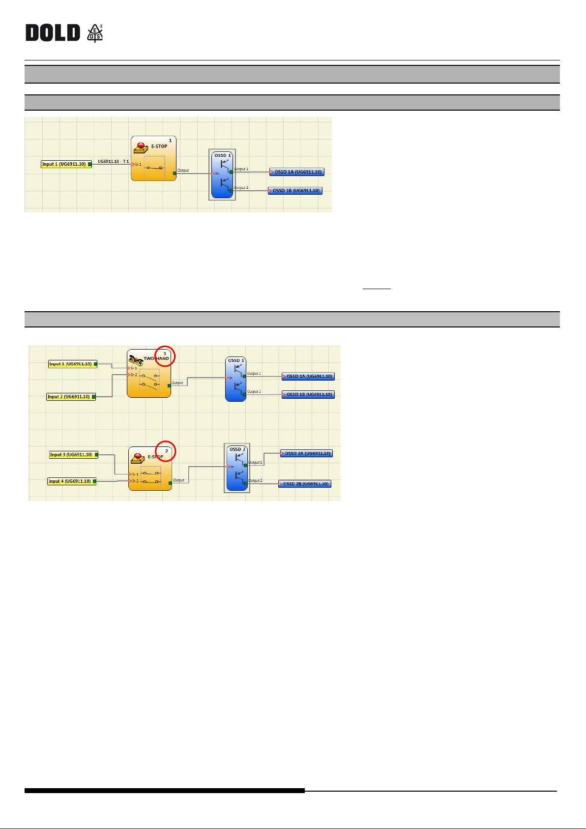
Example 1
Figure 2
In t he e xamp le s how n in Figure 2, Input 1 (connected to module UG6911.10) is tested with the UG6911.10-T1
t e s t s ig nal.
During wiring, the 24Vdc is connected to input 1 instead of the UG6911.10-T1 te st s ig na l.
- The I /O ind ex and D iagno st ic c od e sho w the follow ing va lues: 1 - 10 to indicate the diagnostics on
Example 2
input 1 of module UG6911.10 (OUT_TEST error)
Figure 3
In this example, the I/O index corresponds to the logical block and not to the physical termina l on module
UG6911.10.
In Figure 3 for e xamp le, the two -hand element c onne cte d to t he Inp ut 1 and Inp ut 2 physic al t ermina ls
corresponds to I/O index No. 1 and the emergency stop connected to the Input 3 and Input 4 terminals
corres pon ds to I/O i n dex No. 2.
6/17 0265998 09.05.2017 LA822P
Page 9
UG6951 / UG6952 / UG6954/ UG6955 / UG 6956 / UG6957
SAFE MAST ER PRO fieldbus mo d ules
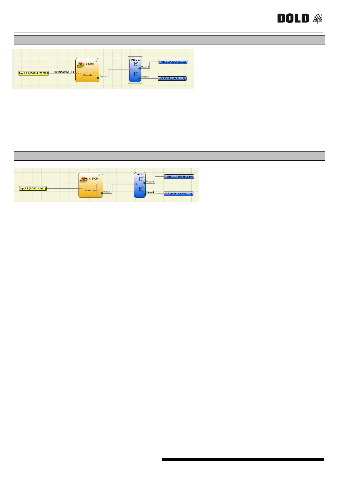
Example 3
Figure 4
The example in Figure 4 is similar to example 1, except in this case Input1 is connected to module UG6913.16
and is tested with the UG6913.16-T 1 te s t signa l.
During wiring, the 24Vdc is connected to input 1 instead of the UG6913.16-T 1 t e st s ig na l.
- The I /O ind ex and D iagno st ic c od e sho w the follow ing va lues: 1 - 10 (OUT_TEST error) to indicate the
d iagno s t ic s o n input 1 of module UG6913.16
Example 4
Figure 5
In t he e xamp le s how n in Figure 5 the manual reset functio n is enabled o n OS SD 1.
The E-Stop-button connected to input 1 is released without sending a reset command.
- The I/O index and Diagno s t ic s c o d e sho w the fo llow i n g va lue s : 192 - 2
- to indicate the OSSD 1A/1B (Table 2: 192 = first output).
- to indicate the diagnostic code (Table 4: 2 = Waiting for OSSD to restart).
0265998 09.05.2017 LA 822P 7/17
Page 10
U G6951 / U G6952 / U G6954 / UG 6955 / UG6956 / U G6957
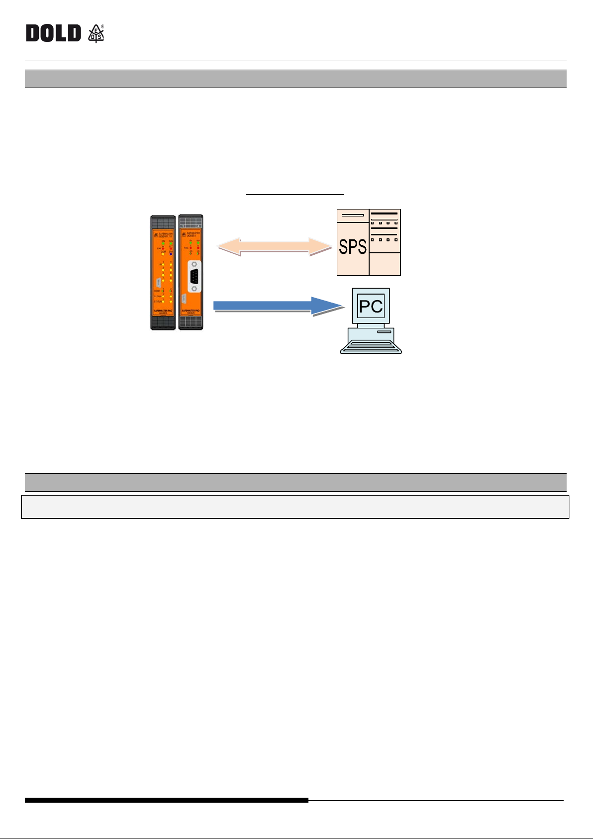
UG695x <-> SPS
(bi-directional)
UG695x <-> SPS
(only m onitoring)
UG6911 UG695x
SAFE MAST ER PRO fieldbus mo d ules
SOFTWARE BUS CONFIGURATOR"
The fieldbus module is configure d via the micro U S B interface on the f ront panel and using the "BUS
CONFIGURATOR" software on the SAFEMASTER PRO Designer CD-ROM.
Th i s soft ware al lows configuring a ll fieldbus modules. It allows a lso the bi-directional communication of the
SAF EM AST ER PRO system with a PC (us ing fieldbus module UG6957 for USB ) or the display of t he data, that is
transferred on the INRAIL-Bus of the SAFEMASTER PRO System (via the USB Port of the fieldbus modules ). The
following pict ure demonstr at es the poss ible connec tions:
It is important to point out the diff er ence in behaviour oft the B US CONFI GURATOR when communic at ing with t he
modules U G6951 t o UG6956 a nd the module UG6957 ( USB ):
• Modu l e UG 69 51 t o U G 59 56: The software only all ows the display of data that is transferred on the INRAIL Bus.
• Modu l e UG 69 57 : The software allows the bi-d irection al data t ran s fer . In t h is case t h e o p er ato r can set t h e state o f
the inputs “Fieldbus Input ” direc tly f rom the computer.
Conne ction Example
via fieldbus
v ia US B
Figure 6
CONFIGURATION
The module must be configure d with t he out puts disable d (outputs OFF).
Following parameters to exchange can be set:
- Input / output s ta te s
- diagnostic data
- bytes "fieldbus input" and "fieldbus output" used in the electric schema
- module a ddress in the fieldbus ne twork
- baudra te, in modules w her e this is e nvisa ged
The addr es s ra nge de pe nds on the type of f ieldbus tha t is inst alle d.
Module conf iguration c an be quer ied a t any time during module ope ration.
To configure t he fieldbus module, procee d as f ollows:
1. connect the module via the IN-RAIL-BU S to the SAF EMAST ER PRO s yst em;
2. conne ct the SAFEMASTER PRO syste m to t he 24VD C +20% voltage powe r s upply via the ter minal s trip;
ATTENTION: the mas t er unit U G6911. 10 must be without er ror state.
3. conne ct the USB ca ble to the P C a nd to the fieldbus module;
4. star t up t he "B US CONFIGURATOR" software.
8/17 0265998 09.05.2017 LA822P
Page 11
UG6951 / UG6952 / UG6954/ UG6955 / UG 6956 / UG6957
ADDRESS
BAUDRATE
UG6951 (CANopen)
127
AUTO
UG6952 (PROFIBUS DP-V1)
126
N/A
UG6954 (Profinet)
auto selection
N/A
UG6955 (Ethernet IP)
0.0.0.0
AUTO
UG6956 (EtherCAT)
0
N/A
Data sets
Input status, Fieldbus input status, probe status, output status
SAFE MAST ER PRO fieldbus mo d ules
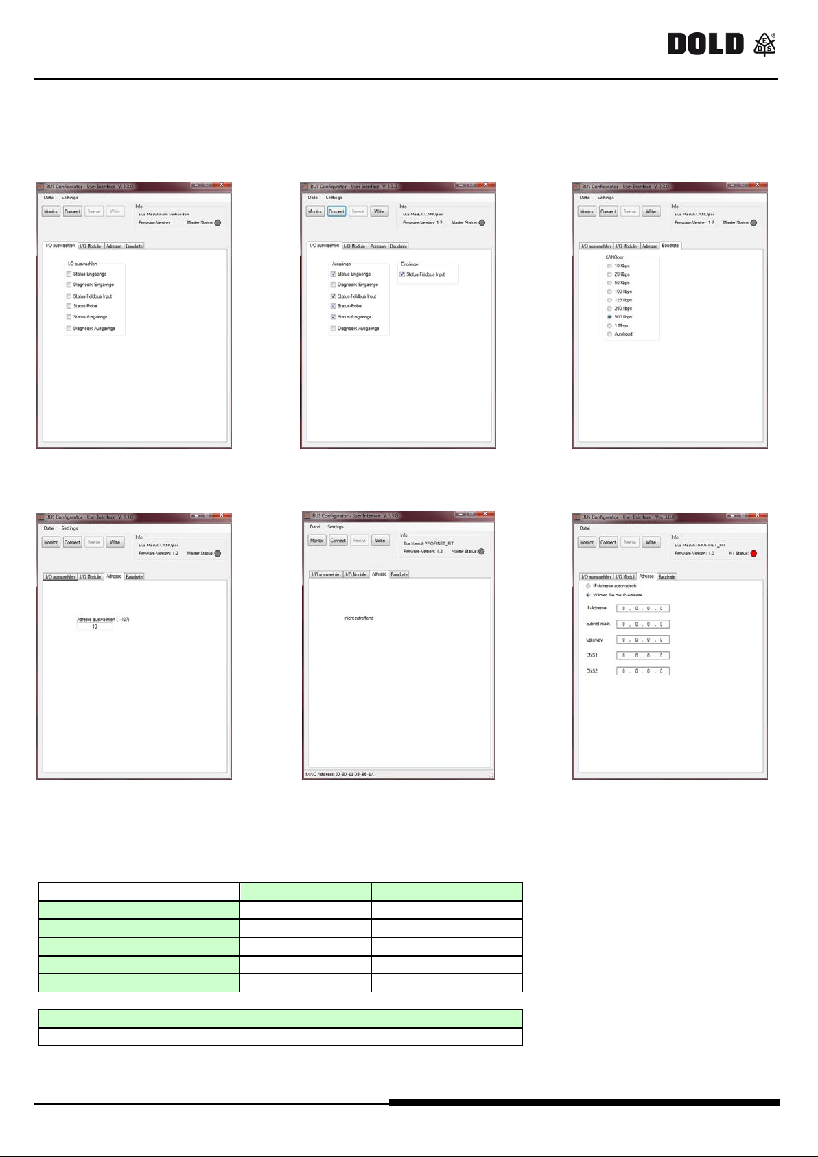
The conf igurat ion w indow is displaye d (Figure 7). The program recognizes that a bus module is conne ct ed;
By clic k on t he "Connect" button the fieldbus type and its firmwar e ver sion is displa yed (Figure 8) .
The configurable parameters can be adjusted by selecting the different tabs (Figures 8 to 11):
Sta rt window diagnostic sel ection Baudrate
(not a ll m odule types)
Figure 7 Figure 8 Figure 9
Address selecti on
(UG6951, UG6952, UG6953, UG6956) (UG6954, automati c a dd ress selecti on) (UG6955)
Figure 10 Figure 11 Figure 12
Afte r s etting the parameters, c lick on "Write" to send the new configuration to the module.
Table 5 - Default values
0265998 09.05.2017 LA 822P 9/17
Page 12
U G6951 / U G6952 / U G6954 / UG 6955 / UG6956 / U G6957
SAFE MAST ER PRO fieldbus mo d ules
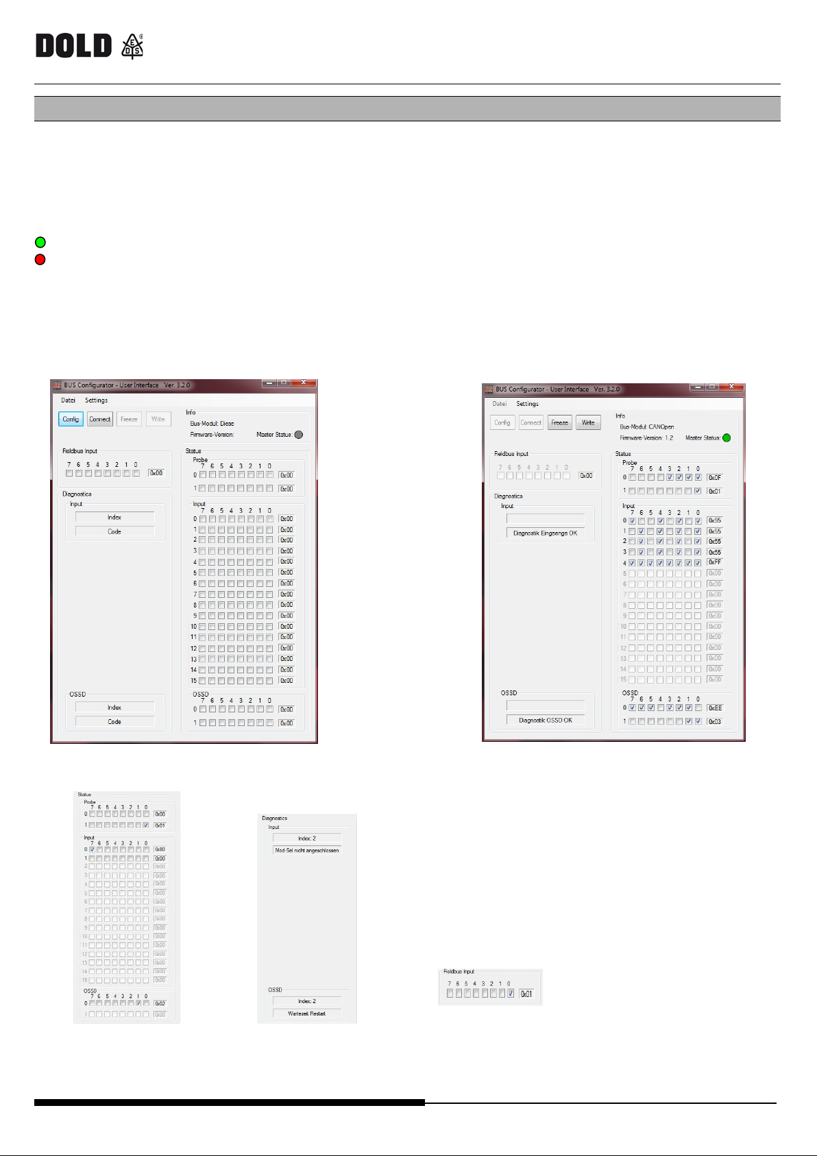
STATUS MONITOR
After transmission of the para meters it is possible to change to t he stat us monitoring window t o watch t he stat us of t he
sys te m by pre ss ing the button „MONITOR (figure 12).
By pr ess ing the but t on "Connect" the cyclic reading of the diagnosis dat a is star te d.
As soo n as the da ta ar rives in the Bus module, t he dyna mic sta tus display is s hown ( figure 13).
The status of the control unit UG6911.10 (Master Status) is displayed:
green: UG6911.10 active (RUN);
red: UG6911.10 not active (e. g. in communicat ion with "SAFEMASTER PRO Des igne r ").
- Window ar ea figure 14 shows t he stat us of t he in- and output s.
- Window ar ea f igure 15 s hows the diagnosis in the c a se of fa ilure s (c yc lic display, if more tha n one incor re c t
eve nt ha ppe ns) .
- Window ar ea f igure 16 s hows the inputs „Fie ldbus Input s", the sta tus of which c an be cha nge d by the use r on
PC screen with the B us Configura t or using module UG6917 for U S B or which is sent via fieldbus.
Figure 13
fieldbus Input
state of i npu ts / outputs (adjus table only
i npu ts / outputs diagnostics with UG6957)
Figure 15 Figure 16 Figure 17
: Monitor-window Figure 14: Diagno stic data
10/17 0265998 09.05.2017 LA822P
Page 13

UG6951 / UG6952 / UG6954/ UG6955 / UG 6956 / UG6957
- The input 1 ENABLE is connected to Input 8 (terminal
1 2 3 5 3 2 4 4 1
3
1
2
1
2 3 3
4
1
4 4 4
5
5
CANOp en
Master Status:
SAFE MAST ER PRO fieldbus mo d ules
Diagnostic example
Figure 18: P rojec t example on SAFEMASTER PRO DESIGNER
24) oft he control unit UG6911.10 and its status (0 or
1 ) is shown in the field "S ta t us I nput " at bit 7 of the
bytes 0 .
- The input 2 MOD-SEL is connect e d to i nput s 1 a nd 2
(terminals 17 and 18) of the extension module
UG6916.10. The diagnosis indicates failure (dotted
ora ng e line). The status is indicated in the section
"Sta tus Input" and by the bi t pair 0 and 1 of the byte 1.
The diagnosis is displayed in the section "Diagnostics
Input" with index 2 and the corresponding description.
- The Probe at Bit 6 and Bit 8 are displayed in green and
the corresponding bits are indicated in the section
“Status Probe". Bi t 8 is displayed as bit 0 of the
second byte.
- O SS D 1 is ON and connecte d to the second output pa ir
of the control unit UG6911.10 (terminals 9 and 10). Its
status is displaye d in section "Sta tu s O SSD " at bit 1 of
byte 0.
- OSSD 2 is OFF and connected to the second output
pair (termina ls 5 and 6 ) of the extension module
UG6916.10. The diagnosis shows that the system is
waiting for a restart. Its status is displayed in section
"Status OSSD" at bit 3 of bytes 0. The diagnosis is
displayed in section "Diagnostics OSSD" with Index 2
and the corresponding description.
- In section "Fieldbus Input" Bit 0 is selected and as a
result the "Fieldbus Input" Bit 0 in the configuration
plan appears in green color.
Figure 19
Attention: The function "Setting of Fieldbus Input" can only be used w ith the Bus-Configurator Software via a field bus
module UG6957 (USB). With the modules (UG6951 to UG6956) for other field bus systems the change of these inputs can only
be made via the bus.
0265998 09.05.2017 LA 822P 11/17
Page 14
U G6951 / U G6952 / U G6954 / UG 6955 / UG6956 / U G6957
UG6951
CANopen
UG6952
PROFIBUS DP
UG6954
PROFINET
UG6955
Ethernet/IP
UG6956
EtherCAT
UG6957
USB
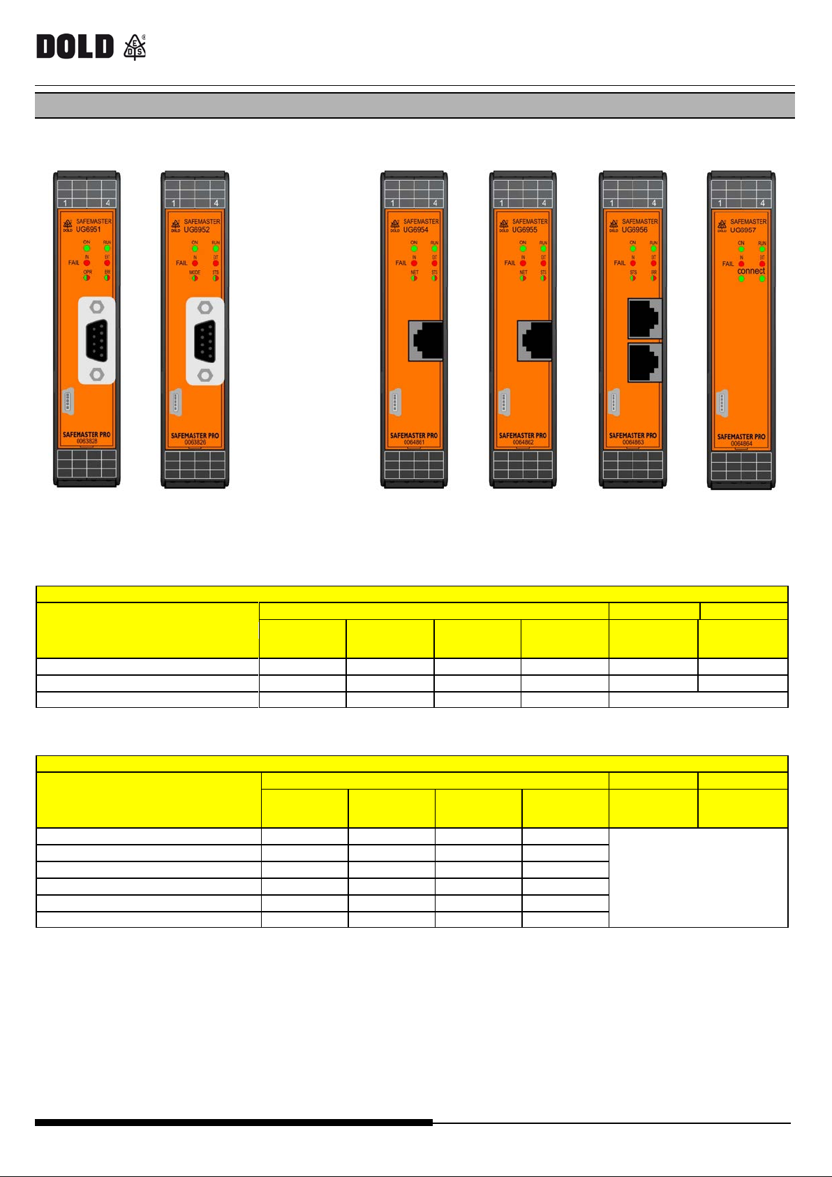
NORMAL OPERATION
upper 4 LEDs
LED 1
LED 2
ON
RUN
IN FA IL
EXT FAIL
Startup - Initial test
ON
ON
ON
ON
ON
ON
Waiting for confi gu rati on
ON
flashing
OFF
OFF
OFF
OFF
Configuration received
ON
ON
OFF
OFF
see the module tables
FAULT STATE
upper 4 LEDs
LED 1
LED 2
ON
RUN
IN FA IL
EXT FAIL
Internal fault microcontroller
ON
OFF
2 flashes*
OFF
Internal failure
ON
OFF
3 flashes*
OFF
Configuration Error
ON
OFF
5 flashes*
OFF
BUS c ommuni c ati on Err or
ON
OFF
5 flash es *
OFF
BUS communication interruption
ON
OFF
ON
OFF
Identical modul e detected
ON
OFF
5 flashes*
5 flashes
LED 1, 2
SAFE MAST ER PRO fieldbus mo d ules
VISUALISATIONS
Description
GREEN
GREEN
RED
RED
RED/GREEN RED/GREEN
Table 6
Description
GREEN
GREEN
RED
RED
Table 7
* The LED frequency of flashing is: ON for 300ms and OFF for 400ms , with an interval between two sequences of 1s.
RED/GREEN RED/GREEN
see the module tables
12/17 0265998 09.05.2017 LA822P
Page 15
UG6951 / UG6952 / UG6954/ UG6955 / UG 6956 / UG6957
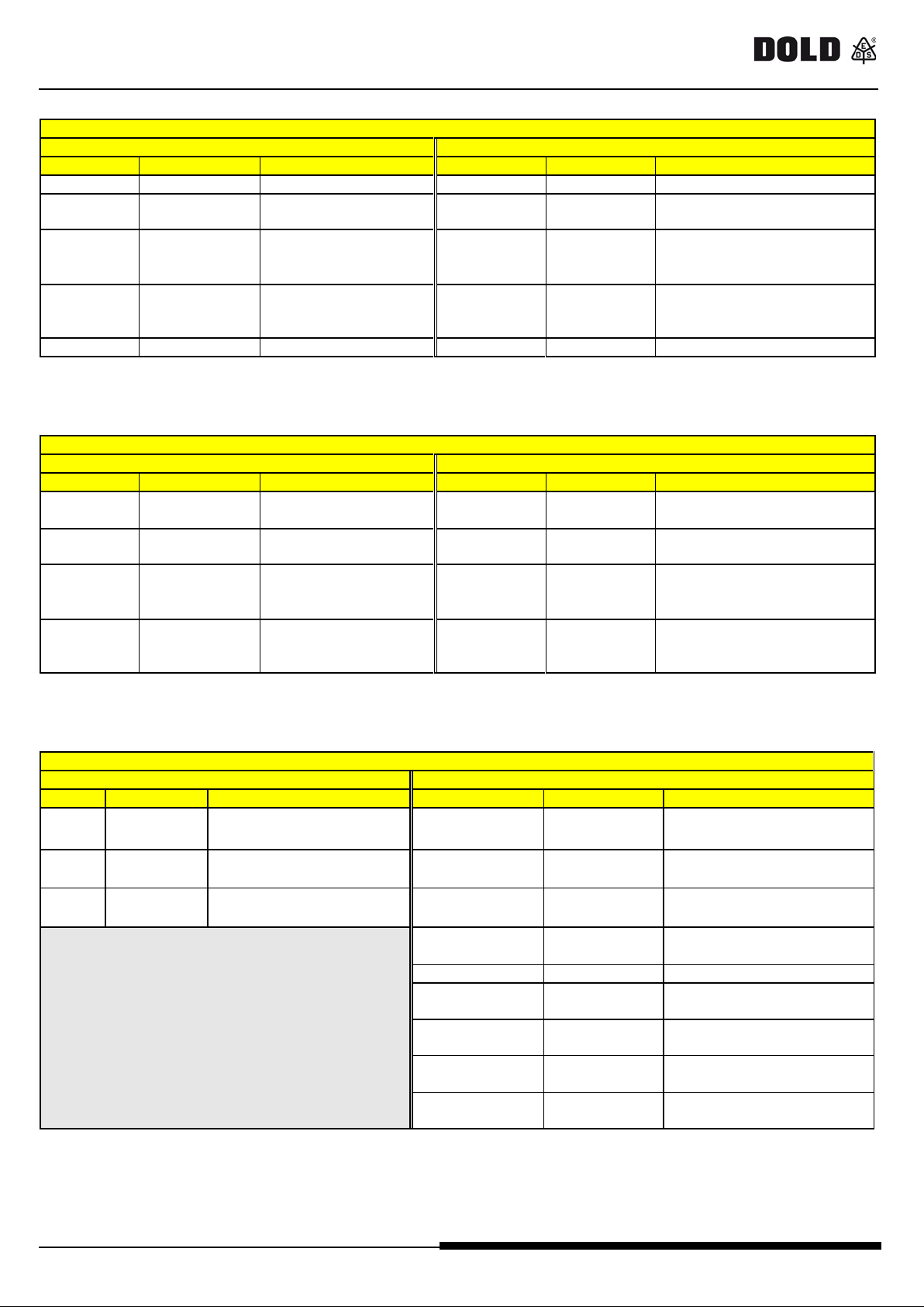
MODULE UG6951 (CANopen)
LED 1 : OPR
L ED 2: ER R
STATUS
INDICATION
DESCRIPTION
STATUS
INDICATION
DESCRIPTION
GREEN
OPERATIONAL
OPERATIONA L status
OFF
-
Normal operation
GREEN
flashing slow
PRE-
OPERATIONAL
PRE-OPERATIONAL
status
RED flashing
(1 fl ash)
A bus error cou nter has reached
the warning level
GREEN
(1 fl ash)
Detected Node Guar di ng (NMT
(Consumer)
RED
EXCEPTION
EXCEPT ION status
RED
Missing BUS
BUS not working
MODULE UG6952 (PROFIBU S DP V1)
LED 1: MODE
LE D 2: STS
STATUS
INDICATION
DESCRIPTION
STATUS
INDICATION
DESCRIPTION
UG6952 not
initialized
GREEN
flashing
g
Initialized with
active
bit
PROFIBUS
error
configuration data
wrong
MODULE UG6954 (PROFINET)
LED 1 : NET
LE D 2: STS
STATE
INDICATES
DESCRIPTION
STATE
INDICATES
DESCRIPTION
no connection
connection established
RUN s tate
Normal
operation
green
flashing
STOP state
gr e en fl as hi ng
(1 fl ash)
gr e en fl as hi ng
(2 fl ash)
Used to identif y the ne two rk
node
red
Exception
Module in EXCEPTION s tate
re d fl ashi ng
(1 fl ash)
Configuration
error
red flashing
(2 fl ashes )
IP ad d re ss e rro r
re d fl ashi ng
Station name
re d fl ashi ng
(4 fl ashes )
SAFE MAST ER PRO fieldbus mo d ules
Warning level
flashing
GREEN
blin kin g fast
STOPPED STOPPED status
Autobaud Baudrate detection
RED flashing
RED flashing
(2 flashes)
Table 8
GREEN On-line data exchange OFF
On-line CLEAR GREEN Initialized End o f initia li za t io n NW_INIT
RED flashing
(1 fl ash)
RED flas hi ng
(2 flashes)
Parameterization
error
configuration
ref.
IEC 61158-6
MASTER or UG6952
GREEN fl as hin
Table 9
fast
RED Exception error EXCEPTION STATUS
LSS LSS service operative
Event Control
diagnostic
master or slave ) or Heartbeat
STATUS SETUP or NW_INIT
EXTENDED DIAGNOSTIC
set
OFF Offline
green Online (Run)
Online (stop)
no power
connection established
OFF n o t initia l ised
green
Diagnostic event
Blink
(3 fl ashes )
error
Int e rn a l erro r
Identification error
IP address not configured
Sta t ion name not c onfi gur e d
Table 10
0265998 09.05.2017 LA 822P 13/17
Page 16
U G6951 / U G6952 / U G6954 / UG 6955 / UG6956 / U G6957
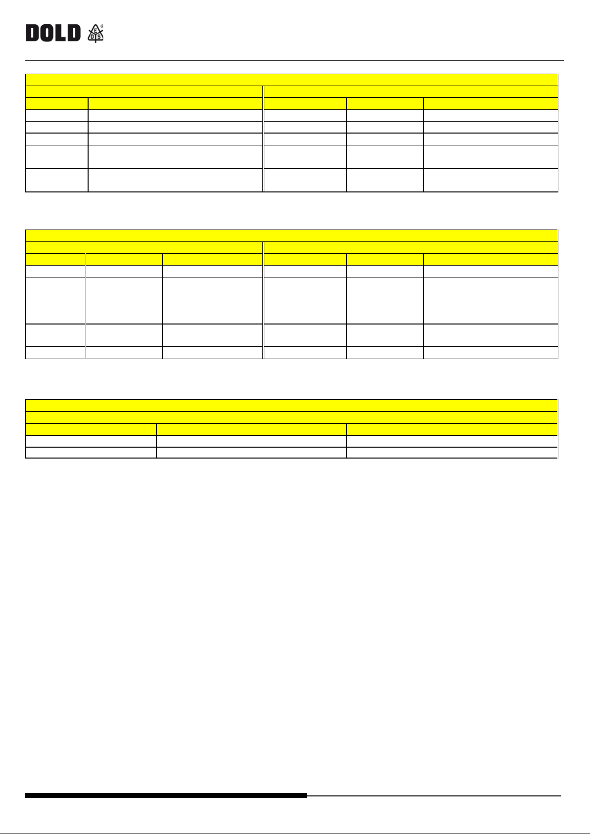
UG6955 (Eth e rn e t IP)
L ED 1: NET
LED 2: S TS
STATE
INDICATES/DESCRIPTION
STATE
INDICATES
DESCRIPTION
OFF
no power or no IP a ddress
OFF
no power
green
on-line, connected
green
RUN s tat e
green flashing
on-line, not connected
green flashing
not configured
dupli cate I P addr ess
one or more non-recoverable
err ors dete cted
connection timeout
one or m ore recoverable
err ors dete cted
UG6956 (EtherCAT)
LED 1: S TS
L ED 2: ERR
STATE
INDICATES
DESCRIPTION
STATE
INDICATES
DESCRIPTION
OFF
INIT
INIT or no pow er
OFF
No e rro r
No er ror or no power
OPERATIONAL state
Configuration not
valid
Status cha nge reque s ted by
master not pos sible
green flashing
PRE-
OPERATIONAL
PRE-OPERATIONA L
state
re d fl ashi ng
(2 fl ashes )
Watchdog
timeout
Synch m anager wat chdog
timeout
green flashing
(1 fl ash)
SAFE-
OPERATIONAL
SAFEOPERA TIONAL
state
module in EXCEPT ION state
Red
(Fatal Event)
System locked
-
-
-
UG6957 (USB)
2 LEDs: conn ect
STATE
INDICATES
DESCRIPTION
ON
USB connection
Module connected on PC
OFF
no USB connection
Module not connected
SAFE MAST ER PRO fieldbus mo d ules
red
re d fl ashi ng
green OPERATIONA L
red fat a l erro r
re d fl ashi ng error
Table 11
re d fl ashi ng
red Controller fault
Table 12
Table 13
14/17 0265998 09.05.2017 LA822P
Page 17
UG6951 / UG6952 / UG6954/ UG6955 / UG 6956 / UG6957
24VDC ± 20% / Remote Class 2 Source
or limited voltage limited current
Nominal consumption
max. 3 W
Connection to Safemas ter Pro
via 5-pole IN-RAIL-BUS
USB 2.0 (Hi Speed) - front plug
Max cable length: 3m
Connection to fieldbus
via 2. front c onnec t or
1 x 0,25 ... 2,5 mm2 solid or
stranded ferruled (isolated)
Insulation of wires or sleeve length:
7 mm
W ire fxing:
captive slotted screw M3
Tightening torque:
0,5 ... 0,6 Nm
Operating temperature
-10 ÷ 55°C
Storage temperature
-20 ÷ 85°C
Relative hum idity
10% ÷ 95%
Electronic housing
DIN-R ail mounting
Enclosure m aterial
Polyamide
Enclosure protection class
IP 4 0
Term inal blocks protection class
IP 2 0
Fastening
Quick fixing to rail according to EN 60715
Dimensions (h x l x d)
109 x 22,5 x 120,3
Weight
150g
the safety functions were not evaluated by UL.
Standard UL 508, “general us e applications ”
For use in Pollution degree 2,
overvoltage category I I environment only
Max surrounding air temperature
55°C
60°C / 75°C copper conductors only
AWG 30÷12 (solid/stranded) Torque 5-7 lb-in
SAFE MAST ER PRO fieldbus mo d ules
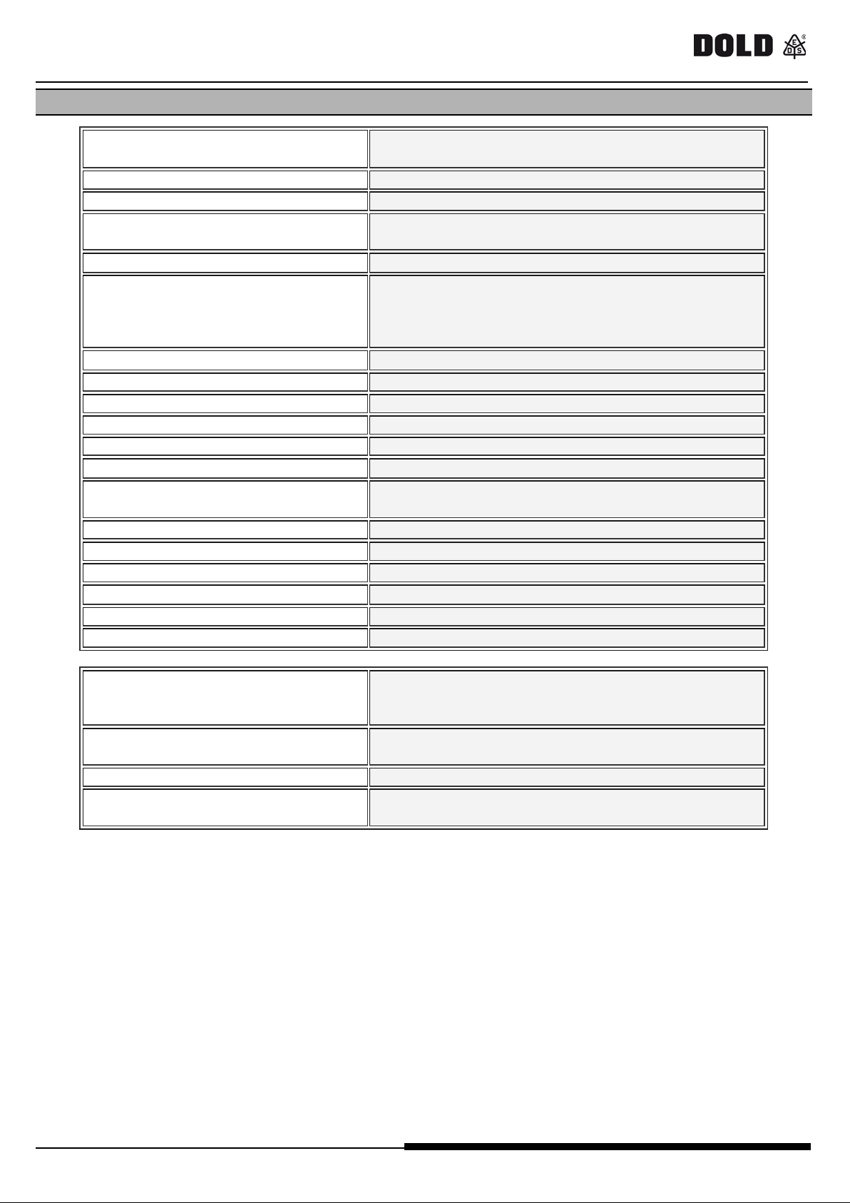
TECHNICAL FEATURES
Rated voltage
Connection to PC
Plug in with screw terminals
m ax. cross section for
connection:
stranded ferruled (isolated) or
2 x 0,25 ... 1,0 mm2 solid or
Enclosure
UL-Data
Listing is accomplished according to requirements of
UL hint
W ire connection
0265998 09.05.2017 LA 822P 15/17
Page 18
U G6951 / U G6952 / U G6954 / UG 6955 / UG6956 / U G6957
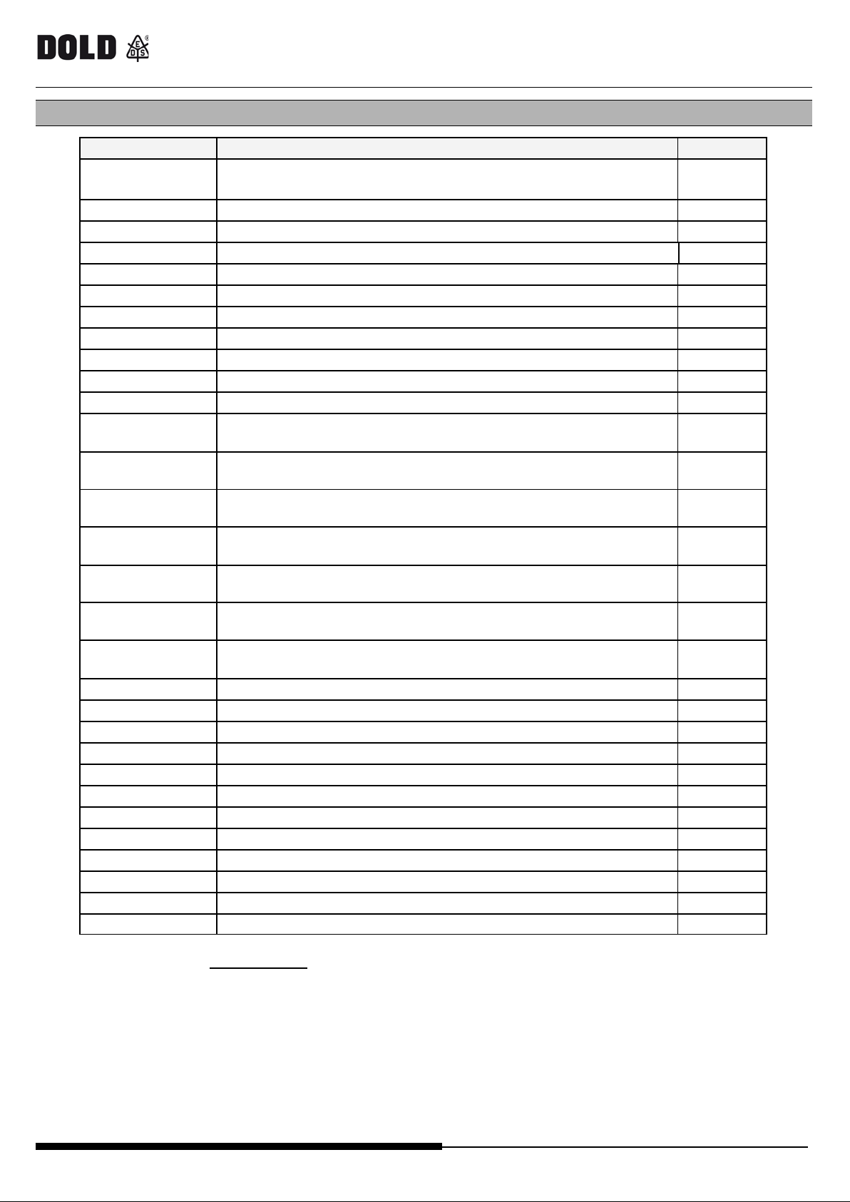
MODEL
DESCRIPTION
Reference
Control unit (8 Input / 2 dual channel OS S D),
UG6916.10
Input/Output module (8 Input / 2 dual channel OSSD)
0063819
UG6913.08
Input m odul e (8 input s)
0063820
UG6913.12
Input modul e (12 input s)
0064865
UG6913.16
Input modul e (16 input s)
0063821
UG6912.02
Output module OS SD (2 dual channel OS SD)
0063822
UG6912.04
Output module OS SD (4 dual channel OS SD)
0063823
UG6912.14
Output module rel ay (1 safety relay output)
0063824
UG6912.28
Output module rel ay (2 safety relay output)
0063825
UG6914.04/000
Output module rel ay (4 safety relay output)
0066057
UG6914.04/008
Output module rel ay (4 safety relay output + 8 s tatus out puts )
0065990
speed monitoring module
speed monitoring module
speed monitoring module
speed monitoring module
speed monitoring module
speed monitoring module
speed monitoring module
UG6918
Bus E x tender
0064866
UG6951
Fiel dbus modul e CanOpen
0063828
UG6952
Fiel dbus modul e P ROFIBUS DP
0063826
UG6954
Fiel dbus modul e P ROFINET
0064861
UG6955
Fiel dbus modul e E thernet IP
0064862
UG6956
Fiel dbus modul e E therCAT
0064863
UG6957
Fiel dbus modul e Universal Serial Bus (USB )
0064864
OA6911
memory chi p
0063829
OA6920
USB-Connect ion cable for PC
0064160
BU6921
Mounting set IN-RAIL-Bus 250mm for DIN 7, 5mm Rail
0064244
BU6922
Mounting set IN-RAIL-Bus 250mm for DIN 15m m Rail
0064245
PN6919
Software SAFEMASTER PRO Designer
0064246
SAFE MAST ER PRO fieldbus mo d ules
ORDERING DATA
UG6911.10
UG6917/002
UG6917/102
UG6917/112
UG6917/202
UG6917/222
with software SAFEMASTER PRO DESIGNER
(for 2 proximity switches)
(for 2 proximity switches + 1 TTL encoder)
(for 2 proximity switches + 2 TTL encoder)
(for 2 proximity switches + 1 HTL encoder)
(for 2 proximity switches + 2 HTL encoder)
0063818
0066059
0066060
0066061
0066062
0066063
UG6917/302
UG6917/332
(for 2 proximity switches + 1 Si n/Cos E ncoder)
(for 2 proximity switches + 2 Si n/Cos E ncoder)
0066064
0065992
Please, visit the website www.dold.com for the list of the authorized representative of each Country.
16/17 0265998 09.05.2017 LA822P
Page 19
UG6951 / UG6952 / UG6954 / UG6955 / UG6956 / UG6957
SAFE MAST ER PRO fieldbus mo d ules
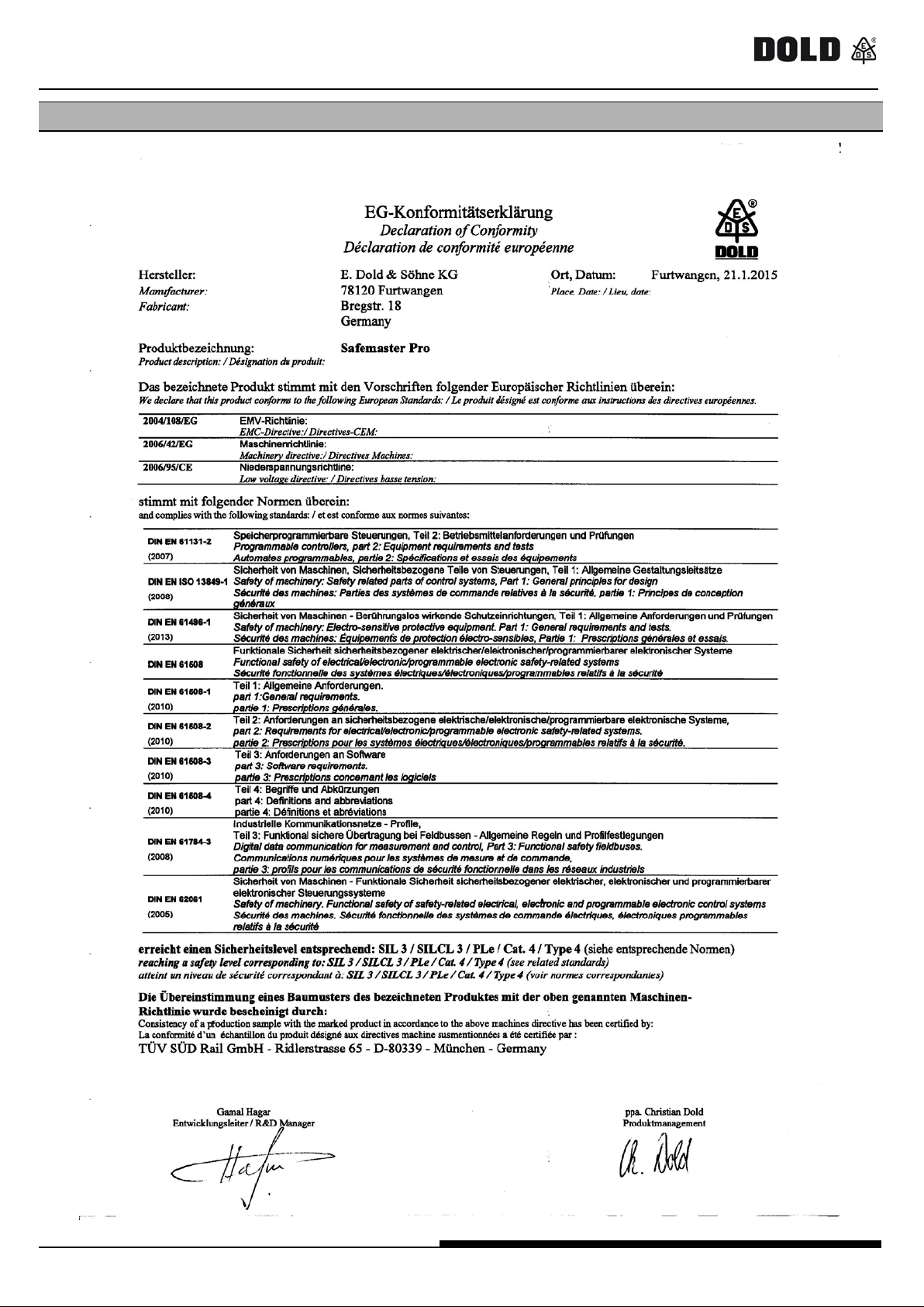
Declara tion of conformity
0265998 09.05.2017 LA822P 17/17
Page 20

Page 21

Page 22

Page 23

Page 24

UG6956 (EtherCAT)
LED 1: S TS
L ED 2: ERR
STATE
INDICATES
DESCRIPTION
STATE
INDICATES
DESCRIPTION
OFF
INIT
INIT or no pow er
OFF
No e rro r
No er ror or no power
OPERATIONAL state
Configuration not
valid
Status cha nge reque s ted by
master not possible
PRE-
OPERATIONAL
PRE-OPERA TIONA L
state
re d fl ashi ng
(2 fl ashes )
Watchdog
timeout
Synch m anager wat chdog
timeout
green flashing
(1 fl ash)
SAFE-
OPERATIONAL
SAFEOPERA TIONAL
state
module in EXCEPT ION state
Red
(Fatal Event)
System locked
-
-
-
UG6957 (USB)
2 LEDs: conn ect
STATE
INDICATES
DESCRIPTION
ON
USB connection
Module connected on PC
OFF
no USB connection
Module not connected
User manual 0265998 09.05.2017 LA822P
green OPERATIONA L
green flashing
red flas hing
red Controller fault
Table (automatische Zählung rein kopieren)
Table (automatische Zählung rein kopieren)
 Loading...